

Sit TRASCO GRMP Series, TRASCO GRMALU Series, TRASCO GRB Series, TRASCO GRS Series, TRASCO GRF Series Operating And Maintenance Manual

TRASCO® Couplings
OPERATING AND MAINTENANCE MANUAL
SIT S.p.A. Viale A. Volta, 2 - 20090 Cusago (MI) - Italy
Tel. +39.02891441 Fax +39.0289144291 - info@sitspa.com www.sitspa.com

INDEX
Pag.
1
1.1
1.2
1.3
1.4
1.5
2
2.1
2.1.1
2.1.2
2.1.3
2.1.4
2.1.5
2.1.6
2.1.7
2.2
2.2.1
2.3
3
4
4.1
4.2
4.2.1
4.2.2
4.3
44
4.4.1
4.4.2
4.4.3
5
5.1
5.2
5.3
5.3.1
5.3.2
5.4
5.4.1
5.4.2
5.5
5.6
5.7
5.8
5.8.1
5.8.2
5.9
GENERAL INFORMATION 4
PURPOSE OF THE DOCUMENT 4
PROPER USE 4
WARNING SYMBOLS FOR SAFETY 4
GENERAL ADVICE IN CASE OF DANGER 5
REFERENCE LAWS AND STANDARDS 5
CHARACTERISTICS OF TRASCO® COUPLINGS 5
HUBS 6
GRMP SERIES HUBS 6
GRMALU SERIES HUBS 8
GRB SERIES HUBS 8
GRS SERIES HUBS 10
GRF SERIES HUBS 11
HUBS MACHINING 13
POSITION AND SIZE OF THE SETSCREW 14
ELASTIC SPIDER 15
ELASTIC SPIDER PERFORMANCE 16
COUPLING MISALIGNMENTS 17
STORAGE 17
ASSEMBLING 18
GRMP COUPLING ASSEMBLY 18
GRB COUPLING ASSEMBLING 20
TAPER BUSH MOUNTING 20
TAPER BUSH DISASSEMBLING 21
GRS COUPLING ASSEMBLING 21
GRF COUPLING ASSEMBLING 22
FLANGE-FLANGE VERSION 22
SHAFT-FLANGE VERSION 23
SHAFT-SHAFT VERSION 24
ATEX ANNEX 25
ATEX ZONE CLASSIFICATION 25
ATEX EQUIPMENT CLASSIFICATION 26
APPROPRIATE USE OF TRASCO® COUPLINGS IN ATEX ZONES 26
GAS TEMPERATURE CLASSES FOR GROUP II EQUIPMENT 26
TEMPERATURE CLASSES FOR GROUP I EQUIPMENT 26
MARKING 27
COMPLETE MARKING 27
COMPACT MARKING 27
HUB MACHINING IN ATEX ENVIRONMENT 28
ELASTIC SPIDER CHECK 28
INTERNAL MANUFACTURING CHECK 29
STARTING 29
PROTECTION DEVICES FOR COUPLINGS IN HAZARDOUS ATMOSPHERES 30
ELECTRICAL CONTINUITY 30
DECLARATION OF CONFORMITY 31

INDEX OF TABLES
Pag.
TABLE 2.1
TABLE 2.2
TABLE 2.3
TABLE 2.4
TABLE 2.5
TABLE 2.6
TABLE 2.7
TABLE 2.8
TABLE 2.9
TABLE 2.10
TABLE 2.11
TABLE 4.1
TABLE 4.2
TABLE 4.3
TABLE 5.1
TABLE 5.2
TABLE 5.3
TABLE 5.4
TRASCO®: HUBS MATERIALS 6
DIMENSIONS TRASCO® GRMP 7
TRASCO® GRMP LENGTHS 7
DIMENSIONS TRASCO® GRMALU 8
DIMENSIONS TRASCO® GRB 9
DIMENSIONS TRASCO® GRS 10
DIMENSIONS TRASCO® GRF 11
DIMENSIONS TRASCO® GRF 12
TRASCO®: POSIZIONE GRANO DI FISSAGGIO 14
ELASTIC SPIDER PERFORMANCE 16
TRASCO®: MISALIGNMENTS 17
QUOTE M 19
GRANI BUSSOLE CONICHE 20
GRF SCREWS 22
ATEX ZONE CLASSIFICATION 25
ATEX GROUPS AND CATEGORIES CLASSIFICATION 26
GAS TEMPERATURE CLASSES 26
QUOTE Z FOR CHECKING SPIDER WEAR 28
INDEX OF FIGURES
Pag.
FIGURE 2-1
FIGURE 2-2
FIGURE 2-3
FIGURE 2-4
FIGURE 2-5
FIGURE 2-6
FIGURE 2-7
FIGURE 2-8
FIGURE 2-9
FIGURE 4-1
FIGURE 4-2
FIGURE 4-3
FIGURE 4-4
FIGURE 4-5
FIGURE 4-6
FIGURE 4-7
TRASCO® GRMP HUBS 6
TRASCO® SERIES GRB 8
TRASCO® SERIES GRS 10
TRASCO® GRF HUBS 11
TRASCO® GRF C HUBS 12
PROCESSING TOLERANCE 13
SETSCREW POSITION 14
ELASTIC SPIDER 15
TRASCO®: MISALIGNMENTS 17
GRMP COUPLING 18
GRMP: MOUNTING 19
TYPES OF GRB 20
GRS INTERMEDIATE ELEMENT 21
FLANGE-FLANGE VERSION (CF/CFN) 22
SHAFT-FLANGE VERSION (CF/CFN) 23
SHAFT-SHAFT VERSION (CF/CFN) 24
www.sitspa.com TRASCO® - Operating and Maintenance Manual
1 General information
We recommend that you carefully read all the mounting instructions before installing the coupling, paying particular attention to the safety
instructions.
TRASCO® coupling is suitable for use in potentially explosive atmospheres. When using the coupling in hazardous areas, strictly observe
the special information and instructions regarding safety in the ATEX attachment.
The mounting instructions are part of the product; please keep them safe and close to the coupling.
They are available in electronic format on the website www.sitspa.com.
All the rights of this manual are reserved and are the property of SIT S.p.A.; therefore, its sale and reproduction without permission are
prohibited.
1.1 Purpose of the document
The purpose of this document is the description of the TRASCO
use in potentially explosive environments in accordance with ATEX Directive 2014/34/EU.
All the indications are provided, so that it is properly dimensioned, stored and assembled.
As regards the couplings that have to work in potentially explosive environments, all the indications and standards for identifying the
installation areas for which the coupling is certified to operate in safe conditions are provided.
®
couplings, both in the standard version and in the version suitable for
1.2 Proper use
Before handling a SIT coupling for moving, installing, or performing maintenance, it is advisable to carefully read the mounting instructions.
Any kind of changes aren’t authorized except those expressly provided for in the operating and maintenance manual.
SIT assumes no liability for damage resulting from tampered material and, therefore, no longer original.
SIT reserves the right to make changes to the product; as a consequence, this manual will be updated. The technical specifications listed
in the operating and maintenance manual exactly match the state of the art at the time of printing.
1.3 Warning symbols for safety
The warning symbols included in this manual alert the user to possible risks that may occur during handling, assembling and use of the
coupling.
It is necessary to pay particular attention to them.
STOP
114.01 - Rev. 3 - 24 April 2019 Approved by SIT S.p.A.
DANGER
CAUTION
ATTENTION
PRECAUTION
Danger of injury to persons.
Possible damages to the machine.
Important guidelines to follow.
Hints about explosion protections.
4
www.sitspa.com TRASCO® - Operating and Maintenance Manual
1.4 General advice in case of danger
DANGER!
Every operation performed on the coupling, either with mounting
or maintenance, must be carried out with the machine not con-
STOP
nected to the power supply. Accidental contact with the rotating
parts can cause serious injury to the operator. It is recommended
to read these operating instructions to ensure safety.
• Affix proper warning signs around the machine
• Instruct the operator before giving permission to work on the coupling
• Operate on the coupling and on the transmission in safe conditions
• Make sure the machine power is disconnected before carrying out any operation
• Do not touch any moving part of the machine and wait until it stops completely
• Protect the coupling against accidental contact with protection devices
1.5 Reference laws and standards
This evaluation was carried out in accordance with the provisions of the relevant laws, directives, standards mentioned below:
DIN 740/2
ATEX DIRECTIVE 2014/34/EU
ATEX GUIDELINES 2014/34/EU
EN 1127-1:2011
EN 13463-1:2009
EN 13463-5:2011
Reference standard for flexible couplings
Equipment and protective systems intended for use in potentially explosive atmospheres
Guidelines to the application of Directive 2014/34/EU
Explosion prevention and protection against explosion. Basic concepts and methodology
Non-electrical equipment for potentially explosive atmospheres. Basic method and requirements
Non-electrical equipment for potentially explosive atmospheres. Constructional safety "c"
®
2 Characteristics of TRASCO
®
TRASCO
is very compact and allows a safe transmission of motion between the motor and the driven machine, absorbing shocks and torsional
vibrations. It also allows, through the elastic deformation of the elastic spider, to compensate for angular, radial and axial misalignments
due to small variations in length of the shafts. The hub teeth and spider profiles are designed so as to obtain a uniform pressure distribution.
The elastic element is subject only to compression stress and does not induce any axial or radial stresses, providing the TRASCO®
coupling with great load capacity and durability. The coupling can be assembled both horizontally and vertically, and it correctly tolerates
load variations and reversals.
couplings are a flexible and constant-velocity coupling that ensures maximum performance with same overall dimensions. It
couplings
The TRASCO® series is suitable for use in areas classified with the
presence of flammable gases, vapours and mists or combustible
dusts (Zone 1/21, category 2 GD).
It is designed and built in accordance with the ATEX Directive
2014/34/EU and in accordance with the following European stan
dards:
• EN 1127-1:2011
• EN 13463-1:2009
-
• EN 13463-5:2011
114.01 - Rev. 3 - 24 April 2019 Approved by SIT S.p.A.
5
www.sitspa.com TRASCO® - Operating and Maintenance Manual
GRMP...A
AR
GRMP...B
2.1 Hubs
The TRASCO® coupling consists of two metal hubs that have cut-outs with circular sections which contain the teeth of the elastic spider.
The materials of standard hubs are laminated cast iron, spheroidal cast iron or aluminium, depending on the types and sizes.
For details see TABLE 2.1 - TRASCO®: hubs materials.
TABLE 2.1 - TRASCO®: hubs materials
SERIES SIZE STANDARD MATERIAL OPTIONAL MATERIALS
19/24 Steel sintered Steel / Stainless steel / Aluminium / spheroidal cast iron
GRMP
from 24/32 to 90/100 Grey cast iron Steel / Stainless steel / Aluminium / spheroidal cast iron
from 100/110 to 180/200 spheroidal cast iron Steel / Stainless steel / Aluminium / spheroidal cast iron
GRMALU
GRB
GRS
GRF
Table 2.1 - Note: For details contact the Technical Department.
All Aluminium diecast Steel / Stainless steel / Aluminium / spheroidal cast iron
All Grey cast iron Steel / Stainless steel / Aluminium / spheroidal cast iron
All Aluminium Steel / Stainless steel / Aluminium / spheroidal cast iron
All spheroidal cast iron Steel / Stainless steel / Aluminium / spheroidal cast iron
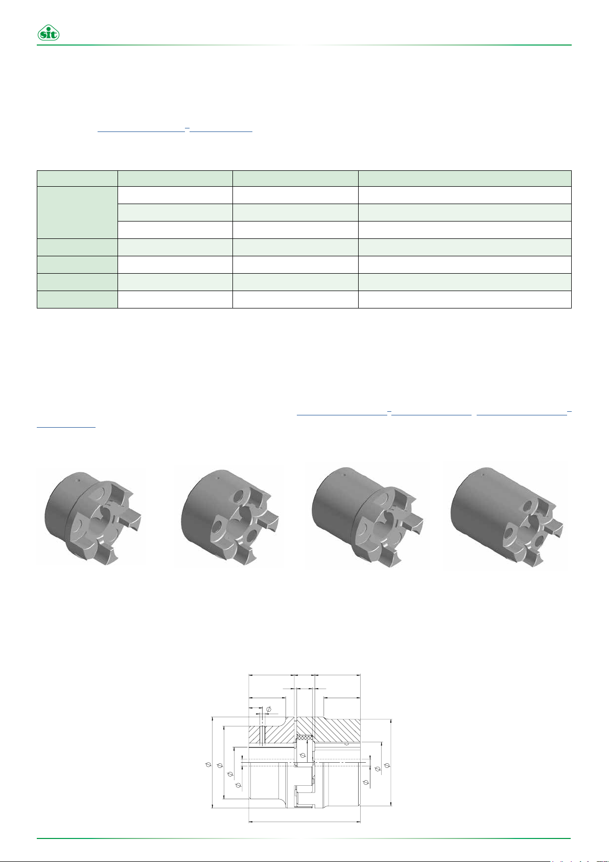
2.1.1 GRMP series hubs
The TRASCO® hubs series GRMP are made, depending on the size, in two versions: A (hollow) and B (full).
They are different for the exterior design and for the maximum bore that can be achieved.
Each of them has the respective AL and BL extended version (TABLE 2.2 - TRASCO® GRMP dimensions, TABLE 2.3 - TRASCO®
GRMP lengths).
Table 2.3 - TRASCO® GRMP lengths
A B AL BL
Figure 2-1 - GRMP TRASCO® Hubs
The milling of the seat of the flexible element of the GRMP guarantees a perfect coupling with the elastic spider in order to ensure a long
life in the correct operating conditions.
H
I
t
E
A
aF
gF
Hub Hub
Mozzo
“A”
114.01 - Rev. 3 - 24 April 2019 Approved by SIT S.p.A.
M
N
P
G
L
H
SS
I
B
bF
Mozzo
gF
“B”
6

www.sitspa.com TRASCO® - Operating and Maintenance Manual
Table 2.2 - Dimension TRASCO® GRMP
SIZE Fa
19/24
24/32
28/38
38/45
42/55
48/60
55/70
65/75
75/90
90/100
100/110
110/125
125/145
140/160
160/185
180/200
- 24 - - - - 40 40 16 2 12 18
24 32 8 10 8 10 55 40 55 18 2 14 27
28 38 8 10 8 10 65 48 65 20 2,5 15 30
38 45 10 12 14 14 80 66 80 24 3 18 38
42 55 10 12 16 16 95 75 95 26 3 20 46
48 60 12 12 16 16 105 85 105 28 3,5 21 51
55 70 15 15 16 16 120 98 120 30 4 22 60
65 75 15 15 20 20 135 115 135 35 4,5 26 68
75 90 15 15 22 22 160 135 160 40 5 30 80
90 100 20 20 30 30 200 160 180 45 5,5 34 100
115 - 45 - - - 225 180 - 50 6 38 113
125 - 55 - - - 255 200 - 55 6,5 42 127
145 - 55 - - - 290 230 - 60 7 46 147
160 - 55 - - - 320 255 - 65 8 50 165
185 - 75 - - - 370 290 - 75 9 57 190
200 - 80 - - - 420 325 - 85 11 64 220
Fb
max
Table 2.2 - * dimensions in mm
®
Table 2.3 - TRASCO
GRMP lengths
Fg
max Fb AL BL
E A B M S N G
SIZE
19/24
24/32
28/38
38/45
42/55
48/60
55/70
65/75
75/90
90/100
100/110
110/125
125/145
140/160
160/185
180/200
Execution A Execution B Execution AL Execution BL
H L (A+A) I H L (B+B) I H L (AL+AL) I H L (BL+BL) I
25 66 - - - - - 50 - - 25 66
30 78 24 - 50 128 44 60 128 - 30 78
35 90 28 - 60 160 53 80 160 - 35 90
45 114 37 - 80 214 72 110 214 - 45 114
50 126 40 - 110 246 100 110 246 - 50 126
56 140 45 - 110 278 99 140 278 - 56 140
65 160 52 - 110 280 97 140 280 - 65 160
75 185 61 - 140 315 126 140 315 - 75 185
85 210 69 - 140 350 124 170 350 - 85 210
100 245 81 81 170 425 151 210 425 191 100 245
110 270 89 - - - - - - - 110 270
120 295 96 - - - - - - - 120 295
140 340 112 - - - - - - - 140 340
155 375 124 - - - - - - - 155 375
175 425 140 - - - - - - - 175 425
195 475 156 - - - - - - - 195 475
Table 2.3 - * dimensions in mm
114.01 - Rev. 3 - 24 April 2019 Approved by SIT S.p.A.
7
www.sitspa.com TRASCO® - Operating and Maintenance Manual
Ø
d
Ø
d
L
Ø
B
Ø
B
Ø
E
I I
NS
H H
S
M
GRMP...A
AR
GRMP...B
2.1.2 GRMALU series hubs
The TRASCO® GRMALU series hubs are made of die-casting aluminium for A and B versions
(TABLE 2.4 - TRASCO® GRMALU dimensions).
E
Table 2.4 - Dimensions TRASCO® GRMALU
SIZE
19/24
24/32
28/38
38/45
42/55
48/60
Fa
maxFbmax
- 24 - - 40 40 40 66 25 16 2 12 - 18 10 M5
24 32 - - 55 40 55 78 30 18 2 14 24 27 10 M5
28 38 12 28 65 48 65 90 35 20 2.5 15 28 30 15 M6
38 45 22 38 80 66 77 114 45 24 3 18 37 38 15 M8
- 55 - 22 95 - 95 126 50 26 3 20 - 46 20 M8
- 60 - 30 105 - 105 140 56 28 3.5 21 - 51 20 M8
Table 2.4 - * dimensions in mm
Fg
A B
H
I
t
P
A
aF
gF
Hub Hub
Mozzo
“A”
E A B L H M S N I G t P
M
N
G
H
SS
I
B
bF
gF
Mozzo
“B”
L
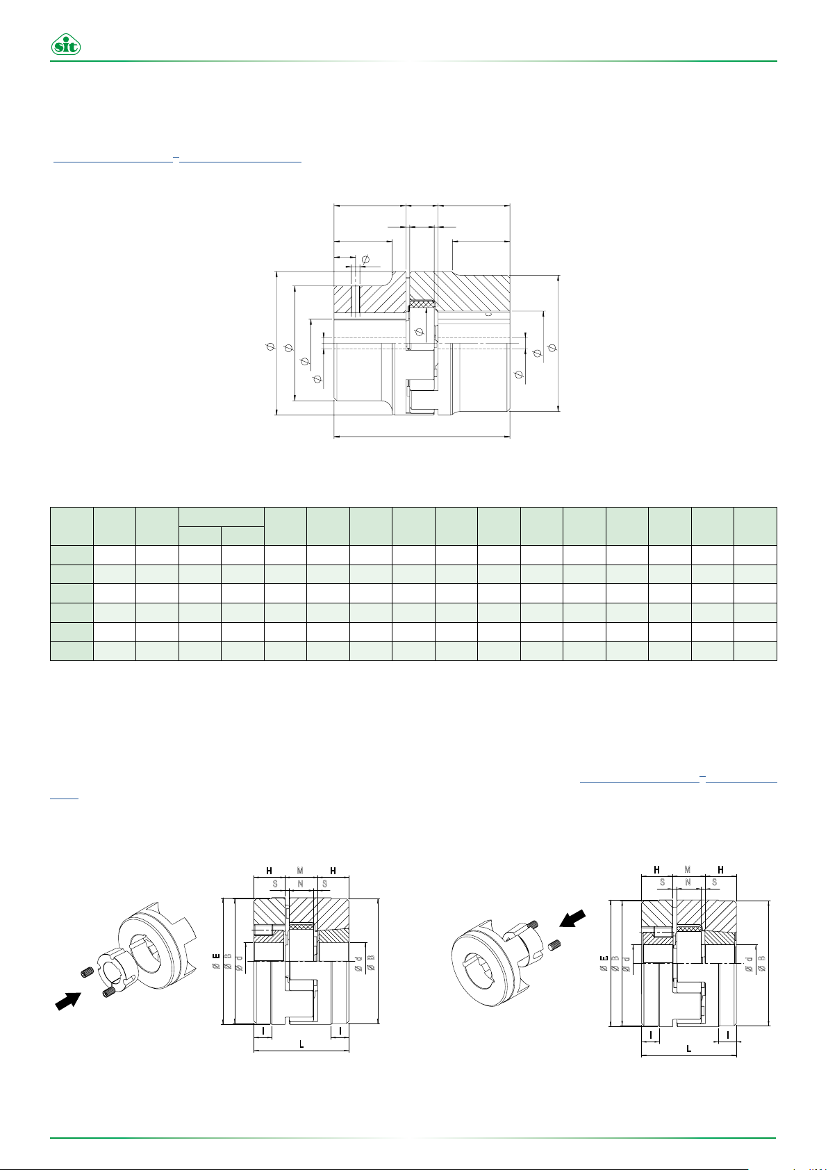
2.1.3 GRB series hubs
The TRASCO® GRB series couplings for taper bush combines high performance characteristics, typical of standard hub coupling, the
ease of use, assembly and disassembly, resulting from the coupling with a SER-SIT® taper bush. (TABLE 2.5 - TRASCO® GRB dimen-
sions).
They are produced in two versions:
• B1, with bush mounting from the outside of the hub
• B2, with bush mounting from the inside of the hub
B1 B2
H H
H HM
NS S
E
B
d
Ø
Ø
Ø
I I
L
B
d
Ø
Ø
E
B
d
Ø
Ø
Ø
M
NS
I I
L
Figure 2-2 - TRASCO® series GRB
S
B
d
Ø
Ø
114.01 - Rev. 3 - 24 April 2019 Approved by SIT S.p.A.
8

www.sitspa.com TRASCO® - Operating and Maintenance Manual
Table 2.5 - DimensionsTRASCO® GRB
SIZE
28/38 1108 (2820) 65 65 66 23 20 2,5 15 -
38/45 1108 (2820) 80 78 70 23 24 3 18 15
42/55 1610 (4025) 95 94 78 26 26 3 20 16
48/60 1615 (4040) 105 104 106 39 28 3,5 21 28
55/70 2012 (5030) 120 118 96 33 30 4 22 20
65/75 2012 (5030) 135 133 101 33 35 4,5 26 19
75/90 2517 (6545) 160 158 130 45 40 5 30 36
90/100 3535 (9090) 200 180 223 89 45 5,5 34 70
SER-SIT SIZE
1108 (2820)
1610 (4025)
1615 (4040)
2012 (5030)
2517 (6545)
3535 (9090)
SER-SIT TAPER
BUSH
[mm] 11-12-14-15-16-17-18-19-20-22-24-25-26-27-28
[inch] 3/8-1/2-5/8-3/4-7/8-1-1 1/8
[mm] 12-14-15-16-18-19-20-22-24-25-26-28-30-32-35-38-40-42
[inch] 3/8-1/2-5/8-3/4-7/8-1-1 1/8-1 1/4-1 3/8-1 1/2-1 5/8
[mm] 12-14-15-16-18-19-20-22-24-25-26-28-30-32-35-38-40-42
[inch] 1/2-5/8-3/4-7/8-1-1 1/8-1 1/4-1 3/8-1 1/2-1 5/8-1 3/4
[mm] 14-15-16-18-19-20-22-24-25-26-28-30-32-35-38-40-42-45-48-50
[inch] 5/8-3/4-7/8-1-1 1/8-1 1/4-1 3/8-1 1/2-1 5/8-1 3/4-1 7/8-2
[mm] 18-19-20-22-24-25-28-30-32-35-38-40-42-45-48-50-55-60-65
[inch] 3/4-7/8-1-1 1/8-1 1/4-1 3/8-1 1/2-1 5/8-1 3/4-1 7/8-2-2 1/8-2 1/4-2 3/8-2 1/2
[mm] 25-35-38-40-42-45-48-50-55-60-65-70-75-80-85-90
[inch] 1 1/2-1 5/8-1 3/4-1 7/8-2-2 1/8-2 1/4-2 3/8-2 1/2-2 5/8-2 3/4-2 7/8-3-3 1/8-3 1/4-3 3/8-3 1/2
E B L H M S N I
BORE DIAMETER (H7)
Tolerance of the seat of the keyway JS9
Torque
[Nm]
1300
5000
150
490
490
800
Table 2.5
* dimensions in mm
** Transmittable friction torque without the keyway
114.01 - Rev. 3 - 24 April 2019 Approved by SIT S.p.A.
9
www.sitspa.com TRASCO® - Operating and Maintenance Manual
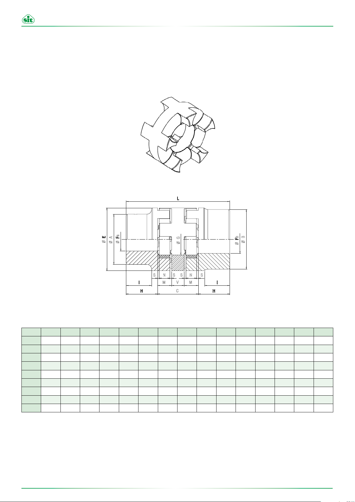
2.1.4 GRS series hubs
The GRS series hubs are intermediate elements that increase the ability of the coupling to compensate for axial, radial and angular
misalignments.
The presence of two elastic spiders allows a high damping effect of the vibrations, with consequent reduction of the transmission noise
and a reduced wear of the connected components, such as bearings.
Figure 2-3 - TRASCO® GRS series
L
E
Fa
A
Ø
Ø
Ø
S N N S
I I
H C H
Table 2.6 - DimensionsTRASCO
SIZE Fa Fb H V C M S N L E A B G ΔKr ΔKw
24/32
28/38
38/45
42/55
48/60
55/70
65/75
75/90
90/100
9-24 11-32 30 16 52 18 2 14 112 55 40 55 27 0,89 1°30’
9-28 11-38 35 18 58 20 2,5 15 128 65 48 65 30 1 1°30’
11-38 13-45 45 20 68 24 3 18 158 80 66 80 38 1,15 1°30’
11-42 13-55 50 22 74 26 3 20 174 95 75 95 46 1,26 1°30’
13-48 13-60 56 24 80 28 3,5 21 192 105 85 105 51 1,36 1°30’
16-55 16-70 65 28 88 30 4 22 218 120 98 120 60 1,52 1°30’
16-65 16-75 75 32 102 35 4,5 26 252 135 115 135 68 1,75 1°30’
16-75 16-90 85 36 116 40 5 30 286 160 135 160 80 2 1°30’
21-90 21-100 100 40 130 45 5,5 34 330 200 160 180 100 2,5 1°30’
®
GRS
G
Ø
S S
M V M
Fb
Ø
B
Ø
* dimensions in mm
114.01 - Rev. 3 - 24 April 2019 Approved by SIT S.p.A.
10
 Loading...