

Sit TRASCO GRMP Series, TRASCO GRMALU Series, TRASCO GRB Series, TRASCO GRS Series, TRASCO GRF Series Operating And Maintenance Manual

TRASCO® Couplings
OPERATING AND MAINTENANCE MANUAL
SIT S.p.A. Viale A. Volta, 2 - 20090 Cusago (MI) - Italy
Tel. +39.02891441 Fax +39.0289144291 - info@sitspa.com www.sitspa.com

INDEX
Pag.
1
1.1
1.2
1.3
1.4
1.5
2
2.1
2.1.1
2.1.2
2.1.3
2.1.4
2.1.5
2.1.6
2.1.7
2.2
2.2.1
2.3
3
4
4.1
4.2
4.2.1
4.2.2
4.3
44
4.4.1
4.4.2
4.4.3
5
5.1
5.2
5.3
5.3.1
5.3.2
5.4
5.4.1
5.4.2
5.5
5.6
5.7
5.8
5.8.1
5.8.2
5.9
GENERAL INFORMATION 4
PURPOSE OF THE DOCUMENT 4
PROPER USE 4
WARNING SYMBOLS FOR SAFETY 4
GENERAL ADVICE IN CASE OF DANGER 5
REFERENCE LAWS AND STANDARDS 5
CHARACTERISTICS OF TRASCO® COUPLINGS 5
HUBS 6
GRMP SERIES HUBS 6
GRMALU SERIES HUBS 8
GRB SERIES HUBS 8
GRS SERIES HUBS 10
GRF SERIES HUBS 11
HUBS MACHINING 13
POSITION AND SIZE OF THE SETSCREW 14
ELASTIC SPIDER 15
ELASTIC SPIDER PERFORMANCE 16
COUPLING MISALIGNMENTS 17
STORAGE 17
ASSEMBLING 18
GRMP COUPLING ASSEMBLY 18
GRB COUPLING ASSEMBLING 20
TAPER BUSH MOUNTING 20
TAPER BUSH DISASSEMBLING 21
GRS COUPLING ASSEMBLING 21
GRF COUPLING ASSEMBLING 22
FLANGE-FLANGE VERSION 22
SHAFT-FLANGE VERSION 23
SHAFT-SHAFT VERSION 24
ATEX ANNEX 25
ATEX ZONE CLASSIFICATION 25
ATEX EQUIPMENT CLASSIFICATION 26
APPROPRIATE USE OF TRASCO® COUPLINGS IN ATEX ZONES 26
GAS TEMPERATURE CLASSES FOR GROUP II EQUIPMENT 26
TEMPERATURE CLASSES FOR GROUP I EQUIPMENT 26
MARKING 27
COMPLETE MARKING 27
COMPACT MARKING 27
HUB MACHINING IN ATEX ENVIRONMENT 28
ELASTIC SPIDER CHECK 28
INTERNAL MANUFACTURING CHECK 29
STARTING 29
PROTECTION DEVICES FOR COUPLINGS IN HAZARDOUS ATMOSPHERES 30
ELECTRICAL CONTINUITY 30
DECLARATION OF CONFORMITY 31

INDEX OF TABLES
Pag.
TABLE 2.1
TABLE 2.2
TABLE 2.3
TABLE 2.4
TABLE 2.5
TABLE 2.6
TABLE 2.7
TABLE 2.8
TABLE 2.9
TABLE 2.10
TABLE 2.11
TABLE 4.1
TABLE 4.2
TABLE 4.3
TABLE 5.1
TABLE 5.2
TABLE 5.3
TABLE 5.4
TRASCO®: HUBS MATERIALS 6
DIMENSIONS TRASCO® GRMP 7
TRASCO® GRMP LENGTHS 7
DIMENSIONS TRASCO® GRMALU 8
DIMENSIONS TRASCO® GRB 9
DIMENSIONS TRASCO® GRS 10
DIMENSIONS TRASCO® GRF 11
DIMENSIONS TRASCO® GRF 12
TRASCO®: POSIZIONE GRANO DI FISSAGGIO 14
ELASTIC SPIDER PERFORMANCE 16
TRASCO®: MISALIGNMENTS 17
QUOTE M 19
GRANI BUSSOLE CONICHE 20
GRF SCREWS 22
ATEX ZONE CLASSIFICATION 25
ATEX GROUPS AND CATEGORIES CLASSIFICATION 26
GAS TEMPERATURE CLASSES 26
QUOTE Z FOR CHECKING SPIDER WEAR 28
INDEX OF FIGURES
Pag.
FIGURE 2-1
FIGURE 2-2
FIGURE 2-3
FIGURE 2-4
FIGURE 2-5
FIGURE 2-6
FIGURE 2-7
FIGURE 2-8
FIGURE 2-9
FIGURE 4-1
FIGURE 4-2
FIGURE 4-3
FIGURE 4-4
FIGURE 4-5
FIGURE 4-6
FIGURE 4-7
TRASCO® GRMP HUBS 6
TRASCO® SERIES GRB 8
TRASCO® SERIES GRS 10
TRASCO® GRF HUBS 11
TRASCO® GRF C HUBS 12
PROCESSING TOLERANCE 13
SETSCREW POSITION 14
ELASTIC SPIDER 15
TRASCO®: MISALIGNMENTS 17
GRMP COUPLING 18
GRMP: MOUNTING 19
TYPES OF GRB 20
GRS INTERMEDIATE ELEMENT 21
FLANGE-FLANGE VERSION (CF/CFN) 22
SHAFT-FLANGE VERSION (CF/CFN) 23
SHAFT-SHAFT VERSION (CF/CFN) 24
www.sitspa.com TRASCO® - Operating and Maintenance Manual
1 General information
We recommend that you carefully read all the mounting instructions before installing the coupling, paying particular attention to the safety
instructions.
TRASCO® coupling is suitable for use in potentially explosive atmospheres. When using the coupling in hazardous areas, strictly observe
the special information and instructions regarding safety in the ATEX attachment.
The mounting instructions are part of the product; please keep them safe and close to the coupling.
They are available in electronic format on the website www.sitspa.com.
All the rights of this manual are reserved and are the property of SIT S.p.A.; therefore, its sale and reproduction without permission are
prohibited.
1.1 Purpose of the document
The purpose of this document is the description of the TRASCO
use in potentially explosive environments in accordance with ATEX Directive 2014/34/EU.
All the indications are provided, so that it is properly dimensioned, stored and assembled.
As regards the couplings that have to work in potentially explosive environments, all the indications and standards for identifying the
installation areas for which the coupling is certified to operate in safe conditions are provided.
®
couplings, both in the standard version and in the version suitable for
1.2 Proper use
Before handling a SIT coupling for moving, installing, or performing maintenance, it is advisable to carefully read the mounting instructions.
Any kind of changes aren’t authorized except those expressly provided for in the operating and maintenance manual.
SIT assumes no liability for damage resulting from tampered material and, therefore, no longer original.
SIT reserves the right to make changes to the product; as a consequence, this manual will be updated. The technical specifications listed
in the operating and maintenance manual exactly match the state of the art at the time of printing.
1.3 Warning symbols for safety
The warning symbols included in this manual alert the user to possible risks that may occur during handling, assembling and use of the
coupling.
It is necessary to pay particular attention to them.
STOP
114.01 - Rev. 3 - 24 April 2019 Approved by SIT S.p.A.
DANGER
CAUTION
ATTENTION
PRECAUTION
Danger of injury to persons.
Possible damages to the machine.
Important guidelines to follow.
Hints about explosion protections.
4
www.sitspa.com TRASCO® - Operating and Maintenance Manual
1.4 General advice in case of danger
DANGER!
Every operation performed on the coupling, either with mounting
or maintenance, must be carried out with the machine not con-
STOP
nected to the power supply. Accidental contact with the rotating
parts can cause serious injury to the operator. It is recommended
to read these operating instructions to ensure safety.
• Affix proper warning signs around the machine
• Instruct the operator before giving permission to work on the coupling
• Operate on the coupling and on the transmission in safe conditions
• Make sure the machine power is disconnected before carrying out any operation
• Do not touch any moving part of the machine and wait until it stops completely
• Protect the coupling against accidental contact with protection devices
1.5 Reference laws and standards
This evaluation was carried out in accordance with the provisions of the relevant laws, directives, standards mentioned below:
DIN 740/2
ATEX DIRECTIVE 2014/34/EU
ATEX GUIDELINES 2014/34/EU
EN 1127-1:2011
EN 13463-1:2009
EN 13463-5:2011
Reference standard for flexible couplings
Equipment and protective systems intended for use in potentially explosive atmospheres
Guidelines to the application of Directive 2014/34/EU
Explosion prevention and protection against explosion. Basic concepts and methodology
Non-electrical equipment for potentially explosive atmospheres. Basic method and requirements
Non-electrical equipment for potentially explosive atmospheres. Constructional safety "c"
®
2 Characteristics of TRASCO
®
TRASCO
is very compact and allows a safe transmission of motion between the motor and the driven machine, absorbing shocks and torsional
vibrations. It also allows, through the elastic deformation of the elastic spider, to compensate for angular, radial and axial misalignments
due to small variations in length of the shafts. The hub teeth and spider profiles are designed so as to obtain a uniform pressure distribution.
The elastic element is subject only to compression stress and does not induce any axial or radial stresses, providing the TRASCO®
coupling with great load capacity and durability. The coupling can be assembled both horizontally and vertically, and it correctly tolerates
load variations and reversals.
couplings are a flexible and constant-velocity coupling that ensures maximum performance with same overall dimensions. It
couplings
The TRASCO® series is suitable for use in areas classified with the
presence of flammable gases, vapours and mists or combustible
dusts (Zone 1/21, category 2 GD).
It is designed and built in accordance with the ATEX Directive
2014/34/EU and in accordance with the following European stan
dards:
• EN 1127-1:2011
• EN 13463-1:2009
-
• EN 13463-5:2011
114.01 - Rev. 3 - 24 April 2019 Approved by SIT S.p.A.
5
www.sitspa.com TRASCO® - Operating and Maintenance Manual
GRMP...A
AR
GRMP...B
2.1 Hubs
The TRASCO® coupling consists of two metal hubs that have cut-outs with circular sections which contain the teeth of the elastic spider.
The materials of standard hubs are laminated cast iron, spheroidal cast iron or aluminium, depending on the types and sizes.
For details see TABLE 2.1 - TRASCO®: hubs materials.
TABLE 2.1 - TRASCO®: hubs materials
SERIES SIZE STANDARD MATERIAL OPTIONAL MATERIALS
19/24 Steel sintered Steel / Stainless steel / Aluminium / spheroidal cast iron
GRMP
from 24/32 to 90/100 Grey cast iron Steel / Stainless steel / Aluminium / spheroidal cast iron
from 100/110 to 180/200 spheroidal cast iron Steel / Stainless steel / Aluminium / spheroidal cast iron
GRMALU
GRB
GRS
GRF
Table 2.1 - Note: For details contact the Technical Department.
All Aluminium diecast Steel / Stainless steel / Aluminium / spheroidal cast iron
All Grey cast iron Steel / Stainless steel / Aluminium / spheroidal cast iron
All Aluminium Steel / Stainless steel / Aluminium / spheroidal cast iron
All spheroidal cast iron Steel / Stainless steel / Aluminium / spheroidal cast iron
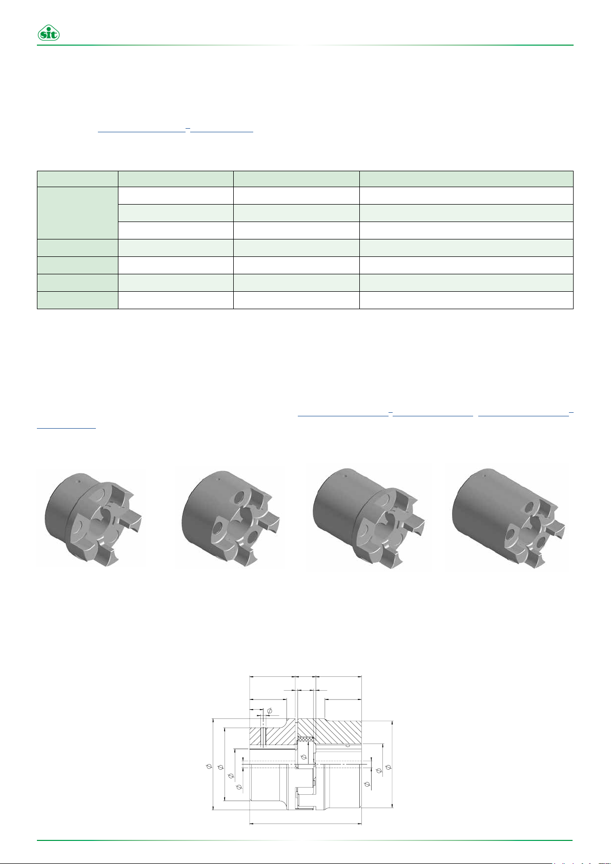
2.1.1 GRMP series hubs
The TRASCO® hubs series GRMP are made, depending on the size, in two versions: A (hollow) and B (full).
They are different for the exterior design and for the maximum bore that can be achieved.
Each of them has the respective AL and BL extended version (TABLE 2.2 - TRASCO® GRMP dimensions, TABLE 2.3 - TRASCO®
GRMP lengths).
Table 2.3 - TRASCO® GRMP lengths
A B AL BL
Figure 2-1 - GRMP TRASCO® Hubs
The milling of the seat of the flexible element of the GRMP guarantees a perfect coupling with the elastic spider in order to ensure a long
life in the correct operating conditions.
H
I
t
E
A
aF
gF
Hub Hub
Mozzo
“A”
114.01 - Rev. 3 - 24 April 2019 Approved by SIT S.p.A.
M
N
P
G
L
H
SS
I
B
bF
Mozzo
gF
“B”
6

www.sitspa.com TRASCO® - Operating and Maintenance Manual
Table 2.2 - Dimension TRASCO® GRMP
SIZE Fa
19/24
24/32
28/38
38/45
42/55
48/60
55/70
65/75
75/90
90/100
100/110
110/125
125/145
140/160
160/185
180/200
- 24 - - - - 40 40 16 2 12 18
24 32 8 10 8 10 55 40 55 18 2 14 27
28 38 8 10 8 10 65 48 65 20 2,5 15 30
38 45 10 12 14 14 80 66 80 24 3 18 38
42 55 10 12 16 16 95 75 95 26 3 20 46
48 60 12 12 16 16 105 85 105 28 3,5 21 51
55 70 15 15 16 16 120 98 120 30 4 22 60
65 75 15 15 20 20 135 115 135 35 4,5 26 68
75 90 15 15 22 22 160 135 160 40 5 30 80
90 100 20 20 30 30 200 160 180 45 5,5 34 100
115 - 45 - - - 225 180 - 50 6 38 113
125 - 55 - - - 255 200 - 55 6,5 42 127
145 - 55 - - - 290 230 - 60 7 46 147
160 - 55 - - - 320 255 - 65 8 50 165
185 - 75 - - - 370 290 - 75 9 57 190
200 - 80 - - - 420 325 - 85 11 64 220
Fb
max
Table 2.2 - * dimensions in mm
®
Table 2.3 - TRASCO
GRMP lengths
Fg
max Fb AL BL
E A B M S N G
SIZE
19/24
24/32
28/38
38/45
42/55
48/60
55/70
65/75
75/90
90/100
100/110
110/125
125/145
140/160
160/185
180/200
Execution A Execution B Execution AL Execution BL
H L (A+A) I H L (B+B) I H L (AL+AL) I H L (BL+BL) I
25 66 - - - - - 50 - - 25 66
30 78 24 - 50 128 44 60 128 - 30 78
35 90 28 - 60 160 53 80 160 - 35 90
45 114 37 - 80 214 72 110 214 - 45 114
50 126 40 - 110 246 100 110 246 - 50 126
56 140 45 - 110 278 99 140 278 - 56 140
65 160 52 - 110 280 97 140 280 - 65 160
75 185 61 - 140 315 126 140 315 - 75 185
85 210 69 - 140 350 124 170 350 - 85 210
100 245 81 81 170 425 151 210 425 191 100 245
110 270 89 - - - - - - - 110 270
120 295 96 - - - - - - - 120 295
140 340 112 - - - - - - - 140 340
155 375 124 - - - - - - - 155 375
175 425 140 - - - - - - - 175 425
195 475 156 - - - - - - - 195 475
Table 2.3 - * dimensions in mm
114.01 - Rev. 3 - 24 April 2019 Approved by SIT S.p.A.
7
www.sitspa.com TRASCO® - Operating and Maintenance Manual
Ø
d
Ø
d
L
Ø
B
Ø
B
Ø
E
I I
NS
H H
S
M
GRMP...A
AR
GRMP...B
2.1.2 GRMALU series hubs
The TRASCO® GRMALU series hubs are made of die-casting aluminium for A and B versions
(TABLE 2.4 - TRASCO® GRMALU dimensions).
E
Table 2.4 - Dimensions TRASCO® GRMALU
SIZE
19/24
24/32
28/38
38/45
42/55
48/60
Fa
maxFbmax
- 24 - - 40 40 40 66 25 16 2 12 - 18 10 M5
24 32 - - 55 40 55 78 30 18 2 14 24 27 10 M5
28 38 12 28 65 48 65 90 35 20 2.5 15 28 30 15 M6
38 45 22 38 80 66 77 114 45 24 3 18 37 38 15 M8
- 55 - 22 95 - 95 126 50 26 3 20 - 46 20 M8
- 60 - 30 105 - 105 140 56 28 3.5 21 - 51 20 M8
Table 2.4 - * dimensions in mm
Fg
A B
H
I
t
P
A
aF
gF
Hub Hub
Mozzo
“A”
E A B L H M S N I G t P
M
N
G
H
SS
I
B
bF
gF
Mozzo
“B”
L
2.1.3 GRB series hubs
The TRASCO® GRB series couplings for taper bush combines high performance characteristics, typical of standard hub coupling, the
ease of use, assembly and disassembly, resulting from the coupling with a SER-SIT® taper bush. (TABLE 2.5 - TRASCO® GRB dimen-
sions).
They are produced in two versions:
• B1, with bush mounting from the outside of the hub
• B2, with bush mounting from the inside of the hub
B1 B2
H H
H HM
NS S
E
B
d
Ø
Ø
Ø
I I
L
B
d
Ø
Ø
E
B
d
Ø
Ø
Ø
M
NS
I I
L
Figure 2-2 - TRASCO® series GRB
S
B
d
Ø
Ø
114.01 - Rev. 3 - 24 April 2019 Approved by SIT S.p.A.
8

www.sitspa.com TRASCO® - Operating and Maintenance Manual
Table 2.5 - DimensionsTRASCO® GRB
SIZE
28/38 1108 (2820) 65 65 66 23 20 2,5 15 -
38/45 1108 (2820) 80 78 70 23 24 3 18 15
42/55 1610 (4025) 95 94 78 26 26 3 20 16
48/60 1615 (4040) 105 104 106 39 28 3,5 21 28
55/70 2012 (5030) 120 118 96 33 30 4 22 20
65/75 2012 (5030) 135 133 101 33 35 4,5 26 19
75/90 2517 (6545) 160 158 130 45 40 5 30 36
90/100 3535 (9090) 200 180 223 89 45 5,5 34 70
SER-SIT SIZE
1108 (2820)
1610 (4025)
1615 (4040)
2012 (5030)
2517 (6545)
3535 (9090)
SER-SIT TAPER
BUSH
[mm] 11-12-14-15-16-17-18-19-20-22-24-25-26-27-28
[inch] 3/8-1/2-5/8-3/4-7/8-1-1 1/8
[mm] 12-14-15-16-18-19-20-22-24-25-26-28-30-32-35-38-40-42
[inch] 3/8-1/2-5/8-3/4-7/8-1-1 1/8-1 1/4-1 3/8-1 1/2-1 5/8
[mm] 12-14-15-16-18-19-20-22-24-25-26-28-30-32-35-38-40-42
[inch] 1/2-5/8-3/4-7/8-1-1 1/8-1 1/4-1 3/8-1 1/2-1 5/8-1 3/4
[mm] 14-15-16-18-19-20-22-24-25-26-28-30-32-35-38-40-42-45-48-50
[inch] 5/8-3/4-7/8-1-1 1/8-1 1/4-1 3/8-1 1/2-1 5/8-1 3/4-1 7/8-2
[mm] 18-19-20-22-24-25-28-30-32-35-38-40-42-45-48-50-55-60-65
[inch] 3/4-7/8-1-1 1/8-1 1/4-1 3/8-1 1/2-1 5/8-1 3/4-1 7/8-2-2 1/8-2 1/4-2 3/8-2 1/2
[mm] 25-35-38-40-42-45-48-50-55-60-65-70-75-80-85-90
[inch] 1 1/2-1 5/8-1 3/4-1 7/8-2-2 1/8-2 1/4-2 3/8-2 1/2-2 5/8-2 3/4-2 7/8-3-3 1/8-3 1/4-3 3/8-3 1/2
E B L H M S N I
BORE DIAMETER (H7)
Tolerance of the seat of the keyway JS9
Torque
[Nm]
1300
5000
150
490
490
800
Table 2.5
* dimensions in mm
** Transmittable friction torque without the keyway
114.01 - Rev. 3 - 24 April 2019 Approved by SIT S.p.A.
9
www.sitspa.com TRASCO® - Operating and Maintenance Manual
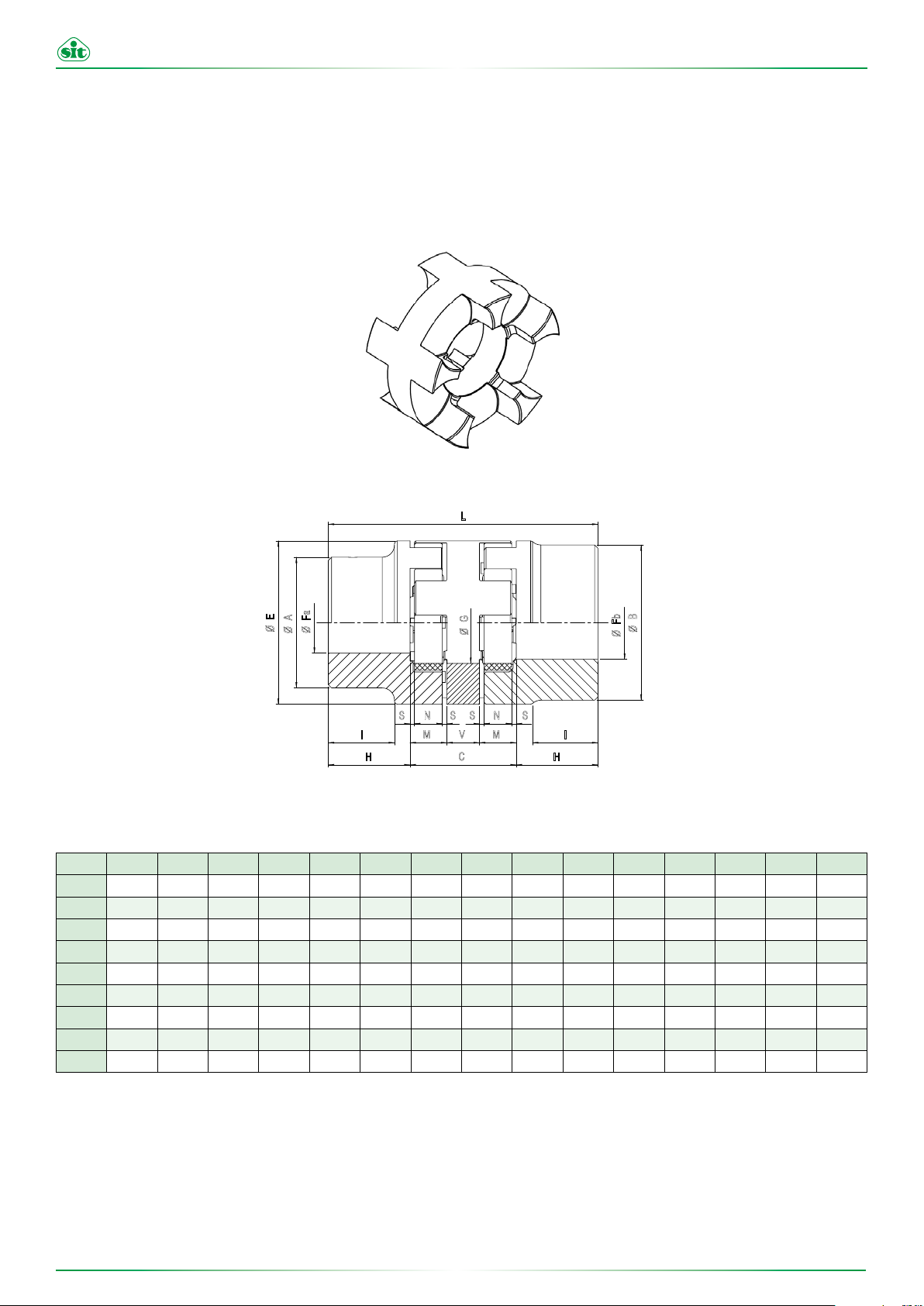
2.1.4 GRS series hubs
The GRS series hubs are intermediate elements that increase the ability of the coupling to compensate for axial, radial and angular
misalignments.
The presence of two elastic spiders allows a high damping effect of the vibrations, with consequent reduction of the transmission noise
and a reduced wear of the connected components, such as bearings.
Figure 2-3 - TRASCO® GRS series
L
E
Fa
A
Ø
Ø
Ø
S N N S
I I
H C H
Table 2.6 - DimensionsTRASCO
SIZE Fa Fb H V C M S N L E A B G ΔKr ΔKw
24/32
28/38
38/45
42/55
48/60
55/70
65/75
75/90
90/100
9-24 11-32 30 16 52 18 2 14 112 55 40 55 27 0,89 1°30’
9-28 11-38 35 18 58 20 2,5 15 128 65 48 65 30 1 1°30’
11-38 13-45 45 20 68 24 3 18 158 80 66 80 38 1,15 1°30’
11-42 13-55 50 22 74 26 3 20 174 95 75 95 46 1,26 1°30’
13-48 13-60 56 24 80 28 3,5 21 192 105 85 105 51 1,36 1°30’
16-55 16-70 65 28 88 30 4 22 218 120 98 120 60 1,52 1°30’
16-65 16-75 75 32 102 35 4,5 26 252 135 115 135 68 1,75 1°30’
16-75 16-90 85 36 116 40 5 30 286 160 135 160 80 2 1°30’
21-90 21-100 100 40 130 45 5,5 34 330 200 160 180 100 2,5 1°30’
®
GRS
G
Ø
S S
M V M
Fb
Ø
B
Ø
* dimensions in mm
114.01 - Rev. 3 - 24 April 2019 Approved by SIT S.p.A.
10

www.sitspa.com TRASCO® - Operating and Maintenance Manual
BF
A
E
H
M
V
S
P
Lc
Ea
Bc
N
S
Fa
C
D Nr
G
S
Ea
E
V
Bc
P
C
N
S
M
V
La
D Nr
G
S
Ea
E
V
Fa
A
H
I
A
G
Lb
S
N
M
V
H
Bb
I
Fa
CF
2CF
BF
A
E
H
M
V
S
P
Lc
Ea
Bc
N
S
Fa
C
D Nr
G
S
Ea
E
V
Fa
A
H
I
A
G
Lb
S
N
M
V
H
Bb
I
Fa
CF
2CF
BF
S
Ea
E
V
Fa
A
H
I
A
G
Lb
S
N
M
V
H
Bb
I
Fa
CF
BF
S
Ea
E
V
Fa
A
H
I
A
G
Lb
S
N
M
V
H
Bb
I
Fa
CF
2.1.5 GRF series hubs
The GRF series is the flange version that fits all the hubs of the TRASCO® family.
There are three different possibilities of coupling:
• Flange-flange: through the fastening bores of the flange CF (CFN in the compact version)
• Shaft-flange: on the shaft side, it is possible to install any hub of the TRASCO® family
• Shaft-shaft: with this version, it is possible to replace the flexible element without moving the hubs on the shafts or motor and driven
machine.
CF
GRMP...A
CF
CF
MF
CFF
AR
CFF
MF
La
E
G
N
S
M
V
FLANGE - FLANGE SHAFT - FLANGE SHAFT - SHAFT
Table 2.7 - Dimensioni TRASCO
Fa
SIZE
19/24
24/32
28/32
38/45
42/55
48/60
55/70
65/75
75/90
90/100
100/110
110/125
125/145
minFamax
6 19 40 65 40/32 40 50 5 4,5 18 25 26 1,5 17 8 16 2 12 32 74 49
8 24 55 80 55/40 55 65 5 4,5 27 30 31 1,5 22 8 18 2 14 34 86 56
10 28 65 100 65/48 65 80 6 6,5 30 35 36 1,5 25 10 20 2,5 15 40 100 65
12 38 80 115 66 80 95 6 6,5 38 45 46 1,5 35 10 24 3 18 44 124 79
14 42 95 140 75 95 115 6 9 46 50 51 2 38 12 26 3 20 50 138 88
15 48 105 150 85 105 125 8 9 51 56 57 2 44 12 28 3,5 21 52 152 96
20 55 120 175 98 120 145 8 11 60 65 66 2 49 16 30 4 22 62 176 111
22 65 135 190 115 135 160 10 11 68 75 76 2 59 16 35 4,5 26 67 201 126
30 75 160 215 135 160 185 10 14 80 85 87 2,5 66 19 40 5 30 78 229 144
40 90 200 260 160 200 225 12 14 100 100 102 3 80 20 45 5,5 34 85 265 165
45 115 225 285 180 225 250 12 14 113 110 112 4 85 25 50 6 38 100 295 185
55 125 255 330 200 255 290 12 18 127 120 122 4 94 26 55 6,5 42 107 321 201
55 145 290 370 230 290 325 16 18 147 140 142 5 110 30 60 7 46 120 370 230
C
Ea
D Nr
Bc
P
S
V
®
GRF
E Ea A C D
114.01 - Rev. 3 - 24 April 2019 Approved by SIT S.p.A.
E
A
Fa
Figure 2-4 - GRF TRASCO
Nr.
screws
Lc
D Nr
C
G
N
S
S
H
V
M
Ea
Bc
P
E
A
Fa
Lc
G
Bc
N
S
S
H
V
M
®
Hubs
P G H Bb Bc I V M S N La Lb Lc
11
C
P
D Nr
Ea

www.sitspa.com TRASCO® - Operating and Maintenance Manual
E
A
H
N
SS
M
V
Bc
E
Lc
Fa
D Nr
G
C
P
GRMP...A
BFN
AR
CFN
MFN
N
S
Bc
E
S
M
V V
La
D Nr
P
Fa
G
NE S S
M
V V
H
I
H
I
B
B
Bb
Lb
D Nr
G
C
P
Fa
Fa
ALBERO-FLANGIA
FLANGIA-FLANGIA
ALBERO-ALBERO
H
N
SS
M
V
Bc
E
Lc
D Nr
G
C
P
BFN
AR
CFN
MFN
NE S S
M
V V
H
I
H
I
B
B
Bb
Lb
D Nr
G
C
P
Fa
Fa
ALBERO-FLANGIA
ALBERO-ALBERO
NE S S
M
V V
H
I
H
I
B
Bb
Lb
D Nr
G
C
P
Fa
Fa
ALBERO-ALBERO
E
A
H
N
SS
M
V
Bc
E
Lc
Fa
D Nr
G
C
P
N
S S
M
V V
H
I
H
I
B
B
Bb
Lb
G
C
P
Fa
Fa
NE S S
M
V V
H
I
H
I
B
B
Bb
Lb
D Nr
G
C
P
Fa
Fa
GRMP...A
La
E
A
Fa
G
Bc
Fa
E
D Nr
P
M
S
N
V V
S
Lc
N
SS
H
M
C
G
Bc
V
E
D Nr
P
B
Fa
I
V V
H
FLANGE - FLANGE SHAFT - FLANGE SHAFT - SHAFT
Lb
NE S S
M
AR
CFN
G
Bb
I
H
BFN
MFN
B
C
Fa
D Nr
P
Table 2.8 - Dimensioni TRASCO
SIZE
19/24
24/32
28/32
38/45
42/55
48/60
55/70
65/75
75/90
90/100
100/110
110/125
125/145
Fa
minFamax
6 19 40 65 40/32 40 50 5 4,5 18 25 26 1,5 17 8 16 2 12 32 74 49
8 24 55 80 55/40 55 65 5 4,5 27 30 31 1,5 22 8 18 2 14 34 86 56
10 28 65 100 65/48 65 80 6 6,5 30 35 36 1,5 25 10 20 2,5 15 40 100 65
12 38 80 115 66 80 95 6 6,5 38 45 46 1,5 35 10 24 3 18 44 124 79
14 42 95 140 75 95 115 6 9 46 50 51 2 38 12 26 3 20 50 138 88
15 48 105 150 85 105 125 8 9 51 56 57 2 44 12 28 3,5 21 52 152 96
20 55 120 175 98 120 145 8 11 60 65 66 2 49 16 30 4 22 62 176 111
22 65 135 190 115 135 160 10 11 68 75 76 2 59 16 35 4,5 26 67 201 126
30 75 160 215 135 160 185 10 14 80 85 87 2,5 66 19 40 5 30 78 229 144
40 90 200 260 160 200 225 12 14 100 100 102 3 80 20 45 5,5 34 85 265 165
45 115 225 285 180 225 250 12 14 113 110 112 4 85 25 50 6 38 100 295 185
55 125 255 330 200 255 290 12 18 127 120 122 4 94 26 55 6,5 42 107 321 201
55 145 290 370 230 290 325 16 18 147 140 142 5 110 30 60 7 46 120 370 230
E Ea A C D
Figure 2-5 - GRF C Hubs
®
GRF
screws
P G H Bb Bc I V M S N La Lb Lc
Nr.
114.01 - Rev. 3 - 24 April 2019 Approved by SIT S.p.A.
12

www.sitspa.com TRASCO® - Operating and Maintenance Manual
2.1.6 Hubs machining
Any machining of the hubs must not compromise its functionality.
As for the maximum diameter of the bore that can be achieved, please refer to the table in the catalogue.
The bore machining must be carried out in accordance with the concentricity values with the outer diameter and the perpendicularity
values between the hole and the flat internal surface of the hub with a degree of tolerance IT8.
Figure 2-6 - Processing tolerance
It is important not to exceed, for all the materials of which the hub is composed, the maximum value of the hole provided
by SIT and reported in the technical catalogue; if this value is not respected the coupling may break, causing serious
dangers during the rotation.
DANGER!
The maximum bore allowed and indicated in the catalogue table must
not be exceeded. Higher values could cause breakage and danger
STOP
around the machine.
If the hub bore is machined by the customer, the concentricity and ra
dial oscillation values specified by SIT must be respected.
Carefully align the hubs when machining the finished bore.
CAUTION!
The customer is responsible for all the machining performed.
SIT assumes no liability arising from incorrect machining or for failure
to observe the instructions contained in this manual and in the technical
catalogue.
PRECAUTION!
Except for the machining of the hole, the seat of the keyway and the
threaded bore for the setscrew in accordance with the values shown in
the technical catalogue, any machining of couplings that must be used
in hazardous areas must obtain the express permission of SIT.
The customer must provide SIT with a technical drawing which shows
the machining to be carried out. It is the responsibility of SIT to evalua
te and approve it.
Any spare parts for these couplings must be standard hubs unbored or
with pilot bore marked with the ATEX marking.
114.01 - Rev. 3 - 24 April 2019 Approved by SIT S.p.A.
13

www.sitspa.com TRASCO® - Operating and Maintenance Manual
GRMP....A
2.1.7 Position and size of the setscrew
SIT supplies flathead setscrews class 45H according to DIN 913 for fastening the hub on the shaft.
For the position and size of the setscrews, refer to TABLE 2.9 - TRASCO®: setscrew position and to the drawing of FIGURE 2.7 - Set-
screw position.
t
P
Figure 2-7 - Setscrew position
Table 2.9 - TRASCO®: posizione grano di fissaggio
SIZE THREAD
19/24
24/32
28/38
38/45
42/55
48/60
55/70
65/75
75/90
90/100
100/110
110/125
125/145
140/160
160/185
180/200
DISTANCE
[mm]
M5 10 2
M5 10 2
M6 15 4,8
M8 15 10
M8 20 10
M8 20 10
M10 20 17
M10 20 17
M10 25 17
M12 30 40
M12 30 40
M16 35 80
M16 40 80
M20 45 140
M20 50 140
M20 50 140
THIGHTNING TORQUE
[Nm]
114.01 - Rev. 3 - 24 April 2019 Approved by SIT S.p.A.
14

www.sitspa.com TRASCO® - Operating and Maintenance Manual
2.2 Elastic spider
The elastic spider is a toothed ring produced with special polyurethane compounds that allows for optimised coupling performance
according to the application.
The flexible element is particularly resistant to ageing, hydrolysis (therefore also suitable for tropical climates), fatigue, abrasion and is
self-damping.
Figure 2-8 - Elastic spider
The operating temperature ranges of the spider is from -50 °C to +150 °C.
The standard version, is available, as standard product, in three hardness to suit different applications:
• yellow ring 92 Sh A
• red ring 98 Sh A
• green ring 64 Sh D
114.01 - Rev. 3 - 24 April 2019 Approved by SIT S.p.A.
15

www.sitspa.com TRASCO® - Operating and Maintenance Manual
2.2.1 Elastic spider performance
Table 2.10 - Elastic spider performance
SIZE COLOUR
Yellow 92 Sh A 10 20 2,7 14000
19/24
Green 64 Sh D 21 42 5,5 14000
Yellow 92 Sh A 35 70 9 10600
24/32
Green 64 Sh D 75 150 19,5 10600
Yellow 92 Sh A 95 190 25 8500
28/38
Green 64 Sh D 200 400 52 8500
Yellow 92 Sh A 190 380 49 7100
38/45
Green 64 Sh D 405 810 105 7100
Yellow 92 Sh A 265 530 69 6000
42/55
Green 64 Sh D 560 1120 145 6000
Yellow 92 Sh A 310 620 81 5600
48/60
Green 64 Sh D 655 1310 170 5600
Yellow 92 Sh A 410 820 107 4750
55/70
Green 64 Sh D 825 1650 215 4750
Yellow 92 Sh A 625 1250 163 4250
65/75
Green 64 Sh D 1175 2350 305 4250
Yellow 92 Sh A 1280 2560 333 3550
75/90
Green 64 Sh D 2410 4820 325 3550
Yellow 92 Sh A 2400 4800 624 2800
90/100
Green 64 Sh D 4500 9000 1170 2800
Yellow 92 Sh A 3300 6600 858 2500
100/110
Green 64 Sh D 6185 12370 1608 2500
Yellow 92 Sh A 4800 9600 1248 2240
110/125
Green 64 Sh D 9000 18000 2340 2240
Yellow 92 Sh A 6650 13300 1729 2000
125/145
Green 64 Sh D 12500 25000 3250 2000
140/160
160/185
180/200
HARDNESS
[Shore]
Red 98 Sh A 17 34 4,4 14000
Red 98 Sh A 60 120 16 10600
Red 98 Sh A 160 320 42 8500
Red 98 Sh A 325 650 85 7100
Red 98 Sh A 450 900 117 6000
Red 98 Sh A 525 1050 137 5600
Red 98 Sh A 680 1250 178 4750
Red 98 Sh A 950 1900 245 4250
Red 98 Sh A 1950 3900 500 3550
Red 98 Sh A 3600 7200 936 2800
Red 95 Sh A 4950 9900 1287 2500
Red 98 Sh A 7200 14400 1872 2240
Red 95 Sh A 10000 20000 2600 2000
Red 95 Sh A 12800 25600 3328 1800
Red 95 Sh A 19200 38400 4992 1500
Red 95 Sh A 28000 56000 7280 1400
RATED TORQUE
Tkn
[Nm]
MAXIMUM TORQUE
Tmax
[Nm]
VIBRATORY TORQUE
Tkw
[Nm]
MAXIMUM SPEED
[rpm]
Note: For GRB and GRCAL types it is necessary to check the transmissible torque capacity, respectively, as from the bush and clamp
114.01 - Rev. 3 - 24 April 2019 Approved by SIT S.p.A.
16

www.sitspa.com TRASCO® - Operating and Maintenance Manual
2.3 Coupling misalignments
TABLE 2.11 shows the misalignment values based on the different coupling sizes that can accomodated.
Axial misalignment Axial misalignment Axial misalignment
®
Figure 2-9 - TRASCO
Table 2.11 - TRASCO®: misalignments
: misalignments
SIZE
19/24
24/32
28/38
38/45
42/55
48/60
55/70
65/75
75/90
90/100
100/110
110/125
125/145
140/160
160/185
180/200
Note: Values valid in room temperature conditions of 20 °C and for speeds up to 1500 rpm. For other conditions, contact our Technical Department.
Axial mis. ΔKa
[mm]
1,2 1°30’ 0,20
1,4 1°30’ 0,22
1,5 1°30’ 0,25
1,8 1°30’ 0,28
2,0 1°30’ 0,32
2,1 1°30’ 0,36
2,2 1°30’ 0,38
2,6 1°30’ 0,42
3,0 1°30’ 0,48
3,4 1°30’ 0,50
3,8 1°30’ 0,52
4,2 1°30’ 0,55
4,6 1°30’ 0,60
5,0 1°30’ 0,62
5,7 1°30’ 0,64
6,4 1°30’ 0,68
Angular mis. ΔKw
[°]
Radial mis. ΔKr
[mm]
In order to guarantee a long life of the coupling, it is necessary to pay close attention to the alignment.
PRECAUTION!
In case of use in potentially explosive areas of group II with II 2GD c
marking, only half of the above indicated misalignments is allowed. If
these values are not complied with, the coupling is considered as deli
-
berately damaged.
3 Storage
The couplings must be stored in covered and dry places.
It is important that the storage areas are protected against light sources, ultraviolet lamps, mercury vapour and high electrical voltage
sources.
The moisture percentage must be maintained below 65%.
In good storage conditions the characteristics of the spiders can remain unchanged for up to 6 years.
114.01 - Rev. 3 - 24 April 2019 Approved by SIT S.p.A.
17

www.sitspa.com TRASCO® - Operating and Maintenance Manual
4 Assembling
The TRASCO® coupling is supplied unassembled, therefore it is recommended to check the presence of all the components and check
that they match the application requirements.
The characteristic of the TRASCO® family of couplings gives the possibility of mounting any hub version provided that they belong to
the same size.
As regards the hubs, the size is printed on the marking located on the lateral surface.
The size of the spider is printed on a flat surface.
ATTENTION!
Install the hubs using only with the spider provided by SIT S.p.A. and of
the same size.
SIT S.p.A. assumes no liability for malfunctions and/or failures due to incorrect assembly or that does not comply with the instructions provided
in this manual.
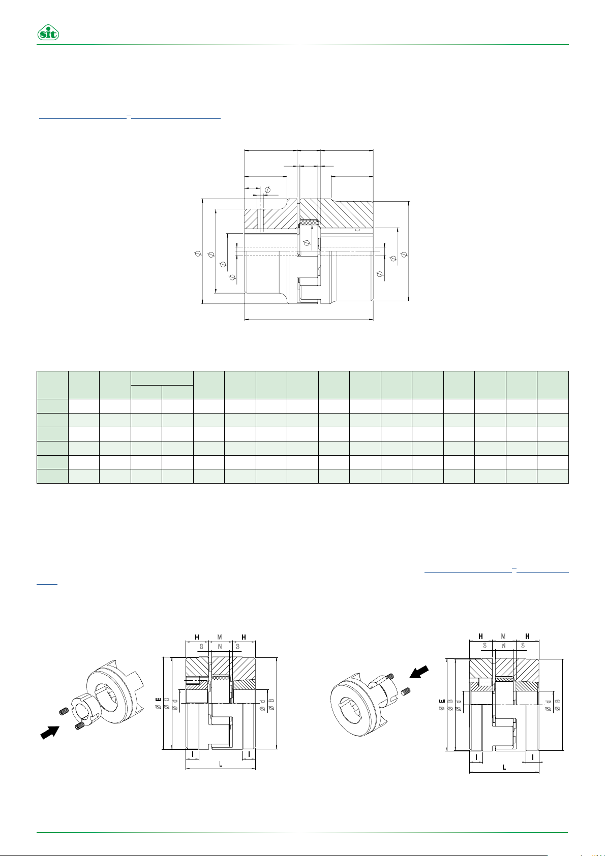
4.1 GRMP coupling assembly
Components:
• 2 hubs
• 1 elastic spider
• 2 setscrews
ATTENTION!
Before assembling SIT recommends to check that the following parts
are matching: shafts diameters, hubs bores, keyways size and their seat
on the hubs.
If the dimensions of shaft and keyway is less than the diameter of the
GRMP...A
AR
GRMP...B
Figure 4-1 - GRMP coupling
spider hole, one or both shafts may protrude into the spider.
• Install the hubs on the driving and driven shafts (see FIGURE 4.2 - GRMP: mounting)
• Insert the spider into one of the two hubs
• Check the driving and driven hub to achieve the value M (see FIGURE 4.2 and TABLE 4.1)
• If the motor and driven machine are already firmly assembled, move axially the hubs on the shafts to adjust the M dimension
• Set the hubs using the setscrews, tightening according to TABLE 2.9 - TRASCO®: SETSCREW POSITION
114.01 - Rev. 3 - 24 April 2019 Approved by SIT S.p.A.
18

www.sitspa.com TRASCO® - Operating and Maintenance Manual
Figure 4-2 - GRMP: mounting
Table 4.1 - Quote M
SIZE
19/24
24/32
28/38
38/45
42/55
48/60
55/70
65/75
75/90
90/100
100/110
110/125
125/145
140/160
160/185
180/200
QUOTE M
[mm]
16
18
20
24
26
28
30
35
40
45
50
55
60
65
75
85
PRECAUTIONS!
Be very careful in the dangerous areas.
DANGER!
STOP
Touching overheated hubs may causes burns. We recommend wearing
safety gloves.
CAUTION!
For the installation make sure that the distance M is maintained in order to ensure
that the spider can be moved axially. If this advice is disregarded, the device could
be damaged.
CAUTION!
If the dimensions of shaft and key is lower than the diameter of the spider hole,
one or both shafts may protrude into the spider.
114.01 - Rev. 3 - 24 April 2019 Approved by SIT S.p.A.
19

www.sitspa.com TRASCO® - Operating and Maintenance Manual
4.2 GRB coupling assembling
4.2.1 Taper bush mounting
Components:
• 2 hubs (B1 with bush mounting from the outside, B2 with bush mounting from the inside, FIGURE 4.3 - Types of GRB)
• 1 spider
• 2 bushes
• setscrews
B1 B2
Figure 4-3 - Types of GRB
The taper bush SER-SIT® is a clamping device with threaded holes.
Only half of the holes are in the bush, the other half are in the hub.
For correct assembling please follow these guidelines:
• Insert the bush into the hub matching the fastening holes
• Position the setscrews and tighten them partially
• Insert the whole shaft to the desired position (make sure that the M value reported in TABLE 4.1 - M Value is respected) and fully
tighten the setscrews according to the tightening torques specified in TABLE 4.2 - CONICAL CLAMPING BUSHES SETCREWS
• After a short period of operation, please check that the setscrews are not loose.
Table 4.2 - Conical clamping bushes setcrews
Taper bush size
®
SER-SIT
1108 22,3 38 2 1/4” 13 3 5,5
1610 25,4 57 2 3/8” 16 5 20
1615 38,1 57 2 3/8” 16 5 20
2012 31,8 70 2 7/16” 22 5 30
2517 44,5 85 2 1/2” 25 6 50
3535 88,9 127 3 1/2” 38 10 115
Dimensions Screws Tightening torque
L
[mm]
D
[mm]
N°
Withworth thread
[inch]
Length
[mm]
Wrench
[mm]
[Nm]
114.01 - Rev. 3 - 24 April 2019 Approved by SIT S.p.A.
20

www.sitspa.com TRASCO® - Operating and Maintenance Manual
Ø
Fa
S S
M V M
Ø
Fb
Ø
G
L
Ø
A
S N N S
I I
H C
H
Ø
B
If used in hazardous areas, it is advisable to use Loctite to prevent the
setscrews loosening.
PRECAUTION!
It is not allowed to use the taper bush without keyway in high-risk areas,
but only for category 3 equipment.
4.2.2 Taper bush disassembling
To remove the taper bush from the hub, remove the setscrews.
Then, insert one of these into the threaded hole of the bush forcing its disassembling.
4.3 GRS coupling assembling
Components:
• 2 hubs
• 2 spiders
• 1 intermediate element
• 2 setscrews
GRMP...A
AR
GRS
AR
GRMP...B
GRS
Figure 4-4 - GRS intermediate element
Follow the instructions of the GRMP type making sure to check the value M (see TABLE 4.1 - M Value) for both spiders.
114.01 - Rev. 3 - 24 April 2019 Approved by SIT S.p.A.
21

www.sitspa.com TRASCO® - Operating and Maintenance Manual
BF
CF
GRMP...A
A
E
H
M
V
S
P
Lc
Ea
Bc
N
S
Fa
C
D Nr
G
S
Ea
E
V
Bc
P
C
N
S
M
V
La
D Nr
G
S
V
Fa
A
H
I
G
Lb
S
N
M
V
CF
2CF
E
A
H
N
SS
M
V
Bc
E
Lc
Fa
D Nr
G
C
P
GRMP...A
N
S
Bc
E
S
M
V V
La
D Nr
P
Fa
G
N
S S
M
V V
H
I
B
Lb
Fa
ALBERO-FLANGIA
FLANGIA-FLANGIA
ALBERO-ALBERO
4.4 GRF coupling assembling
4.4.1 Flange-flange version
Components:
• 1 spider
• 2 flanges (CF/CFN)
CF
CF
GRFCF+AR+GRFCF GRFCFN+AR+GRFCFN
• Place the CF/CFN flanges onto the motor and the driven machine tightening the screws partially
• Tighten the screws with a torque wrench at the correct tightening torque indicated in TABLE 4.3 - GRF screws
• Place the spider onto one of the 2 flanges
• Check the driving and driven hub to achieve the value M according to TABLE 4.1 - M Value
Table 4.3 - GRF screws
SIZE No. SCREWS
19/24
24/32
28/38
38/45
42/55
48/60
55/70
65/75
75/90
90/100
100/110
110/125
125/145
Figure 4-5 - Flange-flange version (CF/CFN)
10 36° M12 120 16
10 36° M16 295 19
12 30° M16 295 20
12 30° M16 295 25
12 30° M20 580 26
16 22°30’ M20 580 30
ANGULAR SPAN OF
BORES
5 72° M5 10 8
5 72° M5 10 8
6 60° M8 41 10
6 60° M8 41 10
6 60° M8 41 12
8 45° M10 83 12
8 45° M10 83 16
BORES
ANGULAR SPAN OF
TIGHTENING TORQUE
[Nm]
[mm]
FLANGE THICKNESS “V”
114.01 - Rev. 3 - 24 April 2019 Approved by SIT S.p.A.
22

www.sitspa.com TRASCO® - Operating and Maintenance Manual
BF
A
E
H
M
V
S
P
Lc
Ea
Bc
N
S
Fa
C
D Nr
G
S
Ea
E
V
Fa
A
H
I
A
G
Lb
S
N
M
V
H
Bb
I
Fa
MF
CFF
AR
MF
CFF
CF
H
N
SS
M
V
Bc
E
Lc
Fa
D Nr
G
C
P
BFN
AR
CFN
MFN
N
E
S S
M
V V
H
I
H
I
B
B
Bb
Lb
D Nr
G
C
P
Fa
Fa
ALBERO-FLANGIA
ALBERO-ALBERO
4.4.2 Shaft-flange version
Components:
• 1 hub TRASCO
®
• 1 spider
• 1 flange (CF/CFN)
GRMP...A
GRMP...A
CF
TRASCO®+AR+GRFCF TRASCO®+AR+GRFCFN
• Install the hub on the shaft fastening with the setscrews according to TABLE 2.9 - TRASCO®: SETSCREWS POSITION
• Place the CF/CFN flanges on the motor and the driven machine tightening the screws partially
• Tighten the screws with a torque wrench at the tightening torque indicated in TABLE 4.3 - GRF Screws
• Place the spider on one of the 2 flanges
• Check the driving and driven hub to achieve the value M according to TABLE 4.1 - M Value
Figure 4-6 - Shaft-flange version (CF/CFN)
114.01 - Rev. 3 - 24 April 2019 Approved by SIT S.p.A.
23

www.sitspa.com TRASCO® - Operating and Maintenance Manual
BF
GRMP...A
S
Ea
E
V
Fa
H
I
A
G
Lb
S
N
M
V
H
Bb
I
Fa
N
E
S S
M
V V
H
I
H
I
B
Bb
Lb
D Nr
G
C
P
Fa
ALBERO-ALBERO
4.4.3 Shaft-shaft version
Components:
• 1 spider
• 2 flanges (CF/CFN)
• 2 flanged hubs (MF/MFN)
• Cylindrical head screws
• 2 setscrews
AR
MF
CFF
AR
CFF
MF
CFN
MF+GRFCF+AR+GRFCF+MF MF+GRFCFN+AR+GRFCFN+MF
Figure 4-7 - Shaft-shaft version (CF/CFN)
• install the flanged hubs on the shafts, being careful that the shafts do not protrude
• check the driving and driven hub to achieve the value M+2V (for M see TABLE 4.1 - M Value, for V see TABLE 4.3 - GRF Screws)
• fasten the flanged hubs with the setscrews according to TABLE 2.9 - TRASCO®: SETSCREW POSITION
• join together the 2 flanges (CF/CFN) and the spider, then position the assembly between the flanged hubs
• tighten the parts by hand
• tighten the screws with a torque wrench as shown in the TABLE 4.3 - GRF Screws
BFN
MFN
114.01 - Rev. 3 - 24 April 2019 Approved by SIT S.p.A.
24

www.sitspa.com TRASCO® - Operating and Maintenance Manual
5 ATEX Annex
This Annex is an integral part of the sale of the SIT TRASCO® coupling according to the ATEX Directive 2014/34/EU, contains the Declaration of Conformity, and, therefore, is delivered together with the coupling.
The User and Maintenance Manual, may be downloaded in electronic format on the website www.sitspa.com.
The analysis of the coupling machining process was carried out by SIT S.p.A.
CAUTION!
These instructions must be complied with in addition to the
warnings provided in the technical specifications.
5.1 ATEX zone classification
Below is the cross reference between hazardous zones, substances and categories according to the ATEX Directive 2014/34/EU.
Tabella 5.1 - ATEX zone classification
SUBSTANCE ZONE ZONE DESCRIPTION ATEX CATEGORY/MARKING
GASES, VAPOURS, MISTS
Zone 0
Zone 1
Zone2
Zone 20
A place in which an explosive atmosphere, consi-sting of a mixture with air of dangerous substan-ces in the form of a gas, vapour or mist,
is present continuously or for long periods or
frequently (>1000 hours/year).
A place in which an explosive atmosphere, consi-sting of a mixture of air of dangerous substances in the form of a gas, vapour or mist, is likely
to occur in normal operation occasionally (10
- 1000 hours/year).
A place in which an explosive atmosphere, consi-sting of a mixture of air of dangerous substances in the form of gas, vapour or mist, is not likely to
occur in normal operation but, if it does occur, will
persist for a short period only (<10 hours/year).
A place in which an explosive atmosphere, in
the form of a cloud of combustible dust in air
is pre-sent continuously or for long periods or
frequently (>1000 hours/year).
1G
2G or 1G
3G, 2G or 1G
1D
A place in which an explosive atmosphere, in
Zone 21
DUSTS
Zone 22
114.01 - Rev. 3 - 24 April 2019 Approved by SIT S.p.A.
the form of a cloud of combustible dust in air, is
likely to occur in normal operation occasionally
(10 - 1000 hours/year).
A place in which an explosive atmosphere, in
the form of a cloud of combustible dust in air,
is not likely to occur in normal operation but, if it
occurs, will persist for a short period only (<10
hours/year).
25
2D or 1D
3D, 2D or 1D

www.sitspa.com TRASCO® - Operating and Maintenance Manual
5.2 ATEX equipment classification
Below is the classification of equipment and protection systems according to the ATEX Directive 2014/34/EU.
Tabella 5.2 - ATEX groups and categories classification
GROUP CATEGORY RISK LEVEL PROTECTION CHARACTERISTICS OPERATING CONDITIONS
M1 Very high
GROUP I
(mining industry)
M2 High
1 Very high
GROUP II
(industry, except
mining industry)
2 High
3 Normal Suitable for normal operation.
5.3 Appropriate use of TRASCO
Two independent means of protection
or sa-fety ensured even in the event of
two faults occurring independently of
each other.
Suitable for normal operation and for
severe operating conditions. Where
appropriate, also suitable for frequent
disturbances or defects which normally
need to be taken into account.
Two independent means of protection
or sa-fety ensured even in the event of
two faults occurring independently of
each other.
Suitable for normal operating conditions
and for frequent disturbances or devices in which faults normally need to be
taken into account.
®
couplings in ATEX zones
The equipment remains connected to the
power supply and in operation even in the
presence of explosive atmospheres.
The equipment is disconnected from the
power supply in the presence of explosive
atmospheres.
The equipment remains connected to the
power supply and in operation in zones 0,
1, 2 (G) and/or 20, 21, 22 (D).
The equipment remains connected to the
power supply and in operation in zones 1, 2
(G) and/or 21, 22 (D).
The equipment remains connected to the
power supply and in operation in zones 2
(G) and/or 22 (D).
The analysis carried out by SIT S.p.A. led to the conclusion that the couplings can be used in the presence of flammable gases, vapours, mists or combustible dusts according to the following scheme:
• Gases, vapours or mists in zones 1 and 2 (not suitable for zone 0)
• Dusts in zones 21 and 22 (not suitable for zone 20)
• Equipment in group II and categories 2 and 3 (not suitable for category 1)
• Explosion group IIC, including groups IIA and IIB
• Equipment in group I and categories M2 (not suitable for category M1)
5.3.1 Gas temperature classes for Group II equipment
Tabella 5.3 - Gas temperature classes
TEMPERATURE CLASS
T1, T2, T3 150
T4 135
T5 100
T6 85
MAXIMUM SURFACE TEMPERATURE
[°C]
AMBIENT OR OPERATING TEMPERATURE
[°C]
-30°C < Ta < 120°C
-30°C < Ta < 115°C
-30°C < Ta < 80°C
-30°C < Ta < 65°C
The table indicates the temperature above which the gases, belonging to the respective class, ignite.
The ambient or operating temperature of the couplings was determined by SIT according to the characteristics of the coupling and
taking into account a safety factor equal to 20 K.
Temperature classes for Group I equipment
Couplings mounted on Group I Category M2 equipment can operate in environments with the following temperature range:
-30°C < Ta < 90°C
The coupling is not suitable for Category M1 equipment.
114.01 - Rev. 3 - 24 April 2019 Approved by SIT S.p.A.
26

www.sitspa.com TRASCO® - Operating and Maintenance Manual
5.4 Marking
SIT TRASCO® couplings are marked as required by Directive ATEX 2014/34/EU for equipment operating in zones classified for the
presen-ce of a potential hazardous atmosphere.
The marking is indelible and positioned, at SIT’s discretion, in a suitable area of the hub surface.
5.4.1 Complete marking
II 2G c IIC T6/T5/T4/T3 -30°<Ta<65°/80°/115°/120°C
II 2D c T 120°C
I M2 c -30°<Ta<90°C
SYMBOL DESCRIPTION
I/II
2
G
D
c
IIC
T6
Ta
The line regarding gases shows the temperature classes and the related admissible ambient temperature range, given the coupling
cha-racteristics and a safety factor of 20 K.
With regards to that for dusts and for Group I, only the maximum temperature is indicated, since there are no subdivisions into classes.
Group (I mining industry, II surface machine)
Category 2 (zone 1 / zone 21)
Explosive atmosphere with gases, vapours or mists
Explosive atmosphere with dust
Constructional safety
Explosion group for gases
Temperature class corresponding to a maximum surface temperature
Ambient temperature range
5.4.2 Compact marking
Where the size of the coupling does not allow complete marking, the Directive allows a reduced version which refers to this manual for
its comprehension.
II 2GD c IIC T X / I M2 c X
The letter C at the end of the marking indicates the method of protection that the user must ensure around the coupling, i.e. a bell housing type protection according to the EN 13463-5 standard.
The letter X refers to this manual which includes a summary table of the temperature class and the resulting maximum permissible
ambient temperature that must be at least 20 K less, in accordance with the elastic spider’s ability to resist.
114.01 - Rev. 3 - 24 April 2019 Approved by SIT S.p.A.
27

www.sitspa.com TRASCO® - Operating and Maintenance Manual
Z
5.5 Hub machining in ATEX environment
The machining of the bore, the seat of the keyway and the threaded bore for the fixing screw must follow the instructions provided in
the UNI-ISO 2768 standard. Any other machining on couplings to be used in hazardous zones must obtain the express consent of SIT.
The customer must provide SIT with a technical drawing showing the machining to be carried out. It is the responsibility of SIT to evaluate
and approve it.
5.6 Elastic spider check
The elastic spider must undergo periodic checks for wear.
The first check must be made after 2000 hours of operation or after 3 months from the start of use.
The next check should be made after 4000 hours or 12 months, provided that the first inspection did not show excessive wear values that
led to replacement of the elastic spider.
The check is performed using a feeler gauge to assess the wear of each element of the spider.
If the measured value (Z value) is higher than that indicated in the Z VALUE FOR CHECKING SPIDER WEAR, it is recommended to replace
the spider with an equivalent one.
Table 5.4 - Z value for checking spider wear
SIZE
19/24
24/32
28/38
38/45
42/55
48/60
55/70
65/75
75/90
90/100
100/110
110/125
125/145
140/160
160/185
180/200
QUOTE Z
[mm]
3
3
3
3
4
4
5
5
6
8
9
9
10
12
14
14
CAUTION!
Replace the elastic spider with an equivalent one of the same size.
SIT S.p.A. does not accept any liability for incorrect replacements.
For information on correct assembly, please refer to the User and
Maintenance Manual which can be downloaded in electronic format
from the website www.sitspa.com.
114.01 - Rev. 3 - 24 April 2019 Approved by SIT S.p.A.
28

www.sitspa.com TRASCO® - Operating and Maintenance Manual
5.7 Internal manufacturing check
Before marking and placing on the market, TRASCO® transmission couplings have been subjected to the checks and inspections provided
for by the internal manufacturing system and by the company’s quality system.
SIT S.p.A. has in fact obtained Certification of the Quality Management System according to international UNI EN ISO 9001 standard.
5.8 Starting
CAUTION!
All operations must be performed by trained and qualified
per-sonnel; different or additional uses to those envisaged in
this User and Maintenance Manual are not permitted.
Before placing the coupling into service, check:
• The tightening torque of the hub screws.
• The correct alignment has been achieved.
• The correct distance between the hubs.
Working in hazardous zones, tightening of the screws must be made even more securely by using Loctite (medium strength). The
user must periodically check, depending on the type of use and the substances used:
• the state of wear and correct functioning of the coupling
• the presence of vibrations and/or noise: in this case, the user must identify the causes and contact the manufacturer
For use in zones classified for the presence of combustible dust, ensure regular cleaning in order to avoid the formation of dust layers;
for this purpose, use equipment suitable for the classification of the zone.
This operation must be performed with the elements tightly coupled and in the absence of electrical voltage.
Ensure routine maintenance, according to a frequency to be determined according to the operating conditions, environment and
temperatu-re. Nevertheless, residual risks can be present during normal operation of the coupling, if:
• it is not subjected to the normal maintenance plans provided from the user and maintenance manual
• it is not used as provided in the design specifications
Different or additional uses not included in the technical specification are not permitted and SIT shall not be liable for any damage
related to unauthorised uses.
All maintenance operations must be carried out as indicated in the user and maintenance manuals: no modifications are permitted
without the written consent of SIT.
Unauthorised replacements or those using non-original parts invalidate the safety of TRASCO® couplings; all spare parts must be
obtained from SIT.
114.01 - Rev. 3 - 24 April 2019 Approved by SIT S.p.A.
29

www.sitspa.com TRASCO® - Operating and Maintenance Manual
5.8.1 Protection devices for couplings in hazardous atmospheres
Protection devices for couplings against unintended contact must be firmly attached.
Couplings for use in hazardous atmospheres must be protected by sturdy guards (if possible made of stainless steel) against falling
objects. They must be able to be easily opened and the aperture size must not exceed the following limits:
• lateral aperture: 8 mm
• upper aperture: 4 mm
The minimum distance between the mechanical guard and the rotating parts must be equal to 5 mm in all directions.
The guard must be electrically conductive within the range allowed by law and can only be removed after having isolated the machine
from the electrical supply.
Those in aluminium and NBR can be used between the pump and the electric motor only if the magnesium content is less than 7,5%.
5.8.2 Electrical continuity
TRASCO® couplings must be installed and maintained in accordance with the standards and rules of good practice for classified environ-ments against the risk of explosion due to gases, vapours and dusts.
CAUTION!
TRASCO® couplings must not be insulated from the earth;
en-sure that connection of the couplings with the earth is
always guaranteed over time.
The electrical continuity between the two metal parts of TRASCO
it is mounted (for example motor-pump).
The electrical resistance, measured between the various metallic parts of the coupling and the point of reference, must be verified at the
time of initial installation and, subsequently, during periodic checks.
®
couplings is ensured by the conductivity of the components on which
114.01 - Rev. 3 - 24 April 2019 Approved by SIT S.p.A.
30

www.sitspa.com TRASCO® - Operating and Maintenance Manual
5.9 Declaration of conformity
DECLARATION OF CONFORMITY
SIT S.p.A.
We
Viale A. Volta 2
20090 Cusago (MI)
declare under our sole responsibility that the product:
TRASCO® Coupling
to which this declaration refers,
is in conformity with the following European Directive
Directive ATEX 2014/34/UE
Such conformity has been verified based on the requirements of the
following standards or standards documents:
EN 13463-1 :2009 EN 13463-5 :2011
The technical documentation is filed with
DNV GL AS
P.O.Box 300 Veristasveien 1
1322 HOVIK
Norway
SIT S.p.A.
Cusago, 24/05/2016
114.01 - Rev. 3 - 24 April 2019 Approved by SIT S.p.A.
31
Riccardo Scaglia
Managing Director
 Loading...