


Sirius SU1, SUE1, SUE3, SU4, SU5 INSTALLATION INSTRUCTIONS
...INSTALLATION INSTRUCTIONS
INSTALLATION INSTRUCTIONS
CARE AND USE MANUAL FOR:
NOTICE D’UTILISATION ET D’ENTRETIEN POUR:
WALL RANGE HOODS
HOTTES MURALES
Models covered by this instructions: Notice d’instruction pour les modèles:
SU1 – SUE1 – SU3 – SUE3 – SU4 – SU5 – SUE5 – SU22 – SU26 SU31 – SU47-P - SU54 - SU202/SCH14 – SU 207 – SU 208
*** BEFORE INSTALLATION ***
ENSURE THERE IS NO VISIBLE OR HIDDEN DAMAGE SUSTAINED DURING SHIPPING
*** AVANT L’INSTALLATION ***
S’ASSURER QUE LES PRODUITS N’ONT SUBI AUCUN DOMMAGE PENDANT LE TRANSPORT
*** SHIPPING DAMAGE ***
MUST BE REPORTED WITHIN 5 DAYS OF RECEIPT
*** DOMMAGES DE TRANSPORT ***
DOIVENT ÊTRE NOTIFIÉS DANS LES 5 JOURS SUIVANT LA RÉCEPTION

WARNING
Thank you for purchasing a Sirius Range Hood. Please read all the instructions in this manual before installing the appliance.
Save these instructions for future reference.
Only use this appliance as an exhaust ventilation system for the removal of cooking vapors. DO NOT use to expel flammable substances or any other materials or vapors.
The installation procedures in this manual are intended for qualified installers, service technicians or persons with similar qualified background.
DO NOT attempt to install this appliance yourself.
Ensure that electrical power is turned off at source before commencing installation. All electrical wiring must be properly installed, insulated and grounded and conform to all applicable codes and standards.
Make sure all existing duct work is clean of grease build up, or duct work should be replaced, if necessary, to avoid the possibility of a grease fire. Check all joints on ductwork to ensure proper connection and all joints should be properly taped. Be careful when cutting through ceilings or walls not to damage any hidden pipes or electrical wiring. Ensure your kitchen has sufficient air return vents to replace the exhausted air.
Fan ducts should always be vented to the outside of your home and never into spaces within walls, ceilings, lofts or attics. Only use rigid, smooth steel for ducting. The exhaust point of the blower requires a 6” round connection.
2

TABLE OF CONTENTS
BEFORE YOU BEGIN |
4 |
DUCTING |
4 |
External Venting Requirements |
4 |
Duct Run Calculation |
4 |
ELECTRICAL |
5 |
Electrical Supply |
5 |
INSTALLATION |
6 |
Positioning the range hood |
6 |
Marking the fixing holes for the range hood |
6 |
Fixing the Main Support Bracket |
6 |
Chimney installation |
7 |
Hanging the range hood |
7 |
Connecting Electricity and Ducting |
7 |
Connecting Chimneys |
8 |
Connecting the screen |
9 |
Re-Circulating Requirements |
9 |
OPERATING PROCEDURES |
10 |
General Advice |
10 |
Functions |
10 |
MAINTENANCE |
12 |
Cleaning the Filter |
12 |
Cleaning the Hood |
12 |
Light Bulb Replacement |
13 |
Battery replacement |
13 |
WARRANTY |
14 |
|
|
3
BEFORE YOU BEGIN
The manufacturer declines all responsibility in the event of failure to observe the instructions given here for installation, maintenance and suitable operation of the product. The manufacturer further declines all responsibility for injury due to negligence and the warranty of the unit automatically expires due to improper maintenance and/or installation.
BEFOREYOUBEGIN:Itisadvisabletotest run the range hood before installation.
BEFORE STARTING – please read this entire document and ensure you are fully conversant with the require-ments and limitations. These units weigh approximately 125lbs and therefore require a minimum of two people to install.
DUCTING
(Not applicable if the range hood is used in recirculing model)
WARNING: Do not vent this appliance into any other ductwork, spaces between walls, ceilings, attics, garages or any other confined space.
External Venting Requirements.
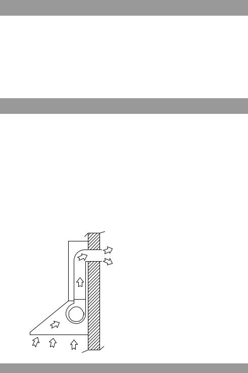
When planning new ductwork, always look for the most direct route to the outside. Venting can be done through the roof or directly through the back outside wall. (See Figure 1).
fig. 1
Only use rigid type metal ducting (plastic ducting is generally not permit-ted by code). Flexibleductingcouldrestrictairflow by up to 50%. Always fasten connections with sheet metal screws and tape all joints with certified Silver Tape or Duct Tape.
Do not use screws to fasten ductwork to the hood, only use tape as the screws will stop the dampers from opening and your hood will not work. This hood requires a 6” round duct outlet for the models with 1 motor, and 8’’ for the models with 2 motors. You can increase the duct size of the duct run but never decrease it.
Use the shortest and most direct route possible. Always, wherever reduce the number of transitions and turns with as few sharp angles as possible.
Two staggered 45 degree angles are better than one 90 degree. Make these turns as far away from the motor exhaust as possible, with as much space between each bend as possible.
Duct Run Calculation
The maximum duct run before effecting the performance of the hood is 100’. Calculate your duct run by measuring linear feet and adding the elbows, transitions and caps based on the table alongside.
4
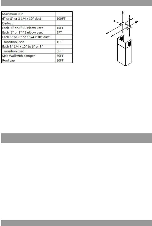
The ducting connection to the hood must be in line with the central vertical axis of the range hood 1” away from the back wall on which the hood is to be mounted. The 1” is important to enable the ceiling bracket (as shown in Figure 2) to pass behind the ductwork servicing the range hood.
fig. 2
Range hoods may interrupt the proper flow of combustion gases from fireplaces, gas furnaces and gas water heaters.
Tominimizetheriskofdrawingtheselethal gasesbackintothehome,pleasefollowthe heating equipment manufacturers safety standards and guidelines carefully.
Refer to NFPA and ASHRAE for additional information.
ELECTRICAL
WARNING: All electrical work must be performed by a qualified electrician.
Please ensure that the appropriate electrical codes or prevailing local building codes and ordinances are adhered to.
Ensure that the electricity supply is disconnected at source. Do not use an extension cord or adapter plug with this appliance.
This appliance must be grounded. Connect to a properly grounded branch circuit, protected by a 15 amp circuit breaker.
Electrical Supply.
This range hood requires a 120V, 60Hz supply and draws a maximum of 3 amps. The electrical supply to the range hood should be at least 17” from the underside of the installed range hood.
For a typical installation, where the underside of the range hood will be 30” above the counter top and the counter top is 36” above the floor level, the electrical supply should be 76” above floor level and no further than 3” to the right (as you face the wall) of the central axis of the range hood.
5

INSTALLATION
Positioning the Range Hood.
Determine the center point of the range hood. This is generally the center of the range. Make a mark on the wall a minimum of 25” above the top of an electric range. If the range is gas, the ideal minimum should be 30”.Using a spirit level, draw a perfectly vertical line, starting at the center mark, right up to the ceiling or the highest point to where the hood will extend. This is the central axis for the range hood. Draw a horizontal line fractionally above where the bottom of the range hood will be positioned. This is the underside of the range hood.
Marking the Fixing Holes for the Range Hood.
Find the marking template provided called the “Assembly Scheme”. Place the template against the wall. Align the horizontal line on the wall with the horizontal line on the template (indicated by two heavy arrows). Now align the vertical line on the wall with the “Central Axis” line on the template.
fig. 3
Gentlytapethetemplatetothewallmaking sure it has no creases or folds (use a tape that will not damage the wall finish). There are three hole positions shown for the wall bracket. Using a sharp object, mark the wall through the template at the center point of the three holes. Lower down on the template, you will see three sets of two holes. Onlytwo oftheseholes referto your model. Check which model you have and, using a sharp object, mark the two correct holes. These holes are used to anchor the range hood horizontally from inside the hood once it has been hung from the main bracket. Remove the template.
Fixing the Main Support Bracket (CAUTION: Do not drill through any utilities inside the wall).
If the range hood will be fixed to drywall we strongly recommend that you discard the wall plugs and screws supplied. These anchorsareonlysuitableforbrick/masonry applications. We suggest the use of a more appropriate anchor system specifically designed for drywall applications. Wherever possible, it is advisable to place blocking between the studs, behind the drywall, to attach the support bracket to, (refer to Figure 4).
fig. 4
Drill the appropriate size holes at the marks made earlier and fix the Support Bracket (“S”) securely to the wall. Ensure that any wall anchors have been fitted into the lower two holes, as the range hood will cover these holes once hung on the Support Bracket (“S”).
6

Before installing the hood is necessary to fix the tow motor air outlet union with the screws that are in the accessory bag.
and fix the box to the just-fit union with two screws.
Then open the upper cover of the power box
7

Only for SU202 – SU207
Fit items “C” before hanging the range hood – refer to figure 5 for positioning
fig. 5
Chimney Installation.
Locate the bracket (item Y) and position it with the vertical axis (marked on the wall earlier) running through the midpoint of bracket “Y”. This bracket fits onto the ceiling and onto the wall to secure the upper half of the decorative chimney in place. Mark the wall for the two anchors and mark the ceiling for the two anchors as indicated in Figure 2,
Fix bracket “Y - Fig.2” to the wall and ceiling.
Hanging the Range Hood.
Prepare the range hood for installation. Remove all filters to ensure they do not get damaged during the installation process. Hang the range hood on the bracket “S” (refer to Figure 6).
fig. 6
The bracket fixed onto the back of the range hood will drop into the channel on the top of bracket “S” on the wall. Ensure the hood is securely engaged into the support bracket -the range hood must clip in behind the extended lip on the Support Bracket (“S”).
“Lock” the range hood onto the “S” bracket using the four machine screws supplied (refer to Figure 7).
fig. 7
These screws are also used to make minor adjustments to the levelling of the range hood. Ensure the hood is level. Locate the two holes “C” inside the housing of the range hood and secure the range hood to the wall once the range hood is perfectly level and vertical. (refer to Figure 3).
Connecting Electricity and Ducting.
Please refer to the Electrical Supply section on page 2 for the required location of the electrical supply.
CAUTION: Make sure the power is turned off at source. Make electrical connections (refer to Figure 8).
Ensurethattheplasticflapsattheexhaust outlet for the fan move freely and have not become jammed or stuck.
8

fig. 8
Connect the appropriate length of ducting to the fan exhaust point and join up with the ducting to the exte-rior.
Figure 9 shows venting directly through the wall. Venting up and through the ceiling to the exte-rior is also possible (refer to Fig 10).
fig. 9
fig. 10
Do not fix the ducting to the range hood exhaust outlet with screws-use duct tape. Use duct tape on all joints.
Connecting Chimneys
Remove the protective covering from the decorative chimney and carefully slide the sections together. Do not remove the tape strips from inside the chimney as this protects the telescoping chim- ney-piece from scratching. Holding the two chimney sections together carefully position them over the ductwork and wiring. Position the upper chimney so that it can be fixed via the holes on the side of the ‘Y” bracket on the ceiling (refer to Figure 11).
9
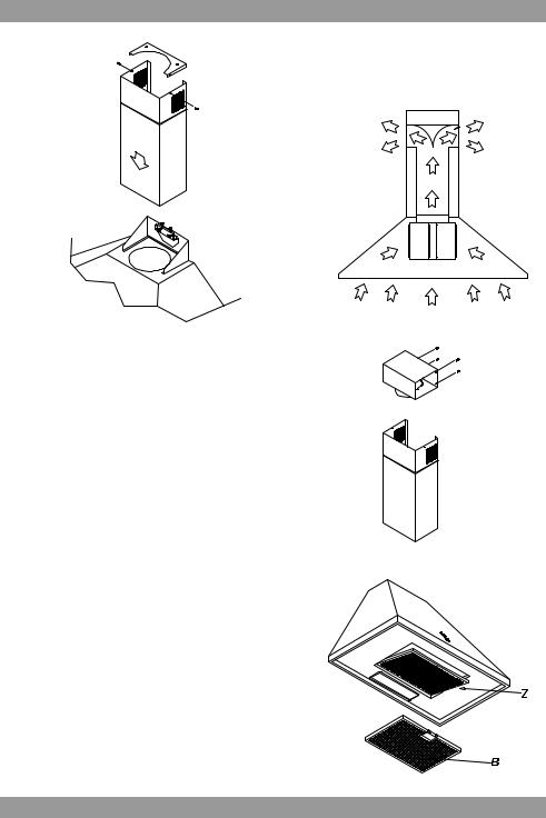
fig. 11
Connecting the Screen (SU 202 Only).
Before attaching the screen the power unit wipe the face of the flange to ensure there is no grit present – if there is this will most definitely crack the glass. The plastic washers must be positioned between the screw head and the glass. Fit the screen – please have some-one hold this in place whilst another person puts in the screws. Using FINGERS ONLY, tighten the screws evenly until finger tight. Do not under any circumstances use a screw driver.
Re-Circulating Requirements.
If the unit is to be used in the re-cir- culating mode, fit the carbon filter after the installation is complete (refer to Figure 12) fit the deflector (refer Figure 13) with the screws supplied to the upper telescope chimney. There are holes in the back upper edge of the decorative chimney for this purpose. A short length of ducting is connected between the exhaust outlet on the fan and the deflector to direct the air back into the kitchen through the vents at the top of the upper decorative chimney.
The carbon filter (supplied separately) that absorbs odors is installed behind the aluminium grease filter (refer to Fig 14).
fig. 12
fig. 13
fig. 14
10
 Loading...