

Page 1
VACUUM TUMBLER
VT-500
OWNER’S MANUAL
Page 2

SAFETY INSTRUCTIONS
WARNING TO ALL PURCHASERS, OPERATORS AND OPERATION SUPERVISORS :
MAKE CERTAIN EVERY PERSON WHO IS TO OPERATE THIS MACHINE HAS READ THIS MANUAL
BEFORE BEING PERMITTED TO OPERATE THIS MACHINE.
HAVE ALL OPERATORS SIGN THE SIGNATURE PAGE FOUND AT THE END OF THIS MANUAL.
FAILURE TO READ AND ADHERE TO THE FOLLOWING IMPROTANT INSTRUCTIONS COULD RESULT IN BODILY INJURY.
READ THIS MANUAL COMPLETELY BEFORE OPERATING
ADDITIONAL MANUALS AS WELL AS REPLACEMENT SAFETY LEBELS ARE AVAILABLE.
1. DO NOT OPERATE THIS MACHINE UNTIL IT HAS BEEN INSPECTED AND MADE READY FOR OPERATION.
2. CREATE A SECURITY PERIMETER BEFORE USING THE TUMBLER, TO PREVENT ANY POTENTIAL CAUSE OF
ACCIDENT.
3. DO NOT TOUCH MOVING PARTS.
4. DO NOT OPERATE OR WORK AROUND THIS MACHINE WITH LOOSE FITTING CLOTHING. IT COULD
BECOME ENTANGLED IN THE MACHINE
5. NEVER TRY TO MANUALLY STOP OR TURN THE TUMBLER. USE THE CONTROL TO POSITION THE TUMBLER AS
DESIRED.
6. FAILURE TO PROPERLY GROUND THIS MACHINE COULD RESULT IN ELECTRICAL SHOCK. ONLY A
QUALIFIED ELECTRICIAN WHO IS FAMILIAR WITH THE APPORPRIATE ELECTRICAL CODES SHOULD PROVIDE
THE PROPER ELECTRICAL CONNECTION.
7. DO NOT ALTER OR MODIFY THIS TUMBLER IN ANY WAY FROM ITS ORIGINAL FORM. ALLOW ONLY
AUTHORIZED PERSONAL TO SERVICE YOUR MACHINE.
8. ALWAYS TRUN OFF THE MACHINE WHEN IT IS NOT IN USE.
9. UNPLUG THE MACHINE FORM THE POWER SOURCE BEFORE REMOVING ANY PANELS OR HOUSING FOR
MAINTENANCE OR MAKING ADJUSTMENTS TO THE MACHINE.
10. ALWAYS OPERATE ON A LEVEL SURFACE.
11. KEEP UNAUTHORIZED PERSONAL AWAY FROM MACHINE.
12. THESE TUMBLERS ARE DESIGNED TO HANDLE VACUUM AND NOT PRESSURE. NOTE: DO NOT PUT
ANYTHING IN THE DRUM WHICH WOULD GENERATE A PRESSURE SUCH AS CARBON DIOXIDE SNOW OR
PELLETS
13. INSTALL THE MACHINE IN A POSITION THAT PROVIDES ADEQUATE SPACE TO ALLOW SAFE CLEARANCE
OF ANY PERSONAL IN THE AREA.
Page 3
OPERATING & PROGRAMING INSTRUCTIONS
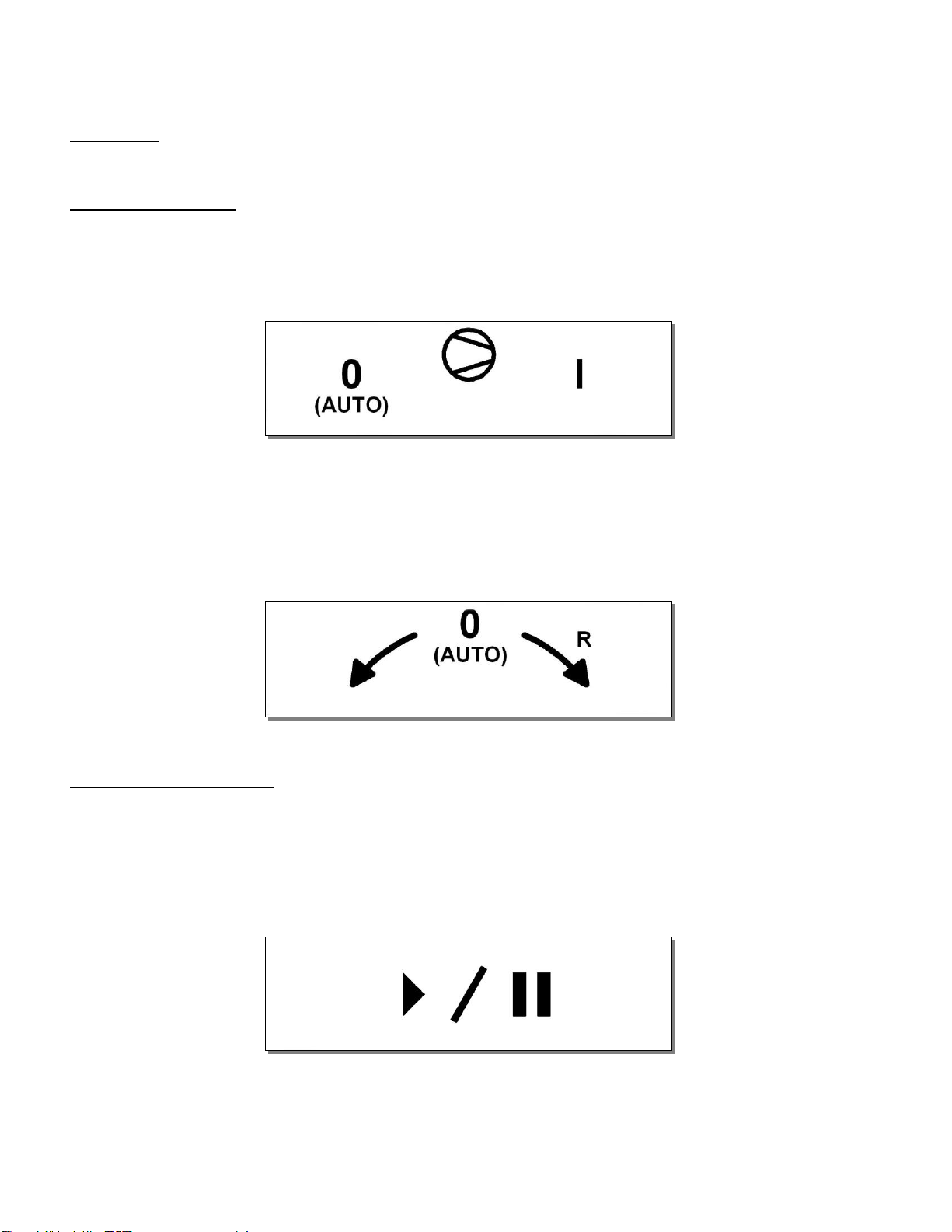
Power up:
Turn the O I selector to I position.
Manual operation:
With the O I selector to I position, you can manually start the pump and the rotation
without the PLC. Turn the pump selector to position I to start the pump, put back the
selector at position 0 to stop the pump. If the selector stays at position I the pump will
work continuously regardless of the program running.
To jog the tumbler or to make the tumbler run at 4 rpm fixed speed without the use of
the PLC (backup mode), use the rotation selector. Rotation in the R direction is for
unloading (reverse rotation). Standard rotation when operating is counterclockwise.
Turn the rotation selector to position 0 to make the rotation work accordingly with the
program.
Working with program:
Press ON/OFF to power on the tumbler. When the tumbler is energized, the
identification of the last executed program is displayed on the LCD screen. If
EMERGENCY STOP appears on the screen release the E-STOP button. Use the
start/pause push button to start the program in memory, make sure the pump selector
and the rotation selector are at position 0 (auto) before starting the program.
To change the program in memory see Activating a program in the next section. You
can manually make the vacuum inside the tumbler by activating the pump on the
remote control, stop the pump when it’s done.
Page 4

PROGRAMMING OPERATION:
The ESC key switches you between the Function Menus and Program Menus. The
SELECT key scrolls you through either the Function submenus or the Program submenus
depending on which mode you are currently in. The ENTER key allows you to access
particular functions, programs and options. Below is a list of how each menu is
organized.
FUNCTION MENUS:
F1 CREATE A PRGM
F2 DELETE A PRGM
F3 UNLOCK A PRGM
PROGRAM MENUS:
PRGRM CYCLE NAME: For example, P01: (12 character limit)
PRGRM SEGMENT #1
SEGMT TIME: 0h00
MASSAGE ON: 0h00
MASSAGE OFF: 0h00
VACUUM PUMP : OFF
SP < ************ >
PRGRM SEGMENT #2
SEGMT TIME: 0h00
MASSAGE ON: 0h00
MASSAGE OFF: 0h00
VACUUM PUMP : OFF
SP < ************ >
PRGRM SEGMENT #3
SEGMT TIME: 0h00
MASSAGE ON: 0h00
MASSAGE OFF: 0h00
VACUUM PUMP : OFF
SP < ************ >
Page 5

CREATING A PROGRAM NAME:
1. If F1 CREATE A PRGM is not displayed on the LCD screen Press ESC. Once F1
CREATE A PRGM appears press ENTER.
2. PRGM CYCLE NAME will appear on the LCD screen. Press ENTER to create a new
program name.
3. Pxx NO NAME will flash. (The program number (Pxx) will be allocated
automatically). Begin typing the program name by using the numeric keyboard;
press a numeric key until the desired character appears. Once the correct letter is
displayed press ENTER and the cursor will move one space to the right. Upon
completion of typing program name press ENTER two times. The newly typed
program name will flash. Press ENTER to confirm. Your program name has been
completed.
4. To set program features enter the program menu by pressing ESC. The newly
created program name will appear on the LCD screen. Press ENTER if the displayed
program name is the one needing to be set or modified. Or press the SELECT key to
display other pre-set programs. Once the correct program name appears press
ENTER. See setting program options below for more information.
SETTING PROGRAM OPTIONS:
Within each program three segments are available to set the tumbler times and
speeds. A complete program duration may be up to 72 hours in length (24 hours per
segment). PRGRM SEGMENT #1 can be set fro X amount of time with the MASSAGE
OFF (no rotation will occur), this can be use to draw vacuum inside the tumbler prior to
tumble. Then PRGRM SEGMENT #2 can be set for X amount of time with the MASSAGE
ON (rotation will occur) at a set RPM (rotations per minute). Perhaps after this tumbling
cycle you will want to tumble for X more amount of time but at a different speed. In
PRGRM SEGMENT #3 type this final tumbling time MASSAGE ON and at what RPM.
Depending on your tumbling needs, one two or all three of the segments may be
programmed. In short, the different cycles may be used for a pause in tumbling or
tumbling at different speed.
1. PRGRM SEGMENT #1: will appear once a program name has been selected for
modification or programming. To make changes to this segment press ENTER.
2. SEGMT TIME: 0h00 will appear. Enter the length of tumbling segment #1. Hours
must be entered in two number increments (i.e. 01, 05, 12, etc. up to 24) followed
by the minutes. In total, you must enter 4 numbers to set the tumbling cycle time.
When completed the time will flash. Press ENTER to confirm and move the next
screen.
3. MASSAGE ON: 0h00 will appear. Type the length of time you want to tumble.
Type the same time as the SEGMT TIME if tumbling is desired during this. If no time
is entered the machine will not rotate. In this case PRGRM SEGMENT #1 will act as
a timer, delaying tumbling until the next segment is activated. Press ENTER to
confirm time and/or move to the next screen.
4. MASSAGE OFF: 0h00 will appear. This option is for producers who want to
temporarily stop tumbling in a tumbling cycle. No time need be entered if a
MASSAGE ON time has been entered. If no tumbling is desired in the segment,
type the same time as SEGMT TIME. Press ENTER to confirm time or move to next
screen.
Page 6

SETTING PROGRAM OPTIONS:
5. VACUUM PUMP OFF: will appear and OFF will flash. Press the SELECT key to scroll
from OFF to ON. Press ENTER to confirm.
6. SP < ************ >will appear. Press key #4 to reduce or key #5 to increase the
speed level. Press ENTER to confirm.
7. PRGRM SEGMENT #1 will re-appear. If this is only a one-segment tumbling program
press ESC to display program name and press ENTER to begin tumbling. If
additional segments need to be set, press the SELECT key to scroll to PRGRM
SEGMENT #2 and press ENTER to set options. Same procedure applies for setting
PRGRM SEGMENT #3. Following instructions from setting PRGRM SEGMENT #1.
MODIFYING PRE-SET PROGRAM OPITONS:
1. To modify a pre-set program press ESC if in function mode (i.e. F1, F2, or F3 ).
2. When a program name appears either press ENTER if that is the program to be
modified or press the SELECT key to scroll though pre-set programs. When the
desired program appears press ENTER.
3. PRGRM SEGMENT #1 will appear. To make changes in this segment press ENTER.
4. As you press ENTER, numbers for each submenu will flash. If you want to make a
change, enter the new time or speed and press ENTER. If no changes are needed
to a time or speed press ENTER to confirm and advance you to the next submenu
screen.
5. To move onto segments #2 and/or #3 press ENTER until PRGRM SEGMENT #1
appears and press the SELECT key to scroll to other segments. Press ENTER when
desired segment appears. Repeat steps as above.
ACTIVATING A PROGRAM:
1. Press ENTER if the program name you want to run appears to activate.
2. To select a different program than the one on the screen, press the SELECT key.
3. Press ENTER after the correct program name appears.
4. The selected program will run until all segment have been completed, or the
programmed is manually stopped.
Page 7

VACUUM PUMP DAILY MAINTENANCE:
Maintenance procedure is required after each utilization of the tumbler to evacuate
water condensation inside the pump.
1. At the end of each program, close the valve between the pump and the water
separator.
2. Start and run the pump for a minimum of 20 minutes.
***IMPORTANT NOTICE; failure to do this regular maintenance could damage the
pump and void the warranty supplied by Busch Vacuum Pumps & Systems.
STOPPING A PROGRAM:
1. To interrupt a program in progress rotate the M-START button to the right. Doing so
only stops the rotation of the tumbler. The machine will remember how much
time has elapsed.
2. Rotate the M-START button to the right again to continue, if so desired.
3. Press ESC to access the function menus if you would like to clear out the program
memory from a program manually stopped before completion.
4. Press the SELECT key to scroll to F3 UNLOCK A PRGM and then press ENTER. The
name of the current program will appear.
5. Press ENTER to reset the counters. At this point another program may be
accessed.
*A program is locked from the beginning of execution through completion to prevent
any unintentional modification to the status of the current program.
DELETING A PROGRAM:
1. To delete a pre-set program form the tumbler’s memory access the function
menus and scroll to F2 DELETE A PRGM and press ENTER.
2. The first program in memory will blink. Press ENTER to delete or the SELECT key to
move to the next program.
3. Once the program needing to be deleted appears press ENTER.
4. Press ESC to unconfirmed a deflection and/or to exit the delete function.
Page 8

PROGRAM SAMPLE
OBJECTIVE :
TUMBLE CHICKEN PARTS FOR 15 MIN. AT MAX. SPEED WITH VACUUM PUMP ON.
PRESS RESULTING DISPLAY
1. On/Off Display Lights
2. ESC until F1 Create a PRGM
3. Enter PRGM Cycle name
4. Enter P01 No name (Flashing)
5. Number keypad P01 chick parts
until desired letter appears
Enter after each selection
Enter Twice Program Cycle name
6. Select PRGM SEG #1
7. Enter SEGMT TIME:0h00 (Flashing)
8. 0015 SEGMT TIME:0h15
9. Enter MASSAGE ON: 0h00
10. 0015 MASSAGE ON: 0h15
11. ENTER MASSAGE OFF: 0h00
12. ENTER VACUUM PUMP: OFF
13. SELECT VACUUM PUMP: ON
14. ENTER SP<************>
15. ENTER PRGM SEGMENT #1
16. ESC P01 CHICK
PROGRAM IS NOW COMPLETE
No other segments are necessary unless you want to change speeds during the
program. You can insert a segment at the beginning to make the vacuum inside the
tumbler without rotation.
If you make a mistake when entering, press ESC key.
Press ENTER to review program selections.
Page 9

MC-40 CONTROLS
PROGRAM SAMPLE
JOG :
Jog is also available on the PLC control. Press key pad 2 to jog forward. Press key pad
1 for continuous reverse rotation. NOTE: Wait 5 seconds after tank stops before using
jog.
TO UNLOCK A PROGRAM if programming is not responding
Push ESC until F1 Create a PRGM appears
Push SELECT until F3 Unlock a PRGM appears
Push ENTER
KEY BOARD DETAIL
Page 10

CLEANING & SANITATION
The Vacuum Tumbler drum and machine must be cleaned and sanitized daily and
whenever one marinating product is switched to another.
1. After removing all excess marinating solution, add the necessary amount of water
and mild detergent to create a solution for pre washing.
Hot water is not recommended in the first step,
as it may cause the “myosin protein” left over
from the tumbling process to build up and
discolour the inside surface of the drum
2. Fasten the cover into position and rotate the drum at full speed for approximately
two (2) minutes.
3. Use the REV button to rotate in the reverse direction for two (2) minutes.
4. Drain the cleaning solution by removing the drain plug form the clean out port .
5. Wash the inside of the drum with hot soapy water and then rinse with hot water.
6. Always lock out the power source when cleaning the tumbler except when
rotation described in step 2 and 3.
Lid gasket should be washed and sanitized in warm soapy water. Remove the
gasket from lid and clean the lid too.
7. The outside surface of the machine should also be wiped down and cleaned.
8. During cleaning of the machine, do not direct water on the controls. Instead,
wipe with a damp cloth and dry with a clean dry towel.
9. After cleaning, the machine should be sanitized with a USDA FDA approved
sanitizing solution.
Page 11

MAINTENANCE
1. Lock out energy source from the machine before doing any maintenance.
2. Check the gear reducer for oil leak montly.
3. Remove the hood cover to check condition of parts.
Page 12

OPERATOR’S SIGNATURE PAGE
My signature below attests that I have completely read and understand this manual.
I Realize that this machine, if operated carelessly, can cause serious injury to myself
and others.
Name (print) Signature Date
Page 13
DA/047
DA/044
Page 14

005D1292
ITEM PART # DESCRIPTION QT.
1 005D1293 TUMBLER PRE-ASSEMBLY 1
2 051-0740 WASHER 1/4" FLAT S/S 11
3 051-0948 BOLT M6 x 12 SS 3
4 004-0431 ELECTRICAL BOX PRE-ASSEMBLY 1
12
1
17
18
16
15
14
5 051-0190 BOLT 1/4-20 x 3/4" HEX S/S 2
6 051-0581 NUT 1/4"-20 NYLON LOCK S/S 2
7 005-0587 E-BOX COVER PRE-ASS'Y 1
8 052-0402 BOLT. HEX. 1/4"-20 NC. x 1/2" BRASS 4
9 052-0420 SCREW 1/4"-20 N.C x 3/4" PAN SLOT BRASS 6
10 102-0750 PLASTIC DRUM PLUG 3/4"NPT 1
11 005B1296 COVER ASSEMBLY 1
12 005A1303 SWIVEL JOINT ASS'Y 1
13 005A1302 WHEEL COVER ASS'Y 2
14 001A5931 CYLINDER GUARD 1
15 051-0757 WASHER 1/4" FLAT THICK S/S 6
16 051-0189 BOLT 1/4-20 x 5/8" HEX S/S 6
17 007A0146 KB-20 PUMP HOOK-UP ASS'Y 1
18 005B1326 JOG ASSEMBLY 1
19 004A3956 REAR STRUCTURE PANEL ASSEMBLY 1
DETAIL A
13
15
5
2
B
A
LET.
19
9
NEW COVER DESIGN
REDESSINÉ
MODIFICATION
A
13-11-15
12-09-10
DATE
10
SBU
SBU
INT.
4
16
2
6
11
2
8
MACHINE
VT-500
PART
VACCUM TUMBLER ASSEMBLY
ITEM
MAT.
CNC
DWG BY
APP. BY
2
SBU
7
DEPT. TOL.
USINAGE
TOLERIE
SOUDAGE
DATE
13-11-14
DATE
3
METRIC
INCH
± 0.1
±
±
0.5
0.
5
± 0.004"
±
±
N.T.S.
SIPROMAC
0.020"
0.020"
ST-GERMAIN DE GRANTHAM
QUEBEC CANADA
DEPT.
M-I
NO.
QTY.
1
005D1292
Page 15

DETAIL B
20
A
24
B
ITEM PART # DESCRIPTION QT.
23
25 002A3814 CYLINDER SPACER 1
26 004C2452 SWIVEL LEG PRE-ASS' Y 4
10
22
21
22
21
3
005D1293
ITEM PART # DESCRIPTION QT.
1 004C3620 FRAME PRE-ASS'Y 1
2 130-0064 POLYURETHANE WHEEL 5'' DIA. X 2''
3 051-0790 WASHER 1/2" FLAT S/S 4
4 003A0374 WHEEL AXIS 2
5 051-0631 NUT ½"-13nc. NYLON LOCK S/S 2
6 075-2500 PILLOW BLOCK 2 C/W EXCENT.COL 1
7 051-0800 WASHER 5/8" FLAT S/S 4
8 051-0458 BOLT 5/8"-11nc. X 2" S/S 2
9 051-0650 NUT 5/8"-11 SS 2
10 005B1295 CYLINDER ASSEMBLY 1
11 004A3629 GEARBOX ASSMBLY 1
12 051-0781 WASHER 3/8" LOCK S/S 1
13 051-0780 WASHER 3/8" FLAT S/S 1
14 051-0999 BOLT M10 x 65MM HEX S/S 1
15 051-1082 NUT M10 SS 2
16 008A1745 GEARBOX KEY 1
17 056-0437 RET.RING INT. 1-15/16'' STEEL 1
18 002A3779 GEARBOX WASHER 1
19 051-0421 BOLT 7/16"-14NC x 1-1/4" S/S 1
20 005B1300 STRUCTURE ASSEMBLY 1
21 051-0740 WASHER 1/4" FLAT S/S 16
22 051-0180 BOLT. HEX. 1/4"-20 NC. x 1/2" S/S 13
23 005A1301 SEPARATOR ASSEMBLY 1
24 051-0580 NUT 1/4"-20 S/S 3
4
THREAD
12
20
15
22
21
25
11
2
B
A
LET.
005B1295 WAS 005A1295
REDESSINÉ / AJOUT PATTE AJUSTABLE
MODIFICATION
13-11-15
12-09-10
DATE
SBU
SBU
INT.
1
7
9
NOTE:
-INSTALLER ITEM #20
AVANT D'INSTALLER ITEM #10
2
3
5
17
18
26
19
13
14
10
16
8
7
6
1
DETAIL A
MACHINE
VT-500
PART
TUMBLER PRE-ASSEMBLY
ITEM
MAT.
CNC
DWG BY
APP. BY
SBU
DEPT. TOL.
USINAGE
TOLERIE
SOUDAGE
DATE
13-11-14
DATE
METRIC
INCH
± 0.1
± 0.004"
±
0.5
±
0.020"
±
0.
5
±
0.020"
N.T.S.
DEPT.
NO.
005D1293
SIPROMAC
ST-GERMAIN DE GRANTHAM
QUEBEC CANADA
M-I
QTY.
1
Page 16

005B1296
ITEM PART # DESCRIPTION QT.
1 004B3618 COVER PRE-ASSEMBLY 1
2 008A1746 COVER GASKET 1
3 105-0436 SCREW COLLAR 1'' X 1-1/2'' X 5/8'' ALL SS 1
4 077-0601 CONICAL COMPRESSION SPRING 2.25"OD
X 1.125"OD X 3"L X 0.120"W (0.24" COMP.)
5 005A1416 LOCK BAR W/ HUB 1
1
B
NEW DESIGN
LET. MODIFICATION
3
2
1
13-11-14
DATE
SBU
INT.
4
5
MACHINE
PART
ITEM
MAT.
VT-500
COVER ASSEMBLY
CNC
DWG BY
APP. BY
SBU
DEPT. TOL.
USINAGE
TOLERIE
SOUDAGE
DATE
13-11-14
DATE
METRIC
INCH
± 0.1
± 0.004"
±
0.5
±
0.020"
±
0.
5
±
0.020"
N.T.S.
DEPT.
NO.
005B1296
SIPROMAC
ST-GERMAIN DE GRANTHAM
QUEBEC CANADA
M-I-(M)
QTY.
1
Page 17

20
005B1300
ITEM PART # DESCRIPTION QT.
16 001A5922 UPPER E-BOX SUPPORT 1
17 036-0250 GROMMET 1 1/8ID x 1 7/8OD RUBBER 1
18 179-0014 RUBBER 1/4"x3/8"x1/16"U SHAPED (0.5512) 1
19 057-0089 1/4" x 5/8"O.D. EPDM RUB. SEAL. WASHER 4
20 057-0550 PLASTIC PLUG BUTTOM 3 1/2" HOLE 1
21 036-0400 WIRE CONNECTOR 3/8'' NPT NUT 1
1
11
B
3
14
ITEM PART # DESCRIPTION QT.
1 004A3621 STRUCTURE PRE-ASS'Y 1
2 051-0740 WASHER 1/4" FLAT S/S 12
3 005-0589 REAR P.C. BOARD SUPPORT ASSEMBLY 1
4 051-0189 BOLT 1/4-20 x 5/8" HEX S/S 4
5 051-0757 WASHER 1/4" FLAT THICK S/S 4
6 051-0287 BOLT 1/4-20 x 3-1/4" S/S 4
7 058-0140 PLASTIC SPACER 0.266" x 1/2" x 2 1/4" 4
8 051-0750 WASHER 1/4" LOCK S/S 4
9 051-0580 NUT 1/4"-20 S/S 4
10 036-0400 WIRE CONNECT. 3/8'' NPT CD09/O-RING/NUT 2
11 036-0409 PRESSE-ETOUPE CD13 2
12 005B1329 FRONT P.C. BOARD SUPPORT ASSEMBLY 1
13 051-0591 NUT 1/4"-20 ACORN S/S 4
14 036-0420 PRESSE-ÉTOUPE CD21 1
15 051-0581 NUT 1/4"-20 NYLON LOCK S/S 4
7
8
9
12
2
2
16
LET.
4
18
2
4
2
15
DETAIL A
C
B
A
005A1329 NOW 005B1329
AJOUTER 036-0409 SUR DEVANT
REDESSINÉ (005A1329 ÉTAIT 005-0588)
MODIFICATION
A
4
D
17
C
19
2
15
13
10
2
DETAIL D
12-09-10
SBU
12-07-17
J.G.
12-01-10
J.G.
DATE
INT.
5
DETAIL B
MACHINE
PART
STRUCTURE ASSEMBLY
ITEM
MAT.
11
VT-500
SEE DETAIL D
6
DETAIL C
15
2
10
DEPT. TOL.
METRIC
INCH
± 0.1
± 0.004"
±
0.5
±
0.020"
±
0.
5
±
0.020"
N.T.S.
DEPT.
NO.
005B1300
SIPROMAC
ST-GERMAIN DE GRANTHAM
QUEBEC CANADA
M-I
QTY.
1
CNC
DWG BY
APP. BY
J.G.
USINAGE
TOLERIE
SOUDAGE
DATE
DATE
12-01-10
Page 18

005A1301
ITEM PART # DESCRIPTION QT.
1 004-0372 SEPARATOR SUPPORT PRE-ASS`Y 1
2 003-0106 SEPARATOR BODY 1
3 101-0870 T 3/4"NPT BR 1
4 101-0280 STRAIGHT 3/4" MNPT x 3/4" HOSE BARB 1
5 101-0945 RED. BUSH. 3/4"npt X ¼"npt. BR 1
6 114-0280 VAC GAUGE 0-30HG 1/4'' MNPT REAR
PORT(W/GLYC)
7 005A1163 FLOW STOPPER ASSEMBLY 1
2
8
8 100-0080 STREET ELBOW 3/4"npt. S/S 2
9 100-0235 CLOSE NIPPLE 3/4"npt, S/S 1
10 107-0061 BALL VALVE 3/4" NPT BRASS FOR STEAM 1
11 101-0660 ELBOW STREET 90° X 1/4'' NPT BRASS 1
1
9
12 100-0360 NIPPLE 3/4"npt. X 2" S/S 1
13 102-0904 FEMALE COUPLER 3/4'' X 3/4'' FNPT WHITE 1
14 102-0902 MALE ADAPTER 3/4'' X 3/4'' HOSE BARB
WHITE
3
4
8
10
1
1
5
B
A
LET.
REPLACE 101-0280 BY #13,14 & 15
CHANGER CERTAINE PIÈCE DE L'ASS'Y
MODIFICATION
7
12
13
14
11
6
12-03-08
11-12-15
DATE
CF
CF
INT.
MACHINE
PART
ITEM
MAT.
VT-500
SEPARATOR ASSEMBLY
CNC
DWG BY
APP. BY
J.G. (CF)
DEPT. TOL.
USINAGE
TOLERIE
SOUDAGE
DATE
11-08-17
DATE
METRIC
INCH
± 0.1
± 0.004"
±
0.5
±
0.020"
±
0.
5
±
0.020"
N.T.S.
DEPT.
NO.
005A1301
SIPROMAC
ST-GERMAIN DE GRANTHAM
QUEBEC CANADA
M-I
QTY.
1
Page 19

004A3629
ITEM PART # DESCRIPTION QT.
1 037-0944 MODULE WORM GEARBOX 1SI75 1
2 037-09215 MODULE TORQUE ARM 1SI75 1
2
1
3 037-0941 MODULE WORM GEARBOX 1SI40 1
4 037-0946 MODULE NEMA 56C MOTOR ADAPTER 1SI40 1
5 037-0936 MODULE DOUBLE WORM GEAR ADAPTER
SI40
1
LET.
MODIFICATION
5
3
4
037-0953
MOTOR 80S/4-56C, 3/4HP, 230-460V-60HZ
DATE
INT.
MACHINE
PART
ITEM
MAT.
VT-500
GEARBOX ASSMBLY
CNC
DWG BY
APP. BY
J.G.
DEPT. TOL.
USINAGE
TOLERIE
SOUDAGE
DATE
11-08-24
DATE
METRIC
INCH
± 0.1
± 0.004"
±
0.5
±
0.020"
±
0.
5
±
0.020"
N.T.S.
DEPT.
NO.
004A3629
SIPROMAC
ST-GERMAIN DE GRANTHAM
QUEBEC CANADA
M-I-(M)
QTY.
1
Page 20

2 COUPER DROIT & COLLER ENSEMBLE
PERCER 6mmØ
2 TROUS
10 TYP.
10
005A1302
ITEM PART # DESCRIPTION QT.
1 004A3622 WHEEL COVER PRE-ASS'Y 1
2 179-0150 VINYL/BUNA-N FOAM RUBBER WITH
ADHESIVE 73.5mm (0.0057)
3 057-0110 10-24 X 3/8'' BINDING POST BLACK PLAST. 2
2
26.8 ±1
3
1
LET.
MODIFICATION
DATE
INT.
MACHINE
PART
ITEM
MAT.
VT-500
WHEEL COVER ASS'Y
CNC
DWG BY
APP. BY
J.G. (CF)
DEPT. TOL.
USINAGE
TOLERIE
SOUDAGE
DATE
11-08-18
DATE
METRIC
INCH
± 0.1
± 0.004"
±
0.5
±
0.020"
±
0.
5
±
0.020"
N.T.S.
DEPT.
NO.
005A1302
SIPROMAC
ST-GERMAIN DE GRANTHAM
QUEBEC CANADA
M
QTY.
2
Page 21

007A0146
ITEM PART # DESCRIPTION QT.
1 100-0325 NIPPLE ½"npt. X 2" S/S 1
2
3
1
4
2 101-0670 ELBOW STREET 90º 1/2" NPT. BR. 1
3 108-0030 CHECK VALVE 1/2'' NPT STEAM 1
4 101-0220 STRAIGHT ½"MNPTx3/4" HOSE BARB BRASS 1
125-1020
BUSCH KB-0020 115V/1PH/60HZ
LET.
MODIFICATION
DATE
INT.
MACHINE
VT-500
PART
KB-20 PUMP HOOK-UP ASS'Y
ITEM
MAT.
CNC
DWG BY
APP. BY
CF
DEPT. TOL.
USINAGE
TOLERIE
SOUDAGE
DATE
11-12-15
DATE
METRIC
INCH
± 0.1
± 0.004"
±
0.5
±
0.020"
±
0.
5
±
0.020"
N.T.S.
DEPT.
NO.
007A0146
SIPROMAC
ST-GERMAIN DE GRANTHAM
QUEBEC CANADA
M-I
QTY.
1
Page 22

005A1303
ITEM PART # DESCRIPTION QT.
1 002-0053 SWIVEL JOINT 1
2 076-0130 "O" RING 1"I.D. x 1 3/8"O.D. x 3/16" 3
3 100-0080 STREET ELBOW 3/4"npt. S/S 1
4 100-0370 NIPPLE 3/4"npt X 6" S/S 1
5 100-0130 COUPLING 3/4" NPT SS 1
6 101-0280 STRAIGHT 3/4" MNPT x 3/4" HOSE BARB 1
2
6
LET.
MODIFICATION
5
1
4
3
DATE
INT.
MACHINE
PART
ITEM
MAT.
VT-500
SWIVEL JOINT ASS'Y
CNC
DWG BY
APP. BY
J.G. (CF)
DEPT. TOL.
USINAGE
TOLERIE
SOUDAGE
DATE
11-08-23
DATE
METRIC
INCH
± 0.1
± 0.004"
±
0.5
±
0.020"
±
0.
5
±
0.020"
N.T.S.
DEPT.
NO.
005A1303
SIPROMAC
ST-GERMAIN DE GRANTHAM
QUEBEC CANADA
M
QTY.
1
Page 23

005B1326
ITEM PART # DESCRIPTION QT.
13 026-0010 1 N.O. CONTACT WITH BASE 3
14 026-0110 BLACK CAP PUSH BUTTON (WATER) 1
15 026-0030 1 N.C. CONTACT BLOCK 2
16 026-0050 3 POSITION SELECTOR 1
17 026-0040 2 POSITION SELECTOR 1
18 026-0150 EMERGENCY BUTTON (PULL-PUSH) 1
19 026-0025 1 N.C. CONTACT WITH BASE 1
7
8
6
12
13
ITEM PART # DESCRIPTION QT.
1 004A3834 JOG PRE-ASS'Y 1
2 003A0310 CONTROL BOX (JOG) 1
3 051-0740 WASHER 1/4" FLAT S/S 8
4 051-0580 NUT 1/4"-20 S/S 4
5 051-0190 BOLT 1/4-20 x 3/4" HEX S/S 4
6 051-0111 SCREW 8-32 x 3/4" RND PHIL S/S 4
7 051-0720 WASHER #8 FLAT S/S 4
8 051-0560 NUT #8-32 NYLON LOCK S/S 4
9 001B6121 PUMP SWITCH ID. 1
10 001B6122 PUMP SWITCH ID. 1
11 001B6123 M-START SWITCH ID. 1
12 026-0020 1 N.O. CONTACT BLOCK 2
A
LET.
2
16
17
14
18
CHANGEMENT BOUTON
MODIFICATION
12-09-10
DATE
SBU
INT.
1
5
3
UTILISER DU SILICONE #169-0210 POUR SCELLER.
USE SILICON #169-0210 TO SEAL.
4
9
15
19
10
11
MACHINE
PART
ITEM
MAT.
VT-500
JOG ASSEMBLY
CNC
DWG BY
APP. BY
J.G.
DEPT. TOL.
USINAGE
TOLERIE
SOUDAGE
DATE
12-01-10
DATE
METRIC
INCH
± 0.1
± 0.004"
±
0.5
±
0.020"
±
0.
5
±
0.020"
N.T.S.
DEPT.
NO.
005B1326
SIPROMAC
ST-GERMAIN DE GRANTHAM
QUEBEC CANADA
M-(I)
QTY.
1
Page 24

004A3956
ITEM PART # DESCRIPTION QT.
1 001A5906 STRUCTURE ACCES PANEL 1
2 001A6298 EXHAUST DUCT 1
3 051-01435 SCREW 10-24 x 1/2'' HEX S/S 9
4 051-0730 WASHER #10 FLAT S/S 9
5 051-0571 NUT #10-24 S/S 9
3
1
LET. MODIFICATION
DATE
INT.
MACHINE
VT-500
PART
REAR STRUCTURE PANEL ASSEMBLY
ITEM
MAT.
CNC
DWG BY
APP. BY
J.G.
2
5USES "LOCTITE" UTILISER DU "LOCTITE"
DEPT. TOL.
METRIC
USINAGE
TOLERIE
SOUDAGE
DATE
DATE
12-12-06
INCH
± 0.1
± 0.004"
±
0.5
±
0.020"
±
0.
5
±
0.020"
N.T.S.
DEPT.
NO.
004A3956
4
SIPROMAC
ST-GERMAIN DE GRANTHAM
QUEBEC CANADA
M-I
QTY.
1
Page 25

DA/044
Page 26

L1 N GND
F1
F2
C1
C2
L1
AMPERAGE
THEORIC MESURED
WM1
GNDGND
T1
N
T2
T3
FV1
A1
B1
A2
B2
C2C1
EF1
O/L2
GRE
BLK
WHT
RED
GRE
BLK
WHT
M
WM2
M
M1
DRUM ROTATION
MOTOR
M2
VACUUM PUMP
MOTOR
A
V
A
V
A
V
A
V
F101
NOTE:
RC FILTERS
MUST BE CONNECTED
ON EACH AC COIL.
(Not shown on diagram)
4
9v
24v
TR
category
MASSAGER VT-500
system
usual
fonctions
options
3
2
1
model
F105
F104
volt.
circuit
1PH/60HZ
POWER
year month
11 10 10
drawconcept
app
DL SP DL
006-2937
SIPROMAC
day
St-Germain de Grantham
QUEBEC ,CANADA
PAGE:1 OF 3
Page 27

MC-40
OUTPUT
1
PIN3
JP3/1
2
PIN4
JP3/1
W1
(20/12)
BLK
WHT
CYCLE ON
C2
2324
O/L2
95 96
C2
VACUUM MOTOR
CONTACTOR
3
PIN5
JP3/1
4
PIN6
JP3/1
5
PIN7
JP3/1
6
PIN8
JP3/1
7
PIN1
JP3/2
8
PIN2
JP3/2
7
PIN9
JP3/1
8
PIN10
JP3/1
9
PIN11
JP3/1
10
PIN12
JP3/1
RED
GRE
ORG
PIK
BEG
YEL
BRN
PUR
GRY
E-STOP
BLU
26
27
29
category
MASSAGER VT-500
system
MC-40 OUTPUT
usual
fonctions
options
model
R4
R3
C1
YEL (24 VAC COMMON)
volt.
circuit
COMMAND
(24VAC)
1 (24VAC)
ALL
year month
11 10 10
drawconcept
DL SP DL
R4
START RELAY
R3
REVERSE RELAY
(9VAC)
3 (9VAC)
C1
FREQUENCY VAR.
CONTACTOR
SIPROMAC
day
St-Germain de Grantham
QUEBEC ,CANADA
app
006-2937
PAGE:2 OF 3
Page 28

MC-40
INPUT
1
2
3
4
JP4
BLK
RED
GRE
START/STOP
E-STOP
FULL:
ATV12
MENU
SET:
PARAMETERS SET TO:
ACC
15
DEC
DRC:
I/0:
LSP
HSP
NCR
TUNE YES DONE
TFR
R1 RUN
0.0
(2RPM@15.1HZ)
100
(9RPM@71.9HZ)
2.7
100
FUN: RRS L2H
FLT: THT-ITH 4
6
MC-40
ANALOG
OUTPUT
1
2
3
4
JP7
W104
(22/4)
BLK
WHT
RED
GRE 7
R3
12 8
R4
9 5
FREQ.
VAR.
ATV31
+10V
AI1
COM
LI2
8
10
+24V
LI1
category
MASSAGER VT-500
system
MC-40 INPUT AND ANALOG OUTPUT
usual
fonctions
options
model
volt.
circuit
COMMAND
ALL
year month
11 10 10
drawconcept
app
DL SP DL
SIPROMAC
day
St-Germain de Grantham
006-2937
QUEBEC ,CANADA
PAGE:3 OF 3
Page 29

# PART PART MACHINE MACHINE REF. QTY
SIPRO DESCRIPTION APPLICATION VOLTAGE
028-0018 TERMINAL BLOCK M6/8 ALIMENTATION 120V/1PH/60HZ VT-500 L1-N 4
028-0105 GROUND BARRIER (6 HOLES) ALIMENTATION 120V/1PH/60HZ VT-500 GRD 1
028-0060 SEPARATOR M4/6 ALIMENTATION 120V/1PH/60HZ VT-500 L1-N-GRD 2
034-0755 FUSE HOLDER 30A 1 PÔLE 600V DRIVE MOTOR 120V/1PH/60HZ VT-500 F1 1
034-0560 FUSE 25A/600V FA DRIVE MOTOR 120V/1PH/60HZ VT-500 F1 1
025-0025 CONTACTOR 1 HP IN 120V 1PH-CSA DRIVE MOTOR 120V/1PH/60HZ VT-500 C1 1
041-0017
DRIVE MOTOR 120V/1PH/60HZ VT-500 FV1 1
041-1001 EMI FILTER 4AMP 3MH, 3PH. DRIVE MOTOR 120V/1PH/60HZ VT-500 EF1 1
030-0250 CAB TIRE MOTOR 120V/1PH/60HZ VT-500 WM1 2M.
037-0953
MOTOR 80S/4-56C, 3/4HP, 230V/60HZ 2.7A
MOTOR 120V/1PH/60HZ VT-500 M1 1
034-0755 FUSE HOLDER 30A 1 PÔLE 600V PUMP 120V/1PH/60HZ VT-500 F2 1
034-0530 FUSE 20A/250V TD PUMP 120V/1PH/60HZ VT-500 F2 1
025-0030 CONTACTOR 1 HP IN 120V 1PH-CSA PUMP 120V/1PH/60HZ VT-500 C2 1
025-0190
THERMAL OVERLOAD 12 TO 18A
PUMP 120V/1PH/60HZ VT-500 O/L2 1
030-0160 CAB TIRE PUMP 120V/1PH/60HZ VT-500 WM2 2M.
125-1020 BUSCH KB-0020 115V/1PH/60HZ PUMP 120V/1PH/60HZ VT-500 M2 1
034-0740
FUSE HOLDER M4/8SF-CSA
TRANSFO 120V/1PH/60HZ VT-500 F101 1
034-0205 FUSE 5X20MM 1A/250V TIME DELAY TRANSFO 120V/1PH/60HZ VT-500 F101 1
029-0008 TRANSFO 65VA/120/24-9 TRANSFO 120V/1PH/60HZ VT-500 TR 1
034-0740
FUSE HOLDER M4/8SF-CSA
24VAC+9VAC ALL VT-500 F104+105 2
034-0210 FUSE 5X20MM 2A/250V TIME DELAY 9VAC ALL VT-500 F105 1
034-0240 FUSE 5X20MM 4A/250V TIME DELAY 24VAC ALL VT-500 F104 1
036-0740 12 CONTACTS CONNECTOR OUTPUT MC-40 ALL VT-500 1
036-0860 MTA-100 RECEPTACLE ANALOG OUTPUT MC-40 ALL VT-500 1
036-0820 0.156 CENTERLINE CRIMP HOUSING INPUT MC-40 ALL VT-500 1
036-0850 0.156 CENTERLINE CRIMP TERMIN. INPUT MC-40 ALL VT-500 4
033-0036 MICROPROCESSOR MC-40 VT MASSAGERS MC-40 ALL VT-500 1
033-0015 MEMBRANE SIPROMAC MC-40 CONTROL ALL VT-500 1
026-0240 LIGHT HEAD BODY CYCLE ON LIGHT ALL VT-500 CYCLE ON 1
026-0300 LIGHT BULB 24V CYCLE ON LIGHT ALL VT-500 CYCLE ON 1
026-0220 YELLOW LIGHT HEAD CYCLE ON LIGHT ALL VT-500 CYCLE ON 1
026-0475 ``CYCLE ON``LEGEND CYCLE ON LIGHT ALL VT-500 CYCLE ON 1
026-0025 N.C. WITH BASE EMERGENCY STOP ALL VT-500 E-STOP 1
026-0030 N.C. WITHOUT BASE EMERGENCY STOP ALL VT-500 E-STOP 1
026-0150 E. STOP BUTTON PUSH PULL EMERGENCY STOP ALL VT-500 E-STOP 1
026-0485 ``E. STOP``LEGEND EMERGENCY STOP ALL VT-500 E-STOP 1
026-0010 1 N.O. CONTACT WITH BASE STOP/START ALL VT-500 START/STOP 1
026-0110 BLACK CAP PUSH BUTTON (WATER) STOP/START ALL VT-500 START/STOP 1
026-0435 STOP-START LEGEND STOP/START ALL VT-500 START/STOP 1
025-0600 4PDT RELAY 24VAC (55.34-24VAC) REV. FOW. ALL VT-500 R3+R4 2
025-0610 4PDT RELAY SOCKET 24VAC REV. FOW. ALL VT-500 R3+R4 2
Page 30

MASSAGEUR SOUS-VIDE
VT-500
MANUEL DE L’UTILISATEUR
Page 31

AVERTISSEMENT À TOUS LES ACHETEURS, OPÉRATEURS ET SURVEILLANTS
D'OPÉRATION :
SOYEZ CERTAIN QUE CHAQUE PERSONNE QUI DOIT ACTIONNER CETTE MACHINE A LU CE MANUEL.
S`ASSURER QUE TOUS LES OPÉRATEURS ONT SIGNÉS LA PAGE DE SIGNATURE À LA FIN DE CE MANUEL.
LISEZ ET SUIVEZ LES INSTRUCTIONS SUIVANTES SINON DES BLESSURES CORPORELLES POURRAIENT SURVENIR
LISEZ CE MANUEL COMPLÈTEMENT AVANT L'UTILISATION DE L`APPAREIL.
DES MANUELS ET DES AUTOCOLLANTS DE SÉCURITÉ DE REMPLACEMENT SONT DISPONIBLE SUR
DEMANDE.
INSTRUCTIONS DE SÉCURITÉ
1. N'ACTIONNEZ PAS CETTE MACHINE JUSQU'À CE QU'ELLE AIT ÉTÉ INSPECTÉE ET NE SOIT PRÊTE POUR LE
FONCTIONNEMENT.
2. CRÉEZ UN PÉRIMÈTRE DE SÉCURITÉ AVANT D'UTILISER LE BARATTE, POUR EMPÊCHER TOUTE CAUSE
POTENTIELLE D'ACCIDENT.
4. NE TOUCHEZ PAS LES PIÈCES MOBILES.
5. NE TRAVAILLEZ PAS AUTOUR DE CETTE MACHINE AVEC DES VETEMENTS AMPLE. IL POURRAIT S`EMPÊTRÉ
DANS LA MACHINE.
6. NE JAMAIS ESSAYEZ D'ARRÊTER OU DE TOURNER MANUELLEMENT LA BARATTE. UTILISEZ LE CONTRÔLE
POUR PLACER LE BARATTE COMME DÉSIRÉ.
7. NE PAS METTRE À LA TERRE CORRECTEMENT CETTE MACHINE PEUT AVOIR COMME CONSÉQUENCE LE
CHOC ÉLECTRIQUE. SEULEMENT UN ÉLECTRICIEN QUALIFIÉ QUI CONNAÎT LE CODE ÉLECTRIQUE DEVRAIT
FAIRE LE RACCORDEMENT ÉLECTRIQUE.
8. NE CHANGEZ PAS OU NE MODIFIEZ PAS CE BARATTE DE QUELQUE FAÇON DE SA FORME ORIGINALE. NE
PERMETTEZ SEULEMENT QU` AU PERSONNEL AUTORISÉ D'ENTRETENIR VOTRE MACHINE.
9. TOUJOURS METTRE À OFF LA MACHINE QUAND ELLE N` EST PAS UTILISÉ.
10. DÉBRANCHEZ LA SOURCE D'ÉNERGIE ÉLECTRIQUE DE LA MACHINE AVANT D'ENLEVER TOUS LES
PANNEAUX POUR L'ENTRETIEN OU FAIRE DES AJUSTEMENTS À LA MACHINE.
11. OPÉREZ TOUJOURS SUR UNE SURFACE DE NIVEAU.
12. GARDEZ LE PERSONNEL NON AUTORISÉ LOIN DE LA MACHINE.
13. CES BARATTES NE SONT CONÇUES QUE POUR SUPPORTER LE VIDE ET NON LA PRESSION NOTE : NE
METTEZ RIEN DANS LA SAUMURE QUI POURRAIT PRODUIRE UNE TELLE PRESSION COMME LES GRANULES
D'ANHYDRIDE CARBONIQUE PAR EXEMPLE.
14. INSTALLEZ LA MACHINE DANS UNE POSITION QUI FOURNIT SUFFISAMENT D`ESPACE POUR PERMETTRE LE
DÉGAGEMENT SÛR DU PERSONNEL DANS LE SECTEUR.
Page 32

FONCTION ET INSTRUCTIONS DE PROGRAMMATION
Démarrage :
Tournez le sélecteur 0 I en position I.
Opération manuelle :
Avec le sélecteur 0 I en position I, il est possible de démarrer la pompe et la rotation
sans le PLC. Tourner le sélecteur de pompe en position I pour démarrer la pompe,
remettre le sélecteur en position 0 pour faire l’arrêt de la pompe. Si le sélecteur reste
en position I, la pompe fonctionnera en continue sans tenir compte du programme en
cour.
Pour tourner la barrette par à coup (JOG) ou pour faire tourner la baratte à une
vitesse fixe de 4 tours par minute sans l’aide du PLC (mode manuel), utilisez le
sélecteur de rotation. La rotation dans le sens R sert à vider la baratte (rotation à la
renverse). Le sens de rotation conventionnel pour baratter est dans le sens contraire
d’aiguilles d’une montre. Positionnez le sélecteur à la position 0 pour que la rotation
s’effectue comme programmée.
Opération avec les programmes :
Tournez le sélecteur 0 I en position I. Appuyer "ON/OFF" pour mettre en marche le
baratte. Quand la baratte est activée, l'identification du dernier programme exécuté
est affichée sur l'écran à cristaux liquides. Si l'ARRÊT d'URGENCE apparaît sur l`écran
tirer sur le bouton d'E-STOP. Utilisez le bouton poussoir démarrer/pause pour démarrer
le programme en mémoire. Assurez vous que le sélecteur de pompe et de rotation
sont positionnés à la position 0 (auto) avant de démarrer le programme.
Pour changer le programme en mémoire voir la section Lancement d’un programme
ci-après. Vous pouvez manuellement faire le vide dans la baratte en activant la
pompe sur la manette. Arrêtez la pompe lorsque le vide est atteint
Page 33

PROGRAMMATION :
ESC permet de passer du menu fonction au menu programme et vis et versa. SELECT
permet de choisir un sous menu dans le mode choisit. ENTER permet d'accéder à des
fonctions, à des programmes et à des options particulières. Ci dessous une liste de la
façon dont chaque menu est organisée.
MENUS DE FONCTION :
F1 CREATE UN PRGM
F2 DELETE A PRGM
F3 UNLCK A PRGM
MENUS DE PROGRAMME :
NOM DE CYCLE DE PRGRM : Par exemple, P01 : (limite de 12 caractères)
SEGMENT #1 DE PRGRM
SEGMT TIME : 0h00
MASSAGE ON : 0h00
MASSAGE OFF : 0h00
POMPE DE VIDE : OFF
SP < ************ >
SEGMENT #2 DE PRGRM
SEGMT TIME : 0h00
MASSAGE ON : 0h00
MASSAGE OFF: 0h00
POMPE DE VIDE : OFF
SP < ************ >
SEGMENT #3 DE PRGRM
SEGMT TIME: 0h00
MASSAGE ON : 0h00
MASSAGE OFF : 0h00
POMPE DE VIDE : OFF
SP < ************ >
Page 34

CRÉER UN NOM DE PROGRAMME :
1. Si F1 CREATE A PRGM n'est pas affiché appuyer sur ESC. Une fois que F1 CREATE A
PRGM apparaît appuyé sur la touche ENTER.
2. PRGM CYCLE NAME apparaîtra sur l'écran d'affichage à cristaux liquides. Appuyer
sur ENTER pour créer un nouveau nom de programme.
3. Pxx NO NAME clignotera. (Le numéro de programme (Pxx) sera assigné
automatiquement). Commencez à taper le nom de programme en utilisant le
clavier numérique ; appuyez sur une touche numérique jusqu'à ce que le
caractère désiré apparaisse. Une fois que la lettre correcte est afficher appuyer sur
ENTER et le curseur se déplacera d'un espace vers la droite. Pour confirmer la fin
du nom appuyer sur ENTER deux fois. Le nouveau nom de programme clignotera.
Appuyer sur ENTER pour confirmer. Votre nom de programme à été enregistré.
4. Appuyer sur ESC pour afficher le nouveau programme ou appuyer ENTER pour
modifier le programme choisit. Appuyer sur SELECT pour choisir un autre
programme déjà fait. Une fois que le nom désirer est afficher appuyer sur ENTER.
Voyez les options de programme ci-dessous pour plus d'information.
RÉGLAGE DES OPTIONS DE PROGRAMME :
Dans chaque programme trois segments sont disponibles pour choisir des temps et
des vitesses de baratte. Une durée complète de programme peut allez jusqu'à 72
heures de durée (24 heures par segment). Le SEGMENT #1 du PRGRM peut être de X
heure avec le MASSAGE OFF (aucune rotation ne se produira), peut-etre utilisé pour
faire le vide dans la baratte avant de commencer la rotation. Alors le SEGMENT #2 de
PRGRM peut être programmé avec X temps de MASSAGE ON (la rotation se produira)
à une vitesse de X RPM (rotations par minute). Peut-être après ce cycle vous voudrez
augmenter le temps ou la vitesse. Dans ce cas le SEGMENT #3 de PRGRM permet de
modifier le MASSAGE ON et de choisir une nouvelle vitesse en RPM. Selon vos besoins,
un deux ou chacun des trois des segments peut être programmé. En bref, les
différents cycles peuvent être employés pour une pause dans le barattage ou pour
barater à une vitesse différente.
1. SEGMENT #1 DE PRGRM : apparaîtra une fois qu'un nom de programme a été choisi
pour la modification ou la programmation. Pour faire des changements à cette
section de segment appuyer sur ENTER.
2. SEGMT TIME : 0h00 apparaîtra. Enter la durer du segment #1. Les heures sont entré
avec deux nombres (c.-à-d. 01, 05, 12, etc. jusqu'à 24) suivi des minutes. Au total,
vous devez écrire 4 nombres pour ajuster la durée de cycle courant. Quand le
temps entrer clignotera, appuyer sur ENTER pour confirmer et se déplacer au
prochain écran.
3. MASSAGE ON : 0h00 apparaîtra. Entrer la durée que vous voulez barater. Entrer le
même temps que le SEGMT TIME si on veut barater pendant toute la durée du
segment. Si aucun temps n'est entré la machine ne tournera pas. Dans ce cas-ci
le SEGMENT #1 de PRGRM agira en tant que temporisateur, retardant le
barattage jusqu'à ce que le prochain segment soit activé. Appuyer sur ENTER
pour confirmer le temps et/ou se déplacer au prochain écran.
4. MASSAGE OFF : 0h00 apparaîtra. Cette option est pour les utilisateurs qui veulent
cesser temporairement de barater dans un cycle. Si aucun barattage n'est désiré
Page 35

dans le segment, Entrer le même temps que le SEGMT TIME. Appuyer sur ENTER
pour confirmer le temps ou se déplacer au prochain écran.
RÉGLAGE DES OPTIONS DE PROGRAMME :
5. VACUUM PUMP OFF : apparaîtra et OFF clignotera. Appuyer sur SELECT pour choisir
entre ON ou OFF. Appuyer sur ENTER pour confirmer.
6. SP < ************ >apparaîtra. Appuyer sur #4 pour réduire ou #5 pour augmenter
le niveau de vitesse. Appuyer sur ENTER pour confirmer.
7. SEGMENT #1 DE PRGRM réapparaîtra. Si un seul segment est programmé appuyée
sur ESC pour montrer le nom de programme et appuyer sur ENTER pour
commencer à barater. Si des segments additionnels doivent être entré, Appuyer
sur SELECT pour choisir le SEGMENT #2 et appuyer sur ENTER pour enter des
valeurs. Le même procédé s'applique pour programmer le SEGMENT #3 de
PRGRM. Les mêmes Instructions que pour le SEGMENT #1 de PRGRM s`applique.
MODIFICATION D`UN PROGRAMME EXISTANT :
1. Pour modifier un programme préréglée appuyer sur ESC si en mode de fonction (c.-
à-d. F1, F2, ou F3).
2. Quand un nom de programme apparaît appuyer sur ENTER, appuyer sur SELECT pour
choisir le programme qui est à modifier et accéder au données. Quand le
programme désiré apparaît appuyer sur ENTER.
3. SEGMENT #1 DE PRGRM apparaîtra. Pour faire des changements sur ce segment
appuyez sur ENTER.
4. Après avoir appuyé sur ENTER, les données de chaque sous-menu clignoteront. Si
vous voulez faire un changement, entrer le nouveau temps ou la vitesse et
confirmer avec ENTER. Si aucun changement de temps ou de vitesse n'est pas
nécessaire appuyer sur ENTER pour confirmer et avancer au prochain écran de
sous-menu.
5. Pour passer aux segments #2 et/ou #3 appuyer jusqu'à SEGMENT #1 DE PRGRM et
appuyer sur SELECT. Appuyer sur ENTER une fois que le segment désirée apparaît.
Répétez les étapes comme ci-dessus.
LANCEMENT D'UN PROGRAMME :
1. Appuyer ENTER si le nom de programme que vous voulez est affiché.
2. Pour choisir un programme différent que celui sur l'écran, appuyé sur SELECT.
3. Appuyer START/STOP après que le programme est celui désirée.
4. Le programme choisi fonctionnera jusqu'à ce que tout le segment ait été
accompli, ou que le programme soit manuellement arrêté.
Page 36

ENTRETIEN QUOTIDIEN DE POMPE DE VIDE :
Le procédé d'entretien est exigé après chaque utilisation de la baratte pour évacuer
la condensation de l'eau à l'intérieur de la pompe.
1. À la fin de chaque programme, fermée la valve entre la pompe et le séparateur
d'eau.
2. Mettez en marche la pompe, pour 20 minutes au minimum.
*** NOTIFICATION IMPORTANTE ; le manque de faire cet entretien régulier peut
endommager la pompe et annuler la garantie fournie par le manufacturier de pompes
et des systèmes de vide Busch.
ARRÊT D'UN PROGRAMME :
1. Pour interrompre un programme en marche, tournez le sélecteur M-START vers la
droite. Ceci arrête ainsi seulement la rotation de la baratte. La machine se
rappellera combien d'heure s'est écoulée.
2. Tournez à nouveau le sélecteur M-START vers la droite pour continuer, si désiré.
3. Appuyer ESC pour accéder aux menus de fonction pour désactivée un programme
arrêter de façon manuel.
4. Appuyer sur ESC jusqu`à ce que F3 UNLOCK A PRGM apparaisse et appuyer alors
sur ENTER. Le nom du programme en cours apparaîtra.
5. Appuyer ENTER pour remettre à zéro les compteurs. A partir de ce moment un autre
programme peut être accédé.
* Un programme est verrouillé du début de l'exécution jusqu`à la fin complet pour
empêcher n'importe quelle modification involontaire du statut du programme en
cours.
SUPPRIMER UN PROGRAMME :
1. Pour supprimer un programme préréglé dans la mémoire de la baratte accéder
au menus de fonction et choisir F2 DELETE A PRGM et appuyer sur ENTER.
2. Le premier programme dans la mémoire clignotera. Appuyer sur ENTER pour
supprimer ou SELECT pour se déplacer au prochain programme.
3. Une fois que le programme devant être supprimé apparaît appuyer sur ENTER.
4. Appuyer ESC pour annuler un et/ou pour sortir du menu delete a pgm.
Page 37

EXEMPLE DE PROGRAMME
OBJECTIF :
PIÈCES DE POULET A BARRATER PENDANT 15 MN. VITESSE MAXIMUM AVEC LA
POMPE DE VIDE ON.
APPUYER AFFICHAGE RÉSULTANT
1. "ON/OFF" Voyants d'affichage
2. ESC jusqu'à F1 create a PRGM
3. ENTER Nom de cycle de PRGM
4. ENTER P01 no name (clignotant)
5. Bloc de touches de nombre P01 chick parts
Jusqu' à ce que la lettre désirée apparaît
Enter après chaque choix
Enter deux fois Programmez le nom de cycle
6. Select PRGM SEG #1
7. ENTER SEGMT TEMPS : 0h00 (clignotant)
8. 0015 SEGMT TIME : 0h15
9. Enter MASSAGE ON : 0h00
10. 0015 MASSAGE ON : 0h15
11. ENTER MASSAGE OFF : 0h00
12. ENTER POMPE DE VIDE : OFF
13. SELECT POMPE DE VIDE : ON
14. ENTER SP<************>
15. ENTER PRGM SEGMENT #1
16. ESC P01 CHICK
LE PROGRAMME EST MAINTENANT COMPLET
Aucun autre segment n'est nécessaire à moins que vous vouliez changer de vitesses
pendant le programme. Il peut être utile d’insérer un segment en début de programme
pour effectuer le vide dans la baratte avant de commencer la rotation.
Si vous faites une erreur, appuyée sur la touche ESC pour annuler.
Appuyer sur ENTER pour passer en revue les choix de programme.
Page 38

EXEMPLE DE PROGRAMME
JOG :
JOG est aussi disponible sur le PLC. Appuyer sur 2 pour pulser la rotation. Appuyer sur 1
pour une rotation continue inversée. NOTE : Attendre 5 secondes après un arrêt
complet avant d'employer le jog.
POUR UNLOCKER UN PROGRAMME :
Appuyer sur ESC jusqu'à ce que F1 créent un PRGM apparaisse
Appuyer sur SELECT jusqu'à ce que F3 unlock a PRGM apparaisse
Appuyer sur ENTER
KEYBOARD DETAIL
Page 39

NETTOYAGE ET HYGIÈNE
Le tambour de la machine à barater doit être nettoyés et aseptisé quotidiennement
ou à toutes les fois qu'un produit est changé pour un autre.
1. Après avoir enlever toute la solution de saumure, ajoutez la quantité nécessaire
d'eau et de détergent doux pour créer une solution pour le prélavage.
De l'eau chaude n'est pas recommandée dans
la première étape, comme il peut causer la
« protéine de myosine » et son accumulation
peut décolorer la surface intérieure du tambour
2. Attachez le couvert en place et faite tournez le tambour à pleine vitesse
pendant approximativement deux (2) minutes.
3. Utilisez le sélecteur REV pour faire tourner la baratte en rotation inverse pendant
approximativement deux (2) minutes.
4. Vidangez la solution de nettoyage en enlevant le bouchon de vidange.
5. Lavez l'intérieur du tambour avec de l'eau savonneuse chaude et puis rincez
avec de l'eau chaude.
6. Coupez toujours la source d'énergie pour nettoyer la BARRATTE excepter pour
l`opération décris à l`étape 2 et 3.
La garniture de couvercle devrait être lavée et aseptisée dans l'eau savonneuse
chaude. Détacher la garniture du couvercle pour facilité le nettoyage et
nettoyer aussi le couvercle.
7. La surface extérieure de la machine devrait également être essuyé et nettoyé.
8. Pendant le nettoyage de la machine, ne dirigez pas l'eau sur les commandes.
Au lieu de cela, utiliser un chiffon humide et essuyer avec une serviette sèche
propre.
9. Après nettoyage, la machine devrait être aseptisée avec une solution
d`aseptisation approuvée par le FDA de l'USDA.
Page 40

ENTRETIEN
1. Couper la source d'énergie de la machine avant de faire n'importe quel
entretien.
2. Vérifiez si il y a présence de fuite d'huile du réducteur de vitesse sur une base
mensuelle.
3. Enlevez la couverture de capot sur l'état de contrôle des pièces.
Page 41

PAGE DE SIGNATURE D'OPÉRATEUR
Ma signature ci-dessous certifie que j'ai complètement lu et comprends ce manuel.
Je me rends compte que cette machine, utilisé négligemment, peut me causer des
dommages sérieux et au autres.
Nom (copies) Signature Date
DA/047
Page 42

NOTES
 Loading...