


VACUUM PACKAGING MACHINE
MODELS 350 & 350D
OWNERS MANUAL
(MANUEL D’UTILISATION) (MANUAL DE UTILIZACIÓN)
1
2

IMPORTANT SAFETY INSTRUCTIONS
SAVE THESE INSTRUCTIONS
This symbol points out important safety instructions which, if not followed, could endanger the personal safety and/or property of yourself and others. Read and follow all instructions in this manual before attempting to operate your machine.
Failure to comply with these instructions may result in personal injury.
General Operation
•Read, understand, and follow all instructions in the manual and on the machine before starting. Keep this manual in a safe place for further and regular reference and for ordering replacement parts.
•Only allow responsible individuals familiar with the instructions to operate the machine. Be sure to know controls and how to stop the machine quickly.
•Never put your hands near moving parts.
•Only allow qualified individuals for the maintenance of your machine.
•Remove all obstacles, which may interfere with the machine functions.
•Clear the work area such as electrical wires, buckets, knives etc.
•Be sure that everyone else is clear of your work area before operating the machine.
•Do not sit nor stand on the machine.
•Always turn off the machine after your work is done. Never leave a running machine unattended.
•Always disconnect and wait till the machine has cooled before attempting any maintenance.
•Do not wear loose fitting clothes or jewelry as they may get caught in moving parts of the machine.
•Always wear security shoes, to prevent injury caused by moving the machine or objects falling from the machine.
•Never exceed the time limit to seal, which is recommended by the manufacturer. This is to avoid any damage that may be caused to the sealing bars and to eliminate the risk of fire in the machine. Thus avoiding corporal burns.
•Never touch the sealing bars after they have been used, this will avoid corporal burns. Wait a few minutes to let the machine cool down before touching.
•Always make sure that the sealing bars are well installed in their "Guide Blocks" before starting a cycle.
•Never incline the machine more than 30 degrees, it may tip over and hurt someone seriously.
•Work only in daylight or good artificial light.
•Do not operate any appliance with a damaged cord or plug, or after the appliance malfunctions or is dropped or damaged in any manner. Return appliance to the nearest authorized service facility for examination, repair, or electrical or mechanical adjustment.
Do not operate the machine while under the influence of alcohol or drugs!
3
Service
•Use proper containers when draining the oil. Do not use food or beverage containers that may mislead someone into drinking from them. Properly dispose of the containers, or store in a safe place immediately following the draining of the oil.
•Prior to disposal, determine the proper method to dispose of waste from your local office of Environmental Protection Agency. Recycling centers are established to properly dispose of materials in an environmentally safe fashion.
Do not pour oil or other fluids into the ground, down a drain or into a body of water.
 Warning-Your responsibility:
This machine should only be operated by personal who can read, understand and respect warnings and instructions regarding this machine in the owners manual. Save these instructions for future reference.
INSTALLATION NOTICE FOR MODELS:
250, 300, 350, 350D, 380 & 450T
IN ORDER TO RESPECT NSF REGULATIONS:
The table on which the machine has to be installed, should be of open frame type, to avoid dirt accumulation, and to allow easy cleaning under the machine.
4
|
VACUUM PACKAGING MACHINE |
|
MODEL 350, 350D |
|
(MC-40) |
|
GENERAL TABLE OF CONTENTS |
I |
OPERATION INSTRUCTIONS |
II |
MECHANICAL |
|
A- 350: front view assembly drawing. |
|
B- 350: rear view assembly drawing |
|
C- 350D: front view assembly drawing |
|
D- 350D: rear view assembly drawing |
|
E- 350 & 350D: front panel assembly |
|
F- Seal bar assembly drawings (twin seal) |
|
G- Seal bar assembly drawings (electrical bag cut option) |
|
H- 350: cover assembly drawing |
|
I- 350D: cover assembly drawing |
|
J- 350 & 350D: upper seal bar assembly drawing |
|
K- 350: gas injection kit installation drawing |
|
L- 350D: gas injection kit installation drawing |
III |
ELECTRICAL |
|
A- Electrical drawings |
IV |
PNEUMATIC |
|
A- Pneumatic drawing |
5
VACUUM PACKAGING MACHINES-OPERATION INSTRUCTIONS
TABLE OF CONTENTS
1.Setting up the machine
2.Electrical connection
3.Operation
3.1Working principles
3.2Special packaging
3.2.1Gas flushing
3.2.2Electrical bag cut (optional)
3.3Vacuum packaging operation
3.3.1Basics
3.3.2Functions menu
3.3.2.1Create a program
3.3.2.2Delete a program
3.3.2.3Select operating mode
3.3.3Programs menu
3.3.3.1Program identification
3.3.3.2Vacuum time setting (sensor disabled)
3.3.3.3Vacuum level setting (sensor enabled)
3.3.3.4Vacuum plus time setting (sensor enabled)
3.3.3.5Gas time setting (sensor disabled)
3.3.3.6Gas flush level setting (sensor enabled)
3.3.3.7Sealing time setting
3.3.4Vacuum cycle execution
3.3.5System monitor
3.4Daily cleaning
4.Trouble shooting
4.1Failure during a packaging cycle
4.2Insufficient vacuum
4.2.1Leakage in the bag
4.2.2No leakage in the bag
4.2.3Insufficient vacuum in the chamber
4.3Faulty seal
4.3.1Insufficient seal
4.3.2No seal
4.3.3Permanent sealing current
4.3.4Seal does not stick
4.4Fault in the valves
4.5Control board failure
5.Regular maintenance
2010-08-30
6
VACUUM PACKAGING MACHINES
1. SETTING UP THE MACHINE:
Before choosing the site for the machine, please consider that you will also need room for packaged and non-packaged products apart from the space needed for the machine itself.
Keep in mind that the machine must not be set up upon uneven ground. Especially with mobile models, the weight of the pump might then cause warping of the machine.
Then the lid will not fit correctly.
Before starting to work, check the oil view glass on the pump, if there is a sufficient quantity of oil in the pump. Never use oil other than recommended by the producer. Never exceed maximum quantity of oil indicated, when adding or changing oil. Verify weekly.
Normal ambient temperature for the vacuum pump is between 10 to 70oC.For temperature below 10oC; it is recommended to use synthetic oil. Please consult factory and pump manufacturer manual for more information or when ambient temperature are outside normal limits.
2. ELECTRICAL CONNECTION:
Electrical connections must be made by qualified personnel. This person must make sure that the electrical entries correspond to the proper voltage and amperage of the machine. GROUNDING INSTRUCTIONS: This appliance must be grounded. In the event of malfunction or breakdown, grounding provides a path of least resistance for electric current to reduce the risk of electric shock. This appliance is equipped with a cord having an equipment-grounding conductor and a grounding plug. The plug must be plugged into an appropriate outlet that is properly installed and grounded in accordance with all local codes and ordinances.
DANGER Improper connection of the equipment-grounding conductor can result in a risk of electric shock. The conductor with insulation having an outer surface that is green with or without yellow stripes is the equipment-grounding conductor. If repair or replacement of the cord or plug is necessary, do not connect the equipment-grounding conductor to a live terminal. Check with a qualified electrician or serviceman if the grounding instructions are not completely understood, or if in doubt as to whether the appliance is properly grounded. Do not modify the plug provided with the appliance if it will not fit the outlet; have a proper outlet installed by a qualified electrician.
All vacuum machines are supplied with an electrical schematic drawing. An important step in connecting the machine is to make sure that the pump turns in its correct rotation.
7
The pump should not rotate more than 3 to 4 seconds in the wrong rotation or it may cause serious damage. The proper rotation is indicated by an arrow on the pump motor.
3.OPERATION:
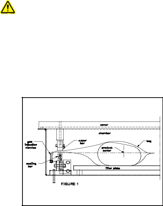
3.1Working principles:
A vacuum packaging cycle is made of 3 stages. First the vacuum is made, the air is completely taken out of the chamber and from bag containing the product. (See figure
1). Then it is possible to inject neutral gas from the nozzles, if the product is delicate. Finally, a mechanism pushes the sealing bar to the rubber support to seal the bag.
To obtain nice packages, the products and the bags have to be of proportional sizes. The bag's opening should never exceed 50 cm(2") past the seal bars. The product should be centered in height in relation to the seal bar by adjusting the spacers provided.
To obtain a good seal, make sure that no residue of fat is left between the bag's inner sides where sealing is done.
3.2 Special packaging:
8
3.2.1 Gas flushing (option):
There is an atmospheric pressure of 1 kg/ sq. cm (14 lbs/sq. inch) upon products when fully evacuated. Products which can be damaged by high pressure must be packaged with a partial vacuum, or the pressure must be counterbalance by inflating the bag with gas (nitrogen or carbon dioxide) before sealing after evacuation.
For gas flushing, the bags are placed on the sealing bars, the open end placed over the gas nozzles mounted alongside the sealing bar. After evacuation, the vacuum valve closes and the gas valve opens. Gas time (sec.) can be set in the program menu.
The necessary gas tank and pressure valve mounted on tank is not supplied, The pressure of the gas regulator should be set at approximately 1/3 kg/sq. cm
( 5 lbs/sq.inch.). Each machine has an adaptor for gas connection when gas flush option is ordered.
3.2.2 Electrical bag cut (optional):
This option is used to obtain a package that the excess bagtail is cut off close to the seal (cannot be used with top and bottom sealing).
3.3 Vacuum packaging operation:
Note: Refer to the menus structure on page 13 and the keyboard detail on page 14.
3.3.1 Basics:
Use key "POWER" to power ON / OFF the vacuum packaging machine. When the unit is energized, the identification of the last executed program is displayed on LCD screen. To disconnect, use the "POWER" key to turn off the machine , then remove plug from outlet. Do not unplug by pulling on cord. To unplug, grasp the plug, not the cord. Unplug from outlet when not in use and before servicing or cleaning.
Use the "ESC" key to change over from the programs menu to the functions menu and from the functions menu to the programs menu.
In functions menu, use key "SELECT" to select a function and key "ENTER" to accede and executed the selection.
In programs menu, use key "SELECT" to select a program and key
"ENTER" to accede and modify the selection.
In programs submenu, use key "ENTER" to pass over the parameters and point to the following one; the parameters are blinking to point out the acquisition mode. A return to programs menu is performed automatically following the last parameter acquisition.
In program submenu, use key "ESC" to get back to the programs menu. Strike any key
9
to clear the error messages which may be displayed on LCD screen.
3.3.2 Functions menu:
3.3.2.1 Create a program:
When executing the "create a program" function, the program submenu is acceded, starting with the identification. The initial identification "Pxx NO NAME" is given to the program and all parameters are established to zero; the program number is allocated automatically.
3.3.2.2 Delete a program:
When executing the "delete a program" function, the programs menu is acceded and the number of the first program in memory is blinking to point out the deletion mode. Use key "SELECT" to select a program and key
"ENTER" to accede and confirm deletion of the selection. Use key "ESC" to unconfirm a deletion and to leave the function. When leaving the function, the number of the actual program on LCD screen cease to blink.
3.3.2.3 Select operating mode:
When executing the "select operating mode" function, which is available only for the automatic units, the actual selection is blinking to point out the acquisition mode. Use key "SELECT" to get through the operating modes, which are automatic, semi-automatic and manual; the validation of the selected operating mode is performed automatically. Use key "ESC" or "ENTER" to leave the function and get back to the program menu.
3.3.3 Programs menu:
3.3.3.1Program identification:
For a selected program, set the identification, using the numeric keyboard characters chart; press numeric key until the desired character is selected (4 times for the numeric value). Use key "ENTER" to validate the character and to validate the characters string at the end(the new characters string is blinking). In a middle of an acquisition, use key "ESC" to come backward and erase one or several characters.
Example:EXAMPLE 1 |
keys 2, 2, ENTER |
|
E |
(9 characters) |
keys 8, 8, 8, ENTER |
|
X |
|
keys 1, ENTER |
|
A |
|
keys 5, ENTER |
|
M |
|
keys 6, ENTER |
|
P |
|
keys 4, 4, 4, ENTER |
|
L |
|
keys 2, 2, ENTER |
|
E |
|
keys 9, 9, 9, ENTER |
|
space |
|
keys 1, 1, 1, 1, ENTER |
|
1 |
key ENTER to validate the characters string
10
3.3.3.2 Vacuum time setting (sensor disabled):
For a selected program set the vacuum time, in seconds; the validation is automatically performed following the second digit entry (the new vacuum time is blinking). In a middle of an acquisition, use key "ENTER" to validate the vacuum time and key "ESC" to come backward and start over with a new acquisition (the old vacuum time is blinking).
Examples: 1s keys 0, 1 or 1, ENTER
15s keys 1, 5
3.3.3.3Vacuum level setting (sensor enabled)
For a selected program set the vacuum level, starting with the values; the decimal point is automatically inserted following the second digit entry and the validation is automatically performed following the third digit entry (the new vacuum level is blinking). The vacuum level is rounded off to the nearest half value. In the middle of an acquisition, use key "ENTER" to validate the vacuum level and key "ESC" to come backward and start over with a new acquisition (the old vacuum level is blinking). Set vacuum level to zero to bypass the pressure transducer and proceed only using the vacuum plus time.
Examples: 90.0% |
keys 9, |
0, 0 or |
9, |
0, |
ENTER or |
|
|
keys 9, |
0, 1 or 9, 0, |
2 or 9, 0, 3 or 9, 0, 4 |
|||
97.5% |
keys 9, |
7, 5 or |
|
|
|
|
|
keys 9, |
7, |
6 or 9, 0, |
7 or 9, 0, 8 or 9, 0, 9 |
||
0.0% |
keys 0, |
0, |
0 or 0, ENTER |
|||
3.3.3.4Vacuum plus time setting (sensor enabled)
For a selected program set the vacuum plus time, in seconds; the validation is automatically performed following the second digit entry (the new vacuum plus time is blinking). In a middle of an acquisition, use key "ENTER" to validate the vacuum plus time and key "ESC" to come backward and start over with a new acquisition (the old vacuum plus time is blinking).
Examples: 1s keys 0, 1 or 1, ENTER
15s keys 1, 5
3.3.3.5Gas time setting (sensor disabled)
For a selected program set the gas time setting following the same procedure as for the vacuum time. Keep in mind that increasing gas time decrease sealing pressure. Some vacuum must be kept inside to assure proper functioning.
11
3.3.3.6Gas flush level setting: (sensor enabled)
For a selected program set the gas flush level following the same procedure as for the vacuum level; the maximum gas flush level setting is 10% below the vacuum setting.
3.3.3.7Sealing time setting:
For a selected program set the sealing, starting with the seconds; the decimal point is automatically inserted following the first digit entry and the validation is automatically performed following the third digit entry (the new sealing time is blinking). The sealing time is truncated to the nearest half hundredth. In a middle of an acquisition, use key
"ENTER" to validate the sealing time and key "ESC" to come backward and start over with a new acquisition (the old sealing time is blinking).
Examples: 4.50s keys 4, 5, 0 or 4, 5, ENTER or
keys 4, 5, 1 or 4, 5, 2 or 4, 5, 3 or 4, 5, 4
2.35s keys 2, 3, 5 or
keys 2, 3, 6 or 2, 3, 7 or 2, 3, 8 or 2, 3, 9 0.00s keys 0, 0, 0 or 0, ENTER
3.3.4Vacuum cycle execution:
For the manual units and the automatic units set on manual, close the cover to initiate a vacuum cycle. For the automatic units set on semi-automatic or on automatic, use push button "STOP / START" to initiate or interrupt a vacuum cycle. A selected program can be initiated only in the programs menu, when no modifications are in progress, and the access to the other programs and functions is denied. During cycle execution the operation status is sequentially displayed on LCD screen, except for the parameters established to zero, which are not displayed:
-Vacuum time or vacuum % status during vacuum sequence,
-Gas time or gas % status during gas flush sequence,
-Sealing time status during sealing sequence,
-ATM message during atmosphere sequence.
During cycle execution, use key "1" to abort the vacuum sequence and execute the following sequence, which is gas flush or sealing, and key "ENTER" to accede and modify the program; the parameters become valid only for the following vacuum cycles.
3.3.5System monitor:
To accede the diagnostics menu, power up the vacuum packaging machine while keeping pushed in the "ESC"key. Use key "SELECT" to select the system monitor function and key "ENTER" to accede and visualize the monitored parameters. Use key "SELECT" to change over from the software revision, the amount of working hours done and the amount of complete cycles performed since first initialization.
12
-MENUS STRUCTURE-
•Functions menu:
"F1 CREATE A PRGM"
"F2 DELETE A PRGM"
"F3 SELECT OPMODE" (automatic units only)
• Programs menu: |
|
"Pxx NAME" |
|
Program submenu: |
|
"VACUUM: xx.x%" |
(10.0% - 99.5%) |
"VACUUM PLUS: xxs" (0s - 99s) |
|
"VACUUM: xx.xs" |
(10 – 199s) (sensor disabled in D8 menu) |
"GAS FLUSH: xx.xs" |
(0 – 99s) (units with gas option) (sensor disabled in D8) |
"GAS FLUSH: xx.x%" (0.0% - 10% below the vacuum level) (units with gas option) |
|
"SEAL TIME: x.xxs" |
(0.00s - maximum unit allocated setting) |
"Pxx NAME" |
(12 characters) |
•Diagnostics menu (keys "ESC" & "POWER" for access):
"DIAGNOSTICS MENU" (access code required)
"D1 INPUTS TEST" |
|
"D2 OUTPUTS TEST" |
|
"D3 MODEL SELECT" |
|
"D4 GAS OPTION" |
|
"D5 SEALING TIME" |
|
"D6 COOLING TIME" |
|
"D7 OFFSET CALIB” |
|
"D8 VACUUM SENSOR” |
|
"D9 SIPROMAC PUB” |
|
"D10 LOADING TIME" |
(automatic units only) |
"D11 UNLOADNG TIME" |
(automatic units only) |
"SYSTEM MONITOR" |
(no access code required) |
"SOFTWARE: R x.xx" |
|
"WORK HRS: xxxxx" |
|
"CYCLES: xxxxxxx" |
|
13
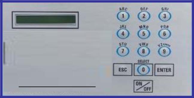
-KEYBOARD DETAILS-
MC-40 CONTROLS
MC-40 CONTROLS
14

WARNING: All electrical work described in this brochure should be done by a QUALIFIED and AUTHORIZED technician.
3.4Daily cleaning
For hygienic cleanliness, it is imperative to clean chamber and spacers daily. Also clean the lid rubber to assure tight seat of the lid.
Cleaning instructions for gas injection nozzles: Periodically on a regular basis the gas injection nozzles must be removed with the connection tube and soaked in a food grade soap and water solution, then dried and re-installed.
4.TROUBLE SHOOTING:
4.1Failure during packaging cycle:
4.1.1 "COVER DOWN ERROR" message is displayed on LCD(manual units):
The input signal of the down position switch has been lost during cycle execution.
-Check limit switch adjustment.
4.2Insufficient vacuum:
4.2.1Leakage in the bag:
Most frequently, insufficient vacuum in bags is due to leakage in bag and not due to any fault of the machine.
Pin-hole leak for which there is no obvious explanation is due to faulty bag material.
Pin-hole leak caused by sharp edge of the product (bone, etc.).Use bone-guard or thicker film.
Tear in bag by careless handling (sharp edge on filling table, damage made by retailer or customer).
Leakage in lateral or bottom seal, complain to supplier of bags or film.
4.2.2No leakage in the bag:
Bag is too large, therefore the surplus of air remains visible (there is surplus of air in 0.4% of the bag volume in each bag). Use bags of suitable size.
Vacuum time is too short:
Pressure bar is jammed and closes opening of bag during evacuation.
4.2.3Insufficient vacuum in chamber:
If troubles described under 4.2.1 and 4.2.2 do not apply, there is something wrong with the evacuation. To find the leakage quickly, check for leaks with a precision
15
vacuumeter, going back step by step from the chamber to the pump.
At the chamber (measuring point at base of valve) at maximum time of evacuation. If more than 6 torr, proceed directly to the pump, if more than 3 torr: have pump service by pump supplier. If pressure at pump is good, reconnect hoses to pump and measure again.
Verify at vacuum hose connections and valve connections.
When proceeding this way, starting from pump, loss of pressure per step must not exceed 0.5 to 1 torr.
Warning: Verify connections of measuring equipment before verifying machine.
Most frequent points of leakage: lid gasket, damaged vacuum hose or loose hose clamps.
4.3Faulty seal:
4.3.1Insufficient seal:
Damaged teflon or silicone rubber.
Sealing pressure too low, bellows leaking or pressure bar jammed.
Leakers in seal: heating wire mechanically damaged (knicked) or silicone rubber uneven.
4.3.2No seal:
Sealing wire burnt.
Faulty contact in sealing circuit.
Sealing transformer burnt through.
Contactor does not work.
4.3.3Permanent sealing current:
Contactor is jammed check sealing transformer for damage through overload.
4.3.4Seal does not stick:
Insufficient layer of polyethylene (inferior quality of bags).
Seal area extremely contaminated by fat or meat juice. Use filling aid.
Sealing temperature is too low (when using very thick films).
Warning: Do not increase sealing time more than really necessary; higher temperature will reduce working life of teflon and silicone rubber.
4.4Fault in the valve:
Vacuum or air valve does not open.
16
Check whether there is voltage on the magnetic valves during their period of operation.
If there is no voltage a wire is broken or the PC board is damaged.
Lid does not open at the end of the cycle; air enters, but there is still 20 - 40% vacuum in chamber. Vacuum valve does not close.
4.5MC40 Control board failure
NOTE: Refer to menu structure on page 13.
This board software is allowing access to a "Diagnostics Menu". Only qualified service technicians are authorized to access this menu by entering a security password.
By acceding either the "D1 input test" feature or the "D2 output test" feature, a trained technician will be able to quickly know the origin of the problem: pump,
sealing system, pneumatic problem, security switches problem, etc...
Keep in mind that in most cases trouble is due to a leakage, loose electrical Keynesian or evident damage to the main component: vacuum pump, valves..., electrical contactors, thermal overload, fuses holder or transformer.
For assistance do not hesitate to contact your local service technicians.
5.Regular maintenance:
Routine controls to be made at regular intervals: Check teflon for wear.
Check silicone rubber for burnt spots and smooth even position.
Check pressure bar for jamming.
Check lid sealing for damage and hardened spots. Check switch-point of micro switch, adjust if necessary.
Check evacuation hose for damage (contraction of diameter, or abrasions). Check vacuum connections for tightness.
Check oil in pump (oil level in view glass; add if necessary. Regular change of oil - necessity indicated by change of color).
Check vacuum in chamber with precision vacuumeter. Check function of cycle with various settings of timers.
17

004A4142
2
3
8 9 19
17


 14 5 7


6
12
1
1120 21
8 10
13
ITEM |
PART # |
DESCRIPTION |
QT. |
1 |
004B0229 |
VACUUM PRE-ASSEMBLY |
1 |
|
|
|
|
2 |
005B0266 |
COVER ASSEMBLY |
1 |
|
|
|
|
3 |
004A1224 |
SPRING PRE-ASSEMBLY |
2 |
|
|
|
|
4 |
005E0832 |
MC-40 FRONT PANEL ASSEMBLY |
1 |
|
|
|
|
5 |
004A4144 |
VALVE ASSEMBLY VACCUM SENSOR |
1 |
|
|
|
|
6 |
004A4133 |
VALVE ASSEMBLY PUMP |
1 |
|
|
|
|
7 |
004C3857 |
REAR PANNEL PRE-ASS'Y |
1 |
|
|
|
|
8 |
051-0740 |
WASHER 1/4" FLAT S/S |
8 |
|
|
|
|
9 |
051-0581 |
NUT 1/4"-20 NYLON LOCK S/S |
4 |
10 |
051-0930 |
BOLT M6 x 10 S/S |
4 |
|
|
|
|
11 |
004A4112 |
NSF FOOT |
4 |
|
|
|
|
12 |
004A3374 |
LIMIT SWITCH ASS'Y |
1 |
|
|
|
|
13 |
004-0042 |
ELEC. SUPPORT PRE-ASS'Y |
1 |
|
|
|
|
14 |
036-0400 |
WIRE CONNECT. 3/8'' NPT |
2 |
|
|
CD09/O-RING/NUT |
|
|
|
|
|
15 |
036-0200 |
GROMMET 5/8"IDx1 1/8"OD RUBBER |
1 |
|
|
|
|
16 |
036-0390 |
CABLE CONNECT.3/8"-1/2"METAL |
1 |
|
|
|
|
17 |
005-0532 |
BELLOWS ASSEMBLY |
1 |
|
|
|
|
18 |
002-0029 |
LEFT SEAL BAR GUIDE BLOCK |
1 |
|
|
|
|
19 |
002-0030 |
RIGHT SEAL BAR GUIDE BLOCK |
1 |
|
|
|
|
20 |
005A0278 |
FILLER PLATE ASS'Y |
1 |
|
|
|
|
21 |
005A0364 |
HALF FILLER PLATE ASS'Y |
2 |
|
|
|
|
22 |
005A1584 |
MC-40 FRONT PANEL ASSEMBLY (BERKEL) |
1 |
22 BERKEL
4
|
|
|
|
|
MACHINE |
350 |
|
|
|
|
DEPT. TOL. |
METRIC |
INCH |
SIPROMAC |
||||||||||
|
|
|
|
|
|
|
|
|
|
|
TOLERIE |
± 0.5 |
|
± 0.020" |
||||||||||
|
|
|
|
|
|
|
|
|
|
|
|
USINAGE |
± 0.1 |
|
± 0.004" |
|
|
|||||||
|
|
|
|
|
|
|
|
|
|
|
|
SOUDAGE |
± 0.5 |
|
± 0.020" |
ST-GERMAIN DE GRANTHAM |
||||||||
|
|
|
|
|
PART |
|
|
|
|
|
||||||||||||||
|
|
|
|
|
|
|
MACHINE ASSEMBLY |
|
|
|
|
|
|
|
|
N.T.S. |
QUEBEC CANADA |
|||||||
|
|
|
|
|
|
|
|
|
|
|
|
|
|
|
|
|
||||||||
|
|
|
|
|
|
|
|
|
|
|
|
|
|
|
|
|
|
|
|
|
|
|
|
|
|
|
|
|
|
ITEM |
|
|
CNC |
|
|
|
|
|
|
|
|
|
|
|
DEPT. |
M |
QTY. |
||
|
|
|
|
|
|
|
|
|
|
|
|
|
|
|
|
|
|
|
|
|
|
|
1 |
|
|
|
|
|
|
|
|
|
|
|
|
|
|
|
|
|
|
|
|
|
|
|
|
||
A |
BERKEL OPTION ADDED |
15-02-24 |
SBU |
|
MAT. |
|
|
DWG BY S.L. |
DATE 13-11-22 |
|
NO. |
|
|
|||||||||||
|
|
|
|
|
|
|
|
|
|
|
|
|
|
|
|
|
|
|
|
|
|
004A4142 |
||
LET. |
MODIFICATION |
DATE |
INT. |
|
|
|
|
|
|
|
|
|
|
|
|
|
|
|
|
|
||||
|
|
|
|
|
|
|
|
|
APP. BY |
DATE |
|
|
|
|
|
|
|
|
||||||
|
|
|
|
|
|
|
|
|
|
|
|
|
|
|
|
|
|
|
|
|
|
|
|
|
 Loading...