

Page 1
TS-30
TRAY SEALER
OWNER’S MANUAL
MACHINE NUMBER:…………………
SIPROMAC
240 BOUL. INDUSTRIEL
ST-GERMAIN DE GRANTHAM
QUEBEC CANADA J0C 1K0
(819) 395-5151
Page 2

VACUUM TRAY SEALER
MODEL TS-30
TABLE OF CONTENT
Section 1- Setting up the machine
1.1. Floor print
1.2. Leveling
1.3. Vacuum pump setup
1.4. Connections
1.4.1. Electric connections
1.4.2. Pneumatic connections
Section 2- Operation
2.1. Operating procedures
2.1.1. General description
2.1.2. Sealing station
2.1.2.1. Chamber
2.1.2.2. Film rewinder
Page 3

2.2. Tooling insertion
2.2.1. Chamber setup
2.2.1.1. Die plate installation
2.2.1.2. Upper tooling insertion
2.2.2. Setup
2.3. Film insertion
2.4. Digital control setting
2.4.1. Basic
2.4.2. Function menu
2.4.2.1. F1- Create a program
2.4.2.2. F2- Delete a program
2.4.2.3. F3- Rewind Option
2.4.2.4. F4- Rewind input
2.4.3. Programs menu
2.4.3.1. Name
2.4.3.2. Vacuum
2.4.3.3. Vacuum plus
2.4.3.4. Gas plus
2.4.3.5. Seal time
2.4.3.6. Plate temp C
2.4.4. Operation sequence
2.4.4.1. Vacuum cycle
2.4.4.2. Gas cycle
2.4.4.3. Seal cycle
2.4.5. System monitor
Page 4

Section 3- Trouble shooting
3.1. Failure during a packaging cycle
3.1.1. "VACUUM ERROR" message is displayed on LCD
3.1.2. "GAS FLUSH ERROR" message is displayed on LCD
3.1.3. "CHAMBER ATM ERROR" message is displayed on LCD
3.1.4. "COVER DOWN ERROR" message is displayed on LCD
3.1.5. "`HIGH LIMIT TEMP" message is displayed on LCD
3.2. Insufficient vacuum in chamber
3.3. Faulty seal
3.3.1. Insufficient sealing
3.3.2. No seal
3.3.3. Seal does not stick
3.3.4. Fault in the valve
3.4. Control board failure
Section 4- Maintenace
4.1. Regular maintenance
4.2. Heating element replacement
4.3. Blade replacem ent
Section 5- Mechanical drawing
Section 6- Electrical drawing
6.1. Electrical panel assembly
6.2. Terminal control wiring
6.3. Electrical box power connecting details
6.4. PC board wiring
6.5. Power schematic diagram
6.6. Control shematic diagram
Page 5

6.7. Cover wiring
6.8. Tooling wiring and connecting
Section 7- Pneumatic drawing
Section 8- Tooling insertion check list
Section 9- TS-30 technical data
Page 6

1-1
1. Setting Up the machine
1.1. Floor print
The TS-30 must be positioning to assure proper accessibility for maintenance and
operation. Before choosing the site for the machine, please consider that you will
also need room for packaged and non-package products apart from the space
needed for the machine itself.
1.2. Leveling
To assure the proper operating of the TS-30, use a level and adjust its feet. Don’t
forget to lock the foot in position using the locknut after the leveling is
completed. If the TS-30 is equipped with optional wheel, just push the wheel
lock.
1.3. Vacuum pump setup
Before starting to work, check the oil level through the view glass on the pump,
to see if there is a sufficient quantity of oil in the pump. Never use oil other than
recommended by the manufacturer. Never exceed maximum quantity of oil
indicated, when adding or changing oil.
Page 7

1-2
1.4. Connections
1.4.1. Electric connections
Electrical connection must be set according to the Id plate of the TS-30
and the electrical schematic drawing found in section 6.1. Electrical
connections must be made by qualified personnel. This person must make
sure that the electrical entries correspond to the proper voltage and
amperage of the machine. An important step in connecting the machine is
to make sure that the pump turns in its correct rotation. Warning : The
pump should not rotate more than 3 to 4 seconds in the wrong
rotation or it may cause serious damage. The proper rotation is
indicated by an arrow on the pump motor.
1.4.2. Pneumatic connections
Used ½’’NPT inner diameter pneumatic pipe. See section 9 for pneumatic
specification of the TS-30. See section 7 for localization of pneumatics
parts.
Page 8

2-1
2. Operation
2.1. Operating Procedures
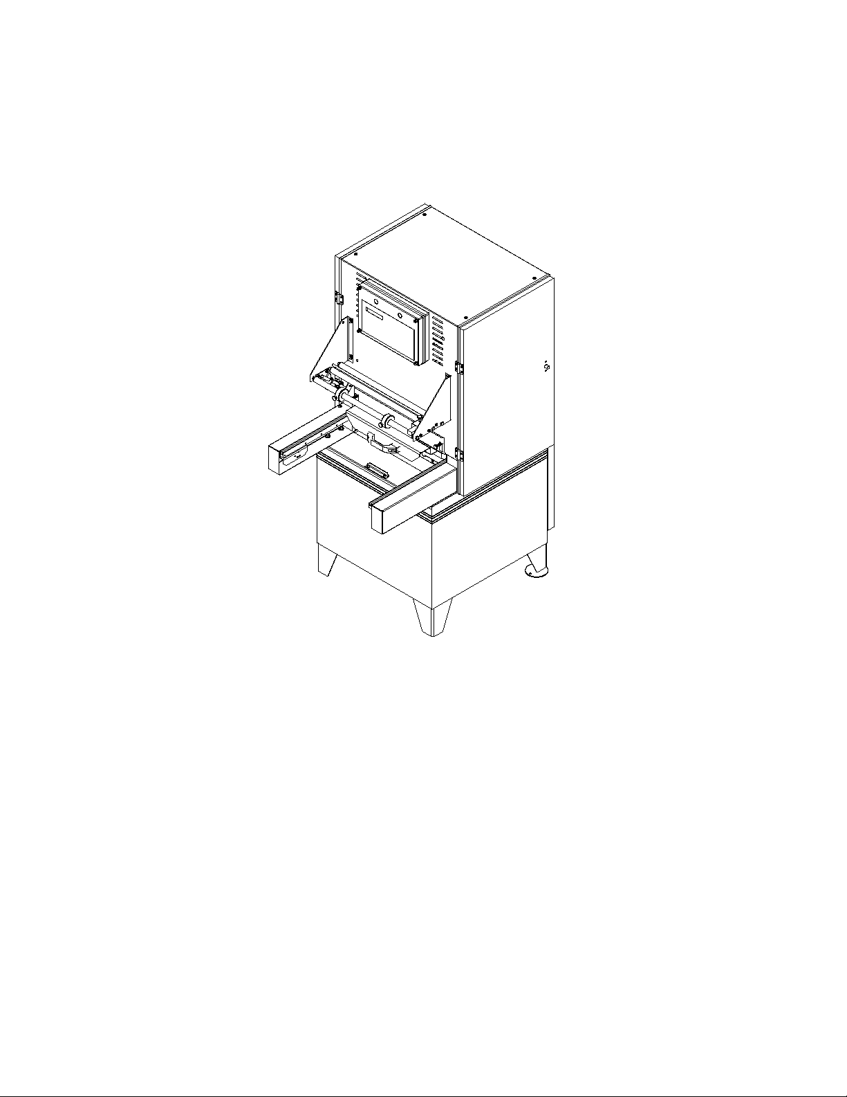
2.1.1. General description
The TS-30, Sipromac vacuum tray sealer has been designed to package a
wide variety of fresh, frozen or processed product that will be sold in a
clean, safe, appe al in g "ca se re ady" container. S ip r om ac tray seali n g M. A.P
(modified-atmosphere-packaging) machines will provide a controlled
oxygen level ensuring freshness for a longer period of time.
The simplified operation sequence is: first the operat or sets the tray on the
bottom chamber. Next, the operator push the drawer under the cover (the
upper chamber) and the optional film rewinder is automatically activated.
When the drawer re achs the correct position, the chamber is push against
the cover and the vacuum is made inside the chamber, followed by
injection of the neutral gas. Then the tray is pushed against an electric
element equipped with a knife to cut off and seal the film. Afterwards, the
chamber will open. The operator pulls back the drawer and take out the
tray and the excess film if the TS-30 is not equipped with a film rewinder.
2.1.2. Sealing Station
2.1.2.1. Chamber
2.1.2.2. Film rewinder
The chamber is divided in 2 parts: the upper chamber and the lower
chamber. A lid gasket allows for a vacuum in the chamber when
both parts come together. It is the lower chamber part that joins the
upper one by the mouvement of the cylinder. Then comes the
vacuum phase in the chamber and the addition of a substitute gas
until atmospheric pressure is reached.
All the tooling is located inside the chamber: the die plate is
located in the lower section and the knifes and heating elements
used to seal the film are in the upper section. The upper cylinder
pressures the h eating element in a way to seal the film on the tray.
A number of spring loaded film support keep the film tight by
maintaining a light pressure during the complete cycle.
A brake-motor leads the rewinder to provide the movement of the
film. The distance of film will move is controlled either by photocell indexer that can read the printed part of the film or by a
mecanical wheel made to each specifications of the trays. The
tightening cones prevent film rippling. Adjustement screws control
the pressure on top of the film for better film tension.
Page 9
2-2
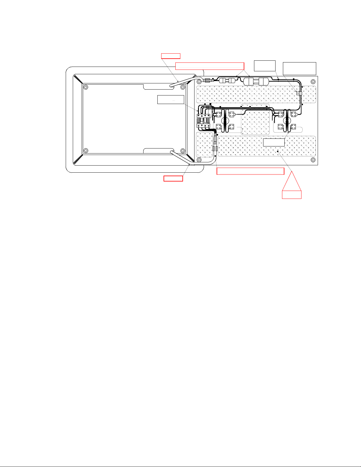
cover
+
-
+
-
Always respect initial wire way
+
-
red
wht
+
-
red
wht
gnd
tooling
red
wht
red
wht
82
82
82
79
79
79
80
80
80
80
80
80
cable ties black
( Tie wrap )
4''
# 057-0305
wire hi temp TEW / 2
AWG
16
# 030-0530
copper tubing
# 105-601
or 105-600
(according movement piece)
Always respect initial wire way
W 003
!
area parts in
movement
loop obligatory
for go & comes
movement
Z5
82 ( Z6)
80 ( Com)
79 ( Z5)
gnd
Z6
Z6
Z5
W 5 & 6
2.2. Tooling insertion
Here is the procedure to change a tooling or remove it for maintenance: (See
Section 8)-Tooling Insertion Check List to make sure all the steps are respected.
2.2.1. Chamber setup
Each tooling contains 2 sub-assemblies:
-the die plate witch is located in the lower chamber,
-the upper tooling witch is located in the upper chamber.
2.2.1.1. Die Plate installation
Take out all the hex socket head bolts (4) using "allen key ¼"
provided with tooling. Remove the die plate from the chamber.
Inverse these steps to put the tooling back. Die plates are d esigned
to avoid installation on the wrong side.
Page 10

2-3
2.2.1.2. Upper tooling insertion
2.2.2. Setup
2.3. Film insertion
The film must follow the path as shown in section 5. Using the m anual feeding
button make the rewinder turn until film 's lock faces up the tube. Make the film
pass over the roll and fix the lock on it. To fix the lock properly make the
rewinder turn one rotation using manual feeding button. The tightening cones
must be located in a way to stretch the film. Locate those on the edge of the film
cutout. Two wheels allow the centering of the roll with the chamber. An
ajustable roller and two handles keep the film tight and smooth on the roll even
when it is almost empty. Look carefull y at section 5 and follow the instructions
regarding the circuit of the film to have the glue on the film toward the tray.
Also, the film must be inside the eye indexer. To remove the used spool roll from
the rewinder, use the special flat tool and pull gently on the lock, then, turn it t o
loosen the film and take the spool out.
Unscrew the nuts (4) of the upper tooling with Allen key 3/16.
Rotate the tooling to the right like opening a door.
Disconnect the 3 connectors.
Inverse the previous steps to put upper tooling back. Make sure all
wires are in their respective connector.The upper tooling has the
same design particularities as the die plate to insure the installation
in the proper position. Put the film back
(See section 2.3)
If there's a ch ange i n the tray model, you may change the encoder wheel if
it is necessary, in cases where die plate had been changed.
Page 11

2-4
2.4. Digital control setting
2.4.1. Basic
Model TS-30 programming is made by the keyboard of the MC
programmable controller. There are 2 modes available on the MC-40:
Program Mode & Function Mode. The MC-40 can store up to 20 programs
with different parameters corresponding to various conditions of use. The
program Mode allows changing in t he current program and also changing
the parameters related to that program. The function Mode set the
parameters of the TS-30 and is valid for all the programs
Use "Power" key to power ON/OFF the vacuum tray sealer. When the unit
is on, the identification of the last executed program is displayed on the
LCD screen.
Use the "ESC" key to change from the program menu to the function menu
and from the fonction menu to the program menu.
In function menu, use "S ELECT" key to select a function and "ENTER"
key to accede and modify the selection.
In program menu, use "S ELECT" key to select a pro gram and "ENTER"
key to accede and modify the selection.
In programs submenu, use "ENTER" key to pass over the parameters and
go to the followin g one; the parameters blink t o point out the acquisition
mode. A return to program menu is performed aut omatically following the
last parameter acquisition.
In program submenu, use "ESC" key to get back to the program menu.
Strike any k ey to clear the error message which may be displayed on the
LCD screen.
There is a emergency stop button on your MC-40 keyboard used for
emergency power cut off.
Password on request ( contact your dealer )
2.4.2. Function menu
Page 12

2-5
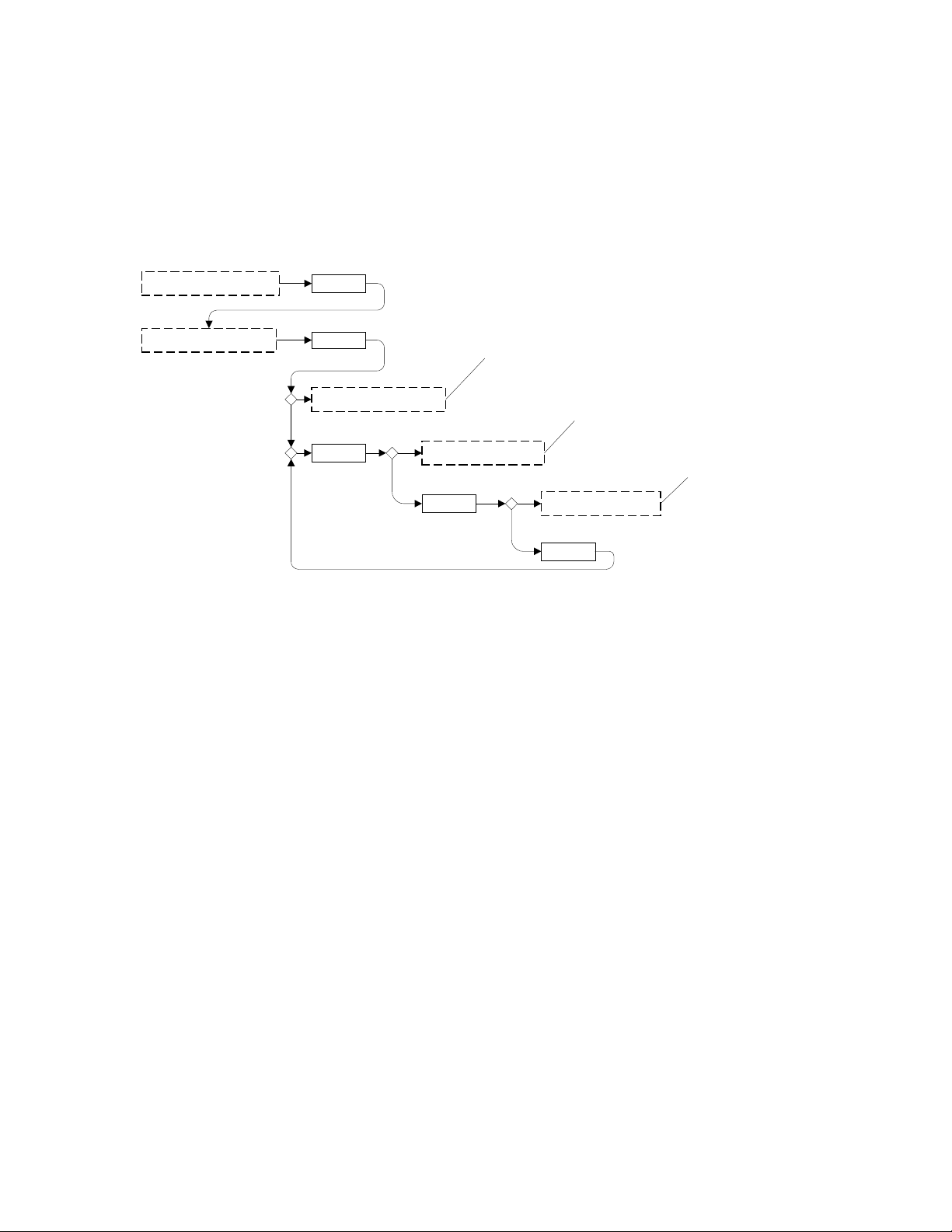
2.4.2.1. F1- Create a program
SELECT Pxx+1 NO NAME
Pxx+2 NO NAMESELECT
SELECT Pxx+... NO NA ME
SELECT
*you may select the
program that you
had created only.
To select a program creat ed
ESC
F1 CREATE A PROGRAM
SELECT
F2 DELETE A PROGRAM
F3 REWIND OPT IO N
SELECT
ESC
Press enter to create
a program
1
-acces this function with enter
2
-
choose the program with select
3
-confirm delete with enter
choose with select
.
rewind enable
.
rewind desable
To create a program and rewind option
F4 REWIND INPUT
SELECT
choose with select
.
encoder
.
photocell
To modify a program created
ON/OFF
VACUUM:xx.x %
Pxx NO NAME
VACUUM PLUS:xx S
SEAL TIME: xx S
ENTER
Enter a value
Enter a value
The program name flash,
you may create a name
for Pxx.
Displayed if gas flush is
enable, see diagnostic
menu. Enter a value.
ENTER
ENTER
ENTER
ENTER
ENTER
GAZ PLUS: x.x S
When executing the "create a program" function, the program
submenu is acceded, starting with the identification. The initial
identification "Pxx NO NAME" is given to the program and all
parameters are established to zero; the program number is allocated
automatically.
For a selected program, set the identification, using the numeric
keyboard characte rs chart; pressing numeric key until the character
you wish is selected (4 times for the numeric value). Use
"ENTER" key to validate the character and to validate the
characters strin g at the end (the new char acters string is blinki ng).
In a middle of an acquisition, use "ESC" key to come backwards
and erase one or several characters.
Page 13

2-6
Example:
key ENTER to validate the characters string
EXAMPLE 1 (9 characters)
keys 2, 2, ENTER -> E
keys 8, 8, 8, ENTER -> X
keys 1, ENTER -> A
keys 5, ENTER -> M
keys 6, ENTER -> P
keys 4, 4, 4, ENTER -> L
keys 2, 2, ENTER -> E
keys 9, 9, 9, ENTER -> space
keys 1, 1, 1, 1, ENTER -> 1
After you entered the program's name, you may enter different
parameters speci fic to the program. You will find the meaning of
the parameters in section 2.4.3.
2.4.2.2. F2- Delete a program
When executing the "delete a program" function, the programs
menu is acceded and the number of the first program in memory
blink to point out the deletion mode. Use "SELECT" key to select a
program and "ENTER" key to accede and confirm deletion of the
selection. Use "ES C" key to unconfirm a deletion and to leave the
function. When leaving the function, the number of the actual
program on the LCD screen will cease to blink.
2.4.2.3. F3 -Rewind Option
This is an option on your Tray Sealer , it has to be enabled if you
have the automatic rewinder.
Page 14

2-7
2.4.2.4. F4- Rewind input
Example:
It's possible to change the input which controls the film's
rewinding. The two possibilities are: ENCODER or PHOTOCELL
choosen by “SELECT” key and “ENTER” key.
When you s elect ENCODER, the film's unwinding will stop when
the flat of the wheel faces the sensor.
If PHOTOCELL is elected you should see a black mark on the film
(±10mm2). This mark tells you where the film's unwinding stops.
2.4.3. Program menu
You can switch from Function Mode to Program Mode by using the E SC
key. You press SELECT key to see all the different programs. It is also
possible to modify the parameters of a program in MODE PROGRAM by
picking up the program you wish with “ENTER” key. Here are the
different parameters regarding each program.
2.4.3.1. Name
Set the program identification by using the numeric keyboard chart,
until the desired caracter is reach then press enter for the next
selection until the complete name is displayed.
2.4.3.2. Vacuum (0 - 99.5%)
Percentage of vacuum to reach i n t he cham ber con sidering "99.5%"
of vacuum almost total. To save cycle time, always use the
minimum vacuum necessary to obtain the correct oxygen level in
the tray.
For a selected program set the vacuum level, starting with the
values; the decimal point is automatically inserted following the
second digit entry and the validation is automatically performed
keys 9, 0, 0 or 9, 0, ENTER or 9, 0, 1 or
keys 9, 0, 2 or 9, 0, 3 or 9, 0, 4 -> 90.0 %
keys 9, 7, 5 or 9, 7, 6 or 9, 7, 7
keys 9, 7, 8 or 9, 7, 9 -> 97.5 %
keys 0, 0, 0 or 0,ENTER -> 0.0 %
Page 15

2-8
following the third digit entry (The new vacuum level blink). The
Example:
keys 1, 5
15 secs
vacuum level is truncated to the nearest lower half value. In the
middle of an acquisition, use "ENTER" key to validate the vacuum
level and "ESC" key to come backward and start over with a new
acquisition (the old vacuum level blink). Set the vacuum level to
zero to bypass the pressure transducer and proceed only using the
vacuum plus time.
2.4.3.3. Vacuum plus (0 – 99 secs)
This value means the time that vacuum will be maintained in the
chamber when we reach the instructions programmed in Vacuum.
During this delay the pump is still vacuuming.
For a selected program set the vacuum plus time, in seconds; the
validation is automatically performed following the second digit
entry (the new vacuum plus time blink). In a middle of an
acquisition, use "ENTER" key to validate the vacuum plus time
and "ESC" key to come backward and start over with a new
acquisition (the old vacuum plus time blink).
keys 0, 1 or 1, ENTER
-> 1 sec
->
2.4.3.4. Gas plus (0.0-5.0 sec)
Value of time for positive pressure of the neutral gas in the
chamber before sealing. It’s an extra pressure regarding to
atmospheric pressure.
If the film appears to bulge out on the top of the sealed tray you
must reduce the value of the Gas Plus. If the opp osite happens and
the film bulges in, increase the value of the Gas Plus.
2.4.3.5. Seal time (0 – 99 secs)
Running time value for the trays to be in contact with the h eating
element. Depend on film and tray material.
For a selected program set the sealing time, starting with the
seconds. Use "ENTER" key to validate the sealing time and "ESC"
key to come backward and start over with a new acquisition (the
old sealing time blink).
Page 16

2-9
Example:
keys 0, 1 or 1, ENTER -> 1 sec
2.4.3.6. Plate temperature (0 – 160 °C)
Heating element temperature. Depend on film and tray material.
N.B: the machine shuts off by itself if the temperature goes higher
than 175 °C.
2.4.4. Operation sequence
Here is a description of a complete sequence to illustrate the function of
each parameter.
2.4.4.1. Vacuum cycle
As soon as the switch indicates the chamber is below the cover,
the cylinder is operated and at the same time the vacuum valve
opens if there is any value other than 0% programmed in
VACUUM. The screen will let you know th e state of the vacuum
evolution. When we get the programmed value in VACUUM, the
cycle goes automatically to VACUUM PLUS cycle which
maintains the valve opened for the delay programmed. The vacuum
valve shuts automatically at the end of the cycle. The gas c ycle c an
now start.
2.4.4.2. Gas cycle
Gas valve opens automatically to reach an over pressure of gas in
the chamber corresponding to the time of GAS PLUS. Gas valve
then shuts and a d elay of 1 second allows time for stabilization in
the chamber before the sealing.
2.4.4.3. Seal cycle
Valve for the bellows is operating during the delay programmed in
SEAL TIME. Sealing is now completed. There is a .5 second delay
before going back at the atmospheric pressure. The atmosphere
control valve operates fo r a minimum of 1 sec and if the vacuum is
below 1% the chamber lock i s released and then the lower chamber
will go down.
Page 17
2-10
2.4.5. System monitor
DIAGNOSTIC MENU
SELECT
SYSTEM MONITOR
ENTER
SOFTWARE: XX.XX
WORK HRS: 00000
CYCLE: 0000000
SELECT
SELECT
SELECT
Shows the total number of
hours done by the machine.
Shows the total number
of cycles done by the
machine
Shows the MC-40
software version.
To access the system monitor, power up the vacuum packaging machine
while keeping the "ESC" key pushed. Use "SELECT" key to select the
system monitor function and "ENTER" key to access and visualize the
monitored parameters. Use "SELECT" key to change over from the software
revision, the amount of working hours done and the amount of complete
cycles performed since first initialization.
A password can be added. For this, please contact your supplier.
Page 18

3-1
3. Trouble shooting
3.1. Failure during a packaging cycle
3.1.1. "VACUUM ERROR" message is displayed on LCD
No pressure variation is picked up by the PCB transducer during the
vacuum sequence within a preset period of time.
-> Check vacuum lines for potential leaks or kinks.
3.1.2. "GAS FLUSH ERROR" message is displayed on LCD
No pressure variation is picked up by the PCB transducer during the gas
sequence within a preset period of time.
-> Check gas flush and vacuum lines for potential leaks or kinks.
3.1.3. "CHAMBER ATM ERROR" message is displayed on LCD
No pressure variation is picked up by the PCB transducer during the
atmosphere sequence within a preset period of time.
-> Check vacuum lines for potential leaks or kicks.
3.1.4. "COVER DOWN ERROR"
The cover switch is defective or needs adjustment , it will happen during
the vacuum cycle if that switch lost the signal .
3.1.5. "HI LIMIT TEMP"
The machine will shut-off by itself if the temperature goes higher than
175°C
In case of failure in triac element or MC-40 board.
Page 19

3-2
3.2. Insufficient vacuum in chamber
To find the leakage quickly, check for leaks with a precision vacuum meter,
going back step by step from the chamber to the pump.
Warning: Verify connections of measuring equipment before verifying machine.
Most frequent points of leakage: lid gasket, damaged vacuum hose or loose hose
clamps.
3.3. Faulty seal
3.3.1. Insufficient seal
-> Sealing pressure too low, bellows leaking or pressure bar jammed.
-> Silicone rubber uneven.
3.3.2. No seal
-> Faulty contact in sealing circuit or bad heating element.
-> Contactor does not work.
3.3.3. Seal does not stick
-> Seal area extremely contaminated by fat or meat juice.
-> Sealing temperature is too low.
Warning: Do not incr ease sealing ti me more than really necessa ry; higher
temperature will reduce working life of Teflon and silicone rubber.
Page 20

3-3
3.3.4. Fault in the valve
Vacuum or air valve does not open.
-> Check whether there is voltage on the magnetic valves during their
period of operation. If there is no voltage a wire is broken or the PC board
is damaged.
Vacuum valve does not close.
Lid does not open at the end of the cycle; air enters, but th ere is still 20 40% vacuum in chamber.
3.4. Control board failure
The board software allows access to a "Diagnostics Menu". Only qualified
service technicians are authorized to access this menu by entering a security
password.
By access either the "D1 input test" feature or the "D2 output test" feature, a
trained technician will be able to quickly know the origin of the problem: pump,
sealing system, pneumatic problem, security switch problem, etc..
Keep in mind that in most cases trouble is due to a leakage, loose electrical
connection or evident damage to the main component: vacuum pump, valves,
electrical contactors, thermal overload, fuses holder or transformer.
For assistance do not hesitate to contact your local service technicians.
Page 21

4-1
4. Maintenance
4.1. Regular maintenance
Routine controls to be made at regular intervals:
Check lid sealing for damage and hardened spots.
Check evacuation hose for damage (contraction of diameter or abrasions).
Check vacuum connections for tightness.
Check oil in pump (oil level in view glass; add if necessary. If the pump oil
changed color, replace it.)
Check vacuum in chamber with precision vacuumeter.
Check the dryer filter if crystal is not blue change the part.
Page 22

4-2
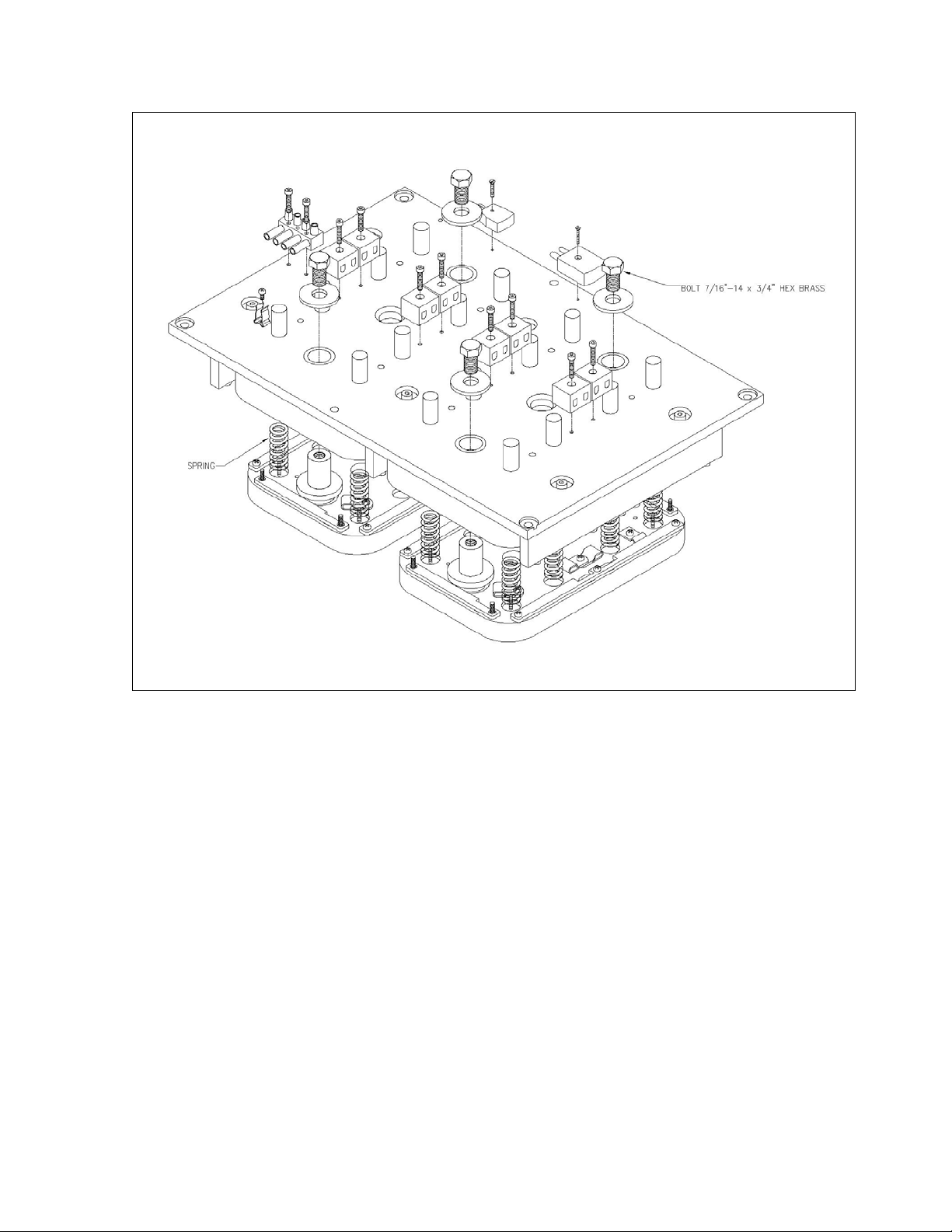
4.2. Heating element replacement
-> Take apart the upper tooling (see section 2.2.1.)
-> Locate where the springs are located. (See Picture 4.1) . Each tooling has it’s
particular configuration, drawing in this manual are only there for example.
Unscrew the bolts (7/16"-14 or ¼”-20) that hold the defective heating plate.
-> Locate the defect heating element with a multimeter (resistivity = 0) than unplug
the heating element.
-> Remove the defect element and replace it by a new one, use special ceramic putty
and high temp red silicon to set the element on the heating plate as was used by
Sipromac.
Some tooling does not require ceramic putty.
-> Reassemble the heating plate.
Page 23
4-3
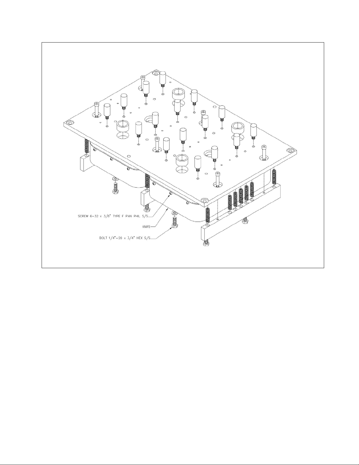
4.3. Blade replacem ent
-> Take apart the heating plate (see section 4.2).
-> Unscrew bolts (1/4"-20 x 3/4") that hold the lower tool plate and take it apart. (see
Picture 4.2)
-> Unscrew screws (6-32 x 3/8") that hold the knife and change the knife.
-> Reassemble the lower tool plate.
4.1 - Heating element replacement
Page 24
4-4
Picture 4.2 - Blade replacement
Page 25

8-1
8. Tooling insertion check list
- Upper tooling insertion
- Film insertion and adjustment
- Mechanical indexer change
- Load appropriate program
Page 26

9-1
9. TS-30 Technical data
9.1. Power consuption
Electric spec.: 208-220V / 3 ph / 60Hz
Vacuum pump BUSCH 40 m3/h, 208-220V / 3 ph / 60Hz
BUSCH 63 m3/h, 208-220V / 3 ph / 60Hz
Power consumption:
Electricity (208-220V / 3 ph / 60Hz) to be confirmed
:
TS-30 without Vacuum pump : approx. 4.6 kW
With vacuum pump BUSH 40 m3/h: approx. 6.1 kW
With vacuum pump BUSH 63 m3/h: approx. 6.8 kW
Disconnect switch require and not supply
Pressurized air:
1/4`` FNPT
Consumption: 1.5 CFM @ 100 PSI
Gaz:
1/2`` FNPT
Minimum recommended supply flow capacity: 45 SCFM
Page 27

9-2
Page 28
19
MECHANICAL DRAWING
Page 29

Page 30
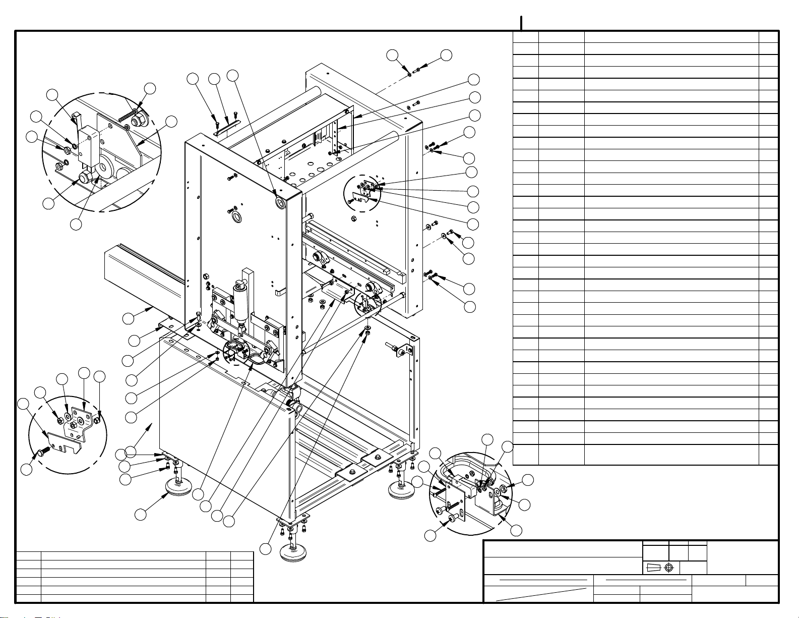
20
22
23
7
12
13
4
DETAIL C
J
H
G
F
E
LET.
DETAIL A
21
19
5
2
9
11
6
7
8
6
7
1
34
32
31
35
ADJUSTABLE FOOT ADDED
026-0692 ETAIT 003-0129
003-0129 ÉTAIT 026-0691
179-0022 ÉTAIT 179-0014 #17
REDESSINÉ
MODIFICATION
005B0646
ITEM PART # DESCRIPTION QT.
6
4
16
3
15
14
29
18
12
4
6
C
7
11
12
13
31
32
4
6
A
B
22
20
25
21
17
30
33
13-08-13
09-06-16
09-05-25
08-12-24
06-07-05
DATE
8
SBU
D.A
J.G.
J.G.
J.G.
INT.
10
.
DETAIL B
28
MACHINE
PART
ITEM
MAT.
1 004B1031 STRUCTURE ASSEMBLY 1
2 001-2131 STRUCTURE TOP 1
3 001-2181 FRONT CHAMBER STOPPER 1
4 051-0190 BOLT 1/4-20 x 3/4" HEX S/S 9
5 004A0501 CHAMBER LIFTING PRE-ASS'Y 1
6 051-0740 WASHER 1/4" FLAT S/S 14
7 051-0581 NUT 1/4"-20 NYLON LOCK S/S 5
8 051-0783 WASHER 3/8" FLAT THICK S/S 20
9 051-0360 BOLT 3/8"-16nc. X 1" S/S 10
10 051-0620 NUT 3/8"-16 NC S/S 10
11 004A0539 COVER LOCK ASSEMBLY 1
12 051-0580 NUT 1/4"-20 S/S 8
13 001A3203 COVER LOCK 1
14 005-0633 ELECTRICAL BOX ASSEMBLY 1
15 051-0210 BOLT ¼"-20nc. X 1" S/S 2
16 036-0260 GROMMET 1-5/16"IDx2"OD RUBBER 5
17 179-0022 PLASTIC EDGE TRIM 3/16'' OFF-WHITE 3
18 001A2170 SWITCH SUPPORT 1
19 051-0757 WASHER 1/4" FLAT THICK S/S 2
20 026-0692 COVER GUARD SWITCH 3
21 051-0086 SCREW 4-40 X 3/4" RND SLOT S/S 6
22 051-0715 WASHER #4 LOCK SS 6
23 051-0540 NUT #4-40 HEX S/S 6
24 001A3820 CHAMBER PINNED SWITCH SUPPORT 2
25 001A3819 CHAMBER PINNED SWITCH FIXATION 2
26 051-0730 WASHER #10 FLAT S/S 4
27 051-0571 NUT #10-24 S/S 4
28 051-0143 SCREW 10-24 x 3/8" PAN PHIL S/S 4
29 004A1711 CONTROLLER SUPPORT PRE-ASSY 1
30 004A0516 CAHMBER STOPPER PRE-ASS'Y 2
31 051-0300 BOLT 5/16"-18 x 3/4" S/S 20
32 051-0762 WASHER 5/16" THICK FLAT S/S 20
33 051-0600 NUT 5/16" -18 S/S 4
34 004A4078 FOOT BASE 4
23
35 003A0397 SWIVEL LEVELING MOUNT SS 3/4"-10 X
6-1/2" RE-WORKED
27
26
24
DEPT. TOL.
METRIC
TS-30
MACHINE ASSEMBLY REAR VIEW
CNC
DWG BY
APP. BY
J.G.
USINAGE
TOLERIE
SOUDAGE
DATE
DATE
06-07-05
INCH
± 0.1
± 0.004"
±
0.5
±
0.020"
±
0.
5
±
0.020"
N.T.S.
DEPT.
NO.
005B0646
ST-GERMAIN DE GRANTHAM
QUEBEC CANADA
M-I
SIPROMAC
QTY.
4
1
Page 31

004B1031
ITEM PART # DESCRIPTION QT.
1 004A0497 STRUCTURE PRE-ASS'Y 1
2 004A1029 PUMP SUPPORT ASSEMBLY 2
3 051-0780 WASHER 3/8" FLAT S/S 4
4 051-0385 BOLT 3/8"-16nc. X 1 3/4" S/S 4
5 005-0088 PUMP SUPP. FIX. PLATE ASS'Y 4
6 004A0571 AIR INLET ASS'Y 1
7 051-0740 WASHER 1/4" FLAT S/S 6
8 051-0180 BOLT. HEX. 1/4"-20 NC. x 1/2" S/S 3
9 051-0580 NUT 1/4"-20 S/S 3
1
10 004B0572 GAS INLET ASS'Y 1
11 005A1324 WATER INLET / OUTLET ASS'Y 1
12 007A0147 RA-40 PUMP INSTALLATION 1
1
A
9
6
7
7
8
DETAIL A
11 SEE NOTEVOIR NOTE
4
3
2
5
10
NOTE:
-POUR OPTION "WATER COOLED" SEULEMENT.
-ONLY FOR WATER COOLED OPTION.
REDESSINÉ S.E. & AJOUTER OPT. WATER COOLED
B
LET.
MODIFICATION
11-12-15
DATE
J.G.
INT.
MACHINE
PART
ITEM
MAT.
TS-30
STRUCTURE ASSEMBLY
CNC
DWG BY
APP. BY
J.G.
DEPT. TOL.
USINAGE
TOLERIE
SOUDAGE
DATE
11-12-15
DATE
METRIC
INCH
± 0.1
± 0.004"
±
0.5
±
0.020"
±
0.
5
±
0.020"
N.T.S.
DEPT.
NO.
004B1031
SIPROMAC
ST-GERMAIN DE GRANTHAM
QUEBEC CANADA
M-I
QTY.
1
Page 32

Page 33

Page 34

Page 35

Page 36

Page 37

Page 38

33
VOIR SK209 POUR CONNECTION.
SEE SK209 FOR CONNECTION.
22
47
48
46
38
50 SEE NOTEVOIR NOTE
21
20
16
49 SEE NOTEVOIR NOTE
VOIR005A0828 POUR CONNECTION (POMPE).
SEE 005A0828 FOR CONNECTION (PUMP).
REDESSINÉ S.E. / AJOUTER OPT. WATER COOLED
J
LET.
MODIFICATION
32
25
26
005B0649
ITEM PART # DESCRIPTION QT.
42 051-0374 BOLT 3/8"-16nc. X 1¼" CAP SKT S/S 2
43 101-0660 STREET ELBOW 90 X 1/4`` NPT BRASS 1
44 114-2020 FILTER / DRYER ¼"mnpt. X 1/4"t.p. COMP. 1
45 101-0036 STRAIGHT ¼"mnpt. X 3/8"t.p. COMP. 1
46 003A0163 ABS BOX DRILLED 1
47 036-0420 PRESSE-ÉTOUPE CD21 1
30
31
29
37
36
48 051-0097 SCREW 6-32 x 3/8" TYPE F PAN PHIL S/S 4
49 101-0170 ELBOW 90° 1/4MNPTx1/4"HOSE 2
50 101-0035 STRAIGHT 1/4"mnpt. X 1/4"t.p. COMP. 2
27
28
24
23
VOIR SK210 POUR CONNECTION.
SEE SK210 FOR CONNECTION.
VOIR005A0828 POUR CONNECTION (POMPE).
SEE 005A0828 FOR CONNECTION (PUMP).
19
17
43
34
1
12
8
6
44
15
13
4
11
9 10
14
45
35
2
40
39
11-12-12
DATE
J.G.
INT.
18
41
42
NOTE:
-OPTION REFROIDIT À L'EAU SEULEMENT.
SI PAS D'OPTION REMPLACER ITEM 50 PAR ITEM 35.
-WATER COOLED OPTION ONLY.
IF NO OPTION REPLACE ITEM 50 BY ITEM 35.
3
MACHINE
PART
ITEM
MAT.
ITEM PART # DESCRIPTION QT.
1 004A0491 COVER PRE-ASSEMBLY 1
2 101-0670 ELBOW STREET 90º 1/2" NPT. BR. 3
3 100-0340 NIPPLE1/2"NPT. X 6" SS 1
4 102-0885 FEMALE COUPLER 3/4" X 1/2"NPTF HOSE
YELLOW
5 102-0885 MALE ADAPTER 3/4" X 1/2" FNPT YELLOW 1
6 101-0218 STRAIGHT ½"mnpt. X ½" HOSE BARB 2
7 104-0104 HOSE 1/2"ID x 3/4"OD PVC BRAIDED 1
8 105-0030 SCREW CLAMPS 3/8" - 7/8" SS/ZC 2
9 101-0390 NIPPLE ½"npt. X 3" BRASS 1
10 101-0620 ELBOW 90° 1/2" FNPT BRASS 1
11 102-0890 MALE ADPATER 3/4" X 1/2" MNPT YELLOW 1
12 104-0105 HOSE 1/2"ID VACUUM POLYWIRE 1
13 004-0762 BUSHING PUSHER PRE-ASS'Y 2
14 051-0162 SCREW 10-24nc. X 5/8" SKT S/S 8
15 077-0200 SPRING C1937-207-3500S COMP. 2
16 002-0684 COVER PLATE PUSHER 1
17 051-0380 BOLT 3/8"-16 x 1-1/2" S/S 8
18 002B1129 COVER PLATE PUSHER ROD 2
19 114-4100 BELLOWS Y1-1B8-562 3/4"npt. 1
20 076-0043 O RING 3/8"Ø id X 5/8"Ø od X 1/8" 4
21 002A1403 BELLOWS STUD 4
22 004A0573 BELLOWS SUPPORT PRE-ASSY 1
7
23 051-0372 BOLT 3/8"-16 x 1-1/4" S/S 4
24 051-0350 BOLT 3/8"-16 NC x 3/4" S/S 2
8
25 101-0938 RED. BUSH, 3/4"mnpt. X 3/8"fnpt. BRASS 1
26 101-0358 HEX. NIPPLE 3/8"NPT BRASS 1
6
27 114-1040 QUIK EXAUST 3/8"npt. 1
28 114-2008 SILENCIEUX 3/8" NPT 1
5
29 101-0910 RED BUSHING 3/8MNPTx1/4FNPT BR 1
30 101-0310 CLOSE NIPPLE 1/4" NPT BRASS 1
4
31 106-0071 VALVE 3WAY 24V 1/4"NPT(G186) 1
32 101-0058 ELBOW 90° ¼"mnpt. X 3/8"T.P. COMP. 1
33 104-0060 TUBE 3/8"OD x 1/4"ID POLYETHYL. 2
34 101-0920 RED BUSHING 1/2MNPTx1/4FNPT BR 2
2
35 101-1030 HEX. PLUG 1/4" NPT BR 1
36 101-0930 RED. BUSHING ½"mnpt. X 3/8"fnpt. BRASS 1
37 036-0327 WIRE CONNECTOR 3/8"npt. 4 HOLES 1
38 036-0326 WIRE CONNECTOR ½"npt. 4 HOLES 1
39 002-0604 COVER PIVOT PIN 2
40 008-0511 COVER SEAL 1
41 004-0660 COVER PLATE ASS'Y 1
DEPT. TOL.
METRIC
TS-30
COVER ASSEMBLY
CNC
DWG BY
APP. BY
J.G.
USINAGE
TOLERIE
SOUDAGE
DATE
DATE
11-12-12
INCH
± 0.1
± 0.004"
±
0.5
±
0.020"
±
0.
5
±
0.020"
N.T.S.
DEPT.
NO.
005B0649
SIPROMAC
ST-GERMAIN DE GRANTHAM
QUEBEC CANADA
M-(I)
QTY.
2
1
Page 39

Page 40

Page 41

Page 42

Page 43

Page 44

Page 45

Page 46

Page 47

004-0762
ITEM PART # DESCRIPTION QT.
1 002-0670 BUSHING PUSHER 1
2
1
2 076-1320 SEAL CUP 1 1/8" X 3/4" X 3/16" 3
3 076-0140 O-RING 1¼" X 1 3/8" X 1/16" 1
4 081-0104 GREASE FITTING 90° x ¼"-28nf. S/S 1
D
C
B
LET.
ADDED TS-70-3S
INVERSER #3 LE PLUS BAS ML
REDESSINER S.E.
MODIFICATION
4
11-02-15
11-02-15
02-04-08
DATE
D.A.
D.A.
D.G.
INT.
3
MACHINE
TS-30, TS-70 & TS-70-3S
PART
BUSHING PUSHER PRE-ASS'Y
ITEM
MAT.
CNC
DWG BY
APP. BY
DENIS
DEPT. TOL.
USINAGE
TOLERIE
SOUDAGE
DATE
02-04-08
DATE
METRIC
INCH
± 0.1
± 0.004"
±
0.5
±
0.020"
±
0.
5
±
0.020"
N.T.S.
DEPT.
NO.
004-0762
SIPROMAC
ST-GERMAIN DE GRANTHAM
QUEBEC CANADA
M
QTY.
2
Page 48

Page 49

LAISSER DÉPASSER LE "SET SCREW" DE 13mm DE LA COVER PLATE
3
2
004-0660
ITEM PART # DESCRIPTION QT.
1 0020658 COVER PLATE 1
2 0510217 SET SCREW ¼"20nc. X 1" S/S 4
3 0020587 TOOL PLATE SPACER 4
REDESSINÉ S.E. & VUE 002-0658 & NOTE
C
LET.
MODIFICATION
02-05-15
DATE
J.G.
INT.
MACHINE
PART
ITEM
MAT.
TS-70 & TS-30
COVER PLATE ASS'Y
CNC
DWG BY
APP. BY
DENIS
DEPT. TOL.
USINAGE
TOLERIE
SOUDAGE
DATE
02-05-15
DATE
METRIC
INCH
± 0.1
± 0.004"
±
0.5
±
0.020"
±
0.
5
±
0.020"
N.T.S.
DEPT.
NO.
004-0660
SIPROMAC
ST-GERMAIN DE GRANTHAM
QUEBEC CANADA
M
QTY.
1
Page 50

Page 51

Page 52

1
VOIR NOTE
SEE NOTE
VOIR NOTE
SEE NOTE
NOTE:
-ENLEVER ITEMS 13 @ 19 DE GAUCHE POUR OPTION "NO REWINDER".
-REMOVE LEFT ITEMS 13 @ 19 FOR OPTION NO REWINDER.
5
19
3
2
004A0537
ITEM PART # DESCRIPTION QT.
1 001A2139 FILM SUPPORT 2
2 051-0780 WASHER 3/8" FLAT S/S 8
3 051-0350 BOLT 3/8"-16 NC x 3/4" S/S 4
4 051-0620 NUT 3/8"-16 NC S/S 10
5 002A1159 FILM SUPPORT REINF. 1
6 051-0190 BOLT 1/4-20 x 3/4" HEX S/S 2
7 008-0501 FILM SUPPORT ROLLER 3
8 002-0569 FILM POSITIONER 2
9 051-0220 SCREW ¼"-20nc x 1" SKT. CAP S/S 2
10 057-0004 THMB SCREW KNOB 1/4" 2
11 075-2000 NYLON BEARING 7/8" W/ S/S BALLS 6
12 003-0092 ROLLER AXLE 6
13 004-0498 FILM SUPPORT BREAK HOLDER PRE-ASS'Y 2
14 051-0185 SCREW 1/4-20x 1/2"PAN PHIL S/S 4
15 051-0580 NUT 1/4"-20 S/S 4
16 002A0605 FILM SUPPORT BREAK 2
17 077-0095 SPRING C 0360-059-1250 S/S 2
18 051-0581 NUT 1/4"-20 NYLON LOCK S/S 2
19 004A3824 BREAK ADJ. SCREW 2
10
CHANGER QTÉE ITEM 13 @ 19 SELON OPTION
F
MODIF. #A-0446 077-0095 ÉTAIT 077-0080
E
D
LET.
REDESSINÉ
MODIFICATION
6
2
4
14
MACHINE
12
PART
TS-30
FILM SUPPORT ASSEMBLY
ITEM
MAT.
CNC
DWG BY
APP. BY
J.G.
J.G.
J.G.
INT.
16
17
15
11
2
3
4
13
18
7
89
11-12-14
09-08-24
07-05-07
DATE
J.G.
DEPT. TOL.
USINAGE
TOLERIE
SOUDAGE
DATE
07-05-07
DATE
METRIC
INCH
± 0.1
± 0.004"
±
0.5
±
0.020"
±
0.
5
±
0.020"
N.T.S.
DEPT.
NO.
004A0537
SIPROMAC
ST-GERMAIN DE GRANTHAM
QUEBEC CANADA
M-I
QTY.
1
Page 53

Page 54

Page 55

Page 56

Page 57

Page 58

Page 59

28
19
18
005-0629
36
5
36
5
13
14
37
9
11
10
DETAIL A
11
12
ITEM PART # DESCRIPTION QT.
23 004-0709 REWINDER HOUSING PRE-ASS'Y 1
24 051-0740 WASHER 1/4" FLAT S/S 12
25 051-0255 BOLT 1/4-20 x 1-3/4" HEX SS 4
26 051-0580 NUT 1/4"-20 S/S 8
27 002-0671 FILM ROLLER 1
28 004-0669 FILM HOLDER PRE-ASS'Y 1
29 001A2577 FILM HOLDER RETAINER 1
30 051-0097 SCREW 6-32 x 3/8" TYPE F PAN PHIL S/S 2
31 008-0582 GEARBOX / SHAFT KEY 1
32 004A1226 REWINDER GEARBOX ASSEMBLY 1
33 051-0189 BOLT 1/4-20 x 5/8" HEX S/S 4
34 051-0757 WASHER 1/4" FLAT THICK S/S 1
35 051-0210 BOLT ¼"-20nc. X 1" S/S 1
36 051-0622 NUT 3/8"-16nc. NYLON LOCK S/S 4
37 008-0522 TENSION ROD 1
38 001A2223 GEARBOX ARM 1
39 001A2760 GUIDE ROLLER EXTENSION 2
40 051-0360 BOLT 3/8"-16nc. X 1" S/S 2
27
30
29
25
23
24
21
26
33
2424
ITEM PART # DESCRIPTION QT.
1 004A0670 ROLLER SUPPORT PRE-ASS'Y 1
2 002-0673 REWINDER HINGE 1
3 002-0677 HINGE SHAFT 1
4 056-0331 EXT. RETAINING RING 1/2" S/S 2
5 051-0780 WASHER 3/8" FLAT S/S 16
6 051-0400 BOLT 3/8"-16 NC X 2 1/4" S/S 2
7 051-0620 NUT 3/8"-16 NC S/S 12
8 008A0526 REAR FILM GUIDE ROLLER 1
9 075-2000 NYLON BEARING 7/8" W/ S/S BALLS 2
10 051-0621 HALF-NUT 3/8"-16 SS 2
11 051-0783 WASHER 3/8" FLAT THICK S/S 10
12 003-0092 ROLLER AXLE 2
13 002-0858 REWINDER CONE 2
14 051-0178 SCREW 1/4"-20 x 5/16" SKT SET S/S 2
15 001-2222 ADJUSTABLE LOCK PLATE 1
16 051-0350 BOLT 3/8"-16 NC x 3/4" S/S 6
17 002-0672 ADJUSTABLE LOCK 1
18 051-0196 BOLT 1/4"-20 x 3/4" CAP HEX SKT.S/S 1
19 057-0004 THMB SCREW KNOB 1/4" 1
20 001-2228 ROLLER PLATE SUPPORT 1
38
21 002-0676 ROLLER PLATE 1
22 051-0410 BOLT 3/8"-nc. X 2.75" S/S 4
31
26
7 VOIR NOTE
39 VOIR NOTE
17
7
11
15
11
16
NOTE:
-INSTALLER ITEM #39 AU BESOIN
SELON TOOLING ET LE SENSE
AVANT/ ARRIÈRE AU BESOIN.
#13 002-0858 PLUS GROS EN DIAMÈTRE
J
H
LET.
REDESSINÉ
MODIFICATION
40
7
5
2
6
35
09-01-14
07-05-07
DATE
J.G.
J.G.
INT.
34
20
MACHINE
A
3
1
4
8
37
13
5
16 VOIR NOTE
39 VOIR NOTE36
12
11
PART
ITEM
MAT.
22
5
TS-30
REWINDER ASSEMBLY
32
-OPTION REWINDER-
DEPT. TOL.
METRIC
USINAGE
± 0.1
TOLERIE
±
0.5
±
0.
07-05-07
5
CNC
DWG BY
APP. BY
J.G.
SOUDAGE
DATE
DATE
INCH
± 0.004"
SIPROMAC
±
0.020"
±
0.020"
ST-GERMAIN DE GRANTHAM
QUEBEC CANADA
N.T.S.
DEPT.
M-I
NO.
005-0629
QTY.
1
Page 60

010-0041
ITEM PART # DESCRIPTION QT.
1 001-2254 AIR SWITCH SUPPORT 1
2 051-0540 NUT #4-40 HEX S/S 1
3 051-0713 WASHER #4 FLAT S/S 1
4 051-0086 SCREW 4-40 X 3/4" RND SLOT S/S 1
5 004-0830 FILM GUIDE PRE-ASSEMBLY 1
6 077-0100 SPRING C 0390-047-1000 S COMP. 1
7 051-0261 SCREW ¼"-20nc X 2" CAP HEX SKT S/S 1
8 057-0004 THMB SCREW KNOB 1/4" 1
5
6
7
8
2
3
1 UTILISER LES BOULONS EXISTANTS POUR INSTALLER / USE EXISTING BOLTS TO INSTALL.
REDESSINÉ S.E. 026-0691 ÉTAIT 026-0690
A
LET.
MODIFICATION
4
0260691
LIQUID TIGHT LIMIT SWITCH
11-12-12
J.G.
DATE
INT.
-REWINDER OPTION -
MACHINE
TS-30
PART
REWINDER SWITCH INST.
ITEM
MAT.
CNC
DWG BY
APP. BY
J.G.
DEPT. TOL.
USINAGE
TOLERIE
SOUDAGE
DATE
11-12-15
DATE
METRIC
INCH
± 0.1
± 0.004"
±
0.5
±
0.020"
±
0.
5
±
0.020"
N.T.S.
DEPT.
NO.
010-0041
SIPROMAC
ST-GERMAIN DE GRANTHAM
QUEBEC CANADA
I
QTY.
1
Page 61

Page 62

Page 63

Page 64

1251030 (BUSCH PUMP KB40)
6
5
1060030 (VALVE 2 WAY 24V 3/4"NPT (G95) 60Hz)
IN
005A0828
ITEM PART # DESCRIPTION QT.
1 103-0557 RED BUSHING 1 1/4"NPT X 3/4"NPT ZC 1
2 103-0237 CLOSE NIPPLE 3/4" NPT 3
3 103-0467 T 3/4" NPT ZINC 2
4 103-0527 RED.BUSH.3/4"NPTx1/4"NPT ZINC 1
5 101-0170 ELBOW 90° 1/4MNPTx1/4"HOSE 1
6 059-0015 RUBBER TIP 15/64"SHAFT 1
7 103-0537 RED. BUSH. 3/4"mnpt. X ½"fnpt. ZINC 2
8 103-0232 CLOSE-NIPPLE 1/2" ZINC 2
9 103-0462 T 1/2" NPT ZINC 1
10 103-0077 ELBOW STREET 1/2" NPT ZC 1
11 101-0218 STRAIGHT ½"mnpt. X ½" HOSE BARB 2
12 105-0030 SCREW CLAMPS 3/8" - 7/8" SS/ZC 2
VOIR 005B0649 POUR CONNECTION (CLOCHE)
SEE 005B0649 FOR CONNECTION (COVER)
LET.
1
VOIR 005B0643 POUR CONNECTION (CUVE)
SEE 005B0643 FOR CONNECTION (CHAMBER)
MODIFICATION
2
DATE
3
2
4
7
8
9
1060020 (VALVE 2 WAY 24V 1/2"NPT (G94) 60Hz)
12
11
10
NOTE:
- "BUSH " PUMP B-40 220V/ 1Ph/ 60Hz =125-0034
- "BUSH " PUMP KB-40 240V-460V/ 3Ph / 60Hz =125-1030
-OPTION PAS VALVE DE SECURITE -
INT.
MACHINE
PART
TS-30
PUMP INSTALLATION KB-40
ITEM
MAT.
CNC
DWG BY
APP. BY
Y.C.
DEPT. TOL.
USINAGE
TOLERIE
SOUDAGE
DATE
03-04-07
DATE
METRIC
INCH
± 0.1
± 0.004"
±
0.5
±
0.020"
±
0.
5
±
0.020"
N.T.S.
DEPT.
NO.
005A0828
SIPROMAC
ST-GERMAIN DE GRANTHAM
QUEBEC CANADA
M
QTY.
1
Page 65

004A4177
ITEM PART # DESCRIPTION QT.
1 004A3828 VALVE SUPPORT 1
2 100-0065 STREET ELBOW 1/4" NPT SS 1
3 100-0225 CLOSE NIPPLE 1/4" NPT SS 1
4 102-0390 MALE CONN. ¼"mnpt. X ¼"T. QUICK 2
5 106-0010 VALVE 2WAY 24V 1/4"NPT(G22) 60Hz 1
4
1
7
2
3
6 107-0022 BALL VALVE 1/4'' NPT SS 1
7 114-0144 PRESSURE REGUL.0-25PSI 1/4'' NPT
W/GAUGE
5
1
LET. MODIFICATION
DATE
INT.
-WATER COOLED OPTION -
6
MACHINE
TS-30
PART
WATER VALVE ASSY
ITEM
MAT.
CNC
DWG BY
APP. BY
SBU
DEPT. TOL.
USINAGE
TOLERIE
SOUDAGE
DATE
14-02-06
DATE
METRIC
INCH
± 0.1
± 0.004"
±
0.5
±
0.020"
±
0.
5
±
0.020"
N.T.S.
DEPT.
NO.
004A4177
SIPROMAC
ST-GERMAIN DE GRANTHAM
QUEBEC CANADA
M
QTY.
1
Page 66

20
ELECTRICAL DRAWING
Page 67

FULL FILENAME H:\DESSIN\DEPTDESS\PRODUCTS\510-SIPROSEAL\TS-30\ELECTRIQUE-P NE UMATIQUE\006-2730 TS-30 POWER 1 PAGE.VSD
L2 L3
Gnd
L1
006-2730
Tested at: V / 3 Ph / 60 Hz
PAGE
1 de 1
AMPERAGE
name
plate
mesured
F 1
F 2
Gnd
Body
volt.
circuit
VACUUM PUMP
3
M /h
Model:
Sn :
40 or 63
W17
REWINDER (OPTION)
MOTOR
Model:
Sn :
GEARBOX :
Model :
Sn :
Ratio :
3 Ph / 60 Hz
month
year
06 05 19
PP XXPP
day
drawconcept
app
TOOLING
TOTAL :
block
006-2730
Kw :
SIPROMAC
St-Germain de Grantham
QUEBEC ,CANADA
PAGE
AA
1 de 1
C1 O/L1
C2
red
wht
blk
wht
red
blk
C6
F3
F3
C5
C5
F4
F4
control
circuit
C6
W001
M1
MOTOR REWINDER JUNCTION BOX
manual
scrolling
PBX
impulse
W002
W005
red
blk
wht
category
system
usual
fonctions
options
W003
L1
L2
JB1
CPF1
TRAY SEALERS
Z6
GND
COM
N
Z5
model
POWER
red
gre
brake system
D1
M2
solid state
motor terminals
coupling
TOOLING PLATE #:
TS 30
+
-
wht
blk
Page 68

FULL FILENAME H:\PRODUITS\510-SIPROSEAL\TS-30\ELECTRIQUE-PNEUMATIQUE\006-2737 TS-30 COMMAND 4 PAGE.VSD
MC40
Prog. version :
in out
TS-32e or f
006-2737
PAGE
1 de 4
10
JP4
8
7
9
10
JP3/1
gre / blk
org / blk
red / blk
wht / blk
blk
C1
C3
C11
C12
A1
34
25
25
13
F8
4A
24 Volts
F9
2A
6
9 Volts
233 (blu)
233 ( blu)
TR1
24
From page 1 de 1
9
50 / 60Hz
115VA
E. STOP
4
JP4
9
blu / red
yel
ES1
wht
wht
C10
A3
W8
JP4
34
35 (yel)
223 (blu)
Photocell
(OPTION)
S1
blk
wht
A9
229
A4
-
+
25
R2
OUT AUTOMATON
COMMON INTERN
PC BOARD
W 7
category
system
usual
fonctions
options
TRAY SEALER
model
TS 30
POWER SUPPLY CONTROL CIRCUIT
W16
red
volt.
circuit
A2
ALL
month
year
day
05 09 29
drawconcept
app
PP DLPP
223
block
006-2737
SIPROMAC
St-Germain de Grantham
QUEBEC ,CANADA
PAGE
1 de 4
Page 69

FULL FILENAME H:\PRODUITS\510-SIPROSEAL\TS-30\ELECTRIQUE-PNEUMATIQUE\006-2737 TS-30 COMMAND 4 PAGE.VSD
MC40
in out
24 VAC
W 7
W 8
PS1
AC
006-2737
PAGE
2 de 4
24 VAC
-24 VDC
24 VAC
Before E.STOP
POWER
SUPPLY
2
red
34
3
blk
15 VDC
251
251
RES1
252
249 ohms
250
252
250
254
255
RTD
TT1
TEMP.
SENSOR
Z6
JP6
251
B
RTD
TT2
OL1
96 95
35
TEMP.
SENSOR
Z5
VACUUM
PUMP
HEATING
PLATE
Z6
JP5
red
3
blk
2
Relay
13
8
JP3/2
7
or / red
wht / red
D10
D2
251
RES2
253
249 ohms
TO CPF2
TOOLING
# : ___
95
203
253
L1
N
L2
CPM2
male
W004
256
257
C1
C1
C6
JP3/2
PC
BOARD
11
common intern
5
JP3/2
automaton
blu / wht
D1
202
C5
HEATING
PLATE
Z5
C1
blk
13 14
W20
W 7 cont'd
W 8 cont'd
category
system
usual
fonctions
options
TRAY SEALER
HEATER CONTROL
model
TS 30
volt.
circuit
2 w
V8
year
11 03 23
PP DLPP
wht
ALL
month
drawconcept
day
app
SIPROMAC
block
St-Germain de Grantham
QUEBEC ,CANADA
006-2737
Option
Water
Cool
PAGE
2 de 4
Page 70

FULL FILENAME H:\PRODUITS\510-SIPROSEAL\TS-30\ELECTRIQUE-PNEUMATIQUE\006-2737 TS-30 COMMAND 4 PAGE.VSD
006-2737
PAGE
3 de 4
MC40
version :
TS-32 e
in out
3
JP4
2
JP4
6
JP4
34
5
JP4
PC BOARD
or f
brn
B1
encoder switch
LM1
blk
wht
red
A5
223
-24 VDC
SCROLLING
AUTOMATIC
CONTROL
W20
(OPTION)
rew. motor
pur
A10
224
C2
223
21 22
manual scrolling
(Rewinder option)
impulse
W17
org
B4
red
gre
PBX
TG
motor rewinder
A11
226
W 7 cont'd
W 8 cont'd
COMMON INTERN OUT AUTOMATON
13
14
C2
227
A12
wht
blk
junction box
solid state
brake system
A6
223
25
REWINDER
CONTROL
(OPTION)
rew. start switch
A7
223
blu
B2
W19
blk
LM2
wht
red
fault rewinder
7
8
1
JP3/2
2
JP3/2
blu / blk
blk / wht
MCR
R4
9
R3
240 241 242
5
1
category
system
usual
fonctions
options
D3
D12
222
209
photocellfault rew rewinder
R2
2
109
53
TRAY SEALER
REWINDER CONTROL
C2
54
model
TS 30
209
volt.
circuit
R3
rew.motor
C2
ALL
month
year
05 09 27
PP DLPP
day
drawconcept
app
SIPROMAC
block
St-Germain de Grantham
QUEBEC ,CANADA
006-2737
PAGE
3 de 4
Page 71

FULL FILENAME H:\PRODUITS\510-SIPROSEAL\TS-30\ELECTRIQUE-PNEUMATIQUE\006-2737 TS-30 COMMAND 4 PAGE.VSD
MC40
in out
version :
1
JP4
TS-32 e
or f
gry
B3
W8
W7 cont'd
6
6
blu
D5
JP3/1
chamber position switch
blk
W15
LM3
wht
red
006-2737
A8
C5
223
35 (yel)
PAGE
4 de 4
CHAMBER
POSITION
3
3
red
JP3/1
12
6
blk / red
JP3/2
1
1
blk
JP3/1
2
2
wht
JP3/1
9
3
red / wht
JP3/2
4
4
gre
JP3/1
5
5
org
JP3/1
PC
BOARD
On the LM3 , LM10 & LM11 limit switches, you must change the location
Note:
of the arm of the switch so the roller is outside of the switch. The axe of
the arm shall be on the farthest point, on the opposite side of the tabs.
D6
D11
D7
D8
D9
D4
LM10 LM11
blk
category
system
functions
options
TRAY SEALER
usual
blk
V2
4 w
W13
whtblk wht
W5
W6
blk
V7
2 w
W 11
model
PUMP & E.V. CONTROL
wht
W 10
wht
blk
C2
TS 30
W 12
2 w
V5
blk
W 9
W18
blk
blk
wht
2 w
3 w
3 w
volt.
circuit
V3
V6
V1
C6
C7
wht
C8
C9
wht
wht
C4
ALL
month
year
11 03 23
drawconcept
PP DLPP
day
app
SIPROMAC
block
St-Germain de Grantham
QUEBEC ,CANADA
006-2737
CAM
25
CYLINDER
VACUUM
VALVE
STANDARD
GAS CHAMBER
BELLOW
FILM CUT
ATMOSPHERE
PAGE
4 de 4
Page 72

# PART PART MACHINE
MACHINE
REF. QTY
SIPRO DESCRIPTION APPLICATION VOLTAGE
034-0755 FUSE HOLDER 30A 1 PÔLE PUMP 208V/3PH/60HZ TS-30 F1 3
034-0530 FUSE 20A/250V TD PUMP 208V/3PH/60HZ TS-30 F1 3
025-0025
MOTOR CONTACTOR 3HP IN 208V/3PH
PUMP 208V/3PH/60HZ TS-30 C1 1
025-0170
THERMAL OVERLOAD 7 TO 10A
PUMP 208V/3PH/60HZ TS-30 O/L1 1
030-0140 CAB TIRE PUMP 208V/3PH/60HZ TS-30 W001 2M.
125-0030
BUSCH RA-0040 208V/3/60 3HP CSA 8.4A
PUMP 208V/3PH/60HZ TS-30 M1 1
125-0040 BUSCH RA0063 230-460V/3PH/60HZ PUMP 208V/3PH/60HZ TS-30 M1 1
034-0755 FUSE HOLDER 30A 1 PÔLE REWINDER 208V/3PH/60HZ TS-30 F2 3
034-0500 FUSE 15A/250V TD REWINDER 208V/3PH/60HZ TS-30 F2 3
025-0010 MOTOR CONTACTOR REWINDER 208V/3PH/60HZ TS-30 C2 1
030-0250 CAB TIRE REWINDER 208V/3PH/60HZ TS-30 W002 2M.
037-1232
GEAR/MT: VF 30 30:1 230/460 3PH 60HZ BRAKE
REWINDER 208V/3PH/60HZ TS-30 M2 1
026-0690 LIQUID TIGHT LIMIT SWITCH
ALL TS-30 LM2 1
026-1010 TOGGLE SWITCH ETANCHE REWINDER JOG ALL TS-30 PBX 1
025-0600 4PDT RELAY 24VAC (55.34-24VAC) REW.FAULT ALL TS-30 R3 1
025-0610 4PDT RELAY SOCKET 24VAC REW.FAULT ALL TS-30 R3 1
025-0611 RELAY SOCKET RETAINING CLIP(FINDER) REW.FAULT ALL TS-30 R3 1
034-0755 FUSE HOLDER 30A 1 PÔLE HEATING 208V/3PH/60HZ TS-30 F3 2
034-0540 FUSE 20A/600V FA HEATING 208V/3PH/60HZ TS-30 F3 2
025-0010 MOTOR CONTACTOR HEATING 208V/3PH/60HZ TS-30 C5+C6 2
030-0140 CAB TIRE HEATING 208V/3PH/60HZ TS-30 W003 2M.
003A0163 ABS BOX DRILLED HEATING ALL TS-30 JB1 1
033-1000 POWER SUPPLY 24V 1 AMP. TEMP. READING ALL TS-30 PS1 1
031-0009 TEMPERATURE TRANSMITER TEMP. READING ALL TS-30 TT1+TT2 2
033-0309 RESISTOR 249 OHMS,1/4 W,1%,METAL FILM TEMP. READING ALL TS-30 RES1+RES2 2
031-0008 RTD MINIATURE SENSOR TEMP. READING ALL TS-30 2
034-0740 FUSE HOLDER M4/8SF TRANSFO ALL TS-30 F4-F8-F9 4
034-0205 FUSE 1A/250V TD TRANSFO 208V/3PH/60HZ TS-30 F4 2
029-0010 TRANSFO 115VA 575-400-230-208-190/24-9 TRANSFO 208V/3PH/60HZ TS-30 TR1 1
034-0240 FUSE 4A/250V TD 24VAC ALL TS-30 F8 1
034-0210 FUSE 2A/250V TD 9VAC ALL TS-30 F9 1
033-0015 MEMBRANE MC-40 SIPROMAC CONTROL ALL TS-30 1
033-0042 MICROPROCESSOR MC-40 TS-30 CONTROL ALL TS-30 1
026-0485 EMERGENCY STOP LEGEND E-STOP ALL TS-30 1
026-0150 EMERGENCY BUTTON,(PUSH-PULL) E-STOP ALL TS-30 1
026-0025 1 N.C CONTACT WITH BASE E-STOP ALL TS-30 1
026-0030 1 N.C. CONTACT BLOCK E-STOP ALL TS-30 1
026-0260 BLANKING PLUG ALL TS-30 1
026-0690 LIQUID TIGHT LIMIT SWITCH REW. START ALL TS-30 LM2 1
026-0692 LIQUID TIGHT LIMIT SWITCH BELLOW SECURITY ALL TS-30 LM10+LM11 2
026-0692 LIQUID TIGHT LIMIT SWITCH CHAMB. POS.+ENCODER ALL TS-30 LM2+LM3 2
Page 73

# PART PART MACHINE
MACHINE
REF. QTY
SIPRO DESCRIPTION APPLICATION VOLTAGE
027-0705 MALE COMPACT PLUG CONN.18/4 TOOLING ALL TS-30 CPM1+CPM2 2
027-0706 FEMALE COMPACT PLUG CONN.18/4 TOOLING ALL TS-30 CPF1+CPF2 2
114-0820 VALVE 4WAY 24VAC 1/8 NPT CAM ALL TS-30 V2 1
114-0850 DIN CONNECTOR CAM ALL TS-30 V2 1
106-0020 VALVE 2WAY 24V 1/2 NPT 60Hz VACUUM ALL TS-30 V3 1
106-0030 VALVE 2WAY 24V 3/4 NPT 60Hz GAS ALL TS-30 V5 1
106-0071 VALVE 3 WAY 24V 1/4 NPT (G186) BELLOW ALL TS-30 V6 1
106-0020 VALVE 2WAY 24V 1/2 NPT 60Hz ATMOSPHERE ALL TS-30 V7 1
106-0410 SCREW TERMINAL ADAPTER(ASCO) ALL ASCO VALVE ALL TS-30 V6 1
106-0420 JUNCTION BOX PLASTIC ALL ASCO VALVE ALL TS-30 B6 1
036-3020 SEALED DIN CONNECTOR (3M CABLE) ALL SMC VALVE ALL TS-30 V3, V5, V7 3
028-0140 BARETTE/BORNIER 12VIS 300V/20A. CONTROL ALL TS-30 A-B-C-D 4
Page 74

TS-30
OPERCULEUSE
Manuel du Propriétaire
MACHINE NUMBER:…………………
SIPROMAC
240 BOUL. INDUSTRIEL
ST-GERMAIN DE GRANTHAM
QUEBEC CANADA J0C 1K0
(819) 395-5151
Page 75

OPERCULEUSE
MODÈLE TS-30
TABLE DES MATIÈRES
Section 1- Installation
1.1. Environnement
1.2. Nivelage
1.3. Installation de la Pompe à vide
1.4. Branchements
1.4.1. Branchements électrique
1.4.2. Branchement pneumatique
Section 2- Fonctionnement
2.1. Principe de fonctionnement
2.1.1. Description générale
2.1.2. Station de scellage
2.1.2.1. Chambre
2.1.2.2. Rembobineur de film
Page 76

2.2. Installation de l’outillage
2.2.1. Préparation de la chambre
2.2.1.1. Installation de la plaque matrice
2.2.1.2. Installation de l’outillage supérieur
2.2.2. Préparation
2.3. Installation du film
2.4. Paramétrage du contrôle
2.4.1. Essentiel
2.4.2. Menu Fonction
2.4.2.1. F1- Créer un programme
2.4.2.2. F2- Effacer un programme
2.4.2.3. F3- Option Rembobineur
2.4.2.4. F4- Saisie de Rembobinage
2.4.3. Menu Programme
2.4.3.1. Name
2.4.3.2. Vacuum
2.4.3.3. Vacuum plus
2.4.3.4. Gas plus
2.4.3.5. Seal time
2.4.3.6. Plate temp C
2.4.4. Séquence d’opération
2.4.4.1. Vacuum cycle
2.4.4.2. Gas cycle
2.4.4.3. Seal cycle
2.4.5. System monitor
Page 77

Section 3- Diagnostique des pannes
3.1. Défaillance pendant le cycle d’emballage
3.1.1. "VACUUM ERROR" message affiché sur l’écran
3.1.2. "GAS FLUSH ERROR" message affiché sur l’écran
3.1.3. "CHAMBER ATM ERROR" message affiché sur l’écran
3.1.4. "COVER DOWN ERROR" message affiché sur l’écran
3.1.5. "`HIGH LIMIT TEMP" message affiché sur l’écran
3.2. Vide insuffisant dans la chambre
3.3. Scellage défectueux
3.3.1. Scellage insuffisant
3.3.2. Manque de scellage
3.3.3. Scellage se décolle
3.3.4. Valve défectueuse
3.4. Panneau de contrôle défectueux
Section 4- Entretien
4.1. Entretien régulier
4.2. Changement des éléments chauffant
4.3. Changement des lames
Section 5- Dessins mécanique
Section 6- Dessins électrique
6.1. Assemblage du panneau de contrôle
6.2. Branchement des terminaux de contrôle
6.3. Détail du branchement de la boite électrique
6.4. Branchement de la carte de contrôle
6.5. Schéma de puissance
6.6. Schéma de contrôle
Page 78

6.7. Branchement du couvercle
6.8. Branchement de l’outillage
Section 7- Dessins pneumatique
Section 8- Liste de contrôle d’installation de l’outillage
Section 9- Données techniques TS-30
Page 79

1-1
Section 1- Installation
1.1. Environnement
La machine doit être positionnée pour assurer une accessibilité appropriée pour
l’entretien et l’opération. Choisir un endroit qui procure assez d’espace pour les
produits emballés et non-emballés.
1.2. Nivelage
Pour assurer un bon fonctionnement de la machine, le niveau doit être fait à
l’aide des pieds. Ne pas oublier de verrouiller les pieds avec la contre écrou une
fois le niveau fait. Si la machine est équipée de roulettes, activer les freins
lorsque celle-ci est en place.
1.3. Installation de la pompe à vide
Vérifier le niveau d’huile par le hublot sur la pompe. Au besoin, ajouter
seulement l’huile recommandée par le fabricant. Ne jamais dépasser le niveau
maximum d’huile.
1.4. Branchements
1.4.1. Branchements électrique
Page 80

1-2
Les branchements électriques doivent être fait conformément à la plaque
signalétique de la machine et au schéma électrique de la section 6.1 par du
personnel qualifié. S’assurer que l’entrée électrique corresponde au
voltage et ampérage requis pour la machine. S’assurer que la pompe
tourne dans le sens indiqué sur le bâti. Attention: la pompe ne doit pas
être activé plus de 3 à 4 secondes dans le sens contraire indiqué sur le
bâti ou la pompe risque d’être endommagée.
1.4.2. Branchement pneumatique
Utiliser un boyau ou tuyau d’un diamètre intérieur de ½’’minimum pour
l’alimentation d’air. Voir la section 9 pour les spécifications de la
machine. Voir la section 7 pour la localisation des composantes
pneumatique.
Page 81

2-1
2. Fonctionnement
2.1. Principe de fonctionnement
2.1.1. Principe de fonctionnement
La machine Operculeuse TS-30 de Sipromac a été conçue pour
l’emballage d’aliments frais, congelés ou preparés dans un contenant
propre, sécuritaire et attrayant. L’operculeuse MAP (emballage
atmosphere controllé) fourni un niveau controllé d’oxygène qui assure une
fraicheur pour une période prolongée.
La séquence de fonctionnement simple commence par le positionnement
de barquettes dans la chambre. L’opérateur referme ensuite le tiroir ce qui
active automatiquement le rembobineur qui positionne le film. Lorsque le
tiroir atteint sa position de fonctionnement, la chambre est soulevée contre
le couvercle, le vide est fait suivie par l’injection de gas neutre. Les
barquettes et le film sont alors poussés contre l’élément de scellage et la
lame qui coupe l’excédent de film. L’opérateur ouvre le tiroir et enlève les
barquettes et l’exédent de film (si la machine n’est pas équipée d’un
rembobineur).
2.1.2. Station de scellage
2.1.2.1. Chambre
La chamber est divisée en deux parties; la supérieur et l’inférieur.
Un joint d’étanchéité permet un vide dans la chamber lorsque les
deux parties sont réunies. La chambre inférieur est soulevée pour
joindre la chambre supérieur losque le cylindre est activé. Le vide
est fait dans la chambre puis un gaz de substitue est ajouté pour
combler le vide.
L’outillage est situé dans la chambre; la plaque matrice dans la
section inférieure, les lames et les éléments de scellage dans la
section supérieure. Les cylindres permettent la pression nécessaire
pour le scellage du film sur la barquette. Un certain nombre de
supports à resort maintiennent le film serré pendant la durée du
cycle.
2.1.2.2. Rembobineur de film
Un Moteur-frein actionne le rembobineur ce qui permet le
movement du film. Le mouvement du film est controlé par une
cellule photo-électrique qui peut lire l’impression sur le film ou par
une roue de la dimension appropriée à chaque barquette. Le cone
de serrage prévient le vaguement du film. Une vis d’ajustement
contrôle la pression pour une meuilleure tension dans le film.
Page 82

2-2
cover
+
-
+
-
Always respect initial wire way
+
-
red
wht
+
-
red
wht
gnd
tooling
red
wht
red
wht
82
82
82
79
79
79
80
80
80
80
80
80
cable ties black
( Tie wrap )
4''
# 057-0305
wire hi temp TEW / 2
AWG 16
# 030-0530
copper tubing
# 105-601
or 105-600
(according movement piece)
Always respect initial wire way
W 003
!
area parts in
movement
loop obligatory
for go & comes
movement
Z5
82 ( Z6)
80 ( Com)
79 ( Z5)
gnd
Z6
Z6
Z5
W 5 & 6
2.2. Installation de l’outillage
Procédure pour le changement d’outillage ou l’enlèvement pour
l’entretien:( Voir Section 8)- Liste de contrôle d’installation de l’outillage
pour s’assurer que toutes les étapes sont respectées.
2.2.1. Préparation de la chambre
Chaque outillage contient 2 sous-assemblages:
-la plaque matrice, localisé dans la chambre inférieure,
-l’outillage supérieur, localisé dans la chambre supérieure.
2.2.1.1. Installation de la plaque matrice
Retiré tout les boulons (4) à six pan creux à l’aide d’une clé
hexagonal ¼" inclus avec l’outillage. Retiré la plaque matrice de la
chambre.
Inversé ces étapes pour installer l’outillage. La plaque matrice est
conçue pour empêcher l’installation dans le mauvais sens.
Page 83

2-3
2.2.1.2. Installation de l’outillage supérieur
2.2.2. Préparation
Lors du changement d’outillage, assurez-vous que la roue d’encodeur du
rembobineur est de la bonne dimension.
2.3. Installation du film
Le film doit être installé suivant le trajet tel qu’indiqué dans la section 5.
Assurez-vous que la barre de rétention du film soit en position haute; au besoin
utilisez le bouton ‘’Manual Feed’’ pour le positionnement. Passé le film sur le
rouleau, descendre la barre de retention et activé le bouton ‘’Manual Feed’’ pour
une rotation. Les cones de rétention doivent êtres positionné pour permettrent
l’étirement du film et sur la bordure de la découpe. Deux roulettes permettent le
centrage des rouleaux avec la chambre. Une roulette ajustable et deux poignées
garde une tension constante sur le film meme lorsque celui-ci est Presque vide.
Lire attentivement la section 5 et suivre les instructions sur le sens de la colle. Le
changement de bobine sur le rembobineur ce fait è l’aide de l’outil plat spécial et
en tirant avec précaution sur la barrure, tourné pour enlever la tension sur le film
et enlever la bobine.
Retiré tout les boulons (4) à six pan creux à l’aide d’une clé
hexagonal 3/16".
Faire une rotation de l’outillage vers la droite.
Déconnecté les trois connecteurs.
Inversé ces étapes pour installer l’outillage. Assurez-vous que les
connecteurs soit à leurs places respectives. L’outillage supérieur est
conçu pour empêcher l’installation dans le mauvais sens. Installé le
film. (Voir section 2.3)
Page 84

2-4
2.4. Paramétrage du contrôle
2.4.1. Essentiel
Le paramétrage de la machine est fait à l’aide du clavier de l’automate
programmable MC. Il y a deux modes disponibles sur le MC-40:
paramétrage (Program Mode) et fonctionnement (Function Mode).
L’automate à une capacitée de 20 programmes différents. Le mode
paramétrage permet des changements dans le programme actuel, le mode
fonctionnement permet des changements qui s’appliquent au
fonctionnement de la machine ainsi qu’a toutes les programmes. La touche
“Power" pour allumer et éteindre la machine. Lorsque la machine est
allumée, le nom du dernier programme exécuté apparait à l’écran
Appuyé sur la touche "ESC" pour changer de menu.
Dans le menu ‘’function menu’’, appuyé sur la touche "SELECT" pour
sélectionner une function et appuyé sur la touche "ENTER" pour accéder et
modifier la sélection.
Dans le menu ’’program menu’’, appuyé sur la touche "SELECT" pour
sélectionner un programme et appuyé sur la touche "ENTER" pour accéder
et modifier la sélection.
Dans le sous-menu ’’program’’, appuyé sur la touche "ENTER" pour
passer au paramètre suivant; le clignotement des données à l’écran signifie
le mode d’aquisition de donnée. Le retour au menu principal est
automatique suivant la dernière aquisition de donnée.
Dans le sous-menu ’’program’’, appuyé sur la touche "ESC" pour revenir
au menu principal.
Le bouton d’Arrêt d’urgence sur le panneau avant arrête le cycle en cours.
Pour redémarrer, tirer le bouton d’arrêt d’urgence et appuyé sur n’importe
quel bouton pour enlever le message d’erreur.
Contacté votre distributeur pour connaitre le ‘’ Password’’.
Page 85

2-5
2.4.2. Function menu
SELECT Pxx+1 NO NAME
Pxx+2 NO NAMESELECT
SELECT Pxx+... NO NAME
SELECT
*you may select the
program that you
had created only.
To select a program created
ESC
F1 CREATE A PROGRAM
SELECT
F2 DELETE A PROGRAM
F3 REWIND OPTION
SELECT
ESC
Press enter to create
a program
1-acces this function with enter
2-choose the program with select
3-confirm delete with enter
choose with select
.rewind enable
.rewind desable
To create a program and rewind option
F4 REWIND INPUT
SELECT
choose with select
.encoder
.photocell
To modify a program created
ON/OFF
VACUUM:xx.x %
Pxx NO NAME
VACUUM PLUS:xx S
SEAL TIME: xx S
ENTER
Enter a value
Enter a value
The program name flash,
you may create a name
for Pxx.
Displayed if gas flush is
enable, see diagnostic
menu. Enter a value.
ENTER
ENTER
ENTER
ENTER
ENTER
GAZ PLUS: x.x S
2.4.2.1. F1- Create a program
Lors de la création d’un programme "create a program", le sous-
menu d’identification est atteint. L’identification initial "Pxx NO
NAME" apparait et tout les paramètres sont à zéro. Le numéro du
programme est donné automatiquement.
Utilisé le clavier pour nommer un programme ou entrer des
valeurs. Appuyé sur la touche le nombre de fois nécessaire pour
atteindre le character desiré. Appuyé sur la touche "ENTER" pour
accepter chaque charactère et une fois de plus pour accepter
l’ensemble. Appuyé su la touche "ESC" pour revenir en arrière et
effacer un ou plusieurs charactères.
Page 86

2-6
Exemple:
EXEMPLE 1 (9 charactères)
2, 2, ENTER -> E
8, 8, 8, ENTER -> X
1, ENTER -> A
5, ENTER -> M
6, ENTER -> P
4, 4, 4, ENTER -> L
2, 2, ENTER -> E
9, 9, 9, ENTER -> space
1, 1, 1, 1, ENTER -> 1
Appuyez sur ‘’ ENTER’’ pour valider.
Après avoir nommer le programme, les paramètres spécifiques à ce
programme peuvent être inscrits. Voir la section 2.4.3 pour la liste
des paramètres.
2.4.2.2. F2- Delete a program
Lors de la fonction "delete a program", le menu ‘’programs
menu’’ est atteint et le nombre du premier programme clignote.
Appuyé sur la touche "SELECT" pour sélectionner le programme et
ensuite appuyé sur la touche "ENTER" pour confirmer la
supression. Appuyé sur la touche "ESC" pour quitter la fonction,
l’écran cessera de clignoter.
2.4.2.3. F3 -Rewind Option
Cette fonction doit être validée si votre machine est équipée du
rembobineur automatique.
Page 87

2-7
2.4.2.4. F4- Rewind input
Exemple:
9, 0, 0 ou 9, 0, ‘’ENTER’’ ou 9, 0, 1 ou
9, 0, 2 ou 9, 0, 3 ou 9, 0, 4 -> 90.0 %
9, 7, 5 ou 9, 7, 6 ou 9, 7, 7
9, 7, 8 ou 9, 7, 9 -> 97.5 %
0, 0, 0 ou 0,’’ENTER’’ -> 0.0 %
Il est possible de changer l’entrée qui contrôle le rembobineur de
film, soit encodeur ou cellule photo-électrique, en appuyant sur la
touche “SELECT” suivie de la touche “ENTER”.
Lorsque la l’option encodeur est sélectionné, le film déroule
jusqu’à ce que la longueur soit atteint.
Lorsque l’option cellule photo-électrique est sélectionné, le film
déroule automatique à l’aide de repère (±10mm2) sur le film.
2.4.3. Program menu
En appuyant sur la touche "ESC" vous changez de menu; de ‘’Function
Mode’’ à ‘’Program Mode’’. Appuyé sur la touche ‘’SELECT’’ vous
pouvez voir les différents programmes. Il est également possible de
modifier les paramètres d’un programme en appuyant sur la touche
“ENTER” lorsque le nom du programme apparait à l’écran. Voici la liste
des paramètres d’un programme.
2.4.3.1. Name
L’identification du programme ce fait en utilisant le clavier
numérique (voir la section 2.4.2.1).
2.4.3.2. Vacuum (0 - 99.5%)
Représente le pourcentage de vide à atteindre dans la chamber
sous-vide, 99.5% est considéré un vide quasi-total. Pour atteindre
le meilleur rendement, utilisé le minimum de vide nécessaire pour
obtenir le résultat souhaité.
Pour inscrire le pourcentage de vide, utilisé le clavier numérique.
Le point décimal est automatique ajouté après les deux premier
chiffres. La validation est automatique lorsque toutes les caractères
sont inscrit (l’affichage se met à clignoter).
Le niveau de vide est arrondi à la demi-valeur. Lors de
l’acquisition de donnée, appuyé sur la touche "ENTER" pour la
Page 88

2-8
validation et appuyé sur la touche "ESC" pour revenir en arrière.
Exemple:
keys 0, 1 or 1, ‘’ENTER’’ -> 1 sec
keys 1, 5 -> 15 secs
Exemple:
keys 0, 1 or 1, ‘’ENTER’’ -> 1 sec
En inscrivant une valeur nulle, il est possible de contourner
l’utilisation du capteur de pression et utiliser seulement le temps
‘’vacuum plus’’.
2.4.3.3. Vacuum plus (0 – 99 secs)
Cet valeur indique le temps que la pompe continuera à faire le vide
une fois que la valeur de vide (Vacuum) sera atteint.
Pour inscrire le nombre de seconde de vide plus (Vacuum plus),
utilisé le clavier numérique. La validation est automatique lorsque
toutes les caractères sont inscrit (l’affichage se met à clignoter).
Lors de l’acquisition de donnée, appuyé sur la touche "ENTER"
pour la validation et appuyé sur la touche "ESC" pour revenir en
arrière.
2.4.3.4. Gas plus (0.0-5.0 sec)
Temps durant lequel le gas neutre sera ajouté dans la chambre
avant le scellage.
Si le film semble bombé, il faut réduire le temps de gas, au
contraire, si le film semble creux, il faut augmenter le temps de gas.
2.4.3.5. Seal time (0 – 99 secs)
Temps, en seconde, durant lequel le scellage du film sur la
barquette ce fait. Cette valeur dépend du matériel du film et de la
barquette utilisés.
Pour inscrire le nombre de seconde de scellage (Seal time), utilisé
le clavier numérique. La validation est automatique lorsque toutes
les caractères sont inscrit (l’affichage se met à clignoter). Lors de
l’acquisition de donnée, appuyé sur la touche "ENTER" pour la
validation et appuyé sur la touche "ESC" pour revenir en arrière.
Page 89

2-9
2.4.3.6. Plate temperature (0 – 160 °C)
Température, en degré Celsius, des élements de scellage. Cette
valeur dépend du matériel du film et de la barquette utilisés.
N.B: la machine s’éteint seul si la temperature atteint 175 °C.
2.4.4. Séquence d’opération
Description de la sequence d’opération complète.
2.4.4.1. Vacuum cycle
Lorsque le couvert de la machine est refermé, le cycle de mise
sous-vide (Vacuum cycle) démarre automatiquement. Il est possible
de voir la progression du cycle à l’écran. Une fois la valeur de mise
sous-vide (Vacuum) atteint, le temps de vide plus (Vacuum plus)
démarre automatiquement. Une fois le temps écoulé, la machine est
prête pour l’étape suivante.
2.4.4.2. Gas cycle
Le gas est injecté dans la chambre selon le temps programmé (Gas
plus). Un temps de stabilisation de 1 seconde s’écoule avant que la
machine passe à l’étape suivante.
2.4.4.3. Seal cycle
Pendant cette opération, les soufflets sont activés et le scellage à
lieu selon le temps programmé (Seal time). Suivant un temps
d’attente de .5 seconde, le retour à la presion atmosphérique ce fait.
Lorsque le vide atteint 1%, la chambre est déverouillée et
redescend.
2.4.5. System monitor
Pour accéder au menu system monitor, mettre la machine sous tension en
appuyant sur la touche "ESC". Appuyé sur la touche "SELECT" pour choisir
la function du menu et appuyé sur la touche "ENTER" pour accéder et
visualiser les paramètres.
Page 90

2-10
DIAGNOSTIC MENU
SELECT
SYSTEM MONITOR
ENTER
SOFTWARE: XX.XX
WORK HRS: 00000
CYCLE: 0000000
SELECT
SELECT
SELECT
Shows the total number of
hours done by the machine.
Shows the total number
of cycles done by the
machine
Shows the MC-40
software version.
Un mot de passé peut être ajouté. Contacter votre distributeur.
Page 91

3-1
3. Diagnostique des pannes
3.1. Défaillance pendant le cycle d’emballage
3.1.1. "VACUUM ERROR" message affiché sur l’écran
Le capteur PCB ne capte pas de variation de pression dans un temps
déterminé pendant la séquence de ‘’Vacuum’’.
-> Vérifié que les boyaux reliés à la pompe à vide soit exempt de fuite ou
de plis trop serré.
3.1.2. "GAS FLUSH ERROR" message affiché sur l’écran
Le capteur PCB ne capte pas de variation de pression dans un temps
déterminé pendant la séquence de ‘’Gas plus’’.
-> Vérifié que les boyaux reliés à la bonbonne de gas neutre soit exempt de
fuite ou de plis trop serré.
3.1.3. "CHAMBER ATM ERROR" message affiché sur l’écran
Le capteur PCB ne capte pas de variation de pression dans un temps
déterminé pendant la séquence de retour à la pression atmosphérique.
-> Vérifié que les boyaux reliés à la pompe à vide soit exempt de fuite ou
de plis trop serré.
3.1.4. "COVER DOWN ERROR" message affiché sur l’écran
L’interrupteur du couvert est soit défectueux ou nécessite un réglage. Ce
message apparait pendant le cycle de ‘’vacuum’’ si l’interrupteur a perdu
le signal.
3.1.5. "HI LIMIT TEMP" message affiché sur l’écran
La machine s’éteint seul si la température atteint 175 °C. La carte MC-40
ou l’élément sont en faute.
Page 92

3-2
3.2. Vide insuffisant dans la chambre
Pour trouver une fuite rapidement, utilisé un manomètre à vide en vérifiant
chaque section à partir de la chambre jusqu’à la pompe.
Attention: Vérifié la validité du manomètre avant de faire des tests.
Les fuites les plus communes sont : le joint d’étanchéité du couvercle, un boyau
endommagé ou un collet de boyau desserré.
3.3. Scellage défectueux
3.3.1. Scellage insuffisant
-> La pression de scellage est trop basse, fuite d’un soufflet ou barre de
scellage coincée.
-> Joint de silicone de barquette inégal.
3.3.2. Manque de scellage
-> Trouble électrique sur le circuit de chauffage ou élément défectueux.
-> Trouble de contacteur.
3.3.3. Scellage se décolle
-> Zone de scellage contaminé par du gras ou du jus de viande.
-> Température de scellage trop basse.
Attention: ne pas augmenter le temps de scellage plus que nécessaire; la
haute température diminue la durée de vie du Teflon et du joint de
silicone.
3.3.4. Valve défectueuse
La valve de vide ou de gas n’est pas ouverte.
Page 93

3-3
-> Vérifié le voltage sur la valve magnétique pendant la période de
fonctionnement. Si le voltage est nul, un fil électrique ou la carte
électronique est endommagé.
La valve de mise à vide ne ferme pas.
Le couvercle ne s’ouvre è la fin du cycle, l’air y pénètre mais il reste de 20
à 40% de vide dans la chambre.
3.4. Panneau de contrôle défectueux
Le panneau de contrôle permet l’accès au menu "Diagnostics Menu". Seuls les
techniciens de service qualifié ont l’accès à ce menu protégé par un mot de passe.
L’accès à la fonction "D1 input test" ou "D2 output test", un technicien qualifié
peut rapidement trouver l’origine du trouble; pompe, système de scellage, trouble
pneumatique, trouble d’interrupteur de sécurité, etc.
La plupart des troubles sont dû à une fuite, un branchement électrique desserré
ou un dommage visible à une composante principale (pompe, valves, contacteurs
électrique, surcharge thermique, porte fusible ou transformateur.
Pour tout assistance, contacté un technicien de service.
Page 94

4-1
4. Entretien
4.1. Entretien régulier
Routine d’entretien régulier:
Vérifié le joint d’étanchéité pour dommages et point dure.
Vérifié le boyau d’évacuation pour dommages (rétrécissement ou signe d’usure).
Vérifié le serrage des connections du boyau à vide.
Vérifié l’huile de la pompe (niveau d’huile par le hublot; ajouter au besoin.
Remplacé si l’huile change de couleur.)
Vérifié la pression à vide de la chambre à l’aide d’un manomètre de précision.
Vérifié le filtre de séchage (si les cristaux ne sont plus bleu, change le filtre).
Page 95

4-2
4.2. Changement des éléments chauffant
-> Démonté l’outillage supérieur (Voir section 2.2.1.)
-> Localisé les ressorts (Voir Fig. 4.1) (Figure à titre d’exemple seulement). Dévissé
les boulons (7/16"-14 or ¼”-20) qui retiennent la plaque chauffante..
-> Localisé l’élément chauffant défectueux à l’aide d’un multimètre (résistivité = 0)
et le débrancher.
-> Remplacer l’élément défectueux par un fonctionnel, utilisé une pâte céramique
spécial et du silicone haute température pour fixer l’élément sur la plaque
chauffante.
Certains outillages ne nécessitent pas de pâte céramique spécial.
-> Réassemblé l’outillage.
Page 96

4-3
4.3. Changement des lames
-> Retiré la plaque de chauffage (Voir section 4.2).
-> Dévissé les boulons (1/4"-20 x 3/4") qui retiennent la plaque d’outillage inférieure
et la démonter. (Voir Fig. 4.2)
-> Dévissé les boulons (6-32 x 3/8") qui retiennent les lames et les changer.
-> Réassemblé l’outillage.
4.1 - Changement des éléments chauffant
Page 97

4-4
Picture 4.2 - Changement des lames
Page 98

8-1
8. Liste de contrôle d’installation de l’outillage
- Installation de l’outillage supérieur
- Installation et ajustement du film
- Changer l’indexeur mécanique
- Charger le programme approprié
Page 99

9-1
9. TS-30 Données techniques
9.1. Consommation électrique
Branchement électrique: 208-220V / 3 ph / 60Hz
Pompe à vide: BUSCH 40 m3/h, 208-220V / 3 ph / 60Hz
BUSCH 63 m3/h, 208-220V / 3 ph / 60Hz
Consommation électrique:
(208-220V / 3 ph / 60Hz) à confirmer
:
TS-30 sans pompe : approx. 4.6 kW
Avec pompe BUSH 40 m3/h: approx. 6.1 kW
Avec pompe BUSH 63 m3/h: approx. 6.8 kW
Sectionneur requis et non fourni.
Air comprimé:
1/4`` FNPT
Consommation: 1.5 CFM @ 100 PSI
Gaz:
1/2`` FNPT
Débit minimum recommandé: 45 SCFM
Page 100

9-2
 Loading...