

Page 1
DIP TANK
DT-10
OWNER’S MANUAL
Page 2

SAFETY INFORMATION
PRECAUTIONS
1. Read, understand, and follow all instructions in the manual and on the machine
before starting. Keep t his manual in a safe place for further and regular reference
and for ordering replace ment parts.
2. Only allow responsible i ndividuals familiar with the instructions to operate the
machine. Be sure to know controls and how to stop the machine quic k ly.
3. Never put your hands near moving parts
4. Only allow qualified individuals for the maint enance of your machine.
5. Remove all obstacles, which may interfere with the machine functions.
6. Clear the work area such as elect rical wires, buckets, knives etc.
7. Be sure that everyone else is c l ear of your work area before operat ing the machine.
8. Do not sit nor stand on the machine.
9. Always turn off the machine after your work is done. Never leave a r unning machine
unattended.
10. Always disconnect and wait till the machine has cooled before attempting any
maintenance.
11. Do not wear loose fitting clothes or jewellery as they may get caught in moving parts
of the machine.
12. Always wear security shoes, to prevent injury caus ed by moving the machine or
objects falling from the machine.
13. Work only in daylight or good artificial light.
14. Do not operate the machine whi le under the influence of alcohol or drugs
2
Page 3

TABLE OF CONTENT
Section 1- Setting up the machine ........................................................................................ 4
1.1. Environmental requirements ....................................................................................... 4
1.2. Handling ..................................................................................................................... 4
1.3. Connections ................................................................................................................ 4
1.3.1. Electric connections .............................................................................................. 4
1.3.2. Drain connections ................................................................................................. 4
1.3.3. Water connections ................................................................................................ 4
1.4. Machine power up ...................................................................................................... 5
1.4.1. Machine power up sequence ................................................................................ 5
Section 2- Troubleshooting ................................................................................................... 7
Section 3- Maintenance ........................................................................................................ 8
3.1. Reservoir cleaning ...................................................................................................... 8
3.2. Gear box Oil change ................................................................................................... 9
Section 4- Mechanical dr awing and parts list ...................................................................... 10
Section 5- Electrical dra wi ng and parts list ......................................................................... 11
3
Page 4

Section 1- Setting up the machine
1.1. Environmental requirements
Requirements for the installation of a DT-10 machine are indi c ated below. Install the
DT-10 machine in a location only thes e r equirements are satisfied to avoid possible
malfunctioning.
Maximum ambient temperature is 35˚C with no freezing. (DT-10 mu st be distanced
from heating generating devices and must be indoors.)
1.2. Handling
To move the DT-10, you must use the proper lift truck. Place the forks inside the
DT-10 caster and try to use the maximum width available. The lift truck must be on
the front of the DT-10. We don’t assume respons ibility for others handli ng method
that can possibly damage the DT-10.
1.3. Connections
1.3.1. Electric connections
Electrical connection must be set according to the ID plate of the DT-10 and
electrical schematic drawing found in section 5. E lectrical connections must be made
by qualified personnel. This person must mak e sure t hat the electrical entries
correspond to the proper voltage and amperage of the mac hine. An isolated device
must be provided in the vicinity of the associated phase conductor terminals for
connection of the mac hine to the external protective conductor to disconnect all
power.
1.3.2. Drain connections
Connect the drain to the ½” NP T ball va lve.
1.3.3. Water connections
Connect the water inlet t o the ½” NPT ball valve.
4
Page 5

1.4. Machine power up
1.4.1. Machine power up sequence
• Make sure the lid cover is in vertical position.
• Make sure all guard are proper ly close and be sure that everyone else is
clear of your work area.
• Make sure that power is supplied to the DT-10 Electrical bo x b y t he
external power source.
• Press the POWER ON on the screen to activate the machine. If there i s
no water in the machine, the LOW WATER message will appear on the
screen.
• Open the water filling valve and let the machine fill up with water until the
desired quantity (the pr oduc t must be completely immersed in water). The
heater will come on once the LOW WATER message disappears.
• Close the lid to heat up water f as ter. You can use hot water to initially fill
the DT-10. You will see the preheat page at this time. You can press SKIP
PREHEAT at any time to start operate the machine.
• To adjust the parameters, you can go to the PA RA M page from the main
screen.
From this page, you can adjus t the Water temperature, the delay at the
5
Page 6
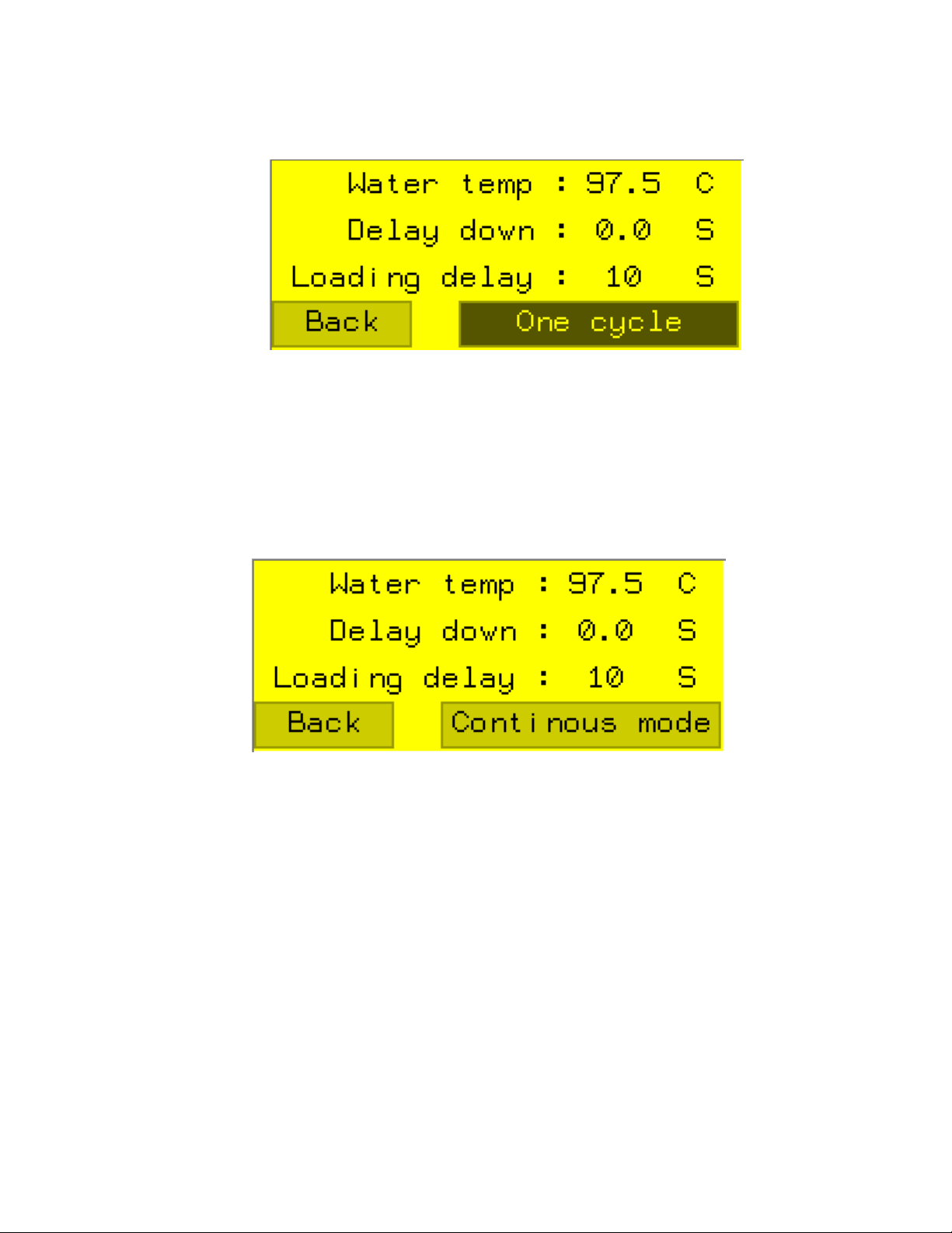
down position and the delay at t he up pos i tion for the loading (continuous
mode.
• When the water temperature s et point is reached, you can st ar t to supply
your DT-10 with some bags with your product in it. If the bags are not
enough shrunk, increase t he bottom pause time or increase temperature,
and try some other bags. Repeat this step until your bags are well shrunk.
The recommended temperat ur e i s ar ound 90°C – 95°C.
• In ONE CYCLE mode, the machine will do one complete cycle and then
stop. You need to press the ST A R T/STOP button to do t he cycle. In
CONTINOUS MODE mode, the mac hine will cycle by itself. You can stop
the CONTINOUS movement by pressing the START/STO P button.
• To stop the heating, press the POWER OFF button on the main s creen.
6
Page 7

Section 2- Troubleshooting
• If the DT-10 doesn’t heat t he water
o Check water level inside the DT-10. The LOW water message should not
show.
o Check the temperature set point.
o Check F1 fuse continuity.
o Check the water level switch o peration.
o Check the temperature sensor.
• If the plateau movement doesn’t work
o Check F2 fuse continuity.
o Check the limit switch function
o Check the variable fr equency drive for errors
• If the water reservoir does n’t fill
o Check water inlet ball valve
7
Page 8

Section 3- Maintenance
CAUTION
• To prevent personnel other than those involved in maintenance and
inspection work from turning the power ON while maintenance and
Failure to observe this caution could result in fire, product failure or
d to fire, product failure or
malfunction.
inspection is in progress, place signs stating “DO NOT TURN THE
POWER ON” or words to that effect at the primary power supplies of
related control panels and ot her relevant locations.
Failure to observe this caution could lead to electric shock.
• Do not install or remove boards, wiring, connectors, etc, while the power
is ON.
Failure to observe t his caution c ould l ead to e lect ric shock , produc t fai lure
or malfunction.
• Do not let foreign matt er such as electrical wire scrap ent er the unit.
malfunction.
• Be sure to check the following points after completing maintenance and
inspection work:
1. Check that all fastening bolts are tightened.
2. Check that no tools or other objects have been left inside the control
panel.
3. Check that the control panel door is closed properly.
Failure to carry out thes e checks cou ld lead to elec tric shock, injuries, fire
or malfunction.
• Do not change the set values of the devices, vari able resistors , etc, in the
control panel.
Failure to observe this caution could lea
3.1. Reservoir cleaning
•
Drain the water using the manual valve on the side of the mac hine
•
Remove the roller conveyor
•
Unbolt the conveyor plateau from the driving post
•
Clean the reservoir and conv eyor using mild detergent. Do not directly
hose down the machine
•
Do the reverse operation to reassemble the conveyor
8
Page 9

3.2. Gear box Oil change
• The gear unit is filled with mineral oil, the lubricant should be replaced
at least after every 10,000 oper ating hours or after every two years.
Often gear reducers are exposed to extreme ambient condi tions,
hostile environm ents, wet conditions, or dirty and dus ty operating
areas. Especially in these situations, it is important to establish a
condition-based oil ser vice interval.
• Standard Oil Fill. ISO VG 220, Mineral Oil
9
Page 10

Section 4- Mechanical drawing and parts list
MECHANICAL DRAWINGS
10
Page 11

005D1398
2
2
1
4
1
ITEM PART # DESCRIPTION QT.
1 005D1395 BODY ASS'Y 1
2 005D1396 WORKING BED ASS'Y 1
3 005C1410 ELECTRICAL BOX PRE-ASSY 1
4 005B1415 WORKING BED ASS'Y 1
LET. MODIFICATION
DATE
INT.
3
MACHINE
PART
ITEM
MAT.
DT-10
DT-10
CNC
DWG BY
APP. BY
AG
DEPT. TOL.
USINAGE
TOLERIE
SOUDAGE
DATE
15-01-21
DATE
METRIC
INCH
± 0.1
± 0.004"
±
0.5
±
0.020"
±
0.
5
±
0.020"
N.T.S.
DEPT.
NO.
005D1398
SIPROMAC
ST-GERMAIN DE GRANTHAM
QUEBEC CANADA
M
QTY.
1
Page 12

005D1395
1/2
ITEM PART # DESCRIPTION QT.
6
10
1 001B6443 BACK COVER BODY 1
2 001B6608 ELEMENT COVER DOUBLE 3
3 002A4148 LEVEL PLUG 1
4 004A4125 CONTROL INSERT 1
5 004A4130 FLANGE PIPE 2
11
6 004B4124 RACK GUARD 1
7 004B4126 ELEMENT COVER BRACKET 3
8 004C4000 TROUGH ASS'Y 1
9 004D3995 BODY ASS'Y 1
10 005A1414 MOTION ASSY 1
11 009A0232 ELEMENT 3
12 026-0110 BLACK CAP PUSH BUTTON (WATER) 1
13 026-0150 EMERGENCY BUTTON (PULL-PUSH) 1
8
14 031-0010 WATER LEVEL SENSOR 1/8'' NPT 1
13
15 031-00115 TEMPERATURE PROBE (3 WIRES) 1
16 036-0390 CABLE CONNECT.3/8"-1/2"METAL 3
17 040-0075 HMISTO511 1
21
18 051-01385 SCREW 10-24 x 1/2"FLAT-UND. PHIL S/S 12
18
19 051-0143 SCREW 10-24 x 3/8" PAN PHIL S/S 7
20 051-0162 SCREW 10-24nc. X 5/8" SKT S/S 3
21 051-0186 SCREW 1/4-20 x 1/2"TRUSS PHIL S/S 7
5
22 051-0189 BOLT 1/4-20 x 5/8" HEX S/S 1
23 051-0233 SCREW 1/4-20 X 1-1/4'' PAN PHIL S/S 2
24 051-0298 BOLT 5/16"-18 x 5/8" HEX S/S 16
17
12
25 051-0580 NUT 1/4"-20 S/S 1
26 051-0730 WASHER #10 FLAT S/S 6
2
27 051-0740 WASHER 1/4" FLAT S/S 3
28 051-0760 WASHER 5/16" FLAT S/S 13
10
29 057-00055 TWO ARM KNOB 1/4"-20 NYLON 1
30 100-0075 STREET ELBOW 1/2" NPT SS 2
31 100-01065 RED. COUPLING 1-1/4'' MNPT X 1/2'' FNPT
1
SS
32 102-0370 MALE CONN.1/8 MNPTX1/4 T.QUICK 1
36
33 105-0450 METAL CABLE CLAMPS #6 SS 1
34 107-0035 BALL VALVE 1/2 NPT SS WITH LOCKING 2
35 130-4PHB 4" SWIVEL CASTER W/BRAKE 2
36 130-4PHO 4" SWIVEL CASTER W/O BRAKES 2
LET. MODIFICATION
DATE
INT.
35
MACHINE
PART
ITEM
MAT.
DT-10
BODY ASS'Y
CNC
3D DWG BY
2D DWG BY
AG
AG
DEPT. TOL.
USINAGE
TOLERIE
SOUDAGE
DATE
15-01-29
DATE
15-01-29
METRIC
INCH
± 0.1
± 0.004"
±
0.5
±
0.020"
±
0.
5
±
0.020"
N.T.S.
DEPT.
NO.
005D1395
SIPROMAC
ST-GERMAIN DE GRANTHAM
QUEBEC CANADA
M
QTY.
1
Page 13

005D1395
2/2
34
30
DETAIL A
5
DETAIL C
7
21
18
2
16
23
B
29
32
3
14
15
31
15
A
22
25
DETAIL B
10
33
DETAIL D
C
24
28
D
MACHINE
DT-10
PART
ITEM
MAT.
BODY ASS'Y
CNC
3D DWG BY
2D DWG BY
AG
DEPT. TOL.
USINAGE
TOLERIE
SOUDAGE
DATE
15-01-29
DATE
METRIC
INCH
± 0.1
± 0.004"
±
0.5
±
0.020"
±
0.
5
±
0.020"
N.T.S.
DEPT.
NO.
005D1395
SIPROMAC
ST-GERMAIN DE GRANTHAM
QUEBEC CANADA
M
QTY.
1
Page 14

005D1396
ITEM PART # DESCRIPTION QT.
1 002B4074 WORKING BED STOPPER 2
2 002B4153 REAR BED STOPPER 2
5
6
87 9
3
3 004C4006 BASKET ASS'Y 1
4 004C4007 BASKET SUPPORT ASS'Y 1
5 004C4010 WORKING BED COVER ASS'Y 1
6 002B4076 LOCK SHAFT COVER WORKING BED 1
7 056-9201 BLACK PHENOLIC KNOB 3/8-16 (OD 1-3/4") 1
8 056-0315 EXT. RETAINER RING 3/8" S/S 1
9 077-01021 SPRING C 0480-045-1500 S COMP. 1
10 051-0757 WASHER 1/4" FLAT THICK S/S 4
11 051-0190 BOLT 1/4-20 x 3/4" HEX S/S 4
12 051-0780 WASHER 3/8" FLAT S/S 5
13 051-0360 BOLT 3/8"-16nc. X 1" S/S 3
14 051-0622 NUT 3/8"-16nc. NYLON LOCK S/S 2
1312
4
13 14
12
LET. MODIFICATION
11
10
2
MACHINE
DT-10
PART
1
DATE
INT.
ITEM
MAT.
WORKING BED ASS'Y
CNC
DWG BY
APP. BY
AG
DEPT. TOL.
USINAGE
TOLERIE
SOUDAGE
DATE
15-01-21
DATE
METRIC
INCH
± 0.1
± 0.004"
±
0.5
±
0.020"
±
0.
5
±
0.020"
N.T.S.
DEPT.
NO.
005D1396
SIPROMAC
ST-GERMAIN DE GRANTHAM
QUEBEC CANADA
M
QTY.
1
Page 15

005B1415
ITEM PART # DESCRIPTION QT.
1 002B4073 ROLLER SHAFT 25
2 002B4075 ROLLER STOPPER 2
3 002C4062 CONVEYOR ROLLER 225
4 004C4004 CONVEYOR FRAME 1
5 051-01385 SCREW 10-24 x 1/2"FLAT-UND. PHIL S/S 8
3
2
LET. MODIFICATION
1
5
4
DATE
INT.
MACHINE
PART
ITEM
MAT.
DT-10
WORKING BED ASS'Y
CNC
3D DWG BY
2D DWG BY
AG
AG
DEPT. TOL.
USINAGE
TOLERIE
SOUDAGE
DATE
15-01-21
DATE
15-01-21
METRIC
INCH
± 0.1
± 0.004"
±
0.5
±
0.020"
±
0.
5
±
0.020"
N.T.S.
DEPT.
NO.
005B1415
SIPROMAC
ST-GERMAIN DE GRANTHAM
QUEBEC CANADA
M
QTY.
1
Page 16

005C1410
ITEM PART # DESCRIPTION QT.
10 036-0415 WIRE CONNECTOR 1/2NPT CD16 + O-RING
+NUT
11 036-0420 PRESSE-ÉTOUPE CD21 1
5
3
4
5
ITEM PART # DESCRIPTION QT.
1 004D3996 ELECTRIC BOX ASS'Y 1
6
2 004D3999 COVER ELECTRIC BOX ASS'Y 1
3 001C6444 BACK PLATE ELECTRIC BOX 1
4 051-0740 WASHER 1/4" FLAT S/S 4
5 051-0580 NUT 1/4"-20 S/S 8
6 052-0420 SCREW 1/4"-20 N.C x 3/4" PAN SLOT BRASS 2
7 051-01385 SCREW 10-24 x 1/2"FLAT-UND. PHIL S/S 8
8 051-0730 WASHER #10 FLAT S/S 8
9 051-0572 NUT #10-24 NYLON LOCK S/S 8
10
2
LET. MODIFICATION
DATE
INT.
11
1
9
8
7
6
MACHINE
DT-10
PART
ELECTRICAL BOX PRE-ASSY
ITEM
MAT.
CNC
DWG BY
APP. BY
AG
DEPT. TOL.
USINAGE
TOLERIE
SOUDAGE
DATE
15-01-21
DATE
METRIC
INCH
± 0.1
± 0.004"
±
0.5
±
0.020"
±
0.
5
±
0.020"
N.T.S.
DEPT.
NO.
005C1410
SIPROMAC
ST-GERMAIN DE GRANTHAM
QUEBEC CANADA
M
QTY.
1
Page 17

005B1414
ITEM PART # DESCRIPTION QT
12 002A4238 IDLER SHIM 4
13 002A4154 SPACER 4
14 051-0760 WASHER 5/16" FLAT S/S 8
15 051-0600 NUT 5/16" -18 S/S 4
16 051-0305 BOLT 5/16"-18 NC X 1" S/S 4
17 051-0313 BOLT 5/16"-18 x 2-1/2'' HEX S/S 4
18 001A6930 END PLATE 1
19 051-01845 BOLT 1/4"-20 x 1/2"CAP HEX SKT.S/S 2
20 001A6931 LARGE RACK ROLLER WASHER 2
12
2
3
20
10
16
ITEM PART # DESCRIPTION QT
.
1 002A4152 ROLL IDLER 3
2 002B4151 RACK 1
3 002B4150 LARGE RACK ROLLER 1
4 037-09192 SHAFT MOUNTED GEAR MOTOR
1/2HP FRAME 63
5 004B4129 PINION 1
6 051-0622 NUT 3/8"-16nc. NYLON LOCK S/S 4
7 004B4127 MOTION PLATE ASSY 1
8 051-0783 WASHER 3/8" FLAT THICK S/S 8
9 051-0601 NUT 5/16"-18 NYLON LOCK S/S 4
10 051-0179 SCREW ¼"-20nc. X 3/8" SKT SET S/S 2
11 026-0735 LIMIT SWITCH TELEMECANIQUE 2
15
14
.
1
7
6
13
LET. MODIFICATION
DATE
INT.
4
9
5
11
11
1
17
8
18
MACHINE
19
PART
DT-10
MOTION ASSY
ITEM
MAT.
CNC
DWG BY
APP. BY
YF
DEPT. TOL.
USINAGE
TOLERIE
SOUDAGE
DATE
DATE
METRIC
± 0.1
±
0.5
±
0.
15-01-29
INCH
± 0.004"
SIPROMAC
±
0.020"
5
±
0.020"
ST-GERMAIN DE GRANTHAM
QUEBEC CANADA
N.T.S.
M
NO.
005B1414
QTY.DEPT.
1
Page 18

Section 5- Electrical drawing and parts list
ELECTRICAL DRAWINGS
11
Page 19

0 76
1
2
4
5
8 93
L1
L2
L3
GND
-F1
30 A
-C1
/1.2.3
12
1/L12/T1
34
3/L24/T2
56
5/L36/T3
-F2
7 A
-C2
/1.2.3
12
1/L12/T1
34
3/L24/T2
56
5/L36/T3
-F3
-PS1
/
L1
/
L2
/
L3
12
GND
34
-PLC0
L N
GND
/1.2.0
U
/1.2.7
x1x2
-E1
x1 x2
-E2
x1x2
-E3
FV1
-M2
L1 L2 L3
T1 T2 T3
U1
V1
W1
M
3
PE
-HMI1
-F4
201
12
202
24V
+
COM1 USB1 USB2
0V
-
PE
FG
HMISTO
SERIAL
24VDC
0VDC
/ 1.2.5
/ 1.2.4
Modification
Date
Name
Date
Ed.
Appr
Original
02/03/2015
msylvain +
SIPROSHRONK DT-10
Replacement of
Replaced by
SIPROMAC II INC.
240 boul. Industriel
St-Germain-de-Grantham, J0C
1K0, Qc, Canada
Alimentation
006-5000
1.1
=
Page
Page
1
4
Page 20

0 76
1
2
4
5
8 93
-PLC0
/1.6
.7
OUTPUT
COM0
Q0.0
Q0.1
Q0.2
Q0.3
203
11
12
13
14
FV1
24V+
LI1
LI2
LI3
LI4
1.8
0VDC
1.8
24VDC
E-STOP
WATER-LEVEL
PLC0
/1.6
.0
INPUT
1
I0.0
1
START-STOP
2
I0.1
I0.2
3
I0.3
COM1
Q0.4
Q0.5
Q0.6
1
TOP-LIMIT
4
DRIVE CONTACTOR
I0.4
-C2
8
A1 A2
HEATING CONTACTOR
BOTTOM-LIMIT
5
I0.5
-C1
9
A1 A2
202
COM
-PT100
PLCA
AI0_A
1.1
Modification
Date
Name
Date
Ed.
Appr
Original
AI0_B
AI0_B
02/03/2015
msylvain +
SIPROSHRONK DT-10
Replacement of
Replaced by
SIPROMAC II INC.
240 boul. Industriel
St-Germain-de-Grantham, J0C
1K0, Qc, Canada
Automate
006-5000
2
=
Page
Page
1.2
4
Page 21

DT‐1012351 26‐02‐2014
e
R
ItemId Qte Unit
Note ItemDescription1
034‐0755 3 UN F1 FUSEHOLDER60A/600V3POLECLASSJ
034‐0580 3 UN F1 FUSELPJ‐SPI45A/600VTIMEDELAY
025‐0401 1 UN C1 MOTORCONTACTOR12A24VDCLOWCONSUMPTION
039‐0127 3 UN E1,E2,E3 ELEMENT4000W,230V,.440''X40''U(DT‐10)
034‐0755 3 UN F2 FUSEHOLDER30A/600V1POLEUSM1
034‐0460 3 UN F2 FUSEMIDGET7A/600VFASTACTING
025‐0400 1 UN C2 MOTORCONTACTOR9A24VDCLOWCONSUMPTION
041‐0112 1 UN FV2 FREQ.VARIATOR1/2HP200/250V3PH
037‐09192
1 UN M2 SHAFTMOUNTEDGEARMOTOR1/2HPSIZE63
034‐0740 3 UN F3,F4 FUSEHOLDERM4/8SF
028‐0070 2 UN F3,F4 SEPARATORM4/8SF
034‐0230 2 UN F3 FUSE5X20MM3A/250VFASTACTING
040‐0067 1 UN PS1 POWERSUPPLY70W‐3A,TERMINALSTANDARD
034‐0205 1 UN F4 FUSE5X20MM1A/250VT‐DELAY
040‐0072 1 UN PLC0 PLC16IO7outrelay,9in,Ethernet,100‐240VAC
040‐0074 1 UN PLCa CARTOUCHE2ENTREETEMPERATURE
040‐0075
1 UN HMI INTERFACEOPERATEUR3.4INMONOCHROMESERIAL
031‐0045 1 UN WATERTEMP. RTDPT1003‐WIRE1/4inODx6in6ftLEADS
031‐0046 1 UN WATERTEMP. COMPRESSIONFTG1/2inMNPTFOR1/4inODTEMPERATU
026‐0110 1 UN START/STOP SILICONCAPPUSHBUTTON(WATER)
026‐0020 1 UN START/STOP 1N.O.CONTACTBLOCK
026‐0150 1 UN E‐STOP EMERGENCYBUTTON(PUSH‐PULL)
026‐0025 1 UN E‐STOP 1N.CCONTACTWITHBASE
026‐0735 2 UN TOPANDBOTTOM LIMITSWITCHTELEMECANIQUE/ROLLERLEVER
031‐0044 1 UN WATERLEVEL WATERLEVELSENSOR1/8''NPT
028‐0023 3 UN TERMINALBLOCKM16/12
028‐0024 2 UN GROUNDTERMINALBLOCKM10/10P
028‐0008 8 UN TERMINALBLOCKM4/6
028‐0060 4 UN SEPARATORM4/6
 Loading...