

Page 1
1
VACCUM MACHINE
600A
OWNER’S MANUAL
Page 2

2
Page 3

3
IMPORTANT SAFETY INSTRUCTIONS
SAVE THESE INSTRUCTIONS
This symbol points out important safety instructions which, if not follow ed, could endanger
the personal safety and/or property of yourself and others. Read and follow all instructi ons
in this manual before attempting to operate your machine.
Failure to comply with these instructions may result in personal injury.
General Operation
• Read, understand, and follow all instructions in the manual and on the machine before
starting. Keep this manual in a safe place for further and regular reference and for ordering
replacement parts.
• Only allow responsible individuals familiar with the instructions to operate the machine. Be
sure to know controls and how to stop the machine quickly.
• Never put your hands near moving parts.
• Only allow qualified individuals for the maintenance of your machine.
• Remove all obstacles, which may interfere with the machine functions.
• Clear the work area such as electrical wires, buckets, knives etc.
• Be sure that everyone else is clear of your work area before operating the machine.
• Do not sit nor stand on the machine.
• Always turn off the machine after your work is done. Never leave a running machine
unattended.
• Always disconnect and wait till the machine has cooled before attempting any maintenance.
• Do not wear loose fitting clothes or jewelry as they may get caught in moving parts of the
machine.
• Always wear security shoes, to prevent injury caused by moving the machine or objects falling
from the machine.
• Never exceed the time limit to seal, which is recommended by the manufacturer. This is to
avoid any damage that may be caused to the sealing bars and to eliminate the risk of fire in
the machine. Thus avoiding corporal burns.
• Never touch the sealing bars after they have been used, this will avoid corporal burns. Wait a
few minutes to let the machine cool down before touching.
• Always make sure that the sealing bars are well installed in their "Guide Blocks" before
starting a cycle.
• Never incline the machine more than 30 degrees, it may tip over and hurt someone seriously.
• Work only in daylight or good artificial light.
Do not operate the machine while under the influence of alcohol or dr ugs!
Page 4

4
Service
• Use proper containers when draining the oil. Do not use food or beverage containers that may
mislead someone into drinking from them. Properly dispose of the containers, or store in a
safe place immediately following the draining of the oil.
• Prior to disposal, determine the proper method to dispose of waste from your local office of
Environmental Protection Agency. Recycling centers are established to properly dispose of
materials in an environmentally safe fashion.
Do not pour oil or other fluids into the ground, down a drain or into a body of
water
.
Warning-Your responsibility:
This machine should only be operated by personal who c an read, understand and respec t
warnings and instruc tions regarding this machine in the owners manual. Save these
instructions for future reference.
Page 5

5
VACUUM PACKAGING MACHINE
I OPERATION INSTRUCTIONS
II MECHANICAL
A- Front view general assembly drawing
B- Rear view general assembly drawing
C- Cover adjustment procedure
D- Central shaft assembly drawing
E- Seal bar assembly drawings
(twin seal)
F- Seal bar assembly drawings
(electrical bag cut option)
G- Seal bar assembly drawings
(top and bottom sealing option)
H- Gas injection kit installation drawing
(gas injection option)
III ELECTRICAL
A- Electrical drawings
IV PNEUMATIC
A- Pneumatic drawing
MODEL 600A
(MC-40 SIPROMAC)
GENERAL TABLE OF CONTENTS
Page 6

6
VACUUM PACKAGING MACHINES
OPERATION INSTRUCTIONS
TABLE OF CONTENTS
1. Setting up the machine
2. Electrical connection
3. Operation
3.1 Working principles
3.2 Special packaging
3.2.1 Gas flushing
3.2.2 Top and bottom sealing (bi-active)
3.2.2 3.2.3 Electrical bag cut
3.3 Setting of digital controls
3.4 Daily cleaning
4. Trouble shooting
4.1 Failure during a packaging cycle
4.2 Insufficient vacuum
4.2.1 Leakage in the bag
4.2.2 No leakage in the bag
4.2.3 Insufficient vacuum in the chamber
4.3 Faulty seal
4.3.1 Insufficient seal
4.3.2 No seal
4.3.3 Permanent sealing current
4.3.4 Seal does not stick
4.4 Fault in the valves
4.5 Control board failure
5. Regular maintenance
2010-08-30
Page 7

7
VACUUM PACKAGING MACHINES
1. SETTING UP THE MACHINE:
Before choosing the site for the machine, please consider that y ou wil l also need room
for packaged and non-packaged products apar t from the space needed for the ma chine
itself.
Keep in mind that the machine must not be set up upon uneven ground. Especially wi th
mobile models, the weight of the pump mig ht then cause warping of the machine. Then
the lid will not fit correctly.
Before starting to work, check the oil view glass on the pump, if there is a sufficient
quantity of oil in the pump. Never use oil other than recommanded by the producer.
Never exceed maximum quantity of oil indicated, when adding or changing oil. Verify
weekly.
Normal ambient temperature for the vacuum pump is between 10 to 70oC.For
temperature below 10oC; it is recommended to use synthetic oil. Please consult
factory and pump manufacturer manual for more information or when ambient
temperature are outside normal limits
2. ELECTRICAL CONNECTION:
Electrical connections must be made by qualified personnel. This person must make
sure that the electrical entries corresponds to the proper voltage and amperage of the
machine. GROUNDING INSTRUCTIONS: This appliance must be connected to a
grounded, metal, permanent wir ing system; or an equipment-grounding conductor must
be run with the circui t conductors and connected to the equipment-groundi ng terminal or
lead on the appliance. A quali fied electrici an should be c onsulted i f there is any doubt
as to whether an outlet box is properly grounded.
All vacuum machines are supplied with an electrical schematic drawing.
An important step in connecting the machine is to make sure that the pump turns in
its correct rotation.
The pump should not rotate more than 3 to 4 sec onds in the wrong rotation or it
may cause serious damage. The proper r ota ti on i s indicated by an arrow on the
pump motor.
3. OPERATION:
3.1 Working principles:
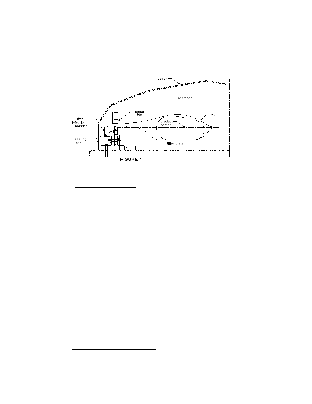
A vacuum packaging cycle is made of 3 stages. First the vacuum is made, the air is
completly taken out of the chamber and from bag contai ning the product. (See figure 1 ).
Then it is possible to inject neutral gas from the nozzles, if the product is delicate.
Finally, a mechanism pushes the sealing bar to the rubber support to seal the bag.
SIPROMAC INC.
Page 8
8
To obtain nice packages, the products and the bags have to be of proportional sizes. The
bag's opening should never exceed 50 cm(2") past the seal bars. The product should be
centered in height in relation to the seal bar by adjusting the spacers provided.
To obtain a good seal, make sure that no residue of fat is left between the bag's inner
sides where sealing is done.
3.2 Special packaging:
3.2.1 Gas flushing (option):
There is an atmospheric pressure of 1 kg/ sq. cm (14 lbs/sq. inch) upon products when
fully evacuated. Products which can be damaged by high pressure must be packaged
with a partial vacuum, or the pressure must be counterbalance by inflating the bag with
gas (nitrogen or carbon dioxide) before sealing after evacuation.
For gas flushing, the bags are placed on the sealing bars, the open end placed over
the gas nozzles mounted alongside the sealing bar. After evacuation, the vacuum
valve closes and the gas valve opens. Gas time (sec.) can be set in the program
menu.
The necessary gas tank and pressure valve mounted on tank is not supplied, The
pressure of the gas regulator should be set at approximately 1/3 kg/sq. cm
( 5 lbs/sq.inch.). Each machine has an adaptor for gas connection when gas flush
option is ordered.
3.2.2 Top and bottom sealing (optional):
When sealing aluminium laminate bags (especially bags for e.g. coffee) it is imperative
to have an upper and a lower sealing bar.
3.2.2 Electrical bag cut (optional):
This option is used to obtain a package that the excess bagtail is cut off close to the
seal (cannot be used with top and bottom sealing).
Page 9

9
3.3 Vacuum packaging operation:
3.3 Vacuum packaging operation:
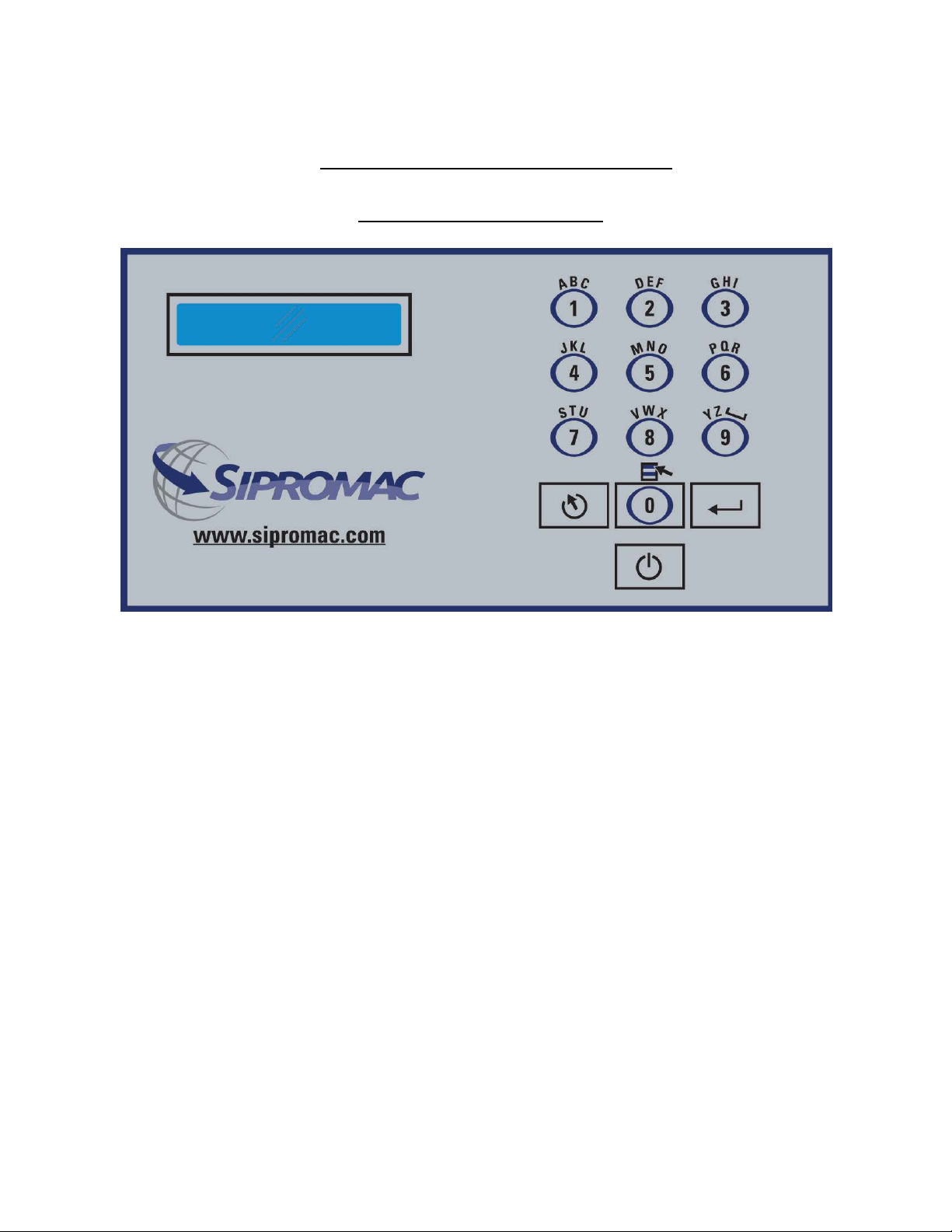
Note: Refer to the menus structure on page 14 and the keyboard detail on page 15.
3.3.1 Basics:
Use key "POWER" to power ON / OFF the vacuum packaging machine. When the unit
is energized, the identification of the last executed program is displayed on LCD screen.
Use the "ESC" key to change over from the programs menu to the functions menu and
from the functions menu to the programs menu.
In functions menu, use key "SELECT" to select a function and key "ENTER" to accede
and executed the selection.
In programs menu, use key "SELECT" to select a program and key "ENTER" to accede
and modify the selection.
In programs submenu, use key "ENTER" to pass over the parameters and point to the
following one; the parameters are blinking to point out the acquisition mode. A return to
programs menu is performed automatically following the last parameter acquisition.
In program submenu, use key "ESC" to get back to the programs menu.Strike any key
to clear the error messages which may be displayed on LCD screen.
3.3.2 Functions:
3.3.2.1 Create a program:
When executing the "create a program" function, the program submenu is
acceded, starting with the identification. The initial identification "Pxx NO NAME"
is given to the program and all parameters are established to zero; the program
number is allocated automatically.
3.3.2.2 Delete a program:
When executing the "delete a program" function, the programs menu is acceded
and the number of the first program in memory is blinking to point out the
deletion mode. Use key "SELECT" to select a program and key "ENTER" to
accede and confirm deletion of the selection. Use key "ESC" to unconfirm a
deletion and to leave the function. When leaving the function, the number of the
actual program on LCD screen cease to blink.
3.3.2.3 Select operating mode:
When executing the "select operating mode" function, which is available only for
the automatic units, the actual selection is blinking to point out the acquisition
mode. Use key "SELECT" to get through the operating modes, which are
automatic, semi-automatic and manual; the validation of the selected operating
mode is performed automatically. Use key "ESC" or "ENTER" to leave the
function and get back to the program menu.
Page 10

10
3.3.3 Programs menu:
3.3.3.1 Program identification:
For a selected program, set the identification, using the numeric keyboard
characters chart; press numeric key untill the desired character is selected
(4 times for the numeric value). Use key "ENTER" to validate the character and
to validate the characters string at the end(the new characters string is blinking).
In a middle of an acquisition, use key "ESC" to come backward and erase one or
several characters.
Example: EXAMPLE 1 keys 2, 2, ENTER E
(9 characters) keys 8, 8, 8, ENTER X
keys 1, ENTER A
keys 5, ENTER M
keys 6, ENTER P
keys 4, 4, 4, ENTER L
keys 2, 2, ENTER E
keys 9, 9, 9, ENTER space
keys 1, 1, 1, 1, ENTER 1
key ENTER to validate the characters string
3.3.3.2 Vacuum level setting:
For a selected program set the vacuum level, starting with the values; the
decimal point is automatically inserted following the second digit entry and the
validation is automatically performed following the third digit entry (the new
vacuum level is blinking). The vacuum level is rounded off to the nearest half
value. In the middle of an acquisition, use key "ENTER" to validate the vacuum
level and key "ESC" to come backward and start over with a new acquisition
(the old vacuum level is blinking). Set vacuum level to zero to bypass the
pressure transducer and proceed only using the vacuum plus time.
Examples: 90.0% keys 9, 0, 0 or 9, 0, ENTER or
keys 9, 0, 1 or 9, 0, 2 or 9, 0, 3 or 9, 0, 4
97.5% keys 9, 7, 5 or
keys 9, 7, 6 or 9, 0, 7 or 9, 0, 8 or 9, 0, 9
0.0% keys 0, 0, 0 or 0, ENTER
3.3.3.3 Vacuum plus time setting:
For a selected program set the vacuum plus time, in seconds; the validation is
automatically performed following the second digit entry (the new vacuum plus
time is blinking). In a middle of an acquisition, use key "ENTER" to validate the
vacuum plus time and key "ESC" to come backward and start over with a new
acquisition (the old vacuum plus time is blinking).
Examples: 1s keys 0, 1 or 1, ENTER
15s keys 1, 5
Page 11

11
3.3.3.4 Gas flush level setting:
For a selected program set the gas flush level following the same procedure as
for the vacuum level; the maximum gas flush level setting is 10% below the
vacuum setting.
3.3.3.5 Sealing time setting:
For a selected program set the sealing time, starting with the seconds; the
decimal point is automatically inserted following the first digit entry and the
validation is automatically performed following the third digit entry (the new
sealing time is blinking). The sealing time is truncated to the nearest half
hundredth. In a middle of an acquisition, use key "ENTER" to validate the sealing
time and key "ESC" to come backward and start over with a new acquisition
(the old sealing time is blinking).
Examples: 4.50s keys 4, 5, 0 or 4, 5, ENTER or
3.3.4 Vacuum cycle execution:
For the manual units and the automatic units set on manual, close the cover to initiate a
vacuum cycle. For the automatic units set on semi-automatic or on automatic, use push
button "STOP / START" to initiate or interrupt a vacuum cycle. A selected program can
be initiated only in the programs menu, when no modifications are in progress, and the
access to the other programs and functions is denied. During cycle execution the
operation status is sequencally displayed on LCD screen, except for the parameters
established to zero, which are not displayed:
- chamber vacuum level during vacuum sequence,
- vacuum plus time status during vacuum plus sequence,
- chamber vacuum level during gas flush sequence,
- sealing time status during sealing sequence,
- chamber vacuum level during atmosphere sequence.7
During cycle execution, use key "1" to abort the vacuum sequence and execute the
following sequence, which is gas flush or sealing, and key "ENTER" to accede and
modify the program; the parameters become valid only for the following vacuum cycles.
3.3.5 System monitor:
To accede the diagnostics menu, power up the vacuum packaging machine while
keeping pushed in the "ESC"key. Use key "SELECT" to select the system monitor
function and key "ENTER" to accede and visualize the monitored parameters. Use key
"SELECT" to change over from the software revision, the amount of working hours
done and the amount of complete cycles performed since first initialization.
keys 4, 5, 1 or 4, 5, 2 or 4, 5, 3 or 4, 5, 4
2.35s keys 2, 3, 5 or
keys 2, 3, 6 or 2, 3, 7 or 2, 3, 8 or 2, 3, 9
0.00s keys 0, 0, 0 or 0, ENTER
Page 12

12
-MENUS STRUCTURE-
• Functions menu:
"F1 CREATE A PRGM"
"F2 DELETE A PRGM"
"F3 SELECT OPMODE" (automatic units only)
• Programs menu:
"Pxx NAME"
Program submenu:
"VACU UM: xx.x%" (10.0% - 99.5%)
"VACUUM PLUS: xxs"(0s - 99s)
"GAS FLUSH: xx.x%" (0.0% - 10% below the vacuum level) (units with gas option)
"SEAL TIME: x.xxs" (0.00s - maximum unit allocated setting)
"Pxx NAME" (12 characters)
• Diagnostics menu (keys "ESC" & "POWER" for access):
"DIAGNOSTICS MENU" (access code required)
"D1 INPUTS TEST"
"D2 OUTPUTS TEST"
"D3 MODEL SELECT"
"D4 GAS OPTION"
"D5 SEALING TIME"
"D6 COOLING TIME"
"D7 OFFSET CALIB.”
"D8 VACUUM SENSOR”
"D9 SIPROMAC PUB”
"D10 LOADING TIME" (automatic units only)
"D11 UNLOADNG TIME" (automatic units only)
"SYSTEM MONITOR" (no access code required)
"SOFTWARE: R x.xx"
"WORK HRS: xxxxx"
"CYCLES: xxxxxxx"
Page 13
13
-KEYBOARD DETAILS-
MC-40 CONTROLS
Page 14

14
WARNING: All electrical work describe d i n thi s brochure should be done by
a QUALIFIED and AUTHORIZED technician
.
3.4 Daily cleaning:
For hygenic cleanliness, it is imperative to clean chamber and spacers daily. Also clean
the lid rubber to assure tight seat of the lid.
Cleaning instructions for gas injection nozzl es: Periodically on a regular basis the gas
injection nozzles must be removed with the connection tube and soaked in a food grade
soap and water solution, then dried and re-installed.
4. TROUBLE SHOOTING:
4.1 Failure during packaging cycle:
4.1.1 "VACUUM ERROR" message is displayed on LCD:
No pressure variation is picked up by the PCB transducer during the vacuum sequence
within a preset period of time.
- Check vacuum lines for potential leaks or kinks.
4.1.2 "GAS FLUSH ERROR" message is displayed on LCD:
No pressure variation is picked up by the PCB transducer duringthe gas flush sequence
within a preset period of time.
- Check gas flush and vacuum lines for potential leaks or kinks.
4.1.3 "ATMOSPHERE ERROR" message is displayed on LCD:
No pressure variation is picked up by the PCB transducer during the atmosphere
sequence within a preset period of time.
- Check vacuum lines for potential leaks or kinks.
4.1.4 "COVER DOWN ERROR" message is displayed on LCD(manual units):
The input signal of the down position switch has been lost during cycle execution.
- Check limit switch adjustment.
Page 15

15
4.2 I nsufficient vacuum:
4.2.1 Leakage in the bag:
Most frequently, insufficient vacuum in bags is due to leakage in bag and not due to any
fault of the machine.
Pin-hole leak for which there is no obvious explanation is due to faulty bag material.
Pin-hole leak caused by sharp edge of the product (bone, etc.).Use bone-guard or
thicker film.
Tear in bag by careless handling (sharp edge on filling table, damage made by retailer
or customer).
Leakage in lateral or bottom seal, complain to supplier of bags or film.
4.2.2 No leakage in the bag:
Bag is too large, therefore the surplus of air remains visible (there is surplus of air in
0.4% of the bag volume in each bag). Use bags of suitable size.
Vacuum level is too low:
Pressure bar is jammed and closes opening of bag during evacuation.
4.2.3 Insufficient vacuum in chamber:
If troubles described under 4.2.1 and 4.2.2 do not apply, there is something wrong with
the evacuation.To find the leakage quickly, check for leaks with a precision vacuumeter,
going back step by step from the chamber to the pump.
At the chamber (measuring point at base of valve) at maximum time of evacuation. If
more than 6 torr, proceed directly to the pump, if more than 3 torr:have pump service by
pump supplier.If pressure at pump is good, reconnect hoses to pump and measure
again.
Verify at vacuum hose connections and valve connections.
When proceeding this way, starting from pump, loss of pressure per step must not
exceed 0.5 to 1 torr.
Caution:Verify connections of measuring equipment before verifing machine.
Most frequent points of leakage: lid gasket, damaged vacuum hose or loose hose
clamps.
Page 16

16
4.3 Faulty seal:
4.3.1 Insufficient seal:
Damaged teflon or silicone rubber.
Sealing pressure too low, bellows leaking or pressure bar jammed.
Leakers in seal: heating wire mechanically damaged (knicked) or silicone rubber
uneven.
4.3.2 No seal:
Sealing wire burnt.
Faulty contact in sealing circuit.
Sealing transformer burnt through.
Contactor does not work.
4.3.3 Permanent sealing current:
Contactor is jammed check sealing transformer for damage through overload.
4.3.4 Seal does not stick:
Insufficient layer of polyethylene (inferior quality of bags).
Seal area extremely contaminated by fat or meat juice. Use filling aid.
Sealing temperature is too low (when using very thick films).
Caution: Do not increase sealing time more than really necessary; higher temperature
4.4 Fault in the valve:
Vacuum or air valve does not open.
Check whether there is voltage on the magnetic valves during their period of operation. If
there is no voltage a wire is broken or the PC board is damaged.
Lid does not open at the end of the cycle; air enters, but there is still 20 - 40% vacuum in
chamber. Vacuum valve does not close.
will reduce working life of teflon and silicone rubber.
Page 17

17
4.5 MC4 0 Control board failure
NOTE:Refer to menu structure on page 13.
This board software is allowing access to a "Diagnostics Menu". Only qualified service
technicians are authorized to access this menu by entering a security password.
By acceding either the "D1 input test" feature or the "D2 output test" feature,a trained
technician will be able to quickly know the origin of the problem: pump, sealing system,
pneumatic problem, security switches problem, etc...
Keep in mind that in most cases trouble is due to a leakage, loose electrical connection or
evident dammage to the main components: vacuum pump, valves, electrical contactors,
thermal overload, fuses holder or transformer.
For assistance do not hesitate to contact your local service technicians.
5. Regular maintenance:
Routine controls to be made at regular intervals:
Check teflon for wear.
Check silicone rubber for burnt spots and smooth even position.
Check pressure bar for jamming.
Check lid sealing for damage and hardened spots.
Check switch-point of micro switch, adjust if necessary.
Check evacuation hose for damage (contraction of diameter, or abrasions).
Check vacuum connections for tightness.
Check oil in pump (oil level in view glass; add if necessary. Regular change of oil - necessity
indicated by change of color).
Check vacuum in chamber with precision vacuumeter.
Check function of cycle with various settings of timers.
Page 18

18
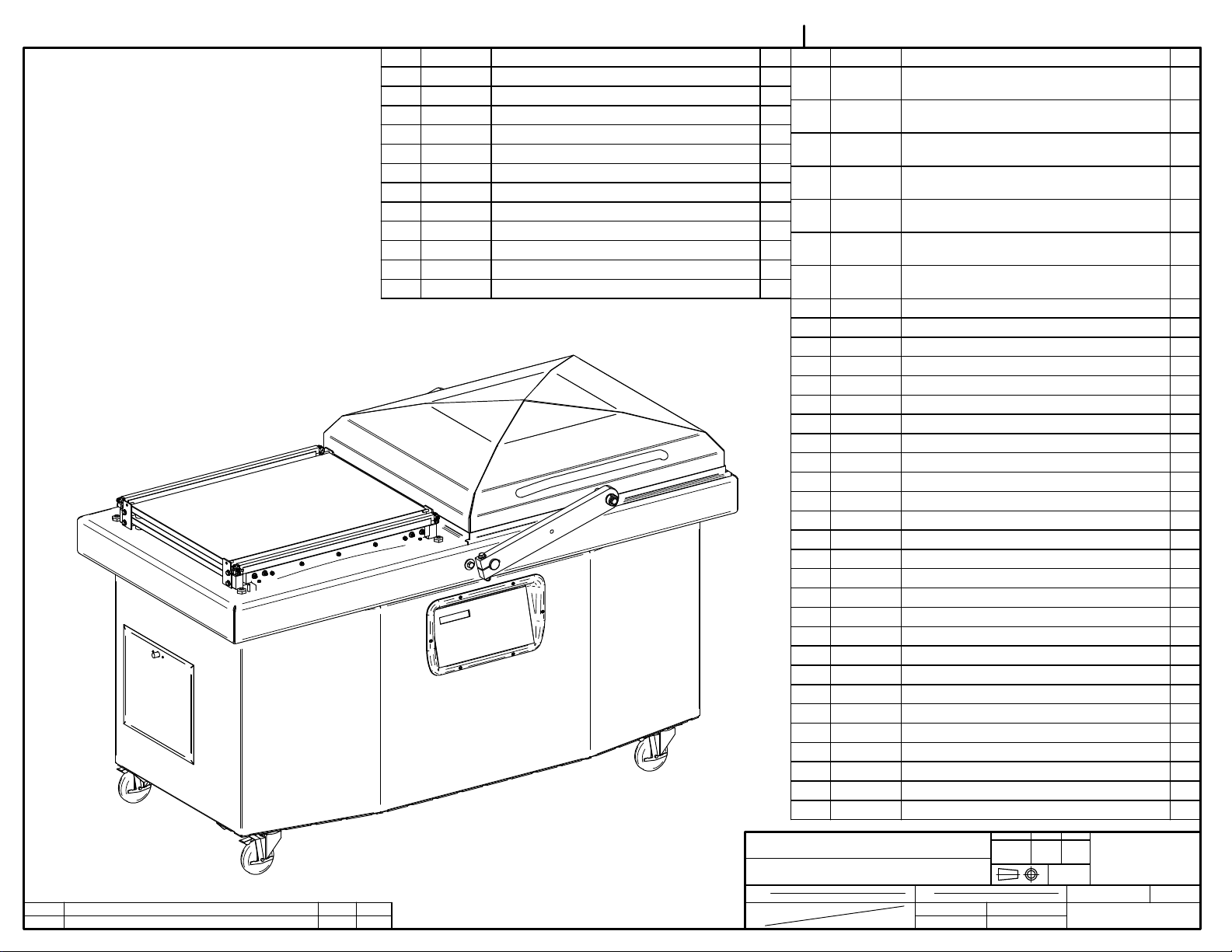
MODEL 600A
COVER ADJUSTMENT PROCEDURE
Reference Drawing:# 005C0324
# 004C0122
PROBLEM: MACHINE TABLE AND COVER SEEMS TO BE STRAIGHT, LID GASKET IS GOOD
BUT COVER DOES NOT SIT PROPERLY ON BOTH SIDES OF TABLE.
1. Floor should be flat (within 1/8" approx.).
2.2 Loosen the two bolts of the guide arm axis (See drawing #004C0122; items #23).
2.3 Now move the cover on each side and check how cover sits on the table. Distance
between table and lid gasket should be less than 1/16" approx. If so, go to step 3.0 for
guide arm adjustment. Otherwise go to step 2.4 for central arm adjustment.
2.5 When closing cover (guide arm axis still loose), if cover is not sitting properly on either the
front or rear of the table, you have to change the height of the flange bearings (See
drawing # 004C0122; item #12) until cover is seating properly on each side. Normally shaft
is centered in the table holes and the height is adjusted in a way that cover will slightly
touch the back side of the table first.
3. Adjustment of guide arm: Both length of the guide arm and position on the guide arm axis have to
be adjusted. Each of these should be adjusted separately. Fix the lower axis in a central position
(centered in the holes) then adjust guide arm length until cover sit correctly on the right side.
Move cover to the left side and check if cover sits correctly, if not move lower axis position and
change length of the guide arm. Move the cover back to its original position to confirm, normally
multiples tryout is required. Make sure there is no stress is transferred to the guide arm when
machine is operating, stress induced arm will cause premature component fail.
Page 19
19
MECHANICAL DRAWING
Page 20
004B4103, 004B4104, 004B4105 WAS A. 005F0561 WAS E
A
LET. MODIFICATION
14-05-27
DATE
ITEM PART # DESCRIPTION QT.
35 033-0021 MC-40 KEYBOARD "SUPPLY ONE" 1
36 036-0409 PRESSE-ETOUPE CD13 1
37 039-0191 THERMOSTAT HAMMOND 1
38 039-0192 HEATER 100W HAMMOND 1
39 051-0210 BOLT ¼"-20nc. X 1" S/S 6
40 051-0300 BOLT 5/16"-18 x 3/4" S/S 16
41 051-0601 NUT 5/16"-18 NYLON LOCK S/S 16
42 051-0740 WASHER 1/4" FLAT S/S 6
43 051-0760 WASHER 5/16" FLAT S/S 32
44 057-0460 PLUG 3/4" BLACK 1
45 104-0064 SILICONE TUBING 3/8'' OD x 3/16'' ID x 80mm 2
46 130-4PHB 4" SWIVEL CASTER W/BRAKE 4
SBU
INT.
MACHINE
PART
ITEM
MAT.
005D0324
1/5
ITEM PART # DESCRIPTION QT.
1 004A1125 UPPER SEAL BAR ASSEMBLY (E.C.O.) &
2
(TWIN)
2 004A4106 VACUUM/ATMOSPHERE VALVE (OPT
1
MUFFLER)
3 004A4107 VACUUM/ATMOSPHERE VALVE (OPT SOFT
1
AIR)
4 004A4108 VACUUM/ATMOSPHERE VALVE (OPT SOFT
1
AIR + MUFFLER)
5 004A4109 VACUUM/ATMOSPHERE VALVE (OPT
1
MUFFLER)
6 004A4110 VACUUM/ATMOSPHERE VALVE (OPT SOFT
1
AIR)
7 004A4111 VACUUM/ATMOSPHERE VALVE (OPT SOFT
1
AIR+MUFFLER)
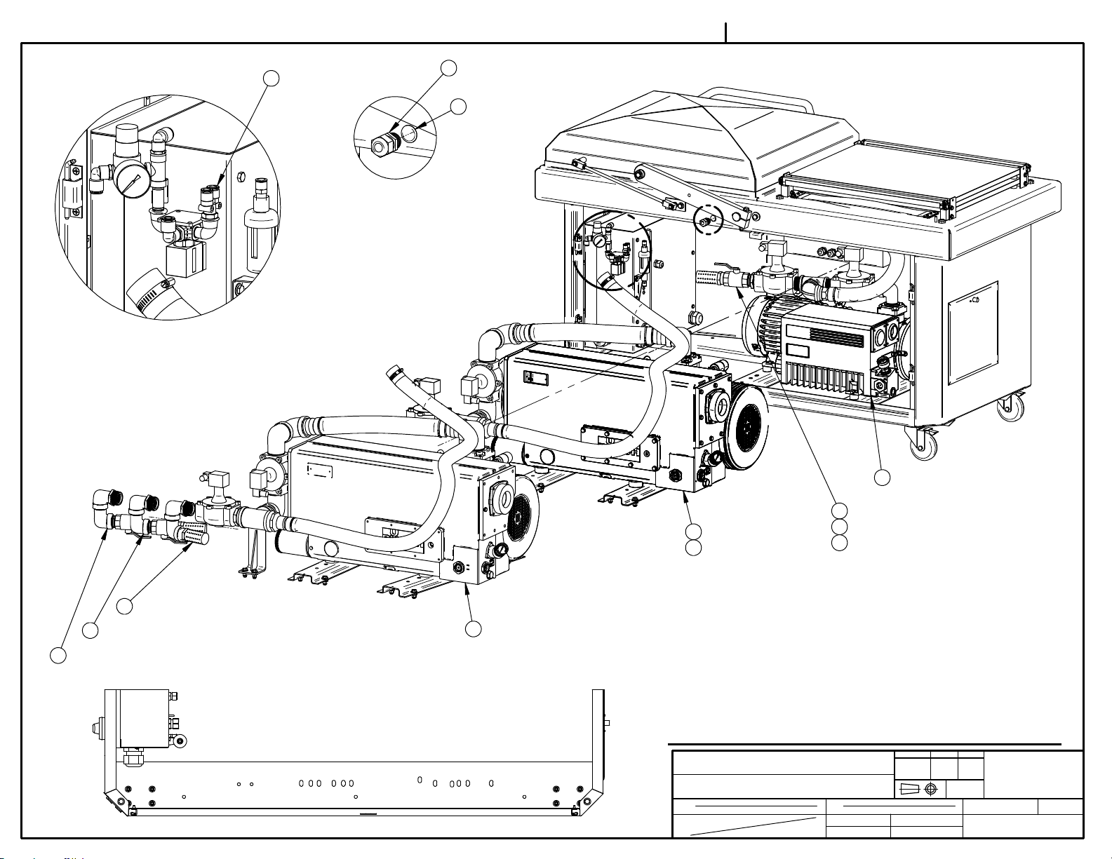
8 004A4141 PUMP "BUSCH" 305 M³ 1
9 004A4146 BASE MACHINE ASSEMBLY 1
10 004B1468 PUMP "BUSCH" 100 M³ ASSEMBLY 1
11 004B1469 PUMP "BUSCH" 165 M³ ASSEMBLY 1
12 004B1471 PUMP "BUSCH" 255 M³ 1
13 004B4103 AIR REGULATOR VALVE ASSY 1
14 004B4104 BELLOWS VALVE ASSY 1
15 004B4105 BELLOWS VALVE ASSY (OPT AIR REG) 1
16 004B4113 GAS VALVE ASSEMBLY (OPTION) 2
17 005A0423 FRONT GAS 3 INJECTION BAR ASSEMBLY 2
18 005A0424 FRONT GAS 4 INJECTION BAR ASSEMBLY 2
19 005A0560 SEAL BAR ASS'Y W/SUPPORT 4
20 005A0812 REAR GAS 3 INJECTION BAR ASSEMBLY 2
21 005A0813 REAR GAS 4 INJECTION BAR ASSEMBLY 2
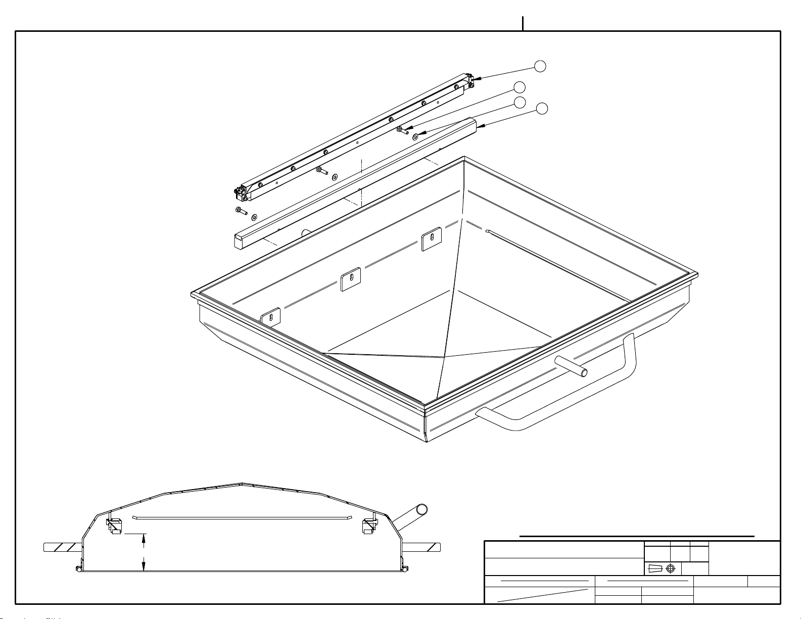
22 005B0453 8" COVER ASSEMBLY 1
23 005B0454 12" COVER ASSEMBLY 1
24 005B0562 SEAL BAR ASS'Y W/SUPPORT (T&B) 4
25 005B0583 MC-40 CONTROL BOARD 1
26 005C0421 UPPER SEAL BAR ASS'Y W/SUPPORT 2
27 005F0561 SEAL BAR ASS'Y W/SUPPORT (ECO) 4
28 009C0136 8" TOP & BOTTOM COVER REWORKED 1
29 009C0137 12" TOP & BOTTOM COVER REWORKED 1
30 033-0014 MC-40 KEYBOARD "FOODPAK" 1
31 033-0015 MC-40 KEYBOARD "SIPROMAC" 1
32 033-0016 MC-40 KEYBOARD "HOLLYMATIC" 1
33 033-0018 MC-40 KEYBOARD "BERKEL" 1
34 033-0019 MC-40 KEYBOARD "BSA" 1
DEPT. TOL.
METRIC
600A
MACHINE ASSEMBLY
CNC
DWG BY
APP. BY
SBU
USINAGE
TOLERIE
SOUDAGE
DATE
DATE
13-12-11
INCH
± 0.1
± 0.004"
±
0.5
±
0.020"
±
0.
5
±
0.020"
N.T.S.
DEPT.
NO.
005D0324
SIPROMAC
ST-GERMAIN DE GRANTHAM
QUEBEC CANADA
M-I
QTY.
1
Page 21

005D0324
2/5
24TOP & BOTTOM SEALING
27ELECTRIC CUT-OFF
29 8" COVER
23 12" COVER
19DOUBLE SEAM BAND
28 8" COVER T&B
29 12" COVER T&B
46
41
43
46
43
40
25 MC-40 CONTROL
31 OR
30 OR
32 OR
33 OR
34 OR
35
38 HEATED BOX OPTION
37 HEATED BOX OPTION
9
MACHINE
PART
ITEM
MAT.
600A
MACHINE ASSEMBLY
CNC
DWG BY
APP. BY
SBU
DEPT. TOL.
USINAGE
TOLERIE
SOUDAGE
DATE
13-12-11
DATE
METRIC
INCH
± 0.1
± 0.004"
±
0.5
±
0.020"
±
0.
5
±
0.020"
N.T.S.
DEPT.
NO.
005D0324
SIPROMAC
ST-GERMAIN DE GRANTHAM
QUEBEC CANADA
M-I
QTY.
1
Page 22
005D0324
3/5
DETAIL A
13 AIR REGULATOR OPTION
DETAIL B
36 T&B ONLY
44
A
B
2 SILENCER (165M³ & +)
4 SILENCER + SOFT AIR (165M³ & +)
3 SOFT AIR (165M³ & +)
1
HOLES TO USE
100M³: 2-5-10-12
165M³: 1-4-7-9
255M³: 2-5-8-11
305M³: 2-5-8-11
6
5
234
10 100M³ PUMP
6 SOFT AIR (100M³)
8 305M³ PUMP
12 255M³ PUMP
7 SILENCER + SOFT AIR (100M³)
5 SILENCER (100M³)
11 165M³ PUMP
-PUMP + AIR REGULATOR INSTALLATION-
MACHINE
10
7
8
9
12
11
PART
ITEM
MAT.
600A
MACHINE ASSEMBLY
CNC
DWG BY
APP. BY
SBU
DEPT. TOL.
USINAGE
TOLERIE
SOUDAGE
DATE
13-12-11
DATE
METRIC
INCH
± 0.1
± 0.004"
±
0.5
±
0.020"
±
0.
5
±
0.020"
N.T.S.
DEPT.
NO.
005D0324
SIPROMAC
ST-GERMAIN DE GRANTHAM
QUEBEC CANADA
M-I
QTY.
1
Page 23
005D0324
4/5
14 WITHOUT AIR REGULATOR
15 WITH AIR REGULATOR
16GAS OPTION
45GAS OPTION
18 4 NOZZLES GAS OPTION
20 3 NOZZLES GAS OPTION
21 4 NOZZLES GAS OPTION
17 3 NOZZLES GAS OPTION
-GAS BAR + BELLOWS VALVE INSTALLATION-
MACHINE
PART
ITEM
MAT.
600A
MACHINE ASSEMBLY
CNC
DWG BY
APP. BY
SBU
DEPT. TOL.
USINAGE
TOLERIE
SOUDAGE
DATE
13-12-11
DATE
METRIC
INCH
± 0.1
± 0.004"
±
0.5
±
0.020"
±
0.
5
±
0.020"
N.T.S.
DEPT.
NO.
005D0324
SIPROMAC
ST-GERMAIN DE GRANTHAM
QUEBEC CANADA
M-I
QTY.
1
Page 24
005D0324
26 TOP & BOTTOM SEALING
39
42
1 DOUBLE SEAM BAND
5/5
85.8
MACHINE
PART
ITEM
MAT.
-UPPER SEAL BAR INSTALLATION-
DEPT. TOL.
METRIC
600A
MACHINE ASSEMBLY
CNC
DWG BY
APP. BY
SBU
USINAGE
TOLERIE
SOUDAGE
DATE
DATE
13-12-11
INCH
± 0.1
± 0.004"
±
0.5
±
0.020"
±
0.
5
±
0.020"
N.T.S.
DEPT.
NO.
005D0324
SIPROMAC
ST-GERMAIN DE GRANTHAM
QUEBEC CANADA
M-I
QTY.
1
Page 25
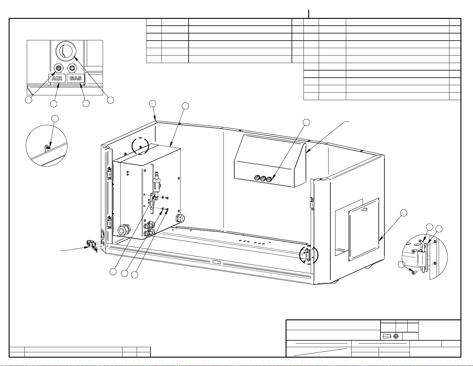
005D0457
ITEM PART # DESCRIPTION QT.
DETAIL B
13
14
15
5
11 056-3010-1 HINGE CONCEALED SS304 - BASE 4
12 056-3010-3 HINGE CONCEALED SS304 - PIN 4
13 102-0551 BULKHEAD 1/4"NPT X 3/8 TUBE QUICK 2
14 127-0040 STICKER ''AIR'' BLUE/WHITE 1'' X 2'' 1
15 127-0041 STICKER ''GAS'' YELLOW/BLACK 1'' X 2'' 1
4
2
ITEM PART # DESCRIPTION QT.
1 004A4090 ACCESS DOOR ASSEMBLY 1
2 004A4098 ELECTRIC BOX ASS'Y 1
3 004A4138 VACUUM SENSOR FILTER 1
4 004E0114 STRUCTURE PRE-ASSEMBLY 1
5 036-0265 GROMMET 1-1/2'' ID X 2-3/8'' OD RUBBER 1
6 036-0409 PRESSE-ETOUPE CD13 3
7 051-01385 SCREW 10-24 x 1/2"FLAT-UND. PHIL S/S 8
8 051-0144 SCREW #10-24 N.C 1/2"PAN PHIL. S/S 8
9 051-0180 BOLT. HEX. 1/4"-20 NC. x 1/2" S/S 2
10 051-0740 WASHER 1/4" FLAT S/S 2
8
DETAIL A
DETAIL B
6
SILICONE ALL AROUND
A
1
12
11
3
C
10
9
7
B
LET. MODIFICATION
004E0114 WAS 004D0114
15-02-24
DATE
SBU
INT.
MACHINE
PART
ITEM
MAT.
600A & 620A
STRUCTURE ASS'Y
CNC
DWG BY
APP. BY
SBU
DEPT. TOL.
USINAGE
TOLERIE
SOUDAGE
DATE
15-02-24
DATE
DETAIL C
METRIC
INCH
± 0.1
± 0.004"
±
0.5
±
0.020"
±
0.
5
±
0.020"
N.T.S.
DEPT.
NO.
005D0457
SIPROMAC
ST-GERMAIN DE GRANTHAM
QUEBEC CANADA
M-(M)-I
QTY.
1
Page 26

005C0583
ITEM PART # DESCRIPTION QT.
1 001B6920 CONTROL PANEL MC-40 1
2 033-0038 MC-40 SENSOR VACUUM 1
3 051-0092 SCREW #4-40 x 1 1/4" FLAT SLT S/S 4
4 051-01081 SCREW 8-32 X 1/2'' TRUSS SLOT SS 6
5 051-0540 NUT #4-40 HEX S/S 8
6 051-0713 WASHER #4 FLAT S/S 4
7 051-0715 WASHER #4 LOCK SS 4
8 058-0120 CPVC SPACER 0.120" x 1/4" x 5/8" 4
9 179-0004 NITRILE 1/2'' X 1/8'' AUTOCOLLANT X
1210mm long
4
6
1
1
9
A
LET. MODIFICATION
SS INSERT
15-02-23
DATE
SBU
INT.
3
8
5
2
7
5
-MC-40 OPTION-
MACHINE
VACUUM
PART
MC-40 CONTROL BOARD
ITEM
MAT.
CNC
3D DWG BY
2D DWG BY
SBU
SBU
DEPT. TOL.
USINAGE
TOLERIE
SOUDAGE
DATE
15-02-23
DATE
15-02-23
METRIC
INCH
± 0.1
± 0.004"
±
0.5
±
0.020"
±
0.
5
±
0.020"
N.T.S.
DEPT.
NO.
005C0583
SIPROMAC
ST-GERMAIN DE GRANTHAM
QUEBEC CANADA
M
QTY.
1
Page 27

005B0454
ITEM PART # DESCRIPTION QT.
1 004B0237 12" COVER PRE-ASS'Y 1
2 179-0020 NEOPRENE SPONGE 1/2" x 14.5' 1
2 UTILISER PERMATEX RUBBER ADHESIVE 169-0010 POUR COLLERUSE PERMATEX RUBBER ADHESIVE 169-0010 TO GLUE
1
POSITION JOINT HERE
POSITIONNER LE JOINT ICI
C
LET.
004B0237 WAS 004A0237
MODIFICATION
14-02-04
DATE
SBU
INT.
MACHINE
PART
ITEM
MAT.
600A
12" COVER ASSEMBLY
CNC
DWG BY
APP. BY
SBU
DEPT. TOL.
USINAGE
TOLERIE
SOUDAGE
DATE
14-02-04
DATE
METRIC
INCH
± 0.1
± 0.004"
±
0.5
±
0.020"
±
0.
5
±
0.020"
N.T.S.
DEPT.
NO.
005B0454
SIPROMAC
ST-GERMAIN DE GRANTHAM
QUEBEC CANADA
M-(M)-I
QTY.
1
Page 28

005B0453
ITEM PART # DESCRIPTION QT.
1 004B0236 8" COVER PRE-ASS'Y 1
2 179-0020 NEOPRENE SPONGE 1/2" x 14.5' 1
2 UTILISER PERMATEX RUBBER ADHESIVE 169-0010 POUR COLLERUSE PERMATEX RUBBER ADHESIVE 169-0010 TO GLUE
1
POSITION JOINT HERE
POSITIONNER LE JOINT ICI
C
LET.
004B0236 WAS 004A0236
MODIFICATION
14-02-04
DATE
SBU
INT.
MACHINE
PART
ITEM
MAT.
600A
8" COVER ASSEMBLY
CNC
DWG BY
APP. BY
SBU
DEPT. TOL.
USINAGE
TOLERIE
SOUDAGE
DATE
14-02-04
DATE
METRIC
INCH
± 0.1
± 0.004"
±
0.5
±
0.020"
±
0.
5
±
0.020"
N.T.S.
DEPT.
NO.
005B0453
SIPROMAC
ST-GERMAIN DE GRANTHAM
QUEBEC CANADA
M-(M)-I
QTY.
1
Page 29

004A4146
ITEM PART # DESCRIPTION QT.
1 004A4095 LEFT REAR ACCESS DOOR PRE-ASSY 1
2 004A4097 RIGHT REAR ACCESS DOOR ASSY 1
3 004A4145 TABLE W/ARM ASSY 1
4 005A0322 FILLER PLATE ASSEMBLY 4
5 005D0457 STRUCTURE ASS'Y 1
6 051-0360 BOLT 3/8"-16nc. X 1" S/S 6
7 051-0622 NUT 3/8"-16nc. NYLON LOCK S/S 6
8 051-0783 WASHER 3/8" FLAT THICK S/S 12
4
4
3
5
6
1
A
LET. MODIFICATION
005D0457 WAS 005C0457
15-04-24
DATE
SBU
INT.
8
A
8
7
DETAIL A
MACHINE
600A
PART
2
ITEM
MAT.
BASE MACHINE ASSEMBLY
CNC
DWG BY
APP. BY
SBU
DEPT. TOL.
USINAGE
TOLERIE
SOUDAGE
DATE
13-11-26
DATE
METRIC
INCH
± 0.1
± 0.004"
±
0.5
±
0.020"
±
0.
5
±
0.020"
N.T.S.
DEPT.
NO.
004A4146
SIPROMAC
ST-GERMAIN DE GRANTHAM
QUEBEC CANADA
M
QTY.
1
Page 30

004A4138
ITEM PART # DESCRIPTION QT.
1 004A4139 VACUUM SENSOR FILTER SUPPORT 1
2 114-2020 FILTER / DRYER ¼"mnpt. X 1/4"t.p. COMP. 1
3 102-0410 MALE CONN.1/4"MNPTx3/8"T.QUICK 2
3
2
LET. MODIFICATION
DATE
INT.
3
1
MACHINE
PART
ITEM
MAT.
VACUUM
VACUUM SENSOR FILTER
CNC
DWG BY
APP. BY
SBU
DEPT. TOL.
USINAGE
TOLERIE
SOUDAGE
DATE
13-11-19
DATE
METRIC
INCH
± 0.1
± 0.004"
±
0.5
±
0.020"
±
0.
5
±
0.020"
N.T.S.
DEPT.
NO.
004A4138
SIPROMAC
ST-GERMAIN DE GRANTHAM
QUEBEC CANADA
M
QTY.
1
Page 31

004A4090
ITEM PART # DESCRIPTION QT.
1 004A4089 ACCESS PANEL PRE-ASSY 1
2 056-2600 SPRING PAWL LATCHE SS KNOB 1
3 051-0071 SCREW 4-40 x 1/4" RND SLOT S/S 2
4 051-0541 NUT # 4-40 NYLON LOCK SS 2
2
3
4
1
LET. MODIFICATION
DATE
INT.
MACHINE
PART
ITEM
MAT.
VACUUM
ACCESS DOOR ASSEMBLY
CNC
DWG BY
APP. BY
SBU
DEPT. TOL.
USINAGE
TOLERIE
SOUDAGE
DATE
13-09-11
DATE
METRIC
INCH
± 0.1
± 0.004"
±
0.5
±
0.020"
±
0.
5
±
0.020"
N.T.S.
DEPT.
NO.
004A4090
SIPROMAC
ST-GERMAIN DE GRANTHAM
QUEBEC CANADA
M
QTY.
1
Page 32

004A4145
ITEM PART # DESCRIPTION QT.
15
16
13
14
11
7
10
10
DETAIL C
9
8
DETAIL B
12
DETAIL D
2
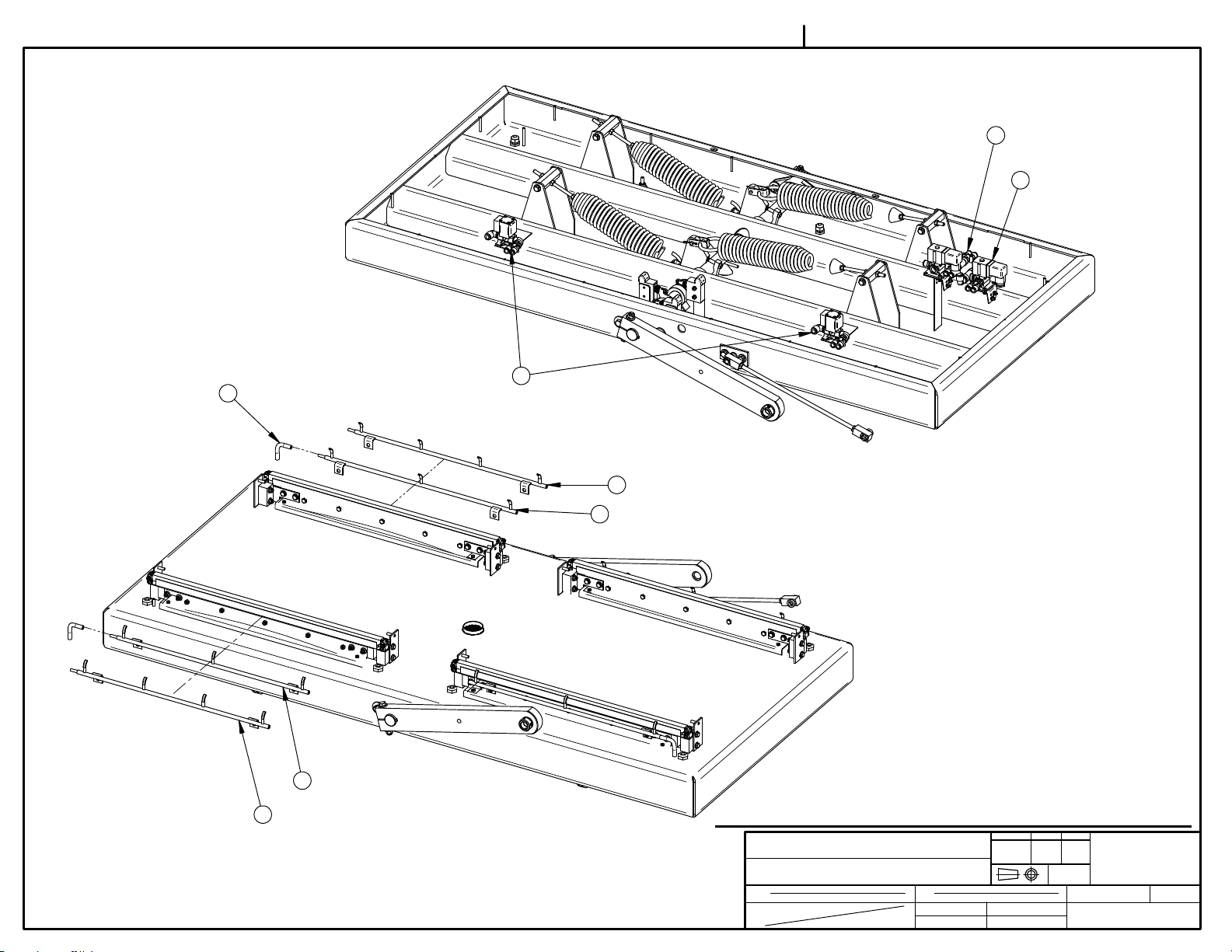
1 004D0122 TABLE ASSEMBLY 1
2 002-0327 RIGHT SEAL BAR GUIDE BLOCK 4
3 002-0326 LEFT SEAL BAR GUIDE BLOCK 4
4 051-0740 WASHER 1/4" FLAT S/S 32
5 051-0250 BOLT ¼"-20nc. X 1½" S/S 16
6 051-0581 NUT 1/4"-20 NYLON LOCK S/S 16
7 004-0280 COVER ARM ASS'Y 2
8 002-0390 COVER ARM COLLAR 2
9 051-0178 SCREW 1/4"-20 x 5/16" SKT SET S/S 4
10 051-0783 WASHER 3/8" FLAT THICK S/S 4
11 051-0422 BOLT 3/8"-16nc. X 3¼" S/S 2
12 051-0622 NUT 3/8"-16nc. NYLON LOCK S/S 2
13 058-0060 NYLON SPACER 1/2IDx3/4ODx1/4" 2
14 058-0050 NYLON SPACER 1/2IDx3/4ODx1/16" 2
15 004A1394 GUIDE ARM PRE-ASS'Y 1
16 056-0331 EXT. RETAINING RING 1/2" S/S 2
17 005A1436 BELLOWS ASSEMBLY 4
18 056-01675 KEY 1/4" SQ. x 1 1/4" ROUNDED END S/S 2
17
C
15
3
6
4
DETAIL A
005A1436 WAS 005-0320 (FIT BAR 620A)
A
LET. MODIFICATION
B
A
7
4
5
14-01-08
SBU
DATE
INT.
D
18
1
MACHINE
PART
ITEM
MAT.
600A
TABLE W/ARM ASSY
CNC
DWG BY
APP. BY
SBU
DEPT. TOL.
USINAGE
TOLERIE
SOUDAGE
DATE
13-11-28
DATE
METRIC
INCH
± 0.1
± 0.004"
±
0.5
±
0.020"
±
0.
5
±
0.020"
N.T.S.
DEPT.
NO.
004A4145
SIPROMAC
ST-GERMAIN DE GRANTHAM
QUEBEC CANADA
M
QTY.
1
Page 33

Page 34

005A1436
ITEM PART # DESCRIPTION QT.
1 008A1996 BELLOWS 1
2 001-0899 BELLOWS CLAMP 4
3 051-0105 SCREW #8-32 x 7/16" TRUSS PHIL S/S 6
4 051-0550 NUT #8-32 SS 6
5 003-0022 BELLOWS CONNECTOR 1
6 051-0620 NUT 3/8"-16 NC S/S 1
7 051-0780 WASHER 3/8" FLAT S/S 1
5
6
7
LET.
2
4
3
MODIFICATION
DATE
1
INT.
APPLY GLUE 169-0013 INSIDE THE BELLOWS
MACHINE
550A, 600A & 620A
PART
BELLOWS ASSEMBLY
ITEM
MAT.
CNC
DWG BY
APP. BY
S.L.
DEPT. TOL.
USINAGE
TOLERIE
SOUDAGE
DATE
13-11-12
DATE
METRIC
INCH
± 0.1
± 0.004"
±
0.5
±
0.020"
±
0.
5
±
0.020"
N.T.S.
DEPT.
NO.
005A1436
SIPROMAC
ST-GERMAIN DE GRANTHAM
QUEBEC CANADA
M
QTY.
2(550) 4
Page 35

ITEM PART # DESCRIPTION QT.
19 051-0720 WASHER #8 FLAT S/S 6
20 051-0560 NUT #8-32 NYLON LOCK S/S 6
21 005-0317 GUIDE ARM AXIS ASS'Y 1
22 051-0783 WASHER 3/8" FLAT THICK S/S 4
23 051-0360 BOLT 3/8"-16nc. X 1" S/S 2
24 051-0620 NUT 3/8"-16 NC S/S 2
25 001A6466 BEARING SPACER 2
26 051-0142 SCREW 8-32 x1-1/2"RND PHIL S/S 6
004D0122
1/2
ITEM PART # DESCRIPTION QT.
1 005D0150 TABLE PRE-ASSEMBLY 1
2 008A1953 SPRING 4
3 002A3941 SPRING ADJ. PIVOT 4
4 051-0600 NUT 5/16" -18 S/S 8
5 002A4002 SPRING ADJ. PIVOT SPACER 8
6 051-0760 WASHER 5/16" FLAT S/S 8
7 051-0300 BOLT 5/16"-18 x 3/4" S/S 8
8 004A3937 SHACKLE ASS'Y 4
9 036-0400 WIRE CONNECT. 3/8'' NPT
8
CD09/O-RING/NUT
10 004A3968 SPRING INSERT ASSEMBLY 4
11 002C0318 CENTRAL SHAFT 1
12 075-1655 2 BOLT FLANGED BEARING 1-1/4" PLASTIC 2
13 051-0428 BOLT 7/16"-14NC x 1-1/2" SS 4
14 001A2954 WASHER 0.468"Ø ID x 1.250"OD x 3.5 8
15 051-0625 NUT 7/16"-14 S/S 4
16 005A1437 MICRO SWITCH COLLAR ASSY 3
17 026-0750 ROLLER PLUNGER SWITCH SPDT 3
18 004B3936 SPRING BLOCK PRE-ASSY 2
PROCÉDURE D'AJUSTEMENT DES
RESSORTS / SPRING ADJUSTMENT
PROCEDURE:
- MESURER LA LONGUEUR INITIALE DES RESSORTS
- INSTALLER LES RESSORTS DE FAÇON LÂCHE ET
SERRER LES ÉCROUS À LA MAIN.
- TENDRE DE FAÇON ÉGALE LES RESSORTS. LA
LONGEUR ÉTIRÉ MOINS LA LONGEUR INITIAL DOIT
ÊTRE ÉGALE POUR CHAQUE RESSORT.
------------
- MEASURE THE INITIAL SPRING LENGTH
- INSTALL THEM LOOSELLY BY THIGHTENING THE
NUT BY HAND
- TENSION SPRING EQUALLY. THE STRECHTED
LENGTH MINUS THE INITIAL LENGTH MUST BE THE
SAME ON EACH SPRING.
H
LET. MODIFICATION
005D0150 WAS 005C0150
13-12-02
DATE
SBU
INT.
MACHINE
PART
ITEM
MAT.
600A
TABLE ASSEMBLY
CNC
DWG BY
APP. BY
SBU
DEPT. TOL.
USINAGE
TOLERIE
SOUDAGE
DATE
13-12-02
DATE
METRIC
INCH
± 0.1
± 0.004"
±
0.5
±
0.020"
±
0.
5
±
0.020"
N.T.S.
DEPT.
NO.
004D0122
SIPROMAC
ST-GERMAIN DE GRANTHAM
QUEBEC CANADA
M-(M)
QTY.
1
Page 36

004D0122
22
2/2
24
D
18
8
11
2
23
21
22
DETAIL A
C
3
5
9
B
16
6
7
DETAIL D
14
13
4
10
35.5
REAR
AJUSTEMENT DE L'ARBRE / SHAFT ADJUSTMENT:
- UTILISER LES CALES POUR POSITIONNER L'ARBRE
-----------
- USE BLOC TO SPACE THE SHAFT ACCORDINGLY
A
34
FRONT
DETAIL B
20
DETAIL C
MACHINE
26
PART
17
19
ITEM
MAT.
600A
TABLE ASSEMBLY
CNC
DWG BY
APP. BY
SBU
15
DEPT. TOL.
USINAGE
TOLERIE
SOUDAGE
DATE
13-12-02
DATE
14
METRIC
± 0.1
±
0.5
±
0.
12
INCH
± 0.004"
±
0.020"
5
±
0.020"
N.T.S.
DEPT.
NO.
004D0122
25
SIPROMAC
ST-GERMAIN DE GRANTHAM
QUEBEC CANADA
M-(M)
QTY.
1
Page 37

004B3936
ITEM PART # DESCRIPTION QT.
1 002B4058 SPRING BLOCK 1
2 075-0015 BUSHING PL.5/16" x 1/2" x 1/2" 2
3 002B3939 UPPER SPRING BLOCK 1
4 051-0312 S/S BOLT 5/16" - 18NC. 2 1/4" 2
1
2 PRESS FITSERRAGE
B
A
AJOUTER 620A
REDESSINÉ
LET. MODIFICATION
13-01-23
13-01-15
DATE
J.G.
J.G.
INT.
3
4
QTY.
LISTE
2
2
QTY
MACHINE
VACCUM
PART
SPRING BLOCK PRE-ASSY
ITEM
MAT.
CNC
DWG BY
APP. BY
J.G.
DEPT. TOL.
USINAGE
TOLERIE
SOUDAGE
DATE
13-01-15
DATE
METRIC
INCH
± 0.1
± 0.004"
±
0.5
±
0.020"
±
0.
5
±
0.020"
N.T.S.
DEPT.
NO.
004B3936
620A
600A
MACHINE
SIPROMAC
ST-GERMAIN DE GRANTHAM
QUEBEC CANADA
U-(M)
Page 38

004A3968
ITEM PART # DESCRIPTION QT.
1 002A3989 SPRING ADJUSTMENT ROD 1
2 051-0600 NUT 5/16" -18 S/S 2
3 002B3940 SPRING INSERT 1
2
3
2
1
A
AJOUTER 620A
LET. MODIFICATION
13-01-23
DATE
J.G.
INT.
MACHINE
600A & 620A
PART
SPRING INSERT ASSEMBLY
ITEM
MAT.
CNC
DWG BY
APP. BY
J.G.
DEPT. TOL.
USINAGE
TOLERIE
SOUDAGE
DATE
13-01-15
DATE
METRIC
INCH
± 0.1
± 0.004"
±
0.5
±
0.020"
±
0.
5
±
0.020"
N.T.S.
DEPT.
NO.
004A3968
620A
600A
MACHINE
QTY
SIPROMAC
ST-GERMAIN DE GRANTHAM
QUEBEC CANADA
M-(M)
QTY.
LISTE
4
4
Page 39

004A3937
ITEM PART # DESCRIPTION QT.
1 004A3935 SHACKLE PRE-ASS'Y 1
2 001A6269 SHACKLE PLATE 1
3 056-0118 COTTER PIN 3/32" x 1" S/S 1
2
1
LET. MODIFICATION
DATE
INT.
MACHINE
PART
ITEM
MAT.
3
VACUUM
SHACKLE ASS'Y
CNC
DWG BY
APP. BY
J.G.
DEPT. TOL.
USINAGE
TOLERIE
SOUDAGE
DATE
12-11-06
DATE
METRIC
INCH
± 0.1
± 0.004"
±
0.5
±
0.020"
±
0.
5
±
0.020"
N.T.S.
DEPT.
NO.
004A3937
600A
MACHINE
QTY
SIPROMAC
ST-GERMAIN DE GRANTHAM
QUEBEC CANADA
M-(M)
QTY.
LISTE
4
Page 40

ITEM PART # DESCRIPTION QT.
11 051-0580 NUT 1/4"-20 S/S 4
12 051-0210 BOLT ¼"-20nc. X 1" S/S 4
13 051-0581 NUT 1/4"-20 NYLON LOCK S/S 4
14 051-0139 SCREW 10-24 x 1/2" FLAT PHIL S/S 4
15 028-0105 GROUND BARRIER (6 HOLES) 1
16 051-0128 SCREW 10-24 x 3/8'' TRUSS PHIL S/S 4
1
3
2
14
004A4098
ITEM PART # DESCRIPTION QT.
1 004A4099 E-BOX PRE-ASSY 1
2 056-3010-1 HINGE CONCEALED SS304 - BASE 2
3 056-3010-3 HINGE CONCEALED SS304 - PIN 2
4 004A4102 E-BOX FALSE BOTTOM 1
5 036-0430 PRESSE-ÉTOUPE CD29 1
6 036-0409 PRESSE-ETOUPE CD13 3
7 004A4100 E-BOX DOOR ASSEMBLY 1
8 036-0420 PRESSE-ÉTOUPE CD21 2
9 036-0440 PRESSE-ÉTOUPE CD36 1
10 051-0600 NUT 5/16" -18 S/S 4
16
PUMP
4
5
16
8
SEAL BAR
10
11
12
A
TOP BOTTOM OPTION
VALVES
MC-40
6
DETAIL A
9
NOTE:
15
- 026-3161 - DISCONNECT SWITCH SHAFT: COUPER À
134 MM DE LONG.
LET. MODIFICATION
7
DATE
INT.
13
MACHINE
PART
ITEM
MAT.
VACUUM
ELECTRIC BOX ASS'Y
CNC
DWG BY
APP. BY
SBU
DEPT. TOL.
USINAGE
TOLERIE
SOUDAGE
DATE
13-09-23
DATE
METRIC
INCH
± 0.1
± 0.004"
±
0.5
±
0.020"
±
0.
5
±
0.020"
N.T.S.
DEPT.
NO.
004A4098
SIPROMAC
ST-GERMAIN DE GRANTHAM
QUEBEC CANADA
M
QTY.
1
Page 41

004A4100
ITEM PART # DESCRIPTION QT.
1 004A4101 E-BOX DOOR PRE-ASSY 1
2 056-2612 CAM LOCK QUARTER TURN SS304 1
3 179-0026 D-SHAPED RUBBER SEAL 1683mm LONG 1
4 026-3160 HANDLE RED/YELLOW NEMA 4X,
COMPACT, PADLOCKABLE
4
5 127-0100 STICKER ELEC.HAZARD ISO 2-1/2''
TRIANGLE
5 CENTER WITH HANDLE
16.4
1
1
LET. MODIFICATION
434
2
418
3
1
DATE
INT.
MACHINE
PART
ITEM
MAT.
VACUUM
E-BOX DOOR ASSEMBLY
CNC
DWG BY
APP. BY
SBU
DEPT. TOL.
USINAGE
TOLERIE
SOUDAGE
DATE
13-09-17
DATE
METRIC
INCH
± 0.1
± 0.004"
±
0.5
±
0.020"
±
0.
5
±
0.020"
N.T.S.
DEPT.
NO.
004A4100
SIPROMAC
ST-GERMAIN DE GRANTHAM
QUEBEC CANADA
M
QTY.
1
Page 42

004A4097
ITEM PART # DESCRIPTION QT.
1 004A4096 RIGHT REAR ACCESS DOOR PRE-ASSY 1
2 056-2600 SPRING PAWL LATCHE SS KNOB 2
3 051-0071 SCREW 4-40 x 1/4" RND SLOT S/S 4
4 051-0541 NUT # 4-40 NYLON LOCK SS 4
A
2
4
1
3
LET. MODIFICATION
DATE
INT.
MACHINE
600A & 620A
PART
RIGHT REAR ACCESS DOOR ASSY
ITEM
MAT.
CNC
DWG BY
APP. BY
SBU
DETAIL A
DEPT. TOL.
METRIC
USINAGE
TOLERIE
SOUDAGE
DATE
DATE
13-09-16
INCH
± 0.1
± 0.004"
±
0.5
±
0.020"
±
0.
5
±
0.020"
N.T.S.
DEPT.
NO.
004A4097
SIPROMAC
ST-GERMAIN DE GRANTHAM
QUEBEC CANADA
M
QTY.
1
Page 43

005A0560
ITEM PART # DESCRIPTION QT.
1 005A0418 SEAL BAR PRE-ASS'Y 1
2 051-0251 CAP. HEX. SKT BOLT 1/4"-20 NC. x 1 1/2" 4
3 051-0581 NUT 1/4"-20 NYLON LOCK S/S 9
4 051-0230 HEX BOLT 1/4-20 x 1 1/4" SS 5
5 051-0250 BOLT ¼"-20nc. X 1½" S/S 4
6 051-0740 WASHER 1/4" FLAT S/S 8
10
9
1
6
5
4
7 001-1591 EXTERIOR BELLOWS COVER 1
8 002A4162 SEAL BAR SUPPORT 1
9 001-1958 INTERIOR BELLOWS COVER 1
10 001-0269 SEAL BAR GUIDE 2
7
6
3
VUE A
600A ADDED, 002A4162 WAS 002-0510
C
B
LET.
REDRAWN
MODIFICATION
14-05-27
05-09-12
DATE
SBU
M.A.
INT.
25.5
REF.
VUE A
8
2
MACHINE
PART
ITEM
MAT.
600A & 620A
SEAL BAR ASS'Y W/SUPPORT
31.5
REF.
THIS SIDE OF SEAL BAR
TO FIT FLUSH W/SUPPORT
-TWIN SEAL OPTION-
DEPT. TOL.
METRIC
± 0.1
±
±
0.5
0.
5
INCH
± 0.004"
±
0.020"
±
0.020"
N.T.S.
DEPT.
NO.
CNC
DWG BY
APP. BY
M.A.L.
USINAGE
TOLERIE
SOUDAGE
DATE
DATE
05-09-12
SIPROMAC
ST-GERMAIN DE GRANTHAM
QUEBEC CANADA
M-(M)-I
QTY.
4
005A0560
Page 44

005A0418
ITEM PART # DESCRIPTION QT.
1 002A0400 SEAL BAR 1
2 039-0268 DOUBLE SEAM BAND (8MM) (2.4) 1
3 176-0200 TEFLON TAPE 5MIL (0.81) 1
4 056-1401 3/8"SET SCREW BANDING BUCKLE S/S 2
5 052-0393 SCREW 1/4-28x3/16"SKT SET OVAL POINT
ZINC
6 051-0100 SCREW 8-32 X 3/8" PAN PHIL S/S 2
7 051-0550 NUT #8-32 SS 4
8 027-0400 CONNECTOR ADAPTOR 2
9 001A2742 8mm ELEMENT BINDER 2
10 051-0146 SCREW 10-24 X 1" PAN PHIL S/S 2
11 051-0572 NUT #10-24 NYLON LOCK S/S 2
12 171-0180 TAPE CLEAR SUPER BOND 3/4" 641.5mm
(0.019)
13 077-0095 SPRING C 0360-059-1250 S/S 2
3
2
1
13
2
2
H
G
F
E
LET.
MODIF. A-453 AJOUTER 077-0095
600A ADDED
ADDED 052-0393
REDRAWN
MODIFICATION
14-05-27
10-06-01
06-04-19
05-09-12
DATE
SBU
J.G.
M.A.
M.A.
INT.
VOIR DÉTAIL A
-DÉTAIL A-
10
7
12
8
7
11
6
5
9PERMETTRE DE BOUGER LIBREMENT ALLOW TO MOVE FREELY
4 INSTALL AGAINST NOTCH OF ITEM #9INSTALLER CONTRE L'ENCOCHE DE L'ITEM #9
-TWIN SEAL OPTION-
MACHINE
PART
ITEM
MAT.
600A & 620A
SEAL BAR PRE-ASS'Y
CNC
DWG BY
APP. BY
M.A.L.
DEPT. TOL.
USINAGE
TOLERIE
SOUDAGE
DATE
05-09-12
DATE
METRIC
INCH
± 0.1
± 0.004"
±
0.5
±
0.020"
±
0.
5
±
0.020"
N.T.S.
DEPT.
NO.
005A0418
SIPROMAC
ST-GERMAIN DE GRANTHAM
QUEBEC CANADA
M-(M)-I
QTY.
4
Page 45

005F0561
ITEM PART # DESCRIPTION QT.
5 001-0269 SEAL BAR GUIDE 2
3 001-1591 EXTERIOR BELLOWS COVER 1
4 001-1958 INTERIOR BELLOWS COVER 1
2 002A4191 SEAL BAR SUPPORT (ECO) 1
1 005F0419 SEAL BAR PRE-ASS'Y 1
8 051-0230 HEX BOLT 1/4-20 x 1 1/4" SS 5
7 051-0250 BOLT ¼"-20nc. X 1½" S/S 4
10 051-0251 CAP. HEX. SKT BOLT 1/4"-20 NC. x 1 1/2" 4
9 051-0581 NUT 1/4"-20 NYLON LOCK S/S 9
6 051-0740 WASHER 1/4" FLAT S/S 8
8
7
H
G
LET.
9
3
600A ADDED
005D0153 WAS 005C0153
MODIFICATION
-END VIEW-
14-05-27
SBU
13-11-06
SBU
DATE
INT.
10
3
-BAG CUT OPTION-
MACHINE
PART
ITEM
MAT.
600A & 620A
SEAL BAR ASS'Y W/SUPPORT (ECO)
6
5
4
1
2
CNC
DWG BY
APP. BY
Y.F.
DEPT. TOL.
USINAGE
TOLERIE
SOUDAGE
DATE
14-02-19
DATE
METRIC
INCH
± 0.1
± 0.004"
±
0.5
±
0.020"
±
0.
5
±
0.020"
N.T.S.
DEPT.
NO.
005F0561
620A
600A
MACHINE
SIPROMAC
ST-GERMAIN DE GRANTHAM
QUEBEC CANADA
M-I
QTY.
4
4
QTY
4
Page 46

005F0419
ITEM PART # DESCRIPTION QT.
1 002A4172 BANDING BUCKLE 4
2 002A4190 SEAL BAR (ECO) 1
3 005A1443 ELEMENT BINDER RIGHT ECO 2
4 005A1444 ELEMENT BINDER LEFT ECO 2
5 027-0400 CONNECTOR ADAPTOR 6
6 039-02115 ROUND CUT-OFF ELEMENT 0.9MM 1
7 039-0222 TAPERED BAND 3MM X 0.3MM 1
8 051-0154 SCREW 10-24 x 1-1/4"PAN SLOT S/S 2
9 051-01752 SET SCREW 10-32 SS 3/16" 2
10 051-01752 SET SCREW 10-32 SS 3/16" 2
11 051-0550 NUT #8-32 SS 8
-DÉTAIL A-
7
15
6
12 077-0014 SPRING C0240-040-1250 SS COMP. 4
13 171-0180 TAPE CLEAR SUPER BOND 3/4" 663.5mm (0.021) 2
14 176-0200 TEFLON TAPE 5MIL 1
15 176-0203 TEFLON TAPE UNCOATED ZONE 5MIL 1
A
LET.
600A ADDED
MODIFICATION
14-05-27
DATE
2
SBU
INT.
3 ALLOW TO MOVE FREELYPERMETTRE DE BOUGER LIBREMENT
14
12
9
13
11
8
5
1
-BAG CUT (ECO) -
MACHINE
PART
ITEM
MAT.
600A & 620A
SEAL BAR PRE-ASS'Y
CNC
DWG BY
APP. BY
Y.F.
DEPT. TOL.
USINAGE
TOLERIE
SOUDAGE
DATE
14-02-19
DATE
METRIC
INCH
± 0.1
± 0.004"
±
0.5
±
0.020"
±
0.
5
±
0.020"
N.T.S.
DEPT.
NO.
005F0419
620A
600A
MACHINE
QTY
SIPROMAC
ST-GERMAIN DE GRANTHAM
QUEBEC CANADA
M-I
QTY.
LISTE
4
4
Page 47

005B0562
ITEM PART # DESCRIPTION QT.
1 005B0420 SEAL BAR PRE-ASS'Y 1
2 051-0256 BOLT 1/4"-20nc. X 1 3/4" CAP SKT S/S 4
3 051-0581 NUT 1/4"-20 NYLON LOCK S/S 9
4 051-0230 HEX BOLT 1/4-20 x 1 1/4" SS 5
5 051-0250 BOLT ¼"-20nc. X 1½" S/S 4
6 051-0740 WASHER 1/4" FLAT S/S 8
10
9
1
6
5
4
7 001-1591 EXTERIOR BELLOWS COVER 1
8 002A4162 SEAL BAR SUPPORT 1
9 001-1958 INTERIOR BELLOWS COVER 1
10 001-0269 SEAL BAR GUIDE 2
7
6
3
VUE A
600A ADDED, 002A4162 WAS 002-0510
C
B
LET.
005B0420 WAS 005A0420
MODIFICATION
14-05-27
13-09-25
DATE
SBU
SBU
INT.
25.5
REF.
VUE A
8
2
MACHINE
PART
ITEM
MAT.
600A & 620A
SEAL BAR ASS'Y W/SUPPORT (T&B)
CNC
DWG BY
APP. BY
31.5
REF.
THIS SIDE OF SEAL BAR
TO FIT FLUSH W/SUPPORT
-TOP & BOTTOM
SEALING OPTION-
DEPT. TOL.
METRIC
INCH
± 0.1
± 0.004"
±
0.5
±
0.020"
±
0.
5
±
0.020"
N.T.S.
DEPT.
NO.
005B0562
ST-GERMAIN DE GRANTHAM
QUEBEC CANADA
SBU
USINAGE
TOLERIE
SOUDAGE
DATE
DATE
13-09-25
SIPROMAC
M-I
QTY.
4
Page 48

005B0420
ITEM PART # DESCRIPTION QT.
1 002A4147 SEAL BAR 1
2 001-2666 ELEMENT BINDER 2
3 051-0146 SCREW 10-24 X 1" PAN PHIL S/S 7
4 051-0572 NUT #10-24 NYLON LOCK S/S 7
5 051-0100 SCREW 8-32 X 3/8" PAN PHIL S/S 2
6 051-0550 NUT #8-32 SS 4
3
14
12
7 027-0400 CONNECTOR ADAPTOR 2
8 179-0003 SILICONE 2mm x 15mm ADHESIVE 664mm
(0.664)
9 176-0220 TEFLON TAPE, PRESS SENSITIVE 2" (0.081) 1
10 039-0220 BI-ACTIVE SEALING ELEMENT 700mm (0.07) 1
11 056-1400 1/4"SET SCREW BANDING BUCKLE S/S 2
12 176-0203 TEFLON TAPE, 5MIL UNCOATED ZONE
663.5mm (0.066)
13 077-0095 SPRING C 0360-059-1250 S/S 2
14 001A6582 TEFLON HOLD DOWN PLATE 2
10
9
1
1
H
G
LET.
13
6
7
6
4
600A ADDED
AJOUT TEFLON HOLDER
MODIFICATION
2PERMETTRE DE BOUGER LIBREMENT ALLOW TO MOVE FREELY
5
11 INSTALL AGAINST NOTCH OF ITEM #2INSTALLER CONTRE L'ENCOCHE DE L'ITEM #2
14-05-27
SBU
13-09-25
SBU
DATE
INT.
14
4
3
11
DETAIL B
1
VOIR DÉTAIL A
MACHINE
PART
ITEM
MAT.
8
B
600A & 620A
SEAL BAR PRE-ASS'Y
CNC
DWG BY
APP. BY
-DÉTAIL A-
-TOP & BOTTOM
SEALING OPTION-
DEPT. TOL.
METRIC
INCH
± 0.1
± 0.004"
±
0.5
±
0.020"
±
0.
5
±
0.020"
N.T.S.
DEPT.
NO.
005B0420
ST-GERMAIN DE GRANTHAM
QUEBEC CANADA
SBU
USINAGE
TOLERIE
SOUDAGE
DATE
DATE
13-09-25
SIPROMAC
M-I
QTY.
4
Page 49

CE COTÉ DE LA BARRE DOIT ÊTRE ÉGAL
AU SUPPORT
THIS SIDE OF SEAL BAR TO FIT FLUSH
WITH SUPPORT
16
005C0421
ITEM PART # DESCRIPTION QT.
1 002A0536 UPPER SEAL BAR SUPPORT 1
2 002C0401 UPPER SEAL BAR 1
3 051-0232 SCREW 1/4-20x 1-1/4"SKT CAP SS 8
4 001-2666 ELEMENT BINDER 2
5 051-0146 SCREW 10-24 X 1" PAN PHIL S/S 8
6 051-0572 NUT #10-24 NYLON LOCK S/S 8
7 051-0104 SCREW 8-32 x 3/8" RND PHIL S/S 2
3
1
6
10
11
12
15
8 051-0550 NUT #8-32 SS 4
9 027-0400 CONNECTOR ADAPTOR 2
10 179-0003 SILICONE 2mm x 15mm ADHESIVE 733mm
(0.73)
11 176-0220 TEFLON TAPE,PRESS.SENSITIVE 2" 733mm
(0.089)
12 039-0220 BI-ACTIVE SEALING ELEMENT (6mm) 776mm
(0.078)
13 056-1400 1/4"SET SCREW BANDING BUCKLE S/S 2
14 077-0095 SPRING C 0360-059-1250 S/S 2
15 176-0203 TEFLON TAPE, 5MIL UNCOATED ZONE
733mm (0.089)
16 001A6583 UPPER TEFLON HOLDER 2
5
14
2
6
1
1
1
1
J
H
LET.
A
600A ADDED
AJOUT TEFLON HOLDER
MODIFICATION
14-05-27
13-09-25
DATE
SBU
SBU
INT.
DETAIL A
16
5
13 INSTALL AGAINST NOTCH OF ITM #4INSTALLER CONTRE ENCOCHE DE L'ITEM #4
-TOP & BOTTOM SEALING OPTION-
MACHINE
PART
ITEM
MAT.
600A & 620A
UPPER SEAL BAR ASS'Y W/SUPPORT
13
7
8
8
9
4 ALLOW TO MOVE FREELYPERMETTRE DE BOUGER LIBREMENT
DEPT. TOL.
METRIC
INCH
± 0.1
± 0.004"
±
0.5
±
0.020"
±
0.
5
±
0.020"
N.T.S.
DEPT.
NO.
005C0421
SIPROMAC
ST-GERMAIN DE GRANTHAM
QUEBEC CANADA
M-(M)-I
QTY.
2
CNC
DWG BY
APP. BY
SBU
USINAGE
TOLERIE
SOUDAGE
DATE
DATE
13-09-25
Page 50

005A1536
ITEM PART # DESCRIPTION QT.
1 004A4247 SEAL BAR SUPPORT (SS) 1
2 005A0418 SEAL BAR PRE-ASS'Y 1
3 051-0210 BOLT ¼"-20nc. X 1" S/S 4
4 051-0740 WASHER 1/4" FLAT S/S 4
2
1
COSSE DE CE CÔTÉ
CONNECTOR ON THIS SIDE
LET. MODIFICATION
DATE
INT.
3
4
OPTION - TWIN SEAL / STAINLESS BAR
MACHINE
600A & 620A
PART
SEAL BAR ASSY W/ SS SUPPORT (TWIN SEAL)
ITEM
MAT.
CNC
3D DWG BY
2D DWG BY
SBU
SBU
DEPT. TOL.
USINAGE
TOLERIE
SOUDAGE
DATE
14-10-09
DATE
14-10-09
METRIC
INCH
± 0.1
± 0.004"
±
0.5
±
0.020"
±
0.
5
±
0.020"
N.T.S.
DEPT.
NO.
005A1536
SIPROMAC
ST-GERMAIN DE GRANTHAM
QUEBEC CANADA
M
QTY.
4
Page 51

004A1125
ITEM PART # DESCRIPTION QT.
1 002A2124 UPPER SEAL BAR SUPPORT 1
2 008-0402 UPPER SEAL BAR RUBBER 1
3 171-0180 TAPE CLEAR SUPER BOND 3/4" (0.024) 2
4 176-0200 TEFLON TAPE,PRESS.SENSITIVE 2" 683mm (0.08) 1
3
D
C
MODIF. #A-0444 / AJOUTER TWIN / ÉTAIT 005A0572
B
REDESSINÉ VOIR AUSSI 004A2559 & 004A2560
A
LET.
600A ADDED
AJOUTER ITEM # 3 ET 4
MODIFICATION
14-05-27
14-03-31
10-10-01
08-04-30
DATE
SBU
S.L.
J.G.
J.G.
INT.
-TWIN SEAL-
MACHINE
PART
UPPER SEAL BAR ASSEMBLY (E.C.O.) & (TWIN)
ITEM
MAT.
600A & 620A
CNC
DWG BY
APP. BY
J.G.
DEPT. TOL.
USINAGE
TOLERIE
SOUDAGE
DATE
08-04-30
DATE
1
2
METRIC
INCH
± 0.1
± 0.004"
±
0.5
±
0.020"
±
0.
5
±
0.020"
N.T.S.
DEPT.
NO.
004A1125
4
SIPROMAC
ST-GERMAIN DE GRANTHAM
QUEBEC CANADA
M-I
QTY.
2
Page 52

004B1471
ITEM PART # DESCRIPTION QT.
9 105-0258 EAR CLAMP 2" S/S 2
10 104-0125 HOSE 1-1/2'' ID VACUUM POLYWIRE (1720mm) 1
11 105-0250 EAR CLAMP 1-1/2" S/S 1
12 105-0110 SCREW CLAMPS 1-1/16'' TO 2'' ALL S/S 1
13 125-0080 BUSCH RA-0255 230-460V/3PH/60HZ 1
14 004A4082 BELLOWS ELBOW CONNECTOR ASSY 1
15 100-1250 STRAIGHT 2"MNPT X 2" HOSE BARB SS 1
16 125-0085 BUSCH RA-0255 575V/3PH/60HZ 1
TO TABLE
VACUUM INLET
3
9
12
10
9
15 14
2
ITEM PART # DESCRIPTION QT.
1 001B6563 PUMP SUPPORT 2
2 004A0863 VACUUM/ATMOSPHERE VALVE ASSY 1
3 104-0150 HOSE 2'' ID VACUUM POLYWIRE (554mm) 1
4 051-0783 WASHER 3/8" FLAT THICK S/S 20
5 051-0360 BOLT 3/8"-16nc. X 1" S/S 10
6 051-0622 NUT 3/8"-16nc. NYLON LOCK S/S 10
7 051-0780 WASHER 3/8" FLAT S/S 4
8 051-09931 BOLT M10 X 20MM HEX SS 4
5
7
6
SMALL HOLES MUST
BE ON OIL RESERVOIR SIDE
A
LET. MODIFICATION
001B6563 WAS 001A6563
15
13 OR
14
16
22°
11
5
1
4
4
6
14-05-28
DATE
8USE BLUE LOCTITE
SBU
INT.
-OPTION - 255M³ PUMP
MACHINE
PART
ITEM
MAT.
600A & 620A
PUMP "BUSCH" 255 M³
CNC
DWG BY
APP. BY
SBU
DEPT. TOL.
USINAGE
TOLERIE
SOUDAGE
DATE
13-09-18
DATE
METRIC
INCH
± 0.1
± 0.004"
±
0.5
±
0.020"
±
0.
5
±
0.020"
N.T.S.
DEPT.
NO.
004B1471
SIPROMAC
ST-GERMAIN DE GRANTHAM
QUEBEC CANADA
M-I
QTY.
1
Page 53

ITEM PART # DESCRIPTION QT.
9 051-09931 BOLT M10 X 20MM HEX SS 4
10 051-0360 BOLT 3/8"-16nc. X 1" S/S 10
11 051-0622 NUT 3/8"-16nc. NYLON LOCK S/S 10
12 051-0780 WASHER 3/8" FLAT S/S 4
13 125-0070 BUSCH RA-0165 230-460V/3PH/60HZ 1
14 004A4082 BELLOWS ELBOW CONNECTOR ASSY 1
15 100-1250 STRAIGHT 2"MNPT X 2" HOSE BARB SS 1
16 125-0075 BUSCH RA-0165 575V/3PH/60HZ 1
3
TO TABLE
VACUUM INLET
6
7
4
15
14
004B1469
ITEM PART # DESCRIPTION QT.
1 001B6563 PUMP SUPPORT 2
2 004A0863 VACUUM/ATMOSPHERE VALVE ASSY 1
3 104-0125 HOSE 1-1/2'' ID VACUUM POLYWIRE (1720mm) 1
4 105-0110 SCREW CLAMPS 1-1/16'' TO 2'' ALL S/S 1
5 105-0250 EAR CLAMP 1-1/2" S/S 1
6 104-0150 HOSE 2'' ID VACUUM POLYWIRE (570mm) 1
7 105-0258 EAR CLAMP 2" S/S 2
8 051-0783 WASHER 3/8" FLAT THICK S/S 20
2
10
12
12
11
5
SMALL HOLES MUST
BE ON OIL RESERVOIR SIDE
13 OR
16
15
14
15°
10
8
A
001B6563 WAS 001A6563
LET. MODIFICATION
8
-OPTION - 165M³ PUMP
11
14-05-28
DATE
SBU
INT.
9 USE BLUE LOCTITE
MACHINE
600A & 620A
PART
PUMP "BUSCH" 165 M³ ASSEMBLY
ITEM
MAT.
CNC
DWG BY
APP. BY
SBU
DEPT. TOL.
USINAGE
TOLERIE
SOUDAGE
DATE
13-09-18
DATE
METRIC
INCH
± 0.1
± 0.004"
±
0.5
±
0.020"
±
0.
5
±
0.020"
N.T.S.
DEPT.
NO.
004B1469
SIPROMAC
ST-GERMAIN DE GRANTHAM
QUEBEC CANADA
M-I
QTY.
1
Page 54

004B1468
9
TO TABLE
VACUUM INLET
7
8
13
ITEM PART # DESCRIPTION QT.
1 001B6563 PUMP SUPPORT 2
2 051-0762 WASHER 5/16" THICK FLAT S/S 4
3 051-0980 BOLT M8 x 20 S/S 4
4 051-0783 WASHER 3/8" FLAT THICK S/S 16
5 051-0360 BOLT 3/8"-16nc. X 1" S/S 8
6 051-0622 NUT 3/8"-16nc. NYLON LOCK S/S 8
7 104-0125 HOSE 1-1/2'' ID VACUUM POLYWIRE (810mm) 1
8 105-0250 EAR CLAMP 1-1/2" S/S 1
9 105-0110 SCREW CLAMPS 1-1/16'' TO 2'' ALL S/S 1
10 125-0060 BUSCH RA-0100 230-460V/3PH/60HZ 1
11 125-0062 BUSCH RA-0100 575V/3PH/60HZ 1
12 125-0064 BUSCH RA-0100 220V/1PH/60HZ 1
13 004B1404 VACUUM / ATMOSPHERE VALVE ASSY. 1
10 OR
11 OR
12
5
A
LET. MODIFICATION
001B6563 WAS 001A6563
SMALL HOLE MUST BE
ON OIL RESERVOIR SIDE
0
DATE
I
INT.
2
3 USE BLUE LOCTITE
15°
1
4
6
-OPTION - 100M³ PUMP
MACHINE
PART
ITEM
MAT.
600A & 620A
PUMP "BUSCH" 100 M³ ASSEMBLY
CNC
DWG BY
APP. BY
SBU
DEPT. TOL.
USINAGE
TOLERIE
SOUDAGE
DATE
13-09-19
DATE
METRIC
INCH
± 0.1
± 0.004"
±
0.5
±
0.020"
±
0.
5
±
0.020"
N.T.S.
DEPT.
NO.
004B1468
SIPROMAC
ST-GERMAIN DE GRANTHAM
QUEBEC CANADA
M-I
QTY.
1
Page 55

ITEM PART # DESCRIPTION QT.
9 105-0258 EAR CLAMP 2" S/S 2
10 104-0125 HOSE 1-1/2'' ID VACUUM POLYWIRE (1720mm) 1
11 105-0250 EAR CLAMP 1-1/2" S/S 1
12 105-0110 SCREW CLAMPS 1-1/16'' TO 2'' ALL S/S 1
13 125-0087 BUSCH RA-0305 230-460V/3PH/60HZ 1
14 004A4082 BELLOWS ELBOW CONNECTOR ASSY 1
15 100-1250 STRAIGHT 2"MNPT X 2" HOSE BARB SS 1
16 125-0088 BUSCH RA-0305 575V/3PH/60HZ 1
004A4141
ITEM PART # DESCRIPTION QT.
1 001B6563 PUMP SUPPORT 2
2 004A0863 VACUUM/ATMOSPHERE VALVE ASSY 1
3 104-0150 HOSE 2'' ID VACUUM POLYWIRE (554mm) 1
4 051-0783 WASHER 3/8" FLAT THICK S/S 20
5 051-0360 BOLT 3/8"-16nc. X 1" S/S 10
6 051-0622 NUT 3/8"-16nc. NYLON LOCK S/S 10
7 051-0780 WASHER 3/8" FLAT S/S 4
8 051-09931 BOLT M10 X 20MM HEX SS 4
TO TABLE
VACUUM INLET
3
9
10
12
9
15 14
2
15
13 OR
14
16
22°
11
5
7
6
SMALL HOLES MUST
BE ON OIL RESERVOIR SIDE
A
LET. MODIFICATION
001B6563 WAS 001A6563
5
1
4
4
6
8USE BLUE LOCTITE
14-05-28
SBU
DATE
INT.
-OPTION - 305M³ PUMP
MACHINE
PART
ITEM
MAT.
600A & 620A
PUMP "BUSCH" 305 M³
CNC
DWG BY
APP. BY
SBU
DEPT. TOL.
USINAGE
TOLERIE
SOUDAGE
DATE
13-11-21
DATE
METRIC
INCH
± 0.1
± 0.004"
±
0.5
±
0.020"
±
0.
5
±
0.020"
N.T.S.
DEPT.
NO.
004A4141
SIPROMAC
ST-GERMAIN DE GRANTHAM
QUEBEC CANADA
M-I
QTY.
1
Page 56

004B1404
ITEM PART # DESCRIPTION QT.
1 004A4081 BELLOWS ELBOW CONNECTOR ASSY 1
2 100-0245 CLOSE NIPPLE 1¼"npt. S/S 1
3 106-0050 VALVE 2WAY 24V 1-1/2"NPT(B60)60Hz 2
4 100-0485 TEE 1-1/2" NPT S/S 1
5 100-0440 NIPPLE 1-1/2'' NPT X 2'' SS 3
1
6 100-0047 ELBOW 90° X 1-1/2'' NPT S/S 1
7 100-1230 STRAIGHT 1-1/2"MNPT x1-1/2" HOSE BARB 1
8 100-0555 RED.BUSH.1-1/2" x 1-1/4" NPT S/S 1
7
LET. MODIFICATION
2
6
8
3
5
5
4
5
3
-OPTION - 40M³, 63M³ & 100M³ PUMP
DATE
INT.
MACHINE
VACUUM
PART
VACUUM / ATMOSPHERE VALVE ASSY.
ITEM
MAT.
CNC
DWG BY
APP. BY
SBU
DEPT. TOL.
USINAGE
TOLERIE
SOUDAGE
DATE
13-09-19
DATE
METRIC
INCH
± 0.1
± 0.004"
±
0.5
±
0.020"
±
0.
5
±
0.020"
N.T.S.
DEPT.
NO.
004B1404
SIPROMAC
ST-GERMAIN DE GRANTHAM
QUEBEC CANADA
M-I
QTY.
1
Page 57

004A0863
ITEM PART # DESCRIPTION QT.
1 106-0060 VALVE 2WAY 24V 2'' NPT(B80) 60HZ 1
2 100-1250 STRAIGHT 2"MNPT X 2" HOSE BARB SS 1
3 100-0250 CLOSE NIPPLE 2" NPT SS 1
4 004B1621 VAC./ATM. VALVE SUPP. PRE-ASS'Y 1
5 106-0050 VALVE 2WAY 24V 1-1/2"NPT(B60)60Hz 1
6 100-0095 STREET ELBOW 90° X 2'' NPT SS 3
7 100-0561 RED.BUSH. 2"NPTx1-1/2"NPT SS 2
8 100-0250 CLOSE NIPPLE 1-1/2"NPT S/S 1
9 100-0740 STR.1-1/2"MNPTx1-1/2"HOSE SS 1
10°
3
6
2
1
OUT
IN
6
7
IN
5
9
OUT
8
7
LET. MODIFICATION
DATE
INT.
-OPTION - 165M³, 255M³ & 305M³ PUMP
MACHINE
VACUUM
4
PART
VACUUM/ATMOSPHERE VALVE ASSY
ITEM
MAT.
CNC
DWG BY
APP. BY
SBU
DEPT. TOL.
USINAGE
TOLERIE
SOUDAGE
DATE
13-09-18
DATE
METRIC
INCH
± 0.1
± 0.004"
±
0.5
±
0.020"
±
0.
5
±
0.020"
N.T.S.
DEPT.
NO.
004A0863
SIPROMAC
ST-GERMAIN DE GRANTHAM
QUEBEC CANADA
M
QTY.
1
Page 58

004A4111
ITEM PART # DESCRIPTION QT.
1 100-0555 RED.BUSH.1-1/2" x 1-1/4" NPT S/S 1
2 100-0245 CLOSE NIPPLE 1¼"npt. S/S 1
3 107-0090 BALL VALVE 1-1/4"NPT 1
4 114-2030 VACUUM MUFFLER 1-1/4"NPT 1
2
1
3
4
LET. MODIFICATION
DATE
INT.
-OPTION - SOFT AIR + MUFFLER 40M³ @ 100M³
MACHINE
VACUUM
PART
VACUUM/ATMOSPHERE VALVE (OPT SOFT AIR+MUFFLER)
ITEM
MAT.
CNC
DWG BY
APP. BY
SBU
DEPT. TOL.
USINAGE
TOLERIE
SOUDAGE
DATE
13-09-19
DATE
METRIC
INCH
± 0.1
± 0.004"
±
0.5
±
0.020"
±
0.
5
±
0.020"
N.T.S.
DEPT.
NO.
004A4111
SIPROMAC
ST-GERMAIN DE GRANTHAM
QUEBEC CANADA
M
QTY.
1
Page 59

004A4110
ITEM PART # DESCRIPTION QT.
1 100-0555 RED.BUSH.1-1/2" x 1-1/4" NPT S/S 1
2 100-0245 CLOSE NIPPLE 1¼"npt. S/S 1
3 107-0090 BALL VALVE 1-1/4"NPT 1
LET. MODIFICATION
DATE
INT.
2
1
3
-OPTION - SOFT AIR 40M³ @ 100M³
MACHINE
VACUUM
PART
VACUUM/ATMOSPHERE VALVE (OPT SOFT AIR)
ITEM
MAT.
CNC
DWG BY
APP. BY
SBU
DEPT. TOL.
USINAGE
TOLERIE
SOUDAGE
DATE
13-09-19
DATE
METRIC
INCH
± 0.1
± 0.004"
±
0.5
±
0.020"
±
0.
5
±
0.020"
N.T.S.
DEPT.
NO.
004A4110
SIPROMAC
ST-GERMAIN DE GRANTHAM
QUEBEC CANADA
M
QTY.
1
Page 60

004A4109
ITEM PART # DESCRIPTION QT.
1 100-0555 RED.BUSH.1-1/2" x 1-1/4" NPT S/S 1
2 114-2030 VACUUM MUFFLER 1-1/4"NPT 1
LET. MODIFICATION
DATE
INT.
1 2
-OPTION - MUFFLER 40M³ @ 100M³
MACHINE
VACUUM
PART
VACUUM/ATMOSPHERE VALVE (OPT MUFFLER)
ITEM
MAT.
CNC
DWG BY
APP. BY
SBU
DEPT. TOL.
USINAGE
TOLERIE
SOUDAGE
DATE
13-09-19
DATE
METRIC
INCH
± 0.1
± 0.004"
±
0.5
±
0.020"
±
0.
5
±
0.020"
N.T.S.
DEPT.
NO.
004A4109
SIPROMAC
ST-GERMAIN DE GRANTHAM
QUEBEC CANADA
M
QTY.
1
Page 61

3 2
004A4108
ITEM PART # DESCRIPTION QT.
2 100-0555 RED.BUSH.1-1/2" x 1-1/4" NPT S/S 1
3 100-0090 STREET ELBOW 90° X 1-1/4'' NPT SS 2
4 100-0245 CLOSE NIPPLE 1¼"npt. S/S 1
5 107-0090 BALL VALVE 1-1/4"NPT 1
6 114-2030 VACUUM MUFFLER 1-1/4"NPT 1
3
4
5
LET. MODIFICATION
20°
6
-OPTION - SOFT AIR + MUFFLER 165M³ @ 305M³
DATE
INT.
MACHINE
600A & 620A
PART
VACUUM/ATMOSPHERE VALVE (OPT SOFT AIR + MUFFLER)
ITEM
MAT.
CNC
DWG BY
APP. BY
SBU
DEPT. TOL.
USINAGE
TOLERIE
SOUDAGE
DATE
13-09-18
DATE
METRIC
INCH
± 0.1
± 0.004"
±
0.5
±
0.020"
±
0.
5
±
0.020"
N.T.S.
DEPT.
NO.
004A4108
SIPROMAC
ST-GERMAIN DE GRANTHAM
QUEBEC CANADA
M
QTY.
1
Page 62

004A4107
ITEM PART # DESCRIPTION QT.
2 100-0555 RED.BUSH.1-1/2" x 1-1/4" NPT S/S 1
3 100-0090 STREET ELBOW 90° X 1-1/4'' NPT SS 2
4 100-0245 CLOSE NIPPLE 1¼"npt. S/S 1
5 107-0090 BALL VALVE 1-1/4"NPT 1
3
2
20°
3
4
5
-OPTION - SOFT AIR 165M³ @ 305M³
LET. MODIFICATION
DATE
INT.
MACHINE
600A & 620A
PART
VACUUM/ATMOSPHERE VALVE (OPT SOFT AIR)
ITEM
MAT.
CNC
DWG BY
APP. BY
SBU
DEPT. TOL.
USINAGE
TOLERIE
SOUDAGE
DATE
13-09-18
DATE
METRIC
INCH
± 0.1
± 0.004"
±
0.5
±
0.020"
±
0.
5
±
0.020"
N.T.S.
DEPT.
NO.
004A4107
SIPROMAC
ST-GERMAIN DE GRANTHAM
QUEBEC CANADA
M
QTY.
1
Page 63

004A4106
ITEM PART # DESCRIPTION QT.
2 100-0555 RED.BUSH.1-1/2" x 1-1/4" NPT S/S 1
3 100-0090 STREET ELBOW 90° X 1-1/4'' NPT SS 2
4 114-2030 VACUUM MUFFLER 1-1/4"NPT 1
3
3 4
2
10°
LET. MODIFICATION
DATE
INT.
-OPTION - MUFFLER 165M³ @ 305M³
MACHINE
600A & 620A
PART
VACUUM/ATMOSPHERE VALVE (OPT MUFFLER)
ITEM
MAT.
CNC
DWG BY
APP. BY
SBU
DEPT. TOL.
USINAGE
TOLERIE
SOUDAGE
DATE
13-09-18
DATE
METRIC
INCH
± 0.1
± 0.004"
±
0.5
±
0.020"
±
0.
5
±
0.020"
N.T.S.
DEPT.
NO.
004A4106
ST-GERMAIN DE GRANTHAM
QUEBEC CANADA
SIPROMAC
M
QTY.
1
Page 64

004B4113
ITEM PART # DESCRIPTION QT.
1 106-0010 VALVE 2WAY N.C. 24VAC 1/4'' NPT(SMC) 1
2 102-0330 ELBOW 1/4" NPT X 3/8" HOSE QUICK 1
3 100-0065 STREET ELBOW 1/4" NPT SS 1
4 102-0361 Y BRANCH 1/4'' MNPT X 3/8'' T. QUICK 1
1
A
VALVE UPDATE
LET. MODIFICATION
2
3
4
-OPTION - GAS
14-05-27
DATE
SBU
INT.
MACHINE
VACUUM
PART
GAS VALVE ASSEMBLY (OPTION)
ITEM
MAT.
CNC
DWG BY
APP. BY
SBU
DEPT. TOL.
USINAGE
TOLERIE
SOUDAGE
DATE
14-05-27
DATE
METRIC
INCH
± 0.1
± 0.004"
±
0.5
±
0.020"
±
0.
5
±
0.020"
N.T.S.
DEPT.
NO.
004B4113
SIPROMAC
ST-GERMAIN DE GRANTHAM
QUEBEC CANADA
M
QTY.
2
Page 65

004B4104
ITEM PART # DESCRIPTION QT.
1 106-00701 VALVE 3WAY 24V 1/4''NPT 1
8
9
7
3
4
2
6
5
6
2 102-0410 MALE CONN.1/4"MNPTx3/8"T.QUICK 1
3 100-0065 STREET ELBOW 1/4" NPT SS 1
4 100-0225 CLOSE NIPPLE 1/4" NPT SS 1
5 100-0463 TEE 1/4" NPT S/S 1
6 102-0361 Y BRANCH 1/4'' MNPT X 3/8'' T. QUICK 2
7 001B6779 VALVE SUPPORT BRACKET 1
8 051-0144 SCREW #10-24 N.C 1/2"PAN PHIL. S/S 4
9 051-0572 NUT #10-24 NYLON LOCK S/S 4
A
VALVE UPDATE
LET. MODIFICATION
14-05-27
DATE
SBU
INT.
MACHINE
PART
ITEM
MAT.
1
VACUUM
BELLOWS VALVE ASSY
CNC
DWG BY
APP. BY
SBU
DEPT. TOL.
USINAGE
TOLERIE
SOUDAGE
DATE
14-05-27
DATE
METRIC
INCH
± 0.1
± 0.004"
±
0.5
±
0.020"
±
0.
5
±
0.020"
N.T.S.
DEPT.
NO.
004B4104
SIPROMAC
ST-GERMAIN DE GRANTHAM
QUEBEC CANADA
M
QTY.
1
Page 66

AIR PRESSURE
004B4105
ITEM PART # DESCRIPTION QT.
1 001B6779 VALVE SUPPORT BRACKET 1
6
8
2 051-0144 SCREW #10-24 N.C 1/2"PAN PHIL. S/S 4
3 051-0572 NUT #10-24 NYLON LOCK S/S 4
4 100-0225 CLOSE NIPPLE 1/4" NPT SS 1
5 100-0463 TEE 1/4" NPT S/S 1
6 102-0330 ELBOW 1/4" NPT X 3/8" HOSE QUICK 3
7 102-0361 Y BRANCH 1/4'' MNPT X 3/8'' T. QUICK 1
8 106-00701 VALVE 3WAY 24V 1/4''NPT 1
TO OTHER VALVE
6
7
TO BELLOWS
FROM PUMP
5
4
6
1
2
3
A
UPDATE VALVE
LET. MODIFICATION
14-05-27
DATE
SBU
INT.
-OPTION - AIR REGULATOR
MACHINE
VACUUM
PART
BELLOWS VALVE ASSY (OPT AIR REG)
ITEM
MAT.
CNC
DWG BY
APP. BY
SBU
DEPT. TOL.
USINAGE
TOLERIE
SOUDAGE
DATE
14-05-27
DATE
METRIC
INCH
± 0.1
± 0.004"
±
0.5
±
0.020"
±
0.
5
±
0.020"
N.T.S.
DEPT.
NO.
004B4105
SIPROMAC
ST-GERMAIN DE GRANTHAM
QUEBEC CANADA
M
QTY.
1
Page 67

40°
004B4103
ITEM PART # DESCRIPTION QT.
1 004A4140 AIR REGULATOR SUPPORT 1
7 100-0065 STREET ELBOW 1/4" NPT SS 2
3 100-0225 CLOSE NIPPLE 1/4" NPT SS 1
2 100-0463 TEE 1/4" NPT S/S 1
6 102-0330 ELBOW 1/4" NPT X 3/8" HOSE QUICK 3
9 102-0361 Y BRANCH 1/4'' MNPT X 3/8'' T. QUICK 1
8 106-00701 VALVE 3WAY 24V 1/4''NPT 1
4 114-0147 PRESSURE REGUL. 0-60 PSI 1/4" NPT 1
5 114-0245 PRESSURE GAUGE 60 PSI 1/8" NPT 1
AIR PRESSURE
INLET
6
5
VACUUM FROM
OTHER VALVE
4
3
6
AIR PRESSURE
TO OTHER VALVE
2
1
9
TO BELLOWS
7
6
A
VALVE UPDATED
LET. MODIFICATION
14-05-27
DATE
SBU
INT.
8
-OPTION - AIR REGULATOR
MACHINE
600A & 620A
PART
AIR REGULATOR VALVE ASSY
ITEM
MAT.
CNC
DWG BY
APP. BY
SBU
DEPT. TOL.
USINAGE
TOLERIE
SOUDAGE
DATE
14-05-27
DATE
METRIC
INCH
± 0.1
± 0.004"
±
0.5
±
0.020"
±
0.
5
±
0.020"
N.T.S.
DEPT.
NO.
004B4103
SIPROMAC
ST-GERMAIN DE GRANTHAM
QUEBEC CANADA
M
QTY.
1
Page 68

20
ELECTRICAL DRAWING
Page 69

FULL FILENAME H:\PRODUITS\500-SIPROVAC\600A\ELECTRIQUE-PNEUMATIQUE\006-1330 600A POW, 3 PH.,60 HZ.VSD
N
L2 L3L1
Gnd
xx
F 1
C1
A
OL1
F 1
F 1
W M1
006-1330
M 1
HP
KW
PAGE
1 de 1
14 (blk)
20 (blk)
20 (blk)
F2
F2
F5
F5
F5
TR2
24V
pur
9 V
pur
red
red
TR1
24
13
F4
F3
W EL
C2
W TB
(20 yel)
(20 brn)
(20 pur)
(20 gry)
25
34
C3
( T / B OPTION )
C4
category
VACUUM PACK
system
usual
fonctions
options
model
600A
volt.
circuit
3Ph 60Hz
month
year
05 01 18
drawconcept
PP DLPP
day
app
SIPROMAC
block
St-Germain de Grantham
QUEBEC ,CANADA
006-1330
PAGE
1 de
1
Page 70

FULL FILENAME H:\PRODUITS\500-SIPROVAC\600A\ELECTRIQUE-PNEUMATIQUE\006-1320 600A POW.1 PH.,60 HZ.VSD
L1
Gnd
L2
C1
OL1
F1
F1
W M1
006-1320
T1
T1
T4
T4
M 1
XX
XX
Kw
HP
T5
T8
PAGE
1 de 1
14 (blk)
20 (blk)
20 (blk)
F2
F2
F5
F5
F5
TR2
24V
9 V
pur
pur
red
red
TR1
24
13
F4
F3
W EL
C2
W TB
(20 yel)
(20 brn)
(20 pur)
(20 gry)
25
34
C3
( T / B OPTION )
C4
category
VACUUM PACK
system
usual
fonctions
options
model
600A
volt.
circuit
1Ph 60Hz
month
year
05 01 18
drawconcept
PP DLPP
day
app
SIPROMAC
block
St-Germain de Grantham
QUEBEC ,CANADA
006-1320
PAGE
1 de
1
Page 71

FULL FILENAME H:\PRODUITS\500-SIPROVAC\620A\ELECTRIQUE-PNEUMATIQUE\006-1437 620A CONT.VSD
006-1437
PAGE
1 de 3
in out
MC40
1
JP3/1
2
JP3/1
3
JP3/1
JP3/1
4
BLACK
WHITE
RED
GREEN
10
3
W001
GAS OPTION
R1
11 3
R1
11 7
10 2
2
R1
R1
10 6
211
REMOVE JUMPER IF AIR
REGULATOR
111
R1
9
1
R1
9 5
203
103
202
102
2 w
H
2 w
2 w
TRANSF.CONT.(yel 25)
E
2 w
I
G
2 w
J
Air Reg. Opt.
C3
C2
Vacuum
Gas Opt.
right
Gas Opt. left
Bellows
(Bellows left if
Air Reg Opt.)
Bellows right
(Air Reg Opt.)
Sealing
right
Sealing
left
JP3/1
JP3/1
5
6
ORANGE
BLUE N/A
PC BOARD
RC filters must be connected on
each AC coil (not shown on diagram)
1
category
system
usual
fonctions
options
22
VACUUM PACK
model
600A & 620A
volt.
circuit
C4
ooooooo
F
2 w
ALL
month
year
10 08 18
xx xxxx
day
drawconcept
app
SIPROMAC
block
St-Germain de Grantham
006-1437
T / B
option
Atmosphere
QUEBEC ,CANADA
PAGE
1 de 3
Page 72

FULL FILENAME H:\PRODUITS\500-SIPROVAC\620A\ELECTRIQUE-PNEUMATIQUE\006-1437 620A CONT.VSD
006-1437
PAGE
2 de 3
in out
MC40
JP3/1
7
8
9
10
9
10
10
RELAY
JP3/1
JP3/1
JP3/1
JP3/2
JP3/2
YELLOW
BROWN
PURPLE
GREY
PINK N/A
BEIGE
25
W001
PUMP
O/L1
95
TRANSF.CONT.(yel 25)
Vac.Pump
96
C1
BLACK
1
JP4
1
2
JP4
3
JP4
JP4
4
GREEN
SHIELD
PC BOARD
RC filters must be connected on
each AC coil (not shown on diagram)
category
VACUUM PACK
system
usual
fonctions
options
WCV1
model
BLACK
RED
600A & 620A
volt.
circuit
CV
ooooooo
ALL
month
year
10 08 18
XX XXXX
day
drawconcept
app
SIPROMAC
block
St-Germain de Grantham
QUEBEC ,CANADA
006-1437
PAGE
2 de 3
Page 73

FULL FILENAME H:\PRODUITS\500-SIPROVAC\620A\ELECTRIQUE-PNEUMATIQUE\006-1437 620A CONT.VSD
006-1437
PAGE
3 de 3
in
MC40
out
44
44
R1
14 13
GRE
TRANSF.CONT.(yel 25)
WCV2
RED
CV
PC BOARD
RC filters must be connected on
each AC coil (not shown on diagram)
category
VACUUM PACK
system
usual
fonctions
options
model
600A & 620A
volt.
circuit
ooooooo
ALL
month
year
08 18
10
drawconcept
XX XXXX
day
block
app
006-1437
SIPROMAC
St-Germain de Grantham
QUEBEC ,CANADA
PAGE
3 de 3
Page 74

21
PNEUMATIC DRAWING
Page 75

Page 76

Page 77

Page 78

Page 79

Page 80

Page 81

Page 82

Page 83

Page 84

22
NOTES
 Loading...