

Page 1
1
VACCUM MACHINE
380T
OWNER’S MANUAL
Page 2

2
Page 3

3
IMPORTANT SAFETY INSTRUCTIONS
SAVE THESE INSTRUCTIONS
This symbol points out important safety instructions which, if not followed, could
endanger the personal safety and/or property of yourself and others. Read and follow
all instructions in this manual before attempting to operate your machine.
Failure to comply with these instructions may result in personal injury.
General Operation
Read, understand, and follow all instructions in the manual and on the machine before
starting. Keep this manual in a safe place for further and regular reference and for ordering
replacement parts.
Only allow responsible individuals familiar with the instructions to operate the machine. Be
sure to know controls and how to stop the machine quickly.
Never put your hands near moving parts.
Only allow qualified individuals for the maintenance of your machine.
Remove all obstacles, which may interfere with the machine functions.
Clear the work area such as electrical wires, buckets, knives etc.
Be sure that everyone else is clear of your work area before operating the machine.
Do not sit nor stand on the machine.
Always turn off the machine after your work is done. Never leave a running machine
unattended.
Always disconnect and wait till the machine has cooled before attempting any maintenance.
Do not wear loose fitting clothes or jewelry as they may get caught in moving parts of the
machine.
Always wear security shoes, to prevent injury caused by moving the machine or objects
falling from the machine.
Never exceed the time limit to seal, which is recommended by the manufacturer. This is to
avoid any damage that may be caused to the sealing bars and to eliminate the risk of fire in
the machine. Thus avoiding corporal burns.
Never touch the sealing bars after they have been used, this will avoid corporal burns. Wait
a few minutes to let the machine cool down before touching.
Always make sure that the sealing bars are well installed in their "Guide Blocks" before
starting a cycle.
Never incline the machine more than 30 degrees, it may tip over and hurt someone
seriously.
Work only in daylight or good artificial light.
Do not operate the machine while under the influence of alcohol or drugs!
Page 4

4
WARNING: All electrical work described in this brochure should be done by
a QUALIFIED and AUTHORIZED technician.
Service
Use proper containers when draining the oil. Do not use food or beverage containers that
may mislead someone into drinking from them. Properly dispose of the containers, or store
in a safe place immediately following the draining of the oil.
Prior to disposal, determine the proper method to dispose of waste from your local office of
Environmental Protection Agency. Recycling centers are established to properly dispose of
materials in an environmentally safe fashion.
Do not pour oil or other fluids into the ground, down a drain or into a body of
water.
Warning-Your responsibility:
This machine should only be operated by personal who can read, understand and respect
warnings and instructions regarding this machine in the owners manual. Save these
instructions for future reference.
Page 5

5
Table of contents
1. SETTING UP THE MACHINE: ...................................................................................................... 6
2. ELECTRICAL CONNECTION: ...................................................................................................... 6
3.OPERATION: ................................................................................................................................. 7
3.1 Working principles: .............................................................................................................. 7
3.2 Special packaging: ................................................................................................................. 8
3.2.1 Gas flushing (option): ....................................................................................................... 8
3.2.2 Electrical bag cut (optional): ............................................................................................. 8
3.3 Vacuum packaging operation: ................................................................................................ 8
3.3.1 Basics: .............................................................................................................................. 8
3.3.2 Functions menu: ............................................................................................................... 9
3.3.3 Programs menu: ................................................................................................................ 9
3.3.4 Vacuum cycle execution: ................................................................................................ 11
3.3.5 System monitor: ........................................................................................................... 12
3.4 Daily cleaning: .................................................................................................................... 15
4. TROUBLE SHOOTING: .............................................................................................................. 15
4.1 Failure during packaging cycle: .......................................................................................... 15
4.1.1 "COVER DOWN ERROR" message is displayed on LCD(manual units): ................... 15
4.2 Insufficient vacuum: ............................................................................................................ 15
4.2.1 Leakage in the bag: ..................................................................................................... 15
4.2.2 No leakage in the bag: ................................................................................................. 15
4.2.3 Insufficient vacuum in chamber: .................................................................................. 15
4.3 Faulty seal: ......................................................................................................................... 16
4.3.1 Insufficient seal: ........................................................................................................... 16
4.3.2 No seal: ........................................................................................................................ 16
4.3.3 Permanent sealing current: .......................................................................................... 16
4.3.4 Seal does not stick: ...................................................................................................... 16
4.4 Fault in the valve: ............................................................................................................... 17
4.5 MC40 Control board failure ................................................................................................ 17
5. REGULAR MAINTENANCE: ....................................................................................................... 18
Page 6

6
VACUUM PACKAGING MACHINES
1. SETTING UP THE MACHINE:
Before choosing the site for the machine, please consider that you will also need room
for packaged and non-packaged products apart from the space needed for the
machine itself.
Keep in mind that the machine must not be set up upon uneven ground. Especially
with mobile models, the weight of the pump might then cause warping of the machine.
Then the lid will not fit correctly.
Before starting to work, check the oil view glass on the pump, if there is a sufficient
quantity of oil in the pump. Never use oil other than recommanded by the producer.
Never exceed maximum quantity of oil indicated, when adding or changing oil. Verify
weekly.
Normal ambient temperature for the vacuum pump is between 10 to 70oC.For
temperature below 10oC; it is recommended to use synthetic oil. Please consult
factory and pump manufacturer manual for more information or when ambient
temperature are outside normal limits
2. ELECTRICAL CONNECTION:
Electrical connections must be made by qualified personnel. This person must make
sure that the electrical entries corresponds to the proper voltage and amperage of the
machine. GROUNDING INSTRUCTIONS: This appliance must be grounded. In the
event of malfunction or breakdown, grounding provides a path of least resistance for
electric current to reduce the risk of electric shock. This appliance is equipped with a
cord having an equipment-grounding conductor and a grounding plug. The plug must
be plugged into an appropriate outlet that is properly installed and grounded in
accordance with all local codes and ordinances.
DANGER Improper connection of the equipment-grounding conductor can result in a
risk of electric shock. The conductor with insulation having an outer surface that is
green with or without yellow stripes is the equipment-grounding conductor. If repair or
replacement of the cord or plug is necessary, do not connect the equipment-grounding
conductor to a live terminal. Check with a qualified electrician or serviceman if the
grounding instructions are not completely understood, or if in doubt as to whether the
appliance is properly grounded. Do not modify the plug provided with the appliance if it
will not fit the outlet; have a proper outlet installed by a qualified electrician.
All vacuum machines are supplied with an electrical schematic drawing.
An important step in connecting the machine is to make sure that the pump turns in
its correct rotation.
The pump should not rotate more than 3 to 4 seconds in the wrong rotation or it
may cause serious damage. The proper rotation is indicated by an arrow on the
pump motor.
Page 7
7
3.OPERATION:
3.1 Working principles:
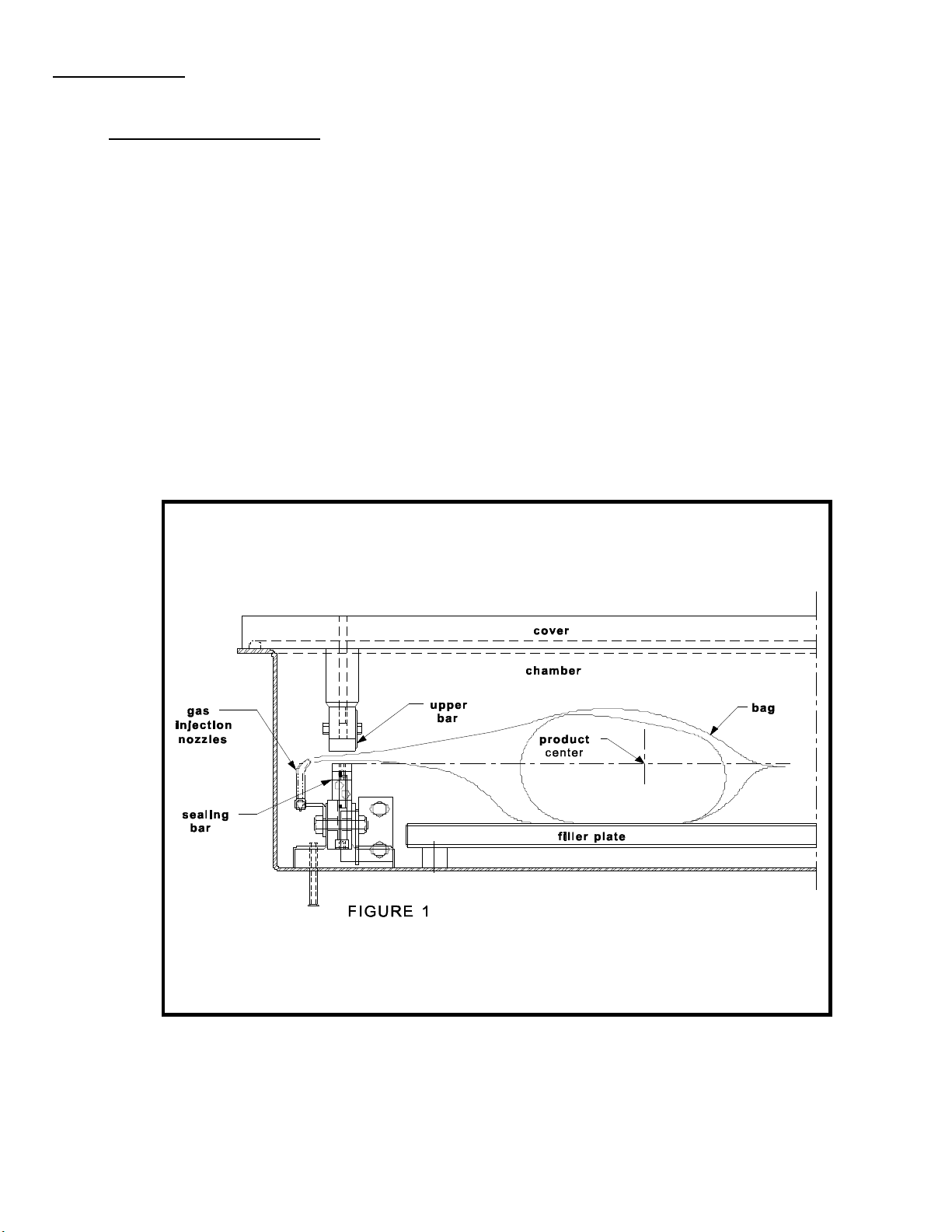
A vacuum packaging cycle is made of 3 stages. First the vacuum is made, the air is
completly taken out of the chamber and from bag containing the product. (See figure
1). Then it is possible to inject neutral gas from the nozzles, if the product is delicate.
Finally, a mechanism pushes the sealing bar to the rubber support to seal the bag.
To obtain nice packages, the products and the bags have to be of proportional
sizes. The bag's opening should never exceed 50 cm(2") past the seal bars. The
product should be centered in height in relation to the seal bar by adjusting the
spacers provided.
To obtain a good seal, make sure that no residue of fat is left between the bag's
inner sides where sealing is done.
Page 8

8
3.2 Special packaging:
3.2.1 Gas flushing (option):
There is an atmospheric pressure of 1 kg/ sq. cm (14 lbs/sq. inch) upon products when
fully evacuated. Products which can be damaged by high pressure must be packaged
with a partial vacuum, or the pressure must be counterbalance by inflating the bag with
gas (nitrogen or carbon dioxide) before sealing after evacuation.
For gas flushing, the bags are placed on the sealing bars, the open end placed over
the gas nozzles mounted alongside the sealing bar. After evacuation, the vacuum
valve closes and the gas valve opens. Gas time (sec.) can be set in the program
menu.
The necessary gas tank and pressure valve mounted on tank is not supplied, The
pressure of the gas regulator should be set at approximately 1/3 kg/sq. cm
( 5 lbs/sq.inch.). Each machine has an adaptor for gas connection when gas flush
option is ordered.
3.2.2 Electrical bag cut (optional):
This option is used to obtain a package that the excess bagtail is cut off close to the
seal (cannot be used with top and bottom sealing).
3.3 Vacuum packaging operation:
Note: Refer to the menus structure on page 14 and the keyboard detail on page 15.
3.3.1 Basics:
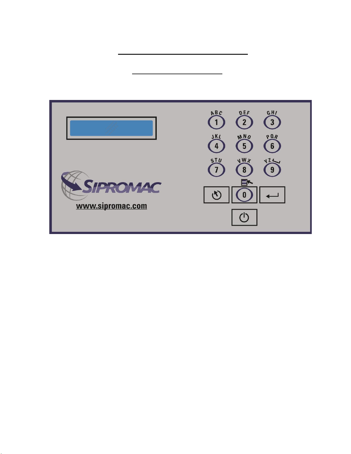
Use key "POWER" to power ON / OFF the vacuum packaging machine. When the
unit is energized, the identification of the last executed program is displayed on
LCD screen. To disconnect, use the "POWER" key to turn off the machine , then
remove plug from outlet. Do not unplug by pulling on cord. To unplug, grasp the
plug, not the cord. Unplug from outlet when not in use and before servicing or
cleaning.
Use the "ESC" key to change over from the programs menu to the functions menu
and from the functions menu to the programs menu.
In functions menu, use key "SELECT" to select a function and key
"ENTER" to accede and executed the selection.
In programs menu, use key "SELECT" to select a program and key
"ENTER" to accede and modify the selection.
In programs submenu, use key "ENTER" to pass over the parameters and point to
the following one; the parameters are blinking to point out the acquisition mode. A
return to programs menu is performed automatically following the last parameter
Page 9

9
acquisition.
In program submenu, use key "ESC" to get back to the programs menu. Strike any key
to clear the error messages which may be displayed on LCD screen.
3.3.2 Functions menu:
3.3.2.1 Create a program:
When executing the "create a program" function, the program submenu is
acceded, starting with the identification. The initial identification "Pxx NO NAME"
is given to the program and all parameters are established to zero; the program
number is allocated automatically.
3.3.2.2 Delete a program:
When executing the "delete a program" function, the programs menu is
acceded and the number of the first program in memory is blinking to point
out the deletion mode. Use key "SELECT" to select a program and key
"ENTER" to accede and confirm deletion of the selection. Use key "ESC" to
unconfirm a deletion and to leave the function. When leaving the function, the
number of the actual program on LCD screen cease to blink.
3.3.2.3 Select operating mode:
When executing the "select operating mode" function, which is available only for
the automatic units, the actual selection is blinking to point out the acquisition
mode. Use key "SELECT" to get through the operating modes, which are
automatic, semi-automatic and manual; the validation of the selected operating
mode is performed automatically. Use key "ESC" or "ENTER" to leave the
function and get back to the program menu.
3.3.3 Programs menu:
3.3.3.1 Program identification:
For a selected program, set the identification, using the numeric keyboard
characters chart; press numeric key until the desired character is selected (4
times for the numeric value). Use key "ENTER" to validate the character and to
validate the characters string at the end(the new characters string is blinking). In
a middle of an acquisition, use key "ESC" to come backward and erase one or
several characters.
Example: EXAMPLE 1 keys 2, 2, ENTER E
(9 characters) keys 8, 8, 8, ENTER X
keys 1, ENTER A
keys 5, ENTER M
keys 6, ENTER P
keys 4, 4, 4, ENTER L
Page 10

10
keys 2, 2, ENTER E
keys 9, 9, 9, ENTER space
keys 1, 1, 1, 1, ENTER 1
key ENTER to validate the characters string
3.3.3.2 Vacuum time setting (sensor disabled):
For a selected program set the vacuum time, in seconds; the validation is
automatically performed following the second digit entry (the new vacuum time is
blinking). In a middle of an acquisition, use key "ENTER" to validate the vacuum
time and key "ESC" to come backward and start over with a new acquisition (the
old vacuum time is blinking).
Examples: 1s keys 0, 1 or 1, ENTER
15s keys 1, 5
3.3.3.3 Vacuum level setting (sensor enabled)
For a selected program set the vacuum level, starting with the values; the
decimal point is automatically inserted following the second digit entry and the
validation is automatically performed following the third digit entry (the new
vacuum level is blinking). The vacuum level is rounded off to the nearest half
value. In the middle of an acquisition, use key "ENTER" to validate the vacuum
level and key "ESC" to come backward and start over with a new acquisition
(the old vacuum level is blinking). Set vacuum level to zero to bypass the
pressure transducer and proceed only using the vacuum plus time.
Examples: 90.0% keys 9, 0, 0 or 9, 0, ENTER or
keys 9, 0, 1 or 9, 0, 2 or 9, 0, 3 or 9, 0, 4
97.5% keys 9, 7, 5 or
keys 9, 7, 6 or 9, 0, 7 or 9, 0, 8 or 9, 0, 9
0.0% keys 0, 0, 0 or 0, ENTER
3.3.3.4 Vacuum plus time setting (sensor enabled)
For a selected program set the vacuum plus time, in seconds; the validation is
automatically performed following the second digit entry (the new vacuum plus
time is blinking). In a middle of an acquisition, use key "ENTER" to validate the
vacuum plus time and key "ESC" to come backward and start over with a new
acquisition (the old vacuum plus time is blinking).
Examples: 1s keys 0, 1 or 1, ENTER
15s keys 1, 5
3.3.3.5 Gas time setting (sensor disabled)
Page 11

11
For a selected program set the gas time setting following the same procedure as
for the vacuum time. Keep in mind that increasing gas time decrease sealing
pressure. Some vacuum must be kept inside to assure proper functioning.
3.3.3.6 Gas flush level setting: (sensor enabled)
For a selected program set the gas flush level following the same procedure as
for the vacuum level; the maximum gas flush level setting is 10% below the
vacuum setting.
3.3.3.7 Sealing time setting:
For a selected program set the sealing, starting with the seconds; the decimal point is
automatically inserted following the first digit entry and the validation is automatically
performed following the third digit entry (the new sealing time is blinking). The sealing
time is truncated to the nearest half hundredth. In a middle of an acquisition, use key
"ENTER" to validate the sealing time and key "ESC" to come backward and start over
with a new acquisition (the old sealing time is blinking).
Examples: 4.50s keys 4, 5, 0 or 4, 5, ENTER or
keys 4, 5, 1 or 4, 5, 2 or 4, 5, 3 or 4, 5, 4
2.35s keys 2, 3, 5 or
keys 2, 3, 6 or 2, 3, 7 or 2, 3, 8 or 2, 3, 9
0.00s keys 0, 0, 0 or 0, ENTER
3.3.4 Vacuum cycle execution:
For the manual units and the automatic units set on manual, close the cover to initiate
a vacuum cycle. For the automatic units set on semi-automatic or on automatic, use
push button "STOP / START" to initiate or interrupt a vacuum cycle. A selected
program can be initiated only in the programs menu, when no modifications are in
progress, and the access to the other programs and functions is denied. During cycle
execution the operation status is sequentially displayed on LCD screen, except for the
parameters established to zero, which are not displayed:
- Vacuum time or vacuum % status during vacuum sequence,
- Gas time or gas % status during gas flush sequence,
- Sealing time status during sealing sequence,
- ATM message during atmosphere sequence.
During cycle execution, use key "1" to abort the vacuum sequence and execute the
following sequence, which is gas flush or sealing, and key "ENTER" to accede and
modify the program; the parameters become valid only for the following vacuum
cycles.
Page 12

12
3.3.5 System monitor:
To accede the diagnostics menu, power up the vacuum packaging machine while
keeping pushed in the "ESC"key. Use key "SELECT" to select the system monitor
function and key "ENTER" to accede and visualize the monitored parameters. Use key
"SELECT" to change over from the software revision, the amount of working hours
done and the amount of complete cycles performed since first initialization.
Page 13

13
-MENUS STRUCTURE-
• Functions menu:
"F1 CREATE A PRGM"
"F2 DELETE A PRGM"
"F3 SELECT OPMODE" (automatic units only)
• Programs menu:
"Pxx NAME"
Program submenu:
"VACUUM: xx.xs" (10 – 199s)
"GAS FLUSH: xx.xs" (0 – 99s) (units with gas option)
"SEAL TIME: x.xxs" (0.00s - maximum unit allocated setting)
"Pxx NAME" (12 characters)
• Diagnostics menu (keys "ESC" & "POWER" for access):
"DIAGNOSTICS MENU" (access code required)
"D1 INPUTS TEST"
"D2 OUTPUTS TEST"
"D3 MODEL SELECT"
"D4 GAS OPTION"
"D5 SEALING TIME"
"D6 COOLING TIME"
"D7 OFFSET CALIB.”
"D8 VACUUM SENSOR”
"D9 SIPROMAC PUB”
"D10 LOADING TIME" (automatic units only)
"D11 UNLOADNG TIME" (automatic units only)
"SYSTEM MONITOR" (no access code required)
"SOFTWARE: R x.xx"
"WORK HRS: xxxxx"
"CYCLES: xxxxxxx"
Page 14
14
-KEYBOARD DETAILS-
MC-40 CONTROLS
Page 15

15
3.4 Daily cleaning:
For hygienic cleanliness, it is imperative to clean chamber and spacers daily. Also clean
the
lid rubber to assure tight seat of the lid.
Cleaning instructions for gas injection nozzles: Periodically on a regular basis the gas
injection nozzles must be removed with the connection tube and soaked in a food grade
soap and water solution, then dried and re-installed.
4. TROUBLE SHOOTING:
4.1 Failure during packaging cycle:
4.1.1 "COVER DOWN ERROR" message is displayed on LCD(manual units):
The input signal of the down position switch has been lost during cycle execution.
- Check limit switch adjustment.
4.2 Insufficient vacuum:
4.2.1 Leakage in the bag:
Most frequently, insufficient vacuum in bags is due to leakage in bag and not due
to any fault of the machine.
Pin-hole leak for which there is no obvious explanation is due to faulty bag
material.
Pin-hole leak caused by sharp edge of the product (bone, etc.).Use bone-guard
or thicker film.
Tear in bag by careless handling (sharp edge on filling table, damage made by
retailer or customer).
Leakage in lateral or bottom seal, complain to supplier of bags or film.
4.2.2 No leakage in the bag:
Bag is too large, therefore the surplus of air remains visible (there is surplus of air
in 0.4% of the bag volume in each bag). Use bags of suitable size.
Vacuum time is too short:
Pressure bar is jammed and closes opening of bag during evacuation.
4.2.3 Insufficient vacuum in chamber:
If troubles described under 4.2.1 and 4.2.2 do not apply, there is something
Page 16

16
wrong with the evacuation. To find the leakage quickly, check for leaks with a
precision vacuumeter, going back step by step from the chamber to the pump.
At the chamber (measuring point at base of valve) at maximum time of
evacuation. If more than 6 torr, proceed directly to the pump, if more than 3 torr:
have pump service by pump supplier. If pressure at pump is good, reconnect
hoses to pump and measure again.
Verify at vacuum hose connections and valve connections.
When proceeding this way, starting from pump, loss of pressure per step must
not exceed 0.5 to 1 torr.
Warning: Verify connections of measuring equipment before verifying machine.
Most frequent points of leakage: lid gasket, damaged vacuum hose or loose hose
clamps.
4.3 Faulty seal:
4.3.1 Insufficient seal:
Damaged teflon or silicone rubber.
Sealing pressure too low, bellows leaking or pressure bar jammed.
Leakers in seal: heating wire mechanically damaged (knicked) or silicone rubber
uneven.
4.3.2 No seal:
Sealing wire burnt.
Faulty contact in sealing circuit.
Sealing transformer burnt through.
Contactor does not work.
4.3.3 Permanent sealing current:
Contactor is jammed check sealing transformer for damage through overload.
4.3.4 Seal does not stick:
Insufficient layer of polyethylene (inferior quality of bags).
Seal area extremely contaminated by fat or meat juice. Use filling aid.
Sealing temperature is too low (when using very thick films).
Warning: Do not increase sealing time more than really necessary; higher
temperature will reduce working life of teflon and silicone rubber.
Page 17

17
4.4 Fault in the valve:
Vacuum or air valve does not open.
Check whether there is voltage on the magnetic valves during their period of operation.
If there is no voltage a wire is broken or the PC board is damaged.
Lid does not open at the end of the cycle; air enters, but there is still 20 - 40% vacuum
in chamber. Vacuum valve does not close.
4.5 MC40 Control board failure
NOTE: Refer to menu structure on page 14.
This board software is allowing access to a "Diagnostics Menu". Only qualified service
technicians are authorized to access this menu by entering a security password.
By acceding either the "D1 input test" feature or the "D2 output test" feature, a trained
technician will be able to quickly know the origin of the problem: pump,
sealing system, pneumatic problem, security switches problem, etc...
Keep in mind that in most cases trouble is due to a leakage, loose electrical Keynesian
or evident damage to the main component: vacuum pump, valves..., electrical
contactors, thermal overload, fuses holder or transformer.
For assistance do not hesitate to contact your local service technicians.
Page 18

18
5. REGULAR MAINTENANCE:
Routine controls to be made at regular intervals:
Check Teflon tape for wear.
Check silicone rubber for burnt spots and smooth even position.
Check pressure bar for jamming.
Check lid sealing for damage and hardened spots.
Check switch-point of micro switch, adjust if necessary.
Check evacuation hose for damage (contraction of diameter, or abrasions).
Check vacuum connections for tightness.
Check oil in pump (oil level in view glass; add if necessary. Regular oil change - necessity
indicated by color change).
Check vacuum in chamber with precision vacuumeter.
Check function of cycle with various settings of timers.
Page 19

19
MECHANICAL DRAWING
Page 20

005B0942
ITEM PART # DESCRIPTION QT.
31
32
DETAIL C
2
10
11
12
3
14 15161718 19
4
8
21
20
1 004-0346 "BUSCH" PUMP INSTALATION 1
2 005A0960 LEFT GAS INJECTION BAR ASS'Y 1
3 005A0961 FRONT GAS INJECTION BAR ASSEMBLY 1
4 005A0962 RIGHT GAS INJECTION BAR ASS'Y 1
5 005A1496 AIR REGULATOR VALVE ASSY 1
6 005A1497 GAS VALVE ASSY 1
7 005A1529 GAS VALVE ASSY 1
8 005B0941 BASE MACHINE ASSEMBLY 1
9 005B0972 STAND ASSEMBLY 1
10 005C0803 SEAL BAR ASSEMBLY 2
11 005C0882 LONG SEAL BAR ASSEMBLY 1
12 005C0882 LONG SEAL BAR ASSEMBLY 1
13 005C0967 SEAL BAR ASSEMBLY B.C.O. 2
14 033-0013 MC-40 KEYBOARD "CPI/GUARDIAN" 1
15 033-0014 MC-40 KEYBOARD "FOODPAK" 1
16 033-0015 MC-40 KEYBOARD "SIPROMAC" 1
17 033-0016 MC-40 KEYBOARD "HOLLYMATIC" 1
18 033-0018 MC-40 KEYBOARD "BERKEL" 1
19 033-0019 MC-40 KEYBOARD "BSA" 1
20 036-1510 MALE PLUG 20 AMP. / 125 V. 1
21 036-1512 MALE PLUG 15 AMP./ 250 V. 1
22 100-0225 CLOSE NIPPLE 1/4" NPT SS 1
23 100-0500 RED. BUSH. 1/4" NPT x 1/8" NPT SS 1
24 100-0510 RED.BUSH.1/2"NPT x 1/4"NPT S/S 1
25 100-0832 HEX. PLUG 1/2" NPT S/S 1
26 102-0362 Y BRANCH 3/8'' MNPT X 3/8'' T. QUICK 1
27 102-0410 MALE CONN.1/4"MNPTx3/8"T.QUICK 3
28 105-0218 EAR CLAMP 3/8" S/S 2
29 106-0010 VALVE 2WAY N.C. 24VAC 1/4'' NPT(SMC) 1
30 114-2050 EXHAUST MUFFLER 1/2 NPT S/S 1
31 127-0115 STICKER ELEC. CONN. 15A 2-1/2'' X 3-3/4'' 1
32 127-0120 STICKER ELEC. CONN. 20A 2-1/2'' X 3-3/4'' 1
LET. MODIFICATION
DATE
INT.
MACHINE
380T
9
PART
ITEM
MAT.
MACHINE ASSEMBLY
CNC
3D DWG BY
2D DWG BY
SBU
AG
DEPT. TOL.
USINAGE
TOLERIE
SOUDAGE
DATE
14-06-12
DATE
24-09-14
METRIC
INCH
± 0.1
± 0.004"
±
0.5
±
0.020"
±
0.
5
±
0.020"
N.T.S.
DEPT.
NO.
005B0942
SIPROMAC
ST-GERMAIN DE GRANTHAM
QUEBEC CANADA
M-I
QTY.
1
Page 21

005B0942
8
22
30
24
25
28
B
29
A
29
23
DETAIL A
28
7
26
1
6
5
27
DETAIL B
MACHINE
PART
ITEM
MAT.
380T
MACHINE ASSEMBLY
CNC
3D DWG BY
2D DWG BY
SBU
DEPT. TOL.
USINAGE
TOLERIE
SOUDAGE
DATE
14-06-12
DATE
METRIC
INCH
± 0.1
± 0.004"
±
0.5
±
0.020"
±
0.
5
±
0.020"
N.T.S.
DEPT.
NO.
005B0942
SIPROMAC
ST-GERMAIN DE GRANTHAM
QUEBEC CANADA
M-I
QTY.
1
Page 22

DETAIL B
11
12
8
15
13
4
7
005B0941
ITEM PART # DESCRIPTION QT.
30
22
2
DETAIL A
14
29
27
25
28
26
10
3
B
D
C
A
18
17
16
5
19
21
1 002-0024 HINGE BLOCK 2
2 002-0435 SEAL BAR GUIDE BLOCK 6
3 004-0261 LIMIT SWITCH ASS'Y 1
4 004A0042 ELEC. SUPPORT PRE-ASS'Y 1
5 004A1224 SPRING PRE-ASSEMBLY 2
6 004A1225 SPRING PRE-ASSEMBLY 2
7 004A4112 NSF FOOT 3
8 004B0595 VACUUM 380T PRE-ASSEMBLY 1
9 004C1223 REAR PANEL PRE-ASS'Y 1
10 005-0518 BELLOWS ASS'Y 2
11 005A0889 BELLOWS ASSEMBLY 1
12 005A0925 FILLER PLATE ASSEMBLY 2
13 005A1495 BELLOWS VALVE ASSY 1
14 005B0943 COVER ASSEMBLY 1
15 005C0944 FRONT PANEL ASSEMBLY 1
16 030-0120 CAB TIRE #12/3 SJ0W 1
17 036-0200 GROMMET 5/8"IDx1 1/8"OD RUBBER 1
18 036-0390 CABLE CONNECT.3/8"-1/2"METAL 1
19 036-0400 WIRE CONNECT. 3/8'' NPT
20 051-0232 SCREW 1/4-20x 1-1/4"SKT CAP SS 4
21 051-0580 NUT 1/4"-20 S/S 4
22 051-0581 NUT 1/4"-20 NYLON LOCK S/S 8
23 051-0740 WASHER 1/4" FLAT S/S 12
24 058-0030 NYLON SPACER 3/8IDx3/4ODx1/16 2
25 100-0075 STREET ELBOW 1/2" NPT SS 1
26 100-0230 CLOSE NIPPLE ½" npt, S/S 1
27 100-0330 NIPPLE 1/2'' NPT X 3'' SS 1
9
28 100-0493 CROSS 1/2'' NPT SS 1
29 100-1205 STRAIGHT ½"MNPTx3/4" HOSE BARB S/S 1
30 106-00201 VALVE 2WAY 24V 1/2'' NPT 1
CD09/O-RING/NUT
6
24
1
20
LET. MODIFICATION
6
DETAIL C
DATE
INT.
DETAIL D
23
MACHINE
380T
PART
BASE MACHINE ASSEMBLY
ITEM
MAT.
CNC
3D DWG BY
2D DWG BY
SBU
AG
DEPT. TOL.
USINAGE
TOLERIE
SOUDAGE
DATE
14-06-02
DATE
24-09-14
METRIC
INCH
± 0.1
± 0.004"
±
0.5
±
0.020"
±
0.
5
±
0.020"
N.T.S.
DEPT.
NO.
005B0941
SIPROMAC
ST-GERMAIN DE GRANTHAM
QUEBEC CANADA
M
QTY.
1
Page 23

005B0943
10
12
7
5
11
22
16
4
3
ITEM PART # DESCRIPTION QT.
1 001A3074 COVER REINFORCEMENT 1
2 002-0026 UPPER SEAL BAR SPACER 8
3 002A1295 BALL SPACER 1
4 002B1347 COVER REINFORCEMENT 1
5 002B1786 PLEXI COVER 1
6 004A0308 UPPER SEAL BAR PRE-ASS`Y 2
7 004A1215 COVER HINGE ASSEMBLY 1
8 004A1244 COVER HOLD DOWN ASS'Y 1
9 004A1559 LONG UPPER SEAL BAR PRE-ASS`Y 1
10 051-0249 SCREW 1/4-20x 1-1/2"PAN PHIL SS 8
11 051-0272 SCREW 1/4"-20 x 2 1/4" PAN PHIL S/S 1
12 051-0288 BOLT 1/4-20 x 3 1/2" S/S 8
13 051-0390 BOLT HEX. 3/8"-16nc. X 2" S/S 3
14 051-0393 SCREW 3/8"-16 x 2"SET HEX SKT SS 1
15 051-0580 NUT 1/4"-20 S/S 8
16 051-0581 NUT 1/4"-20 NYLON LOCK S/S 1
17 051-0740 WASHER 1/4" FLAT S/S 28
18 051-0750 WASHER 1/4" LOCK S/S 8
19 057-0001 BALL 1-3/8" x 3/8"-16 PLASTIC 1
20 076-0010 "O" RING 1/4" x 3/8" x 1/16" 8
21 076-0040 O RING 3/8" x 1/2" x 1/16" 3
22 179-0005 NEOPRENE SPONGE 3/8" O.D. (9'-6" ) 1
17
18
15
2
LET. MODIFICATION
19
14
8
1
20
MACHINE
380T
PART
DATE
9
INT.
6
ITEM
MAT.
COVER ASSEMBLY
CNC
3D DWG BY
2D DWG BY
SBU
AG
DEPT. TOL.
USINAGE
TOLERIE
SOUDAGE
DATE
14-08-06
DATE
23-09-14
METRIC
INCH
± 0.1
± 0.004"
±
0.5
±
0.020"
±
0.
5
±
0.020"
N.T.S.
DEPT.
NO.
005B0943
SIPROMAC
ST-GERMAIN DE GRANTHAM
QUEBEC CANADA
M-I
QTY.
1
Page 24

005C0944
ITEM PART # DESCRIPTION QT.
1 001C2670 FRONT PANEL 1
2 005B0583 MC-40 CONTROL BOARD 1
3 026-0025 1 N.C. CONTACT WITH BASE 1
6
4
4 026-0030 1 N.C. CONTACT BLOCK 1
5 026-0050 3 POSITION SELECTOR 1
6 051-01865 SCREW 1/4-20x 1/2"TRUSS SLOT SS 5
7 051-0571 NUT #10-24 S/S 6
3
LET. MODIFICATION
DATE
INT.
7
5
2
MACHINE
380T
PART
FRONT PANEL ASSEMBLY
ITEM
MAT.
1
CNC
3D DWG BY
2D DWG BY
SBU
AG
DEPT. TOL.
USINAGE
TOLERIE
SOUDAGE
DATE
14-06-12
DATE
23-09-14
METRIC
INCH
± 0.1
± 0.004"
±
0.5
±
0.020"
±
0.
5
±
0.020"
N.T.S.
DEPT.
NO.
005C0944
SIPROMAC
ST-GERMAIN DE GRANTHAM
QUEBEC CANADA
M
QTY.
1
Page 25

005B0583
ITEM PART # DESCRIPTION QT.
1 003A0403 CONTROL INSERT 1
2 051-0092 SCREW #4-40 x 1 1/4" FLAT SLT S/S 4
9
8
2
3 051-0713 WASHER #4 FLAT S/S 4
4 058-0120 CPVC SPACER 0.120" x 1/4" x 5/8" 4
5 051-0540 NUT #4-40 HEX S/S 8
6 051-0715 WASHER #4 LOCK SS 4
7 033-0038 MC-40 SENSOR VACUUM 1
8 051-01095 SCREW 8-32 x 1/2 FLAT SLOT SS 6
9 179-0004 NITRILE 1/2'' X 1/8'' AUTOCOLLANT X
1220mm long
3
4
5
6
5
1
1
LET. MODIFICATION
DATE
INT.
7
MACHINE
PART
ITEM
MAT.
VACUUM
MC-40 CONTROL BOARD
CNC
DWG BY
APP. BY
SBU
DEPT. TOL.
USINAGE
TOLERIE
SOUDAGE
DATE
13-11-21
DATE
METRIC
INCH
± 0.1
± 0.004"
±
0.5
±
0.020"
±
0.
5
±
0.020"
N.T.S.
DEPT.
NO.
005B0583
SIPROMAC
ST-GERMAIN DE GRANTHAM
QUEBEC CANADA
M
QTY.
1
Page 26

004C1223
ITEM PART # DESCRIPTION QT.
1 001C3063 REAR PANEL 1
2 051-0185 SCREW 1/4-20x 1/2"PAN PHIL S/S 4
3 051-0740 WASHER 1/4" FLAT S/S 4
1
3
DETAIL A
LET. MODIFICATION
A
2
MACHINE
380, 380T
PART
ITEM
DATE
INT.
MAT.
REAR PANEL PRE-ASS'Y
CNC
DWG BY
SBU (AG)
APP. BY
DEPT. TOL.
USINAGE
TOLERIE
SOUDAGE
DATE
14-06-03
DATE
METRIC
INCH
± 0.1
± 0.004"
±
0.5
±
0.020"
±
0.
5
±
0.020"
N.T.S.
DEPT.
NO.
004C1223
SIPROMAC
ST-GERMAIN DE GRANTHAM
QUEBEC CANADA
M
QTY.
1
Page 27

005C0968
ITEM PART # DESCRIPTION QT.
ITEM PART # DESCRIPTION QT.
1 004A0599 LONG SEAL BAR PRE- ASS'Y 1
4
3
2
1
5
4
5
6
5
7
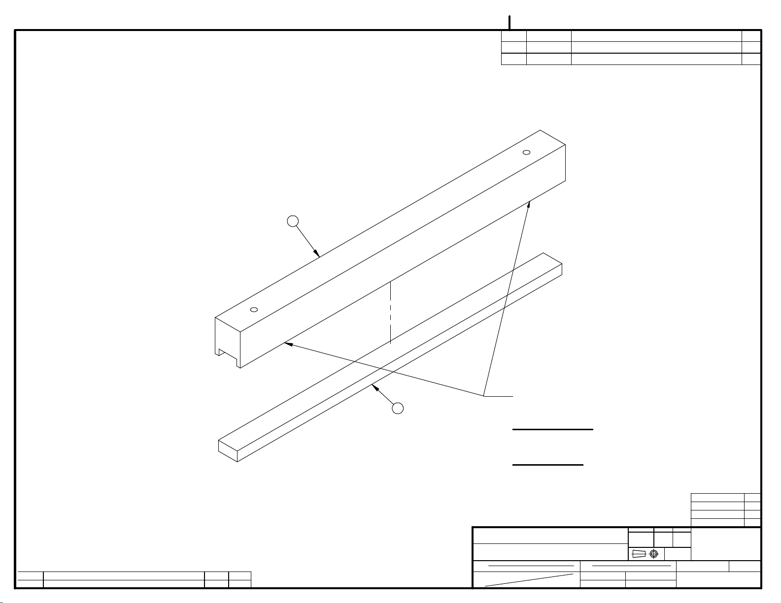
1 004A0599 LONG SEAL BAR PRE- ASS'Y 1
2 001A3521 LONG SEAL BAR REINFORCEMENT 1
2 001A3521 LONG SEAL BAR REINFORCEMENT 1
3 001A6812 SEAL BAR GUIDE 2
3 001A6812 SEAL BAR GUIDE 2
4 051-0230 HEX BOLT 1/4-20 x 1 1/4" SS 8
4 051-0230 HEX BOLT 1/4-20 x 1 1/4" SS 8
5 051-0740 WASHER 1/4" FLAT S/S 12
5 051-0740 WASHER 1/4" FLAT S/S 12
6 051-0581 NUT 1/4"-20 NYLON LOCK S/S 8
6 051-0581 NUT 1/4"-20 NYLON LOCK S/S 8
7 001B3519 LONG SEAL BAR SUPPORT 1
7 001B3519 LONG SEAL BAR SUPPORT 1
8 008B0749 LONG BELLOW SPACER 1
8 008B0749 LONG BELLOW SPACER 1
9 002A4235 SEAL BAR SUPPORT (LONG) 1
9 002A4235 SEAL BAR SUPPORT (LONG) 1
10 051-0275 SCREW 1/4-20 X 2-1/4'' FLAT SLOT S/S 5
10 051-0275 SCREW 1/4-20 X 2-1/4'' FLAT SLOT S/S 5
4
LET.
8
MODIFICATION
DATE
INT.
-END VIEW-
9
10
5
6
-BAG CUT OPTION-
MACHINE
PART
380T
LONG SEAL BAR ASSEMBLY
ITEM
MAT.
CNC
DWG BY
APP. BY
SBU
DEPT. TOL.
USINAGE
TOLERIE
SOUDAGE
DATE
14-08-06
DATE
METRIC
INCH
± 0.1
± 0.004"
±
0.5
±
0.020"
±
0.
5
±
0.020"
N.T.S.
DEPT.
NO.
005C0968
SIPROMAC
ST-GERMAIN DE GRANTHAM
QUEBEC CANADA
M
QTY.
1
Page 28

Page 29

005C0967
ITEM PART # DESCRIPTION QT.
1 001-1829 SEAL BAR GUIDE SPACER 2
7
1
5
10
2 001A6812 SEAL BAR GUIDE 2
3 001B1737 SEAL BAR SUPPORT 1
4 002A4231 SEAL BAR SUPPORT (SHORT) 1
5 004A1333 SEAL BAR PRE- ASS'Y 1
6 008B0677 ESPACEUR DE SOUFFLET 1
7 051-0230 HEX BOLT 1/4-20 x 1 1/4" SS 4
8 051-0275 SCREW 1/4-20 X 2-1/4'' FLAT SLOT S/S 3
9 051-0581 NUT 1/4"-20 NYLON LOCK S/S 4
10 051-0740 WASHER 1/4" FLAT S/S 4
9
2
4
8
LET. MODIFICATION
DATE
INT.
3
6
MACHINE
380T
PART
SEAL BAR ASSEMBLY B.C.O.
ITEM
MAT.
CNC
3D DWG BY
2D DWG BY
CF
AG
DEPT. TOL.
USINAGE
TOLERIE
SOUDAGE
DATE
12-04-19
DATE
23-09-14
METRIC
INCH
± 0.1
± 0.004"
±
0.5
±
0.020"
±
0.
5
±
0.020"
N.T.S.
DEPT.
NO.
005C0967
SIPROMAC
ST-GERMAIN DE GRANTHAM
QUEBEC CANADA
M-I-(M)
QTY.
2
Page 30

Page 31

005C0882
ITEM PART # DESCRIPTION QT.
ITEM PART # DESCRIPTION QT.
1 004A1558 LONG SEAL BAR PRE- ASS'Y 1
4
3
2
1
5
4
5
6
5
7
1 004A1558 LONG SEAL BAR PRE- ASS'Y 1
2 001A3521 LONG SEAL BAR REINFORCEMENT 1
2 001A3521 LONG SEAL BAR REINFORCEMENT 1
3 001A6812 SEAL BAR GUIDE 2
3 001A6812 SEAL BAR GUIDE 2
4 051-0230 HEX BOLT 1/4-20 x 1 1/4" SS 8
4 051-0230 HEX BOLT 1/4-20 x 1 1/4" SS 8
5 051-0740 WASHER 1/4" FLAT S/S 12
5 051-0740 WASHER 1/4" FLAT S/S 12
6 051-0581 NUT 1/4"-20 NYLON LOCK S/S 8
6 051-0581 NUT 1/4"-20 NYLON LOCK S/S 8
7 001B3519 LONG SEAL BAR SUPPORT 1
7 001B3519 LONG SEAL BAR SUPPORT 1
8 008B0749 LONG BELLOW SPACER 1
8 008B0749 LONG BELLOW SPACER 1
9 002A4235 SEAL BAR SUPPORT (LONG) 1
9 002A4235 SEAL BAR SUPPORT (LONG) 1
10 051-0275 SCREW 1/4-20 X 2-1/4'' FLAT SLOT S/S 5
10 051-0275 SCREW 1/4-20 X 2-1/4'' FLAT SLOT S/S 5
4
LET.
8
MODIFICATION
DATE
INT.
-END VIEW-
9
10
5
6
-TWIN SEAL OPTION-
MACHINE
PART
380T
LONG SEAL BAR ASSEMBLY
ITEM
MAT.
CNC
DWG BY
APP. BY
SBU
DEPT. TOL.
USINAGE
TOLERIE
SOUDAGE
DATE
14-08-06
DATE
METRIC
INCH
± 0.1
± 0.004"
±
0.5
±
0.020"
±
0.
5
±
0.020"
N.T.S.
DEPT.
NO.
005C0882
SIPROMAC
ST-GERMAIN DE GRANTHAM
QUEBEC CANADA
M
QTY.
1
Page 32

Page 33

005C0803
4
3
2
6
5
9
ITEM PART # DESCRIPTION QT.
1 004A1218 SEAL BAR PRE- ASS'Y 1
2 001-1829 SEAL BAR GUIDE SPACER 2
3 001A6812 SEAL BAR GUIDE 2
4 051-0230 HEX BOLT 1/4-20 x 1 1/4" SS 4
5 051-0740 WASHER 1/4" FLAT S/S 4
6 051-0581 NUT 1/4"-20 NYLON LOCK S/S 4
7 001B1737 SEAL BAR SUPPORT 1
8 008B0677 ESPACEUR DE SOUFFLET 1
9 002A4231 SEAL BAR SUPPORT (SHORT) 1
10 051-0275 SCREW 1/4-20 X 2-1/4'' FLAT SLOT S/S 3
LET.
7
MODIFICATION
DATE
INT.
8
-END VIEW-
10
-TWIN SEAL OPTION-
MACHINE
PART
ITEM
MAT.
380T
SEAL BAR ASSEMBLY
CNC
DWG BY
APP. BY
SBU
DEPT. TOL.
USINAGE
TOLERIE
SOUDAGE
DATE
14-08-06
DATE
METRIC
INCH
± 0.1
± 0.004"
±
0.5
±
0.020"
±
0.
5
±
0.020"
N.T.S.
DEPT.
NO.
005C0803
SIPROMAC
ST-GERMAIN DE GRANTHAM
QUEBEC CANADA
M
QTY.
2
Page 34

Page 35
004A0308
ITEM PART # DESCRIPTION QT.
1 002A0436 UPPER SEAL BAR SUPPORT 1
2 008-0435 UPPER SEAL BAR RUBBER 1
1
D
LET.
REDESSINER SE
MODIFICATION
12-04-02
DATE
CF
INT.
BOUCHER LES TROUS AVEC SILICONE (1690200)
2
MACHINE
PART
ITEM
MAT.
FILL THE HOLES WITH SILICONE (1690200)
-ATTENTION -:
SEULEMENT POUR NE PAS NUIRE AU BOULONNAGE
-WARNING -:
IT WILL NOT OBSTRUCT THE BOLTING
250 , 380 & 380T
UPPER SEAL BAR PRE-ASS`Y
BOUCHER EN SURFACE
FILL ONLY ON THE SURFACE, SO
DEPT. TOL.
METRIC
USINAGE
± 0.1
TOLERIE
±
SOUDAGE
0.5
±
0.
5
N.T.S.
CNC
CF
DATE
DATE
12-03-26
DWG BY
APP. BY
380T
380
250
MACHINE
INCH
± 0.004"
SIPROMAC
±
0.020"
±
0.020"
ST-GERMAIN DE GRANTHAM
QUEBEC CANADA
DEPT.
M
NO.
004A0308
QTY.
2
2
1
QTY
LIST
Page 36

Page 37

005B0972
ITEM PART # DESCRIPTION QT.
1 004B3994 STAND SHELF PRE-ASSY 1
2 051-0422 BOLT 3/8"-16nc. X 3¼" S/S 4
3 051-0780 WASHER 3/8" FLAT S/S 4
4 130-0190 PL. CASTER SWIVEL W/OUT BRAKE 2
5 130-0195 PL. CASTER SWIVEL W/BRAKE 2
6 051-0620 NUT 3/8"-16 NC S/S 4
1
2
3
4
5
LET.
MODIFICATION
DATE
INT.
6
-STAND OPTION-
MACHINE
PART
ITEM
MAT.
380 & 380T
STAND ASSEMBLY
CNC
DWG BY
APP. BY
AG
DEPT. TOL.
USINAGE
TOLERIE
SOUDAGE
DATE
14-08-04
DATE
METRIC
INCH
± 0.1
± 0.004"
±
0.5
±
0.020"
±
0.
5
±
0.020"
N.T.S.
DEPT.
NO.
005B0972
SIPROMAC
ST-GERMAIN DE GRANTHAM
QUEBEC CANADA
M
QTY.
1
Page 38

005A1529
ITEM PART # DESCRIPTION QT.
1 051-0144 SCREW #10-24 N.C 1/2"PAN PHIL. S/S 2
2 051-0571 NUT #10-24 S/S 2
3 102-0410 MALE CONN.1/4"MNPTx3/8"T.QUICK 2
4 106-0010 VALVE 2WAY N.C. 24VAC 1/4'' NPT(SMC) 1
1
4
LET. MODIFICATION
3
DATE
2
INT.
GAS OPTION
MACHINE
VACCUM
PART
GAS VALVE ASSY
ITEM
MAT.
CNC
3D DWG BY
2D DWG BY
AG
AG
DEPT. TOL.
USINAGE
TOLERIE
SOUDAGE
DATE
23-09-14
DATE
23-09-14
METRIC
INCH
± 0.1
± 0.004"
±
0.5
±
0.020"
±
0.
5
±
0.020"
N.T.S.
DEPT.
NO.
005A1529
SIPROMAC
ST-GERMAIN DE GRANTHAM
QUEBEC CANADA
M
QTY.
1
Page 39

005A1497
ITEM PART # DESCRIPTION QT.
1 051-0144 SCREW #10-24 N.C 1/2"PAN PHIL. S/S 2
2 051-0571 NUT #10-24 S/S 2
3 100-0065 STREET ELBOW 1/4" NPT SS 1
4 102-0345 BRANCH TEE 1/4'' MNPT X 3/8'' T.QUICK 1
5 102-0410 MALE CONN.1/4"MNPTx3/8"T.QUICK 1
6 106-0010 VALVE 2WAY N.C. 24VAC 1/4'' NPT(SMC) 1
6
3
LET. MODIFICATION
DATE
INT.
4
5
2
1
MACHINE
PART
ITEM
MAT.
VACCUM
GAS VALVE ASSY
CNC
DWG BY
APP. BY
SBU (A.G)
DEPT. TOL.
USINAGE
TOLERIE
SOUDAGE
DATE
14-06-10
DATE
METRIC
INCH
± 0.1
± 0.004"
±
0.5
±
0.020"
±
0.
5
±
0.020"
N.T.S.
DEPT.
NO.
005A1497
SIPROMAC
ST-GERMAIN DE GRANTHAM
QUEBEC CANADA
M
QTY.
1
Page 40
005A1496
ITEM PART # DESCRIPTION QT.
1 001A6811 AIR REGULATOR SUPPORT 1
2 051-0180 BOLT. HEX. 1/4"-20 NC. x 1/2" S/S 2
3 051-0740 WASHER 1/4" FLAT S/S 2
4 102-0330 ELBOW 1/4" NPT X 3/8" HOSE QUICK 2
5 114-01501 PRESSURE REGUL.0-100 PSI 1/4'' NPT W/
NUT
6 114-0236 PRESSURE GAUGE 30 PSI 1/8'' NPT
BOTTOM
6
1
1
1
LET. MODIFICATION
DATE
INT.
5
-AIR REGULATOR OPTION -
MACHINE
TABLE TOP VACUUM
PART
AIR REGULATOR VALVE ASSY
ITEM
MAT.
CNC
DWG BY
APP. BY
SBU (A.G)
4
DEPT. TOL.
USINAGE
TOLERIE
SOUDAGE
DATE
DATE
2
3
METRIC
± 0.1
±
0.5
±
0.
14-06-09
INCH
± 0.004"
SIPROMAC
±
0.020"
5
±
0.020"
ST-GERMAIN DE GRANTHAM
QUEBEC CANADA
N.T.S.
DEPT.
M
NO.
005A1496
QTY.
1
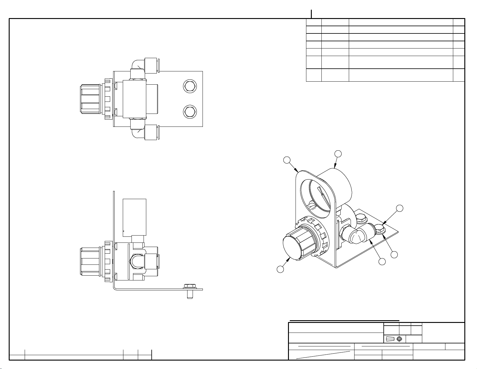
Page 41

VACCUM
FROM CHAMBER
11
005A1495
ITEM PART # DESCRIPTION QT.
1 001A0564 VALVE SUPPORT 1
2 051-0144 SCREW #10-24 N.C 1/2"PAN PHIL. S/S 4
3 051-0571 NUT #10-24 S/S 6
4 100-0225 CLOSE NIPPLE 1/4" NPT SS 1
5 100-0463 TEE 1/4" NPT S/S 1
6 101-0170 ELBOW 90° 1/4MNPTx1/4"HOSE 1
7 102-0345 BRANCH TEE 1/4'' MNPT X 3/8'' T.QUICK 1
8 102-0410 MALE CONN.1/4"MNPTx3/8"T.QUICK 1
9 104-0060 TUBE 3/8"OD x 1/4"ID POLYETHYL. 3
10 105-0218 EAR CLAMP 3/8" S/S 3
11 106-00701 VALVE 3WAY 24V 1/4''NPT 1
9
4
8
12 114-2020 FILTER / DRYER ¼"mnpt. X 1/4"t.p. COMP. 1
TO BELLOW
5
LET. MODIFICATION
DATE
INT.
12
TO MC-40
1
6
3
2
7
TO BELLOW
10
MACHINE
PART
ITEM
MAT.
380 & 380T
BELLOWS VALVE ASSY
CNC
DWG BY
APP. BY
SBU (A.G)
DEPT. TOL.
USINAGE
TOLERIE
SOUDAGE
DATE
13-11-14
DATE
METRIC
INCH
± 0.1
± 0.004"
±
0.5
±
0.020"
±
0.
5
±
0.020"
N.T.S.
DEPT.
NO.
005A1495
SIPROMAC
ST-GERMAIN DE GRANTHAM
QUEBEC CANADA
M
QTY.
1
Page 42

Page 43

Page 44

004-0346
ITEM PART # DESCRIPTION QT.
1 051-0740 WASHER 1/4" FLAT S/S 4
2 051-0950 BOLT M6 x 16 S/S 4
3 100-1205 STRAIGHT ½"MNPTx3/4" HOSE BARB S/S 1
4 104-0106 HOSE 1
5 105-0238 EAR CLAMP 23.9-27.1 SS 2
6 125-1020 BUSCH KB-0020 115V/1PH/60HZ 1
7 125-1021 BUSCH KB-0020 220-240V/1PH/50-60HZ 1
5
6
3
7
4
1
B
A
LET.
HOSE ADDED
ADDED 380T
MODIFICATION
14-06-10
06-01-26
DATE
A.G.
M.A.
INT.
2
MACHINE
350, 350D, 380 & 380T
PART
"BUSCH" PUMP INSTALATION
ITEM
MAT.
CNC
DWG BY
L.T. (A.G)
APP. BY
DEPT. TOL.
USINAGE
TOLERIE
SOUDAGE
DATE
02-03-11
DATE
METRIC
INCH
± 0.1
± 0.004"
±
0.5
±
0.020"
±
0.
5
±
0.020"
N.T.S.
DEPT.
NO.
004-0346
SIPROMAC
ST-GERMAIN DE GRANTHAM
QUEBEC CANADA
M
QTY.
1
Page 45

004-0261
ITEM PART # DESCRIPTION QT.
1 001-0944 SWITCH SUPPORT 1
2 026-0590 LIMIT SWITCH LONG ARM 1
3 027-0030 TERMINAL FEMALE 0.187" INSULATE 2
4 051-0080 SCREW 4-40 x 5/8" RND SLOT SS 2
5 051-0715 WASHER #4 LOCK SS 2
6 051-0540 NUT #4-40 HEX S/S 2
7 030-0631 22AWG/4COND.PVC,SHIELDED,300V. (1.7M) 1
8 030-0711 SHRINK 3/8'' BLACK 6" (0.52') 1
9 036-0850. 0.156'' CENTERLINE CRIMP TERMINAL 2
10 036-0820 0.156'' CENTERLINE CRIMP HOUSING 1
5
6
BLACK WIRE
FIL NOIR
1
4
10
9
2
BLACK WIRE
FIL NOIR
3
GREEN WIRE + BARE GROUND WIRE
TWISTED AROUND GREEN WIRE
FIL VERT + FIL DE "GROUND" DÉNUDÉ
ENTORTILLÉ AUTOUR DU FIL VERT
11
BEND 30
PLIER 30
v
v
7
GREEN WIRE
FIL VERT
PUSH UP TO ITEMS 3 AS FAR AS POSSIBLE
8
SHRINK ONLY ONCE INSTALLED INTO THE MACHINE
INSÉRER LE PLUS PRÈS POSSIBLE DE L'ITEM 3
CHAUFFER POUR LE RÉTRÉCISSEMENT SEULEMENT
UN FOIS INSTALLÉ DANS LA MACHINE
REDRAWN SE & LISTED ELECT. PART
H
LET.
MODIFICATION
12-03-26
DATE
CF
INT.
MACHINE
250, 350, 350D, 380, 380T
PART
LIMIT SWITCH ASS'Y
ITEM
MAT.
CNC
DWG BY
APP. BY
CF
DEPT. TOL.
USINAGE
TOLERIE
SOUDAGE
DATE
12-03-26
DATE
METRIC
INCH
± 0.1
± 0.004"
±
0.5
±
0.020"
±
0.
5
±
0.020"
N.T.S.
DEPT.
NO.
004-0261
SIPROMAC
ST-GERMAIN DE GRANTHAM
QUEBEC CANADA
M
QTY.
1
Page 46

20
ELECTRICAL DRAWING
Page 47
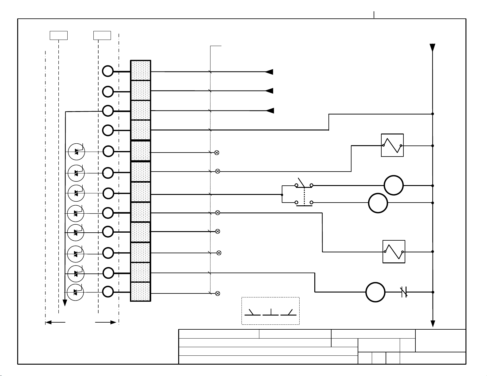
FULL FILENAME H:\PRODUITS\500-SIPROVAC\380T\ELECTRIQUE-PNEUMATIQUE\006-0438 380T CONT.VSD
006-0438
PAGE
1 de 2
in out
MC40
JP3/1
JP3/1
JP3/1
JP3/1
JP3/1
JP3/1
JP3/1
JP3/1
JP3/1
JP3/1
JP3/2
JP3/2
10
10
9
9
8
7
7
6
5
5
3
2
2
1
1
10
8
9
7
TRANSF.CONT.
W001
GREY
12
PURPLE
11
8
10
9
BROWN
YELLOW
F
BLUE N/A
6
8
ORANGE
2 w
1
yel. 25
Atmosphere
7
GREEN
4
4
6
SSW1
C2
C3
RED
3
5
WHITE
N/A
11
Sealing
(side)
Sealing
(front)
4
BLACK
3
BEIGE
2
PINK N/A
1
N/A
ooooooo
PUMP
C1
Positions for SSW1
3 w
G
OL/1
95
96
Bellows
Vacuum
PC BOARD
category
VACUUM PACK
system
usual
fonctions
options
Side All
model
Control MC-40
MC-40
Front
380-T
volt.
circuit
control
ALL
month
year
05 07 07
drawconcept
PP DLPP
day
app
SIPROMAC
block
St-Germain de Grantham
QUEBEC ,CANADA
006-0438
PAGE
1 de
2
Page 48

FULL FILENAME H:\PRODUITS\500-SIPROVAC\380T\ELECTRIQUE-PNEU MATIQUE\006-0438 380T CONT.VSD
in out
MC40
006-0438
TRANSF.CONT.
PAGE
2 de 2
JP4
JP4
JP4
JP4
WCV
1
2
3
4
1
2
3
4
shield
BLACK
WHITE N/A
RED N/A
GREEN
CV
ooooooo
yel. 25
PC BOARD
category
VACUUM PACK
system
usual
fonctions
options
model
Control MC-40
MC-40
380-T
volt.
circuit
control
ALL
month
year
05 04 14
drawconcept
PP DLPP
day
app
SIPROMAC
block
St-Germain de Grantham
QUEBEC ,CANADA
006-0438
PAGE
2 de
2
Page 49

FULL FILENAME H:\PRODUITS\500-SIPROVAC\380T\ELECTRIQUE-PNEUMATIQUE\006-0421 380T POW ER 120V 220V.V SD
006-0421
PAGE
1 de 2
Gnd
WAL
L1
N
C1 OL1
WM1
T1
T1
M 1
T5
F 1
T4
T4
XX
XX
Kw
HP
T8
WEL2
14 (blk)
C3
TR3
C3
F 2
WEL1
14 (blk)
C2
TR2
C2
F 2
20 (blk)
20 (blk)
F 5
02
04
category
system
usual
fonctions
options
TR1
VACUUM PACK
24V
9 V
pur
pur
1
red
2
red
F 4
F 3
model
MC-40
6
3
5
380-T
(20 yel)
(20 brn)
(20 pur)
(20 gry)
volt.
115-120 V 1 Ph 60 Hz
circuit
power
year
05 07 07
PP DLPP
month
drawconcept
25
24
13
6
day
app
SIPROMAC
block
St-Germain de Grantham
QUEBEC ,CANADA
006-0421
PAGE
1 de 2
Page 50

FULL FILENAME H:\PRODUITS\500-SIPROVAC\380T\ELECTRIQUE-PNEUMATIQUE\006-0421 380T POWER 120V 220V.VSD
006-0421
PAGE
2 de 2
Gnd
WAL
L1
L2
C1 OL1
WM1
T1
T1
M 1
T5
F 1
F 1
T4
T4
XX
XX
Kw
HP
T8
WEL2
14 (blk)
F 2
C3
TR3
C3
F 2
WEL1
14 (blk)
F 2
C2
TR2
C2
F 2
20 (blk)
20 (blk)
F 5
F 5
02
04
category
system
usual
fonctions
options
TR1
VACUUM PACK
24V
pur
9 V
pur
1
red
2
red
F 4
F 3
model
MC-40
6
3
5
380-T
(20 yel)
(20 brn)
(20 pur)
(20 gry)
volt.
208-230 V 1 Ph 60 Hz
circuit
power
year
05 07 07
PP DLPP
month
drawconcept
25
24
6
13
day
app
SIPROMAC
block
St-Germain de Grantham
QUEBEC ,CANADA
006-0421
PAGE
2 de 2
Page 51

FULL FILENAME H:\PRODUITS\500-SIPROVAC\380T\ELECTRIQUE-PNEUMATIQUE\006-0421 380T POWER 3 PH 208V.VSD
WAL
006-0421
PAGE
1 de 2
Gnd
L1
L3
L2
C1
OL1
F 1
F 1
F 1
M 1
HP
KW
WEL3
14 (blk)
14 (blk)
F 2
C3
C3
F 2
C2
F 2
C2
F 2
TR3
WEL1
TR2
20 (blk)
20 (blk)
F 5
F 5
02
04
category
system
usual
fonctions
options
TR1
VACUUM PACK
24V
pur
9 V
pur
1
red
2
red
F 4
F 3
model
MC-40
6
3
5
380-T
(20 yel)
(20 brn)
(20 pur)
(20 gry)
volt.
circuit
208 v 3 ph 60 hz
power
year
11 04 26
PP DLPP
month
drawconcept
25
24
13
6
day
app
SIPROMAC
block
St-Germain de Grantham
QUEBEC ,CANADA
006-0421
PAGE
1 de 2
Page 52

FULL FILENAME H:\PRODUITS\500-SIPROVAC\380T\ELECTRIQUE-PNEUMATIQUE\006-0421 380T POWER 3 PH 208V.VSD
006-0421
PAGE
2 de 2
Gnd
WAL
L1
L2
C1 OL1
WM1
T1
T1
M 1
T5
F 1
F 1
T4
T4
XX
XX
Kw
HP
T8
WEL2
14 (blk)
F 2
C3
TR3
C3
F 2
WEL1
14 (blk)
F 2
C2
TR2
C2
F 2
20 (blk)
20 (blk)
F 5
F 5
02
04
category
system
usual
fonctions
options
TR1
VACUUM PACK
24V
pur
9 V
pur
1
red
2
red
F 4
F 3
model
MC-40
6
3
5
380-T
(20 yel)
(20 brn)
(20 pur)
(20 gry)
volt.
208-230 V 1 Ph 60 Hz
circuit
power
year
05 07 07
PP DLPP
month
drawconcept
25
24
6
13
day
app
SIPROMAC
block
St-Germain de Grantham
QUEBEC ,CANADA
006-0421
PAGE
2 de 2
Page 53

21
PNEUMATIC DRAWING
Page 54

22
NOTES
 Loading...