

Page 1
1
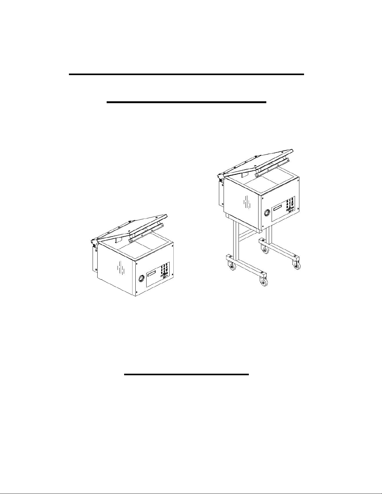
VACUUM PACKAGING MACHINE
MODELS 350 & 350D
OWNERS MANUAL
(MANUEL D’UTILISATION)
(MANUAL DE UTILIZACIÓN)
Page 2

2
Page 3

3
IMPORTANT SAFETY INSTRUCTIONS
SAVE THESE INSTRUCTIONS
This symbol points out important safety instructions which, if not followed, could
endanger the personal safety and/or property of your self and others . Read and follow
all instructions in this manual before attempting to operate your machine.
Failure to comply with these instructions may result in personal injury.
General Operation
• Read, understand, and follow all instructions in the manual and on the machine before
starting. Keep this manual in a safe place for further and regular reference and for ordering
replacement parts.
• Only allow responsible individuals familiar with the instructions to operate the machine. Be
sure to know controls and how to stop the machine quickly.
• Never put your hands near moving parts.
• Only allow qualified individuals for the maintenance of your machine.
• Remove all obstacles, which may interfere with the machine functions.
• Clear the work area such as electrical wires, buckets, knives etc.
• Be sure that everyone else is clear of your work area before operating the machine.
• Do not sit nor stand on the machine.
• Always turn off the machine after your work is done. Never leave a running machine
unattended.
• Always disconnect and wait till the machine has cooled before attempting any maintenance.
• Do not wear loose fitting clothes or jewelry as they may get caught in moving parts of the
machine.
• Always wear security shoes, to prevent injury caused by moving the machine or objects
falling from the machine.
• Never exceed the time limit to seal, which is recommended by the manufacturer. This is to
avoid any damage that may be caused to the sealing bars and to eliminate the risk of fire in
the machine. Thus avoiding corporal burns.
• Never touch the sealing bars after they have been used, this will avoid corporal burns. Wait
a few minutes to let the machine cool down before touching.
• Always make sure that the sealing bars are well installed in their "Guide Blocks" before
starting a cycle.
• Never incline the machine more than 30 degrees, it may tip over and hurt someone
seriously.
• Work only in daylight or good artificial light.
• Do not operate any appliance with a damaged cord or plug, or after the appliance
malfunctions or is dropped or damaged in any manner. Return appliance to the nearest
authorized service facility for examination, repair, or electrical or mechanical adjustment.
Do not operate the machine while under the influence of alcohol or dr ugs!
Page 4

4
Service
• Use proper containers when draining the oil. Do not use food or beverage containers that
may mislead someone into drinking from them. Properly dispose of the containers, or store
in a safe place immediately following the draining of the oil.
• Prior to disposal, determine the proper method to dispose of waste from your local office of
Environmental Protection Agency. Recycling centers are established to properly dispose of
materials in an environmentally safe fashion.
Do not pour oil or other fluids into the ground, down a drain or into a body of
water
.
Warning-Your responsibility:
This machine should only be operated by personal who c an read, understand and respect
warnings and instruc tions regarding this machine in the owners manual. Save these
instructions for future reference.
INSTALLATION NOTICE FOR MODELS:
250, 300, 350, 350D, 380 & 450T
IN ORDER TO RESPECT NSF REGULATIONS:
The table on which the machine has to be installed, should be of open frame type, to avoid dirt
accumulation, and to allow easy cleaning under the machine.
Page 5

5
VACUUM PACKAGING MACHINE
MODEL 350, 350D
(MC-40)
GENERAL TABLE OF CONTENTS
I OPERATION INSTRUCTIONS
II MECHANICAL
A- 350: front view assembly drawing.
B- 350: rear view assembly drawing
C- 350D: front view assembly drawing
D- 350D: rear view assembly drawing
E- 350 & 350D: front panel assembly
F- Seal bar assembly drawings (twin seal)
G- Seal bar assembly drawings (electrical bag cut option)
H- 350: cover assembly drawing
I- 350D: cover assembly drawing
J- 350 & 350D: upper seal bar assembly drawing
K- 350: gas injection kit installation drawing
L- 350D: gas injection kit installation drawing
III ELECTRICAL
A- Electrical drawings
IV PNEUMATIC
A- Pneumatic drawing
Page 6

6
VACUUM PACKAGING MACHINES-OPERATION INSTRUCTIONS
TABLE OF CONTENTS
1. Setting up the machine
2. Electrical connection
3. Operation
3.1 Working principles
3.2 Special packaging
3.2.1 Gas flushing
3.2.2 Electrical bag cut (optional)
3.3 Vacuum packaging operation
3.3.1 Basics
3.3.2 Functions menu
3.3.2.1 Create a program
3.3.2.2 Delete a program
3.3.2.3 Select operating mode
3.3.3 Programs menu
3.3.3.1 Program identification
3.3.3.2 Vacuum time setting (sensor disabled)
3.3.3.3 Vacuum level setting (sensor enabled)
3.3.3.4 Vacuum plus time setting (sensor enabled)
3.3.3.5 Gas time setting (sensor disabled)
3.3.3.6 Gas flush level setting (sensor enabled)
3.3.3.7 Sealing time setting
3.3.4 Vacuum cycle execution
3.3.5 System monitor
3.4 Daily cleaning
4. Trouble shooting
4.1 Failure during a packaging cycle
4.2 Insufficient vacuum
4.2.1 Leakage in the bag
4.2.2 No leakage in the bag
4.2.3 Insufficient vacuum in the chamber
4.3 Faulty seal
4.3.1 Insufficient seal
4.3.2 No seal
4.3.3 Permanent sealing current
4.3.4 Seal does not stick
4.4 Fault in the valves
4.5 Control board failure
5. Regular maintenance
2010-08-30
Page 7

7
VACUUM PACKAGING MACHINES
1. SETTING UP THE MACHINE:
Before choosing the site for the machine, pleas e consider that you wil l als o need room
for packaged and non-packaged products apart from the space needed for the
machine itself.
Keep in mind that the machine must not be set up upon uneven ground. Especially
with mobile models, the w eight of the pump might then cause warping of the machine.
Then the lid will not fit correctly.
Before starting to work, check the oil view glass on the pump, if there is a sufficient
quantity of oil in the pump. Never use oil other than recommended by the producer.
Never exceed maximum q uantity of oil indicated, w hen adding or changing oil. Veri fy
weekly.
Normal ambient temperature for the vacuum pump is between 10 to 70oC.For
temperature below 10oC; it is recommended to use synthetic oil. Please consult factory
and pump manufacturer manual for more information or when ambient temperature
are outside normal limits.
2. ELECTRICAL CONNECTION:
Electrical connections must be made by qualified per sonnel. This pers on must make
sure that the electric al ent ries cor respond to the proper voltag e and amperage of the
machine. GROUNDING INSTRUCTIONS: This appliance must be grounded. In the
event of malfunction or breakdown, g roundi ng prov i des a path of least resistance for
electric current to r educe the ri sk of electr ic s hock. This appl iance is equipped wi th a
cord having an equi pment-grounding conductor and a grounding plug . The plug must
be plugged into an appropriate outlet that is properly installed and grounded in
accordance with all local codes and ordinances.
DANGER Improper connection of the eq uipment-grounding conductor can resul t in a
risk of electric shock. The conductor with insulation having an outer surface that is
green with or w ithout yellow stripes i s the equipment-grounding conductor. If repair or
replacement of the cord or plug is necessary, do not connect the equipment-grounding
conductor to a live terminal. Check with a qualified electrician or serviceman if the
grounding instruc tions are not completely understood, or if in doubt as to whether the
appliance is properly grounded. Do not modify the plug provided with the appliance if it
will not fit the outlet; have a proper outlet installed by a qualified electrician.
All vacuum machines are supplied with an electrical schematic drawing. An
important step in connecting the machine is to make sure that the pump turns in its
correct rotation.
Page 8
8
The pump should not rotate more than 3 to 4 sec onds in the wrong rotation or it
may cause serious damage. The proper rotation is indicated by an arrow on the
pump motor.
3.OPERATION:
3.1 Working principles:
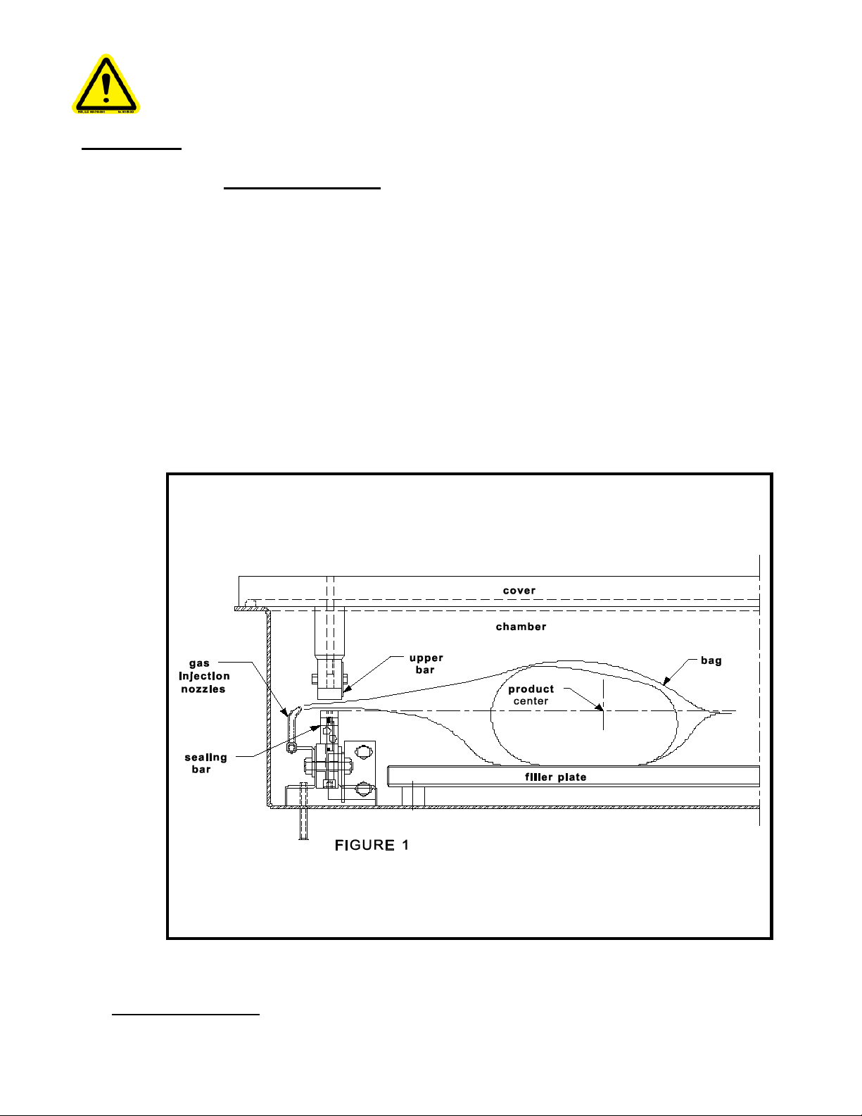
A vacuum packaging cy cl e i s made of 3 stag es. Fi r st the vacuum is made, the air is
completely taken out of the chamber and from bag containing the product. (See figure
1). Then it is possible to inject neutral gas from the nozz les, if the product i s delicate.
Finally, a mechanism pushes the sealing bar to the rubber support to seal the bag.
To obtain nice packages, the products and the bags have to be of proportional si zes.
The bag's opening should never exceed 50 cm(2") past the seal bars. The product
should be centered in height in relation to the seal bar by adjusting the spacers
provided.
To obtain a good seal, make sure that no residue of fat is left between the bag's
inner sides where sealing is done.
3.2 Special packaging:
Page 9

9
3.2.1 Gas flushing (option):
There is an atmospheric pressure of 1 kg/ sq . cm (14 lbs/sq. inch) upon produc ts when
fully evacuated. Products which can be damaged by high pressure must be packaged
with a partial v acuum, or the pressure must be counter balance by inflating the bag with
gas (nitrogen or carbon dioxide) before sealing after evacuation.
For gas flushing, the bags are placed on the sealing bars, the open end placed over
the gas nozzles mounted alongside the sealing bar. After evacuation, the vacuum
valve closes and the gas valve opens. Gas time (sec.) can be set in the program
menu.
The necessary gas tank and pressure valve mounted on tank is not supplied, The
pressure of the gas regulator should be set at approximately 1/3 kg/sq. cm
( 5 lbs/sq.inch.). Each machine has an adaptor for gas connection when gas flush
option is ordered.
3.2.2 Electrical bag cut (optional):
This option is used to obtain a package that the excess bagtail is cut off close to the
seal (cannot be used with top and bottom sealing).
3.3 Vacuum packaging operation:
Note: Refer to the menus structure on page 13 and the keyboard detail on page 14.
3.3.1 Basics:
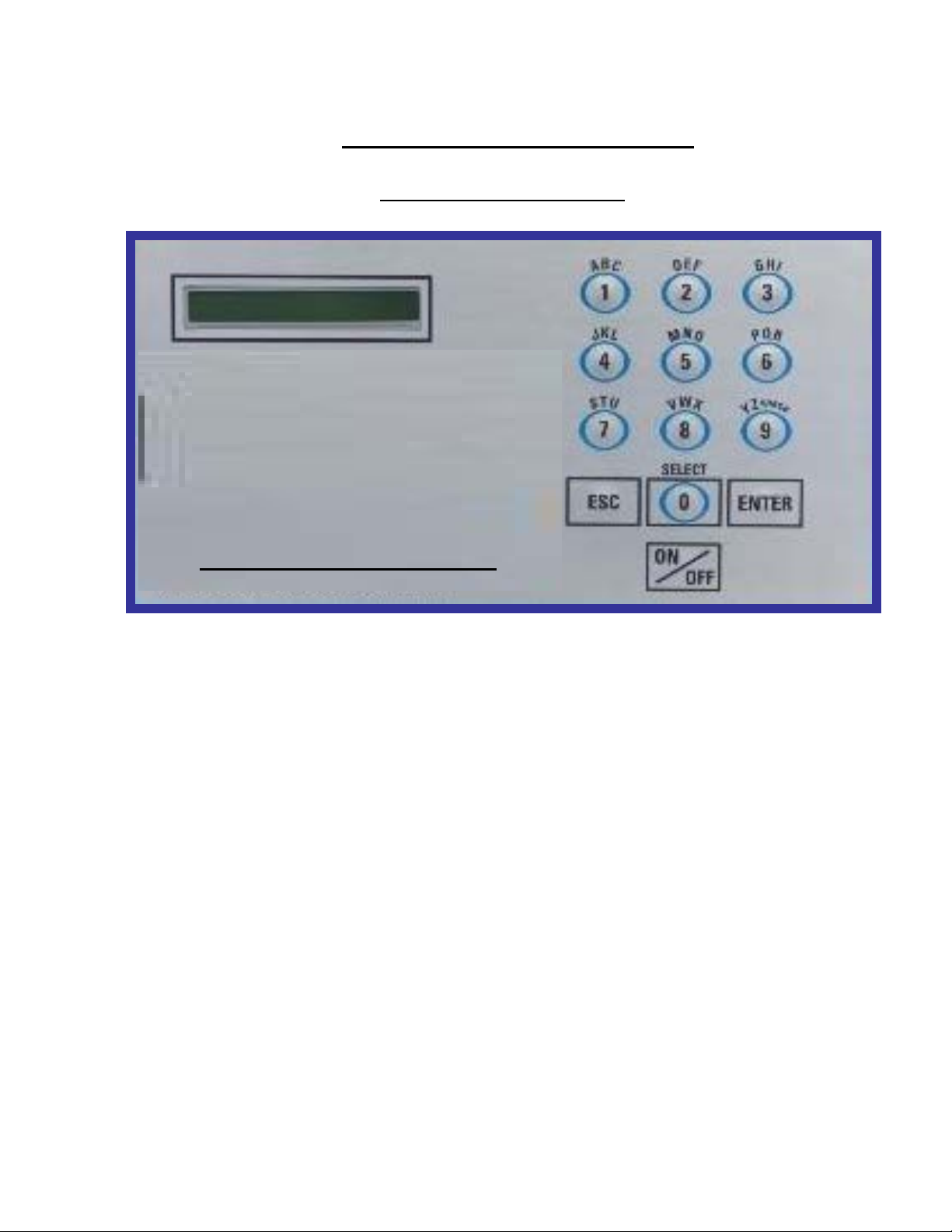
Use key "POWER" to power ON / OFF the vacuum packaging machine. When the
unit is energized, the identification of the last executed program is displayed on
LCD screen. To disconnect, use the "POWER" key to turn off the machine , then
remove plug from outlet. Do not unplug by pulling on cord. To unplug, grasp the
plug, not the cord. Unplug from outlet when not in use and before servicing or
cleaning.
Use the "ESC" key to change over from the programs menu to the functions menu
and from the functions menu to the programs menu.
In functions menu, use key "SELECT" to select a function and key
"ENTER" to accede and executed the selection.
In programs menu, use key "SELECT" to select a program and key
"ENTER" to accede and modify the selection.
In programs submenu, use key "ENTER" to pass over the parameters and point to
the following one; the parameters are blinking to point out the acquisition mode. A
return to programs menu is performed automatically following the last parameter
acquisition.
In program submenu, use key "ESC" t o get back to the progr ams me nu. Str ike a ny ke y
Page 10

10
to clear the error messages which may be displayed on LCD screen.
3.3.2 Functions menu:
3.3.2.1 Create a program:
When executing the "create a program" function, the program submenu is
acceded, starting w ith the identification. The initial identi fication "Px x NO NAME "
is given to the program and all parameters are est ablished to zer o; the program
number is allocated automatically.
3.3.2.2 Delete a program:
When executing the "delete a program" function, the programs menu is
acceded and the number of the first program in memory is blinking to point
out the deletion mode. Use key "SELECT" to select a program and key
"ENTER" to accede and confirm deletion of the selection. Use key "ESC" to
unconfirm a deletion and to leave the function. When leaving the function, the
number of the actual program on LCD screen cease to blink.
3.3.2.3 Select operating mode:
When executing the "select operating mode" function, whi ch is available only for
the automatic units, the actual selection is blinking to point out the acquisition
mode. Use key "SELECT" to get through the operating modes, which are
automatic, semi-automatic and manual; the vali dation of the selected operating
mode is performed automatically. Use key "ESC" or "ENTER" to leave the
function and get back to the program menu.
3.3.3 Programs menu:
3.3.3.1 Progr am identification:
For a selected program, set the identification, using the numeric keyboard
characters chart; press numeric key until the desired character is selected (4
times for the numeric value). U se key "ENTER" to v alidat e the charac ter and to
validate the characters string at the end(the new characters str ing is bl inking). In
a middle of an acquisition, use key "ESC" to come backward and erase one or
several characters.
Example: EXAMPLE 1 keys 2, 2, ENTER E
(9 characters) keys 8, 8, 8, ENTER X
keys 5, ENTER M
keys 1, ENTER A
keys 6, ENTER P
keys 4, 4, 4, ENTER L
keys 2, 2, ENTER E
keys 9, 9, 9, ENTER space
keys 1, 1, 1, 1, ENTER 1
key ENTER to validate the characters string
Page 11

11
3.3.3.2 Vacuum time setting (sensor disabled):
For a selected program set the vacuum time, in seconds; the validation is
automatically performed following the second digit entry (the new vacuum time is
blinking). In a middle of an acq uisition, use key "ENTER" to v alidate the vacuum
time and key "ESC" to come backward and start ov er with a new acq uisition ( the
old vacuum time is blinking).
Examples: 1s keys 0, 1 or 1, ENTER
15s keys 1, 5
3.3.3.3 Vacuum level setting (sensor enabled)
For a selected program set the vacuum level, starting with the values; the
decimal point is automatically inserted following the second digit entry and the
validation is automatically performed following the third digit entry (the new
vacuum level is blinking). The vacuum level is rounded off to the nearest half
value. In the middle of an acquisition, use key "ENTER" to validate the vacuum
level and key "ESC" to come backward and start over with a new acquisition
(the old vacuum level is blinking). Set vacuum level to zero to bypass the
pressure transducer and proceed only using the vacuum plus time.
Examples: 90.0% keys 9, 0, 0 or 9, 0, ENTER or
keys 9, 0, 1 or 9, 0, 2 or 9, 0, 3 or 9, 0, 4
97.5% keys 9, 7, 5 or
keys 9, 7, 6 or 9, 0, 7 or 9, 0, 8 or 9, 0, 9
0.0% keys 0, 0, 0 or 0, ENTER
3.3.3.4 Vacuum plus time setting (sensor enabled)
For a selected program set the vacuum plus time, in seconds; the validation is
automatically performed following the second digit entry (the new vacuum plus
time is blinking). In a middle of an acquisition, use key "ENTER" to validate the
vacuum plus time and key "ESC" to come backward and start over with a new
acquisition (the old vacuum plus time is blinking).
Examples: 1s keys 0, 1 or 1, ENTER
15s keys 1, 5
3.3.3.5 Gas time setting (sensor disabled)
For a selected program set t he gas time setting followi ng the same procedure as
for the vacuum time. Keep in mind that increasing gas time decrease sealing
pressure. Some vacuum must be kept inside to assure proper functioning.
Page 12

12
3.3.3.6 Gas flush level setting: (sensor enabled)
For a selected program set the gas flush level following the same procedure as
for the vacuum level; the maximum gas flush level setting is 10% below the
vacuum setting.
3.3.3.7 Sealing time setting:
For a selected program set the sealing, starting with the seconds; the decimal point is
automatically insert ed follow ing the first di git entry and the val idation is automatic ally
performed following the thir d digit entry ( the new sealing time is bli nking). The s ealing
time is truncated to the nearest half hundredth. In a middle of an acquisi tion, use key
"ENTER" to validate the sealing time and key "ESC" to come backw ard and start over
with a new acquisition (the old sealing time is blinking).
Examples: 4.50s keys 4, 5, 0 or 4, 5, ENTER or
keys 4, 5, 1 or 4, 5, 2 or 4, 5, 3 or 4, 5, 4
2.35s keys 2, 3, 5 or
keys 2, 3, 6 or 2, 3, 7 or 2, 3, 8 or 2, 3, 9
0.00s keys 0, 0, 0 or 0, ENTER
3.3.4 Vacuum cycle execution:
For the manual units and the automatic units s et on manual, close the c over to init iate
a vacuum cycle. For the automatic units set on semi-automati c or on aut omatic , use
push button "STOP / START" to initiate or interrupt a vacuum cycle. A selected
program can be initiated only in the programs menu, when no modifications are in
progress, and the access to the other programs and functi ons is denied. During cycle
execution the operation status i s sequentially displayed on LCD screen, ex cept for the
parameters established to zero, which are not displayed:
- Vacuum time or vacuum % status during vacuum sequence,
- Gas time or gas % status during gas flush sequence,
- Sealing time status during sealing sequence,
- ATM message during atmosphere sequence.
During cycle execution, use key "1" to abort the vacuum sequence and execute the
following sequence, which is gas flush or sealing, and key "ENTER" to accede and
modify the program; the parameters become valid only for the following vacuum
cycles.
3.3.5 System monitor:
To accede the diagnostics menu, power up the vacuum packaging machine while
keeping pushed in the "ESC"key. Use key "SELECT" to select the system monitor
function and key "ENTER" to accede and visualize the monitored parameters. Use k ey
"SELECT" to change over from the software revision, the amount of working hours
done and the amount of complete cycles performed since first initialization.
Page 13

13
-MENUS STRUCTURE-
• Functions menu:
"F1 CREATE A PRGM"
"F2 DELETE A PRGM"
"F3 SELECT OPMODE" (automatic units only)
• Programs me nu:
"Pxx NAME"
Program submenu:
"VACU UM: xx.x%" (10.0% - 99.5%)
"VACUUM PLUS: xxs" (0s - 99s)
"VACU UM: xx.xs" (10 – 199s) (sensor disabled in D8 menu)
"GAS FLUSH: xx.xs" (0 – 99s) (units with gas option) (sensor disabled in D8)
"GAS FLUSH: xx.x%" (0.0% - 10% below the vacuum level) (units with gas option)
"SEAL TIME: x.xxs" (0.00s - maximum unit allocated setting)
"Pxx NAME" (12 characters)
• Diagnostics menu (keys "ESC" & "POWER" for access):
"DIAGNOSTICS MENU" (access code required)
"D1 INPUTS TEST"
"D2 OUTPUTS TEST"
"D3 MODEL SELECT"
"D4 GAS OPTION"
"D5 SEALING TIME"
"D6 COOLING TIME"
"D7 OFFSET CALIB”
"D8 VACUUM SENSOR”
"D9 SIPROMAC PUB”
"D10 LOADING TIME" (automatic units only)
"D11 UNLOADNG TIME" (automatic units only)
"SYSTEM MONITOR" (no access code required)
"SOFTWARE: R x.xx"
"WORK HRS: xxxxx"
"CYCLES: xxxxxxx"
Page 14
14
-KEYBOARD DETAILS-
MC-40 CONTROLS
MC-40 CONTROLS
Page 15

15
WARNING: All electrical work described in this brochure should be done by
a QUALIFIED and AUTHORIZED technician
.
3.4 Daily cleaning
For hygienic cleanliness, it is imperative to clean chamber and spacers daily. Also clean the
lid rubber to assure tight seat of the lid.
Cleaning instructions for gas injection nozzl es: Periodically on a regular basis the gas
injection nozzles must be removed with the connection tube and soaked in a food grade
soap and water solution, then dried and re-installed.
4. TROUBLE SHOOTING:
4.1 Failure during pac kaging cycle:
4.1.1 "COVER DOWN ERROR" message is displayed on LCD(manual units):
The input signal of the down position switch has been lost during cycle execution.
- Check limit switch adjustment.
4.2 Insufficient vacuum:
4.2.1 Leakage in the bag:
Most frequently, insufficient vacuum in bags is due to leakage in bag and not due
to any fault of the machine.
Pin-hole leak for which there is no obvious explanation is due to faulty bag
material.
Pin-hole leak caused by sharp edge of the product (bone, etc.).Use bone-guard
or thicker film.
Tear in bag by careless handling (sharp edge on filling table, damage made by
retailer or customer).
Leakage in lateral or bottom seal, complain to supplier of bags or film.
4.2.2 No leakage in the bag:
Bag is too large, therefore the surplus of air remains visible (there is surplus of air
in 0.4% of the bag volume in each bag). Use bags of suitable size.
Vacuum time is too short:
Pressure bar is jammed and closes opening of bag during evacuation.
4.2.3 Insufficient vacuum in chamber:
If troubles described under 4.2.1 and 4.2.2 do not apply, there is something wrong
with the evacuation. To find the leakage quickly, check for leaks with a precision
Page 16

16
vacuumeter, going back step by step from the chamber to the pump.
At the chamber (measuring point at base of valve) at maximum time of
evacuation. If more than 6 torr, proceed directly to the pump, if more than 3 torr:
have pump service by pum p supplier. If pressure at pump is good, reconnect
hoses to pump and measure again.
Verify at vacuum hose connections and valve connections.
When proceeding this way, starting from pump, loss of pressure per step must not
exceed 0.5 to 1 torr.
Warning: Verify connections of measuring equipment before verifying machine.
Most frequent points of leakage: lid gasket, damaged vacuum hose or loose hose
clamps.
4.3 Faulty seal:
4.3.1 Insufficient seal:
Damaged teflon or silicone rubber.
Sealing pressure too low, bellows leaking or pressure bar jammed.
Leakers in seal: heating wire mechanically damaged (knicked) or silicone rubber
uneven.
4.3.2 No seal:
Sealing wire burnt.
Faulty contact in sealing circuit.
Sealing transformer burnt through.
Contactor does not work.
4.3.3 Permanent sealing current:
Contactor is jammed check sealing transformer for damage through overload.
4.3.4 Seal does not stick:
Insufficient layer of polyethylene (inferior quality of bags).
Seal area extremely contam inated by fat or meat juice. Use filling aid.
Sealing temperature is too low (when using very thick films).
Warning: Do not increase sealing time more than really necessary; higher
temperature will reduce working life of teflon and silicone rubber.
4.4 Fault in the valve:
Vacuum or air valve does not open.
Page 17

17
Check whether there is voltage on the magnetic valves during their period of operation.
If there is no voltage a wire is broken or the PC board is damaged.
Lid does not open at the end of the cycle; air enters, but there is still 20 - 40% vacuum
in chamber. Vacuum valve does not close.
4.5 MC40 Control board failure
NOTE: Refer to menu structure on page 13.
This board software is allowing access to a "Diagnostics Menu". Only qualified service
technicians are authorized to access this menu by entering a security password.
By acceding either the "D1 input test" feature or the "D2 output test" feature, a trained
technician will be able to quickly know the origin of the problem: pump,
sealing system, pneumatic problem, security switches problem, etc...
Keep in mind that in most cases trouble is due to a leakage, loose electrical Keynesian
or evident damage to the main component: vacuum pump, valves..., electrical
contactors, thermal overload, fuses holder or transformer.
For assistance do not hesitate to contact your local service technicians.
5. Regular maintenance:
Routine controls to be made at regular intervals:
Check teflon for wear.
Check silicone rubber for burnt spots and smooth even position.
Check pressure bar for jamming.
Check lid sealing for damage and hardened spots.
Check switch-point of micro switch, adjust if necessary.
Check evacuation hose for damage (contraction of diameter, or abrasions).
Check vacuum connections for tightness.
Check oil in pump (oil level in view glass; add if necessary. Regular change of oil - necessity
indicated by change of color).
Check vacuum in chamber with precision vacuumeter.
Check function of cycle with various settings of timers.
Page 18
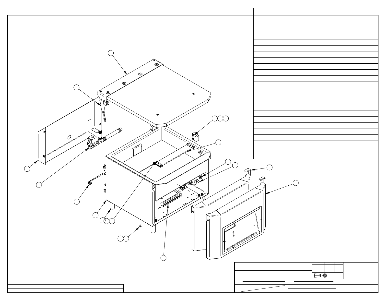
004A4142
ITEM PART # DESCRIPTION QT.
1 004B0229 VACUUM PRE-ASSEMBLY 1
2 005B0266 COVER ASSEMBLY 1
3 004A1224 SPRING PRE-ASSEMBLY 2
4 005E0832 MC-40 FRONT PANEL ASSEMBLY 1
2
3
1998
17
14
7
5
5 004A4144 VALVE ASSEMBLY VACCUM SENSOR 1
6 004A4133 VALVE ASSEMBLY PUMP 1
7 004C3857 REAR PANNEL PRE-ASS'Y 1
8 051-0740 WASHER 1/4" FLAT S/S 8
9 051-0581 NUT 1/4"-20 NYLON LOCK S/S 4
10 051-0930 BOLT M6 x 10 S/S 4
11 004A4112 NSF FOOT 4
12 004A3374 LIMIT SWITCH ASS'Y 1
13 004-0042 ELEC. SUPPORT PRE-ASS'Y 1
14 036-0400 WIRE CONNECT. 3/8'' NPT
CD09/O-RING/NUT
15 036-0200 GROMMET 5/8"IDx1 1/8"OD RUBBER 1
16 036-0390 CABLE CONNECT.3/8"-1/2"METAL 1
17 005-0532 BELLOWS ASSEMBLY 1
18 002-0029 LEFT SEAL BAR GUIDE BLOCK 1
19 002-0030 RIGHT SEAL BAR GUIDE BLOCK 1
20 005A0278 FILLER PLATE ASS'Y 1
21 005A0364 HALF FILLER PLATE ASS'Y 2
22 005A1584 MC-40 FRONT PANEL ASSEMBLY (BERKEL) 1
22 BERKEL
2
6
A
LET. MODIFICATION
BERKEL OPTION ADDED
4
12
1
11
20
21
108
13
15-02-24
DATE
SBU
INT.
MACHINE
PART
ITEM
MAT.
350
MACHINE ASSEMBLY
CNC
DWG BY
APP. BY
S.L.
DEPT. TOL.
USINAGE
TOLERIE
SOUDAGE
DATE
13-11-22
DATE
METRIC
INCH
± 0.1
± 0.004"
±
0.5
±
0.020"
±
0.
5
±
0.020"
N.T.S.
DEPT.
NO.
004A4142
SIPROMAC
ST-GERMAIN DE GRANTHAM
QUEBEC CANADA
M
QTY.
1
Page 19

004A4136
ITEM PART # DESCRIPTION QT.
1 004B0230 VACUUM PRE-ASSEMBLY 1
2 005B0481 COVER ASSEMBLY 1
3
2
18
9
19
6
17
5
22 BERKEL
4
7
3 004A1224 SPRING PRE-ASSEMBLY 2
4 005E0832 MC-40 FRONT PANEL ASSEMBLY 1
5 004B4134 VALVE ASSEMBLY VACCUM SENSOR 1
6 004A4133 VALVE ASSEMBLY PUMP 1
7 004C3857 REAR PANNEL PRE-ASS'Y 1
8 051-0740 WASHER 1/4" FLAT S/S 12
9 051-0581 NUT 1/4"-20 NYLON LOCK S/S 8
10 051-0930 BOLT M6 x 10 S/S 4
11 004A4112 NSF FOOT 4
12 004A3374 LIMIT SWITCH ASS'Y 1
13 004-0042 ELEC. SUPPORT PRE-ASS'Y 1
14 036-0400 WIRE CONNECT. 3/8'' NPT
CD09/O-RING/NUT
15 036-0200 GROMMET 5/8"IDx1 1/8"OD RUBBER 1
16 036-0390 CABLE CONNECT.3/8"-1/2"METAL 1
17 005-0532 BELLOWS ASSEMBLY 1
18 002-0029 LEFT SEAL BAR GUIDE BLOCK 2
19 002-0030 RIGHT SEAL BAR GUIDE BLOCK 2
20 005A0365 FILLER PLATE ASS'Y 2
21 036-0400 WIRE CONNECTOR 3/8'' NPT NUT 2
22 005A1584 MC-40 FRONT PANEL ASSEMBLY (BERKEL) 1
23 001A0564 VALVE SUPPORT 1
24 051-0143 SCREW 10-24 x 3/8" PAN PHIL S/S 2
25 051-0571 NUT #10-24 S/S 2
4
12
1
A
LET. MODIFICATION
BERKEL OPTION ADDED
11
20
14
8 10
13
15-02-23
DATE
SBU
INT.
MACHINE
PART
ITEM
MAT.
350D
MACHINE ASSEMBLY
CNC
DWG BY
APP. BY
S.L.
DEPT. TOL.
USINAGE
TOLERIE
SOUDAGE
DATE
13-11-22
DATE
METRIC
INCH
± 0.1
± 0.004"
±
0.5
±
0.020"
±
0.
5
±
0.020"
N.T.S.
DEPT.
NO.
004A4136
SIPROMAC
ST-GERMAIN DE GRANTHAM
QUEBEC CANADA
M
QTY.
1
Page 20

005C0610
ITEM PART # DESCRIPTION QT.
1 004A4142 MACHINE ASSEMBLY 1
1
A
2
2 005B1031 STAND ASSEMBLY 19" (OPTION) 1
3 125-1021 BUSCH KB-0020 220-240V/1PH/50-60HZ 1
4 114-2009 SILENCER 1/2 NPT TOPRING 1
5 005A1424 GAS OPTION 1
6 005A1420 SOFT AIR OPTION 1
7 005A1421 AIR OPTION 1
8 005A1355 SEAL BAR ASSEMBLY W/SUPP. TWIN SEAL 1
9 005A1356 SEAL BAR ASSEMBLY W/SUPP. BAG CUT 1
10 125-1020 BUSCH KB-0020 115V/1PH/60HZ 1
6
DETAIL A
LET. MODIFICATION
DATE
INSTALLER SUR LA VALVE LORS
4
DE L'OPTION SOFT AIR
7
3 10
MACHINE
350
5
INT.
PART
MACHINE ASSEMBLY WITH OPTION
ITEM
MAT.
CNC
DWG BY
APP. BY
S.L.
DEPT. TOL.
USINAGE
TOLERIE
SOUDAGE
DATE
13-11-22
DATE
METRIC
INCH
± 0.1
± 0.004"
±
0.5
±
0.020"
±
0.
5
±
0.020"
N.T.S.
DEPT.
NO.
005C0610
SIPROMAC
ST-GERMAIN DE GRANTHAM
QUEBEC CANADA
M-I
QTY.
1
Page 21

005B0611
ITEM PART # DESCRIPTION QT.
1 004A4136 MACHINE ASSEMBLY 1
1
A
2
2 005B1031 STAND ASSEMBLY 19" (OPTION) 1
3 125-1021 BUSCH KB-0020 220-240V/1PH/50-60HZ 1
4 114-2009 SILENCER 1/2 NPT TOPRING 1
5 005A1419 GAS OPTION 1
6 005A1420 SOFT AIR OPTION 1
7 005A1421 AIR OPTION 1
8 005A1422 TWIN SEAL OPTION 1
9 005A1423 ECO SEAL BAR OPTION 1
10 125-1020 BUSCH KB-0020 115V/1PH/60HZ 1
6
DETAIL A
LET. MODIFICATION
DATE
5
INT.
INSTALLER SUR LA VALVE LORS
4
DE L'OPTION SOFT AIR
7
3 10
MACHINE
350D
PART
MACHINE ASSEMBLY WITH OPTION
ITEM
MAT.
CNC
DWG BY
APP. BY
S.L.
DEPT. TOL.
USINAGE
TOLERIE
SOUDAGE
DATE
13-11-22
DATE
METRIC
INCH
± 0.1
± 0.004"
±
0.5
±
0.020"
±
0.
5
±
0.020"
N.T.S.
DEPT.
NO.
005B0611
SIPROMAC
ST-GERMAIN DE GRANTHAM
QUEBEC CANADA
M-I
QTY.
1
Page 22

004A4144
ITEM PART # DESCRIPTION QT.
2 100-0463 TEE 1/4" NPT S/S 1
3 114-2020 FILTER / DRYER ¼"mnpt. X 1/4"t.p. COMP. 1
4 101-0170 ELBOW 90° 1/4MNPTx1/4"HOSE 1
5 102-0410 MALE CONN.1/4"MNPTx3/8"T.QUICK 1
6 102-0330 ELBOW 1/4" NPT X 3/8" HOSE QUICK 1
7 104-0060 TUBE 3/8"OD x 1/4"ID POLYETHYL. 2
8
9
7
5
2
3
8 105-0218 EAR CLAMP 3/8" S/S 2
9 106-00701 VALVE 3WAY 24V 1/4''NPT 1
10 001A0564 VALVE SUPPORT 1
11 100-0225 CLOSE NIPPLE 1/4" NPT SS 1
12 051-0144 SCREW #10-24 N.C 1/2"PAN PHIL. S/S 4
13 051-0571 NUT #10-24 S/S 4
4
11
PORT #3
PORT #2
12
10
A
LET. MODIFICATION
106-00701 WAS 106-0070
14-03-26
DATE
13
8
7
SBU
INT.
6
MACHINE
300/350
PART
VALVE ASSEMBLY VACCUM SENSOR
ITEM
MAT.
CNC
DWG BY
APP. BY
S.L.
DEPT. TOL.
USINAGE
TOLERIE
SOUDAGE
DATE
13-11-14
DATE
METRIC
INCH
± 0.1
± 0.004"
±
0.5
±
0.020"
±
0.
5
±
0.020"
N.T.S.
DEPT.
NO.
004A4144
SIPROMAC
ST-GERMAIN DE GRANTHAM
QUEBEC CANADA
M
QTY.
1
Page 23

TO VACUUM
CHAMBER
13
12
10
4
PORT #2
PORT #3
5
004B4134
ITEM PART # DESCRIPTION QT.
1 001A0564 VALVE SUPPORT 1
2 051-0144 SCREW #10-24 N.C 1/2"PAN PHIL. S/S 2
3 051-0571 NUT #10-24 S/S 2
4 100-0225 CLOSE NIPPLE 1/4" NPT SS 2
9
5
TO REAR BELLOW
12
11
14
12
6
7
5 100-0463 TEE 1/4" NPT S/S 2
6 100-1190 STRAIGHT 1/4" MNPT x 1/4" HOSE BARB SS 1
7 101-0170 ELBOW 90° 1/4MNPTx1/4"HOSE 1
8 102-0330 ELBOW 1/4" NPT X 3/8" HOSE QUICK 1
9 102-0410 MALE CONN.1/4"MNPTx3/8"T.QUICK 1
10 104-0060 TUBE 3/8"OD x 1/4"ID POLYETHYL. 2
11 104-0102 HOSE 1/4'' ID PVC BRAIDED 1
12 105-0218 EAR CLAMP 3/8" S/S 4
13 106-00701 VALVE 3WAY 24V 1/4''NPT 1
14 114-2020 FILTER / DRYER ¼"mnpt. X 1/4"t.p. COMP. 1
2
1
TO FRONT BELLOW
B
A
LET. MODIFICATION
CHANGEMENT CONFIG
CHAGEMENT VALVE 106-00701
3
10
8
45°
12
14-06-02
14-03-26
DATE
SBU
S.T
INT.
MACHINE
300D/350D
PART
VALVE ASSEMBLY VACCUM SENSOR
ITEM
MAT.
CNC
DWG BY
APP. BY
S.L.
DEPT. TOL.
USINAGE
TOLERIE
SOUDAGE
DATE
13-11-14
DATE
METRIC
INCH
± 0.1
± 0.004"
±
0.5
±
0.020"
±
0.
5
±
0.020"
N.T.S.
DEPT.
NO.
004B4134
SIPROMAC
ST-GERMAIN DE GRANTHAM
QUEBEC CANADA
M
QTY.
1
Page 24

INSTALLER POUR QUE LA BARRURE PUISSE BOUGER LIBREMENT SANS JEUX AXIAL.
INSTALL SO THAT THE LOCK CAN TURN WITHOUT AXIAL PLAY.
005E0832
ITEM PART # DESCRIPTION QT.
1 001E3123 FRONT PANEL 1
2 005C0583 MC-40 CONTROL BOARD 1
3 004B1651 COVER HOLD DOWN ASS'Y 1
4 051-0571 NUT #10-24 S/S 11
5 051-01865 SCREW 1/4-20x 1/2"TRUSS SLOT SS 4
3
5
LET.
MODIFICATION
DATE
INT.
1
2
4
MACHINE
PART
350 & 350D
MC-40 FRONT PANEL ASSEMBLY
ITEM
MAT.
CNC
DWG BY
APP. BY
SBU
DEPT. TOL.
USINAGE
TOLERIE
SOUDAGE
DATE
15-02-23
DATE
METRIC
INCH
± 0.1
± 0.004"
±
0.5
±
0.020"
±
0.
5
±
0.020"
N.T.S.
DEPT.
NO.
005E0832
SIPROMAC
ST-GERMAIN DE GRANTHAM
QUEBEC CANADA
M
QTY.
1
Page 25

005C0583
ITEM PART # DESCRIPTION QT.
1 001B6920 CONTROL PANEL MC-40 1
2 033-0038 MC-40 SENSOR VACUUM 1
3 051-0092 SCREW #4-40 x 1 1/4" FLAT SLT S/S 4
4 051-01081 SCREW 8-32 X 1/2'' TRUSS SLOT SS 6
5 051-0540 NUT #4-40 HEX S/S 8
6 051-0713 WASHER #4 FLAT S/S 4
7 051-0715 WASHER #4 LOCK SS 4
8 058-0120 CPVC SPACER 0.120" x 1/4" x 5/8" 4
9 179-0004 NITRILE 1/2'' X 1/8'' AUTOCOLLANT X
1210mm long
4
6
1
1
9
A
LET. MODIFICATION
SS INSERT
15-02-23
DATE
SBU
INT.
3
8
5
2
7
5
-MC-40 OPTION-
MACHINE
VACUUM
PART
MC-40 CONTROL BOARD
ITEM
MAT.
CNC
3D DWG BY
2D DWG BY
SBU
SBU
DEPT. TOL.
USINAGE
TOLERIE
SOUDAGE
DATE
15-02-23
DATE
15-02-23
METRIC
INCH
± 0.1
± 0.004"
±
0.5
±
0.020"
±
0.
5
±
0.020"
N.T.S.
DEPT.
NO.
005C0583
SIPROMAC
ST-GERMAIN DE GRANTHAM
QUEBEC CANADA
M
QTY.
1
Page 26

INSTALLER POUR QUE LA BARRURE PUISSE BOUGER LIBREMENT SANS JEUX AXIAL.
INSTALL SO THAT THE LOCK CAN TURN WITHOUT AXIAL PLAY.
005A1584
ITEM PART # DESCRIPTION QT.
1 001A6958 FRONT PANEL 1
2 005B0583 MC-40 CONTROL BOARD 1
3 004B1651 COVER HOLD DOWN ASS'Y 1
4 051-0571 NUT #10-24 S/S 6
5 179-0004 NITRILE 1/2'' X 1/8'' AUTOCOLLANT X
1220mm long
6 051-01865 SCREW 1/4-20x 1/2"TRUSS SLOT SS 4
3
6
1
LET.
MODIFICATION
1
2
-BERKEL OPTION -
DATE
INT.
4
5
MACHINE
PART
350 & 350D
MC-40 FRONT PANEL ASSEMBLY (BERKEL)
6
ITEM
MAT.
CNC
DWG BY
APP. BY
SBU
DEPT. TOL.
USINAGE
TOLERIE
SOUDAGE
DATE
15-02-23
DATE
METRIC
INCH
± 0.1
± 0.004"
±
0.5
±
0.020"
±
0.
5
±
0.020"
N.T.S.
DEPT.
NO.
005A1584
SIPROMAC
ST-GERMAIN DE GRANTHAM
QUEBEC CANADA
M
QTY.
1
Page 27

005B0583
ITEM PART # DESCRIPTION QT.
1 003A0403 CONTROL INSERT 1
2 051-0092 SCREW #4-40 x 1 1/4" FLAT SLT S/S 4
9
8
2
3 051-0713 WASHER #4 FLAT S/S 4
4 058-0120 CPVC SPACER 0.120" x 1/4" x 5/8" 4
5 051-0540 NUT #4-40 HEX S/S 8
6 051-0715 WASHER #4 LOCK SS 4
7 033-0038 MC-40 SENSOR VACUUM 1
8 051-01095 SCREW 8-32 x 1/2 FLAT SLOT SS 6
9 179-0004 NITRILE 1/2'' X 1/8'' AUTOCOLLANT X
1220mm long
3
4
5
6
5
1
1
LET. MODIFICATION
DATE
INT.
7
MACHINE
PART
ITEM
MAT.
VACUUM
MC-40 CONTROL BOARD
CNC
DWG BY
APP. BY
SBU
DEPT. TOL.
USINAGE
TOLERIE
SOUDAGE
DATE
13-11-21
DATE
METRIC
INCH
± 0.1
± 0.004"
±
0.5
±
0.020"
±
0.
5
±
0.020"
N.T.S.
DEPT.
NO.
005B0583
SIPROMAC
ST-GERMAIN DE GRANTHAM
QUEBEC CANADA
M
QTY.
1
Page 28

004A4133
ITEM PART # DESCRIPTION QT.
1 106-0020 VALVE 2WAY 24V 1/2"NPT(G94) 60Hz 1
2 100-0230 CLOSE NIPPLE ½" npt, S/S 1
3 100-0465 TEE ½"npt. S/S 1
4 100-0330 NIPPLE 1/2'' NPT X 3'' SS 1
5 101-0220 STRAIGHT ½"MNPTx3/4" HOSE BARB
BRASS
6 104-0110 HOSE 3/4'' ID VACUUM TIGERFLEX 1
1
7 105-0238 EAR CLAMP 23.9-27.1 SS 2
4
2
LET. MODIFICATION
DATE
INT.
2
3
6
7
MACHINE
PART
VALVE ASSEMBLY PUMP
ITEM
MAT.
5
350/350D
CNC
DWG BY
APP. BY
S.L.
DEPT. TOL.
USINAGE
TOLERIE
SOUDAGE
DATE
13-11-14
DATE
METRIC
INCH
± 0.1
± 0.004"
±
0.5
±
0.020"
±
0.
5
±
0.020"
N.T.S.
DEPT.
NO.
004A4133
SIPROMAC
ST-GERMAIN DE GRANTHAM
QUEBEC CANADA
M
QTY.
1
Page 29

004A4112
ITEM PART # DESCRIPTION QT.
1 002A3528 NSF FOOT 1
2 051-0288 BOLT 1/4-20 x 3 1/2" S/S 1
3 051-0740 WASHER 1/4" FLAT S/S 1
4 051-0581 NUT 1/4"-20 NYLON LOCK S/S 1
4
3
1
LET. MODIFICATION
DATE
INT.
2
MACHINE
PART
ITEM
MAT.
VACUUM TABLE
NSF FOOT
CNC
DWG BY
APP. BY
SBU
DEPT. TOL.
USINAGE
TOLERIE
SOUDAGE
DATE
13-09-20
DATE
METRIC
INCH
± 0.1
± 0.004"
±
0.5
±
0.020"
±
0.
5
±
0.020"
N.T.S.
DEPT.
NO.
004A4112
SIPROMAC
ST-GERMAIN DE GRANTHAM
QUEBEC CANADA
M
QTY.
4
Page 30

Page 31

Page 32

Page 33

Page 34

Page 35

Page 36

Page 37

Page 38

Page 39

Page 40

Page 41

21
NOTES
Page 42

Page 43

Page 44

Page 45

Page 46

Page 47

Page 48

Page 49

Page 50

Page 51

Page 52

Page 53

Page 54

Page 55

Page 56

Page 57

Page 58

 Loading...