

Page 1
) I
Fig. 1
Page 2
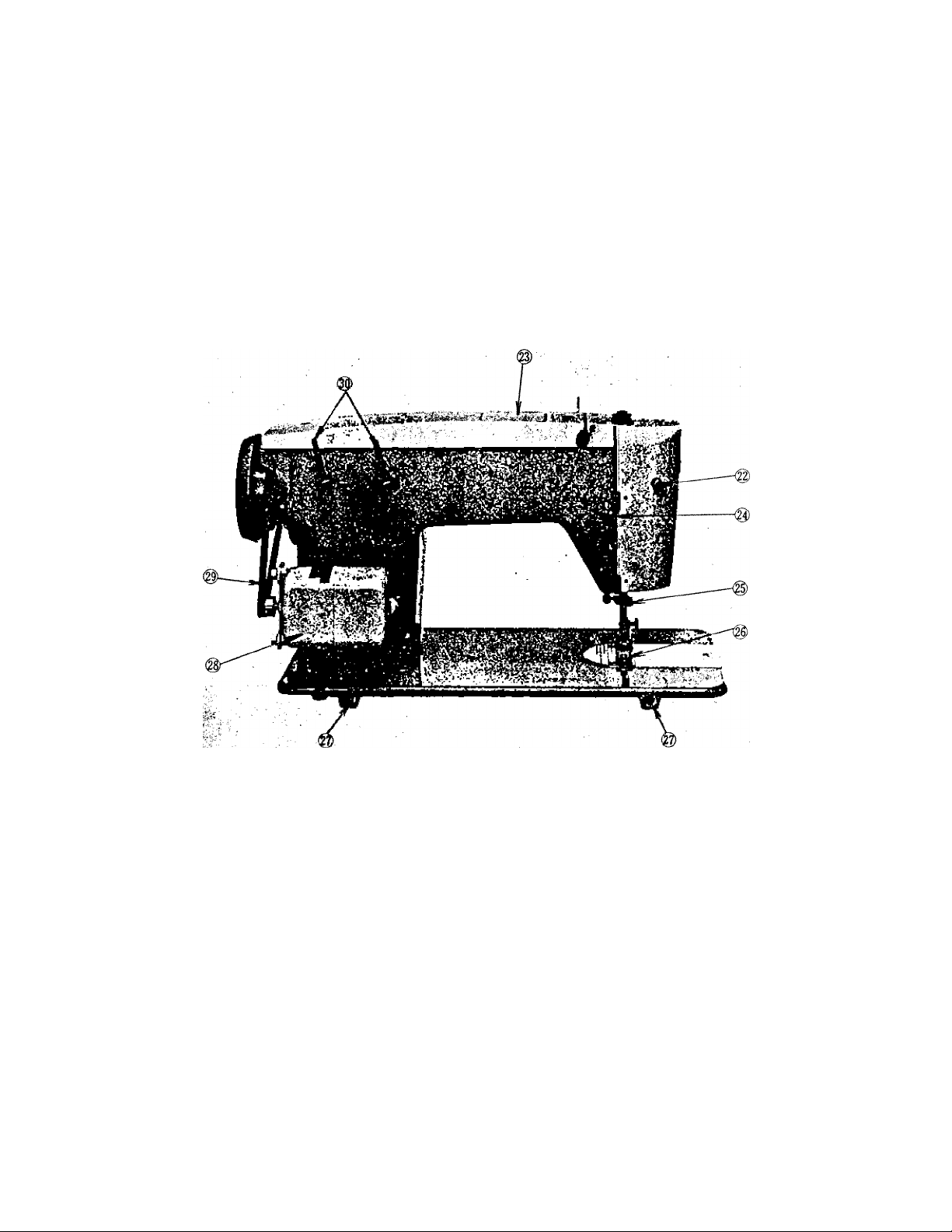
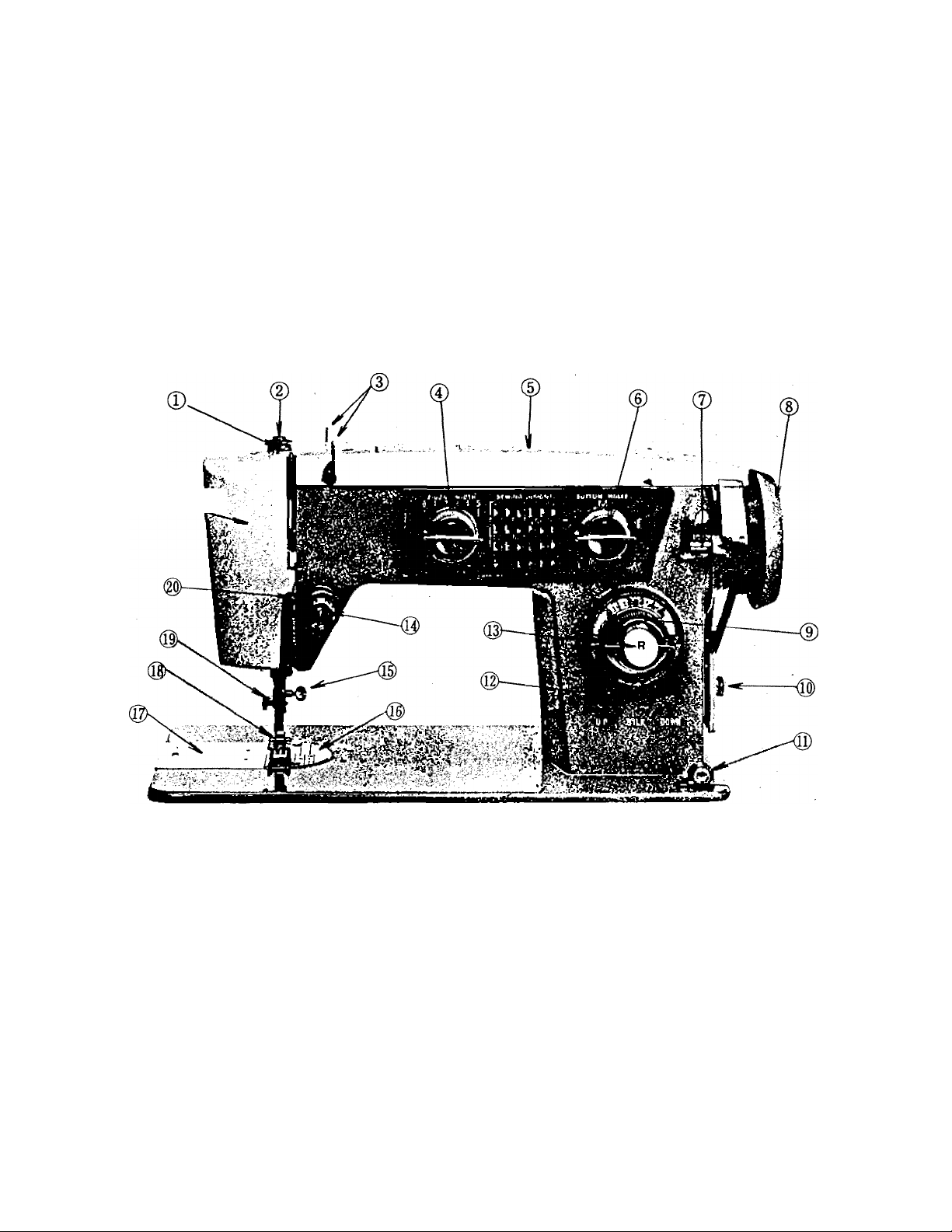
FEATURES AND PARTS
(Back View)
22. Lamp Switch
25. Thread Cutter
28. Sewing Motor
Fig. 2
23. Cam Cover Lid
26. Feed
29. Motor Belt
24. Presser Bar Lifter
27. Head Hinge Mounting Holes
3 0. Spool Pins
Page 3
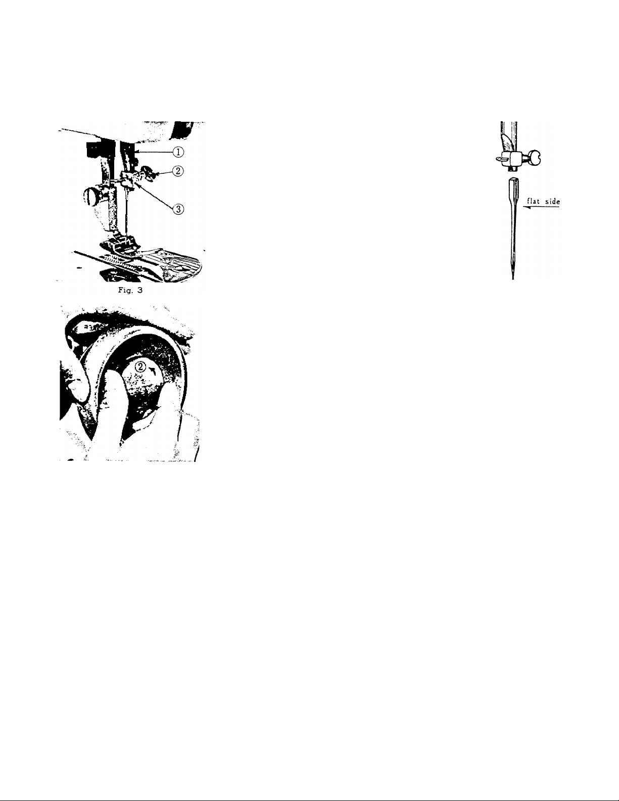
Fig. 5
INSERTING THE NEEDLE
See Fig. 3. Raise the needle bar (T) to its
highest point, turning hand wheel toward you
by hand. Then loosen the needle clamp screw
(D and the needle can be inserted into clamp (|).
Place needle (Fig. 4, flat side to right) in
the needle clamp and push it upward as far as
it will go into the needle clamp hole, tightening
the needle clamp screw securely with a screw
driver.
After changing the needle make one comp
lete revolution of the hand wheel by hand to be
sure the needle is in the correct position.
WINDING THE BOBBIN ^
Disengage the hand wheel ((T), Fig. 5) from the stitching
mechanism by turning the clutclx (|) toward you or counter
clockwise.
Raise the presser bar lifter (@, Fig. 2).
Place a spool of thread on spool pins, lead thread through
the upper thread guide, down between tension discs from left
to right, and lead thread through the tension disc at the base
of the machine. Run end of thread through a hole in the
bobbin edge and place bobbin on spindle of bobbin winder,
fitting the notch on bobbin over small pin on spindle. Push
bobbin winder latch. Hold thread end loosely and start
machine slowly.
Bobbin will stop winding v/hen it is filled. Turn clutch
away from you until sewing mechanism is again engaged so
that needle moves when you turn the hand wheel.
Break off loose thread end used to start the winding.
Page 4
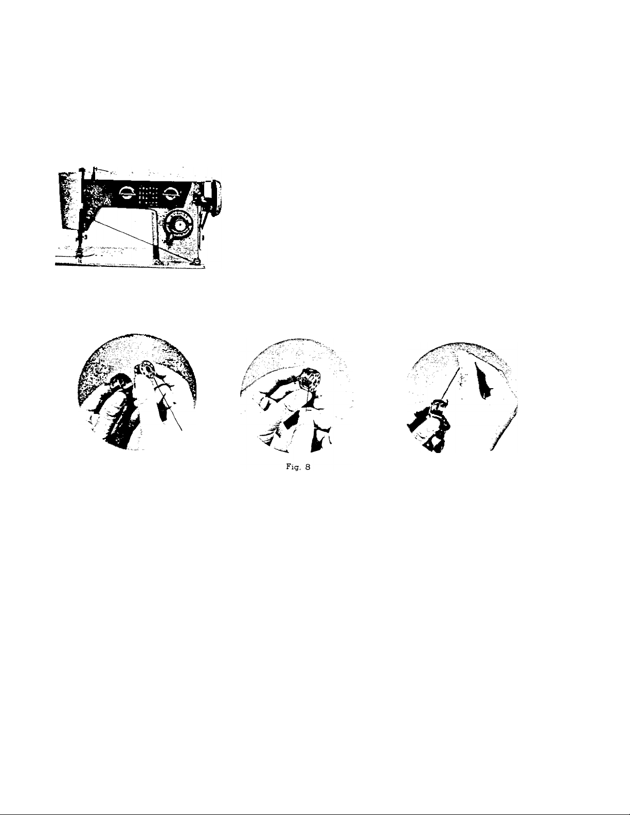
Fig. 6
THREADING THE BOBBIN CASE
Step 1 (illustrated in Fig. 7) Hold bobbin case between
thumb and forefinger of left hand, so that the slot in the
edge of the bobbin case is on top. Take the bobbin between
thumb and forefinger of right hand so that the thread on
top leads from left to right. Step 2. Insert bobbin into
bobbin case, pull the thread into the slot of the bobbin
case as shown in Fig. 8, and draw it under the tension
spring and into the fork-shaped opening of the spring as
shown in Fig. 9.
Fig. 7
Fig. 9
Page 5

PLACING BOBBIN CASE IN SHUTTLE
Open bobbin case cover plate left of the needle. (See ®, Fig. 1) See Fig. 10 Hold the
bobbin case latch, (i), between the thumb and forefinger of the left hand with at least ree
inches of thread running from the top of the bobbin case to the right Insert and center the
bobbin case on the stud of the shuttle hook (f). Be sure the bobbin case finger,
opposite the shuttle race notch, ®. Press the bobbin case ® into the shuttle as far as possible
uSl latch catches on the center post of the shuttle. THEN release the bobbin case latch,
Press bobbin case again after latch has been released to make sure the bobbin case is loc e
securely in place. Close the cover plate.
®, i
UPPER THREADING
1. Turn the hand wheel toward you to raise the takeup and needle to their highest position.
2. Place spool of thread on spool pin,
3. lead thread through hole in arm thread guide,
4. down and around one set of tension discs from right
to left,
5. into notch on the right hand side of check spring
over threaded discs,
Fig, 10
6. under thread guide bar (®, Fig. 12).
Page 6
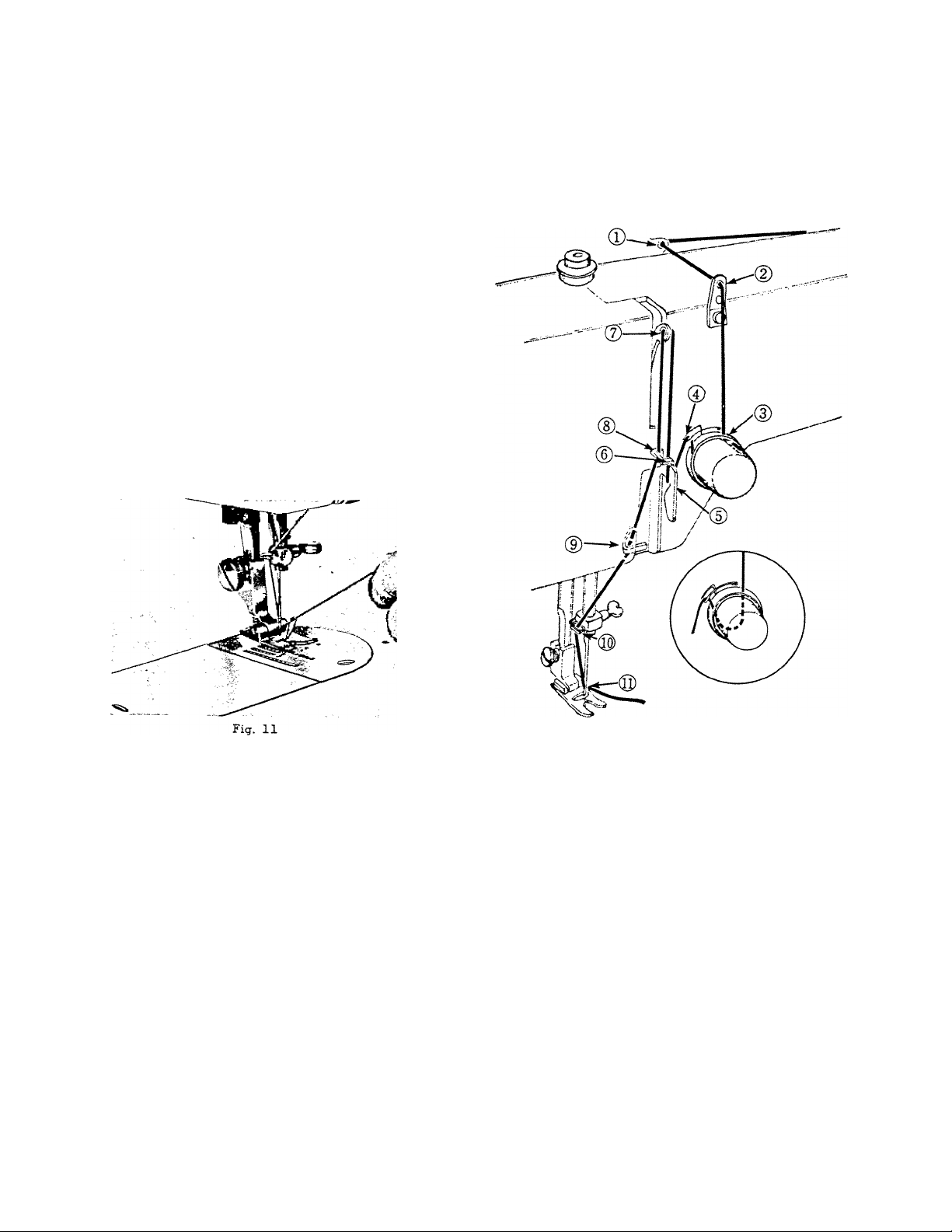
7.
Up into take-up lever from right to left.
8
.
Down through guide in thread bar.
9.
Into guide inside face.
10.
Through needle clamp guide and into
needle from left to right pulling three
or four inches of thread through needle.
Hold the end of upper thread loosely
and turn hand wheel toward you until the
needle goes all the way down and comes
back up. A loop (Fig. 11) will be formed
over the upper thread which then can be
pulled out straight. Place both thread ends
under the slot of the presser foot and draw
toward the back of the machine, leaving
both threads three or four inches long.
Fig. 12
Page 7
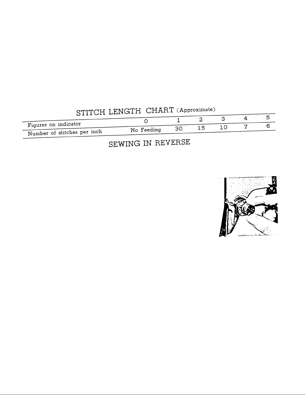
SETTING THE STITCH LENGTH
The length of the stitch is regulated by tte stitch length ^
shortest stitch and 5 left to shorten the stitch.
Th^rrer l?r slTl“orchoose^honld appear on indicator on the dial.
When yon Wish to sew bachward to tie the threads ^ hward1s“.or"
press in button R, (». Fig. 1) as far as rt will go. The machine wu
the button is held in.
adjusting THE TENSIONS
aiwnns adiust the upper tension with the presser foot down, as
the fenm^ni "eased w'k'en it is raised. To increase the tension on
te upper thread, turn dial CFlg. 13) to the right, or o ocWe. To
decrease turn to the left. The higher the number on the dial the
tighter the tension. Before adjusting lower tension be sure ¿^bin
. ■ f-Hrcarif^d orooerly When necessary to change the bobbin
machine IS threaded properly. bobbin case
tension, turn small screw (Fig. 14) on siae oi i
clockwise to tighten, counterclockwise to loosen.
Fig 13
— 10 — -
Page 8

properly balanced, a perfect stitch will be
formed with both threads interlocking in fabric
(Fig. IS).
lower thread is pulled up over the upper thread
which is lying flat on the fabric (Fig. 16).
upper thread forms loops over the lower thread
lying flat under the fabric (Fig. 17).
Fig. 14
-im
Fig. IS
ADJUSTING PRESSURE AND
FEEDING OF FABRIC
Fig. 16
When the upper and lower tensions are
When the upper tension is too tight, the
When the upper tension is too loose, the
7..—
J=J
Fig. 17
GENERAL SEWING. Usually for straight sewing and
zigzag stitching, the pressure bar cap or darner rele ,
Fig. 19 and 20, is at its lowest position and the drop
feed lever is seted to UP .
— 11 —
Fig. IS
Page 9
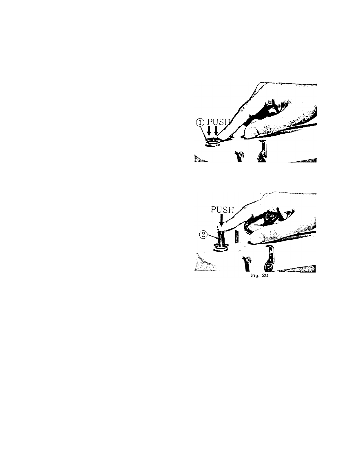
SEWING THIN OR LIGHT
WEIGHT FABRICS
When, lighter pressure is required to sew
satisfactorily on thin silk or filmy material, the
pressure cap should be about halfway down.
Release all the way by pressing the snap
lock, ((T), Fig. 19) and then press cap ((D, Fig.
20) down again to halfway spot.
DARNING AND
MONOGRAMMING
In order to move the fabric freely in any
direction for darning, mending and certain kinds
of free-hand embroidery, release the cap ((f).
Fig. 20) completely by pressing down on the
snap lock, C(T),Fig. 19). Set the lever to "DOWN",
which drops the feed well below the needle
plate. To return feed to normal, set to "UP",
push cap down (Fig. 20).
Fig, 19
12
Page 10

PREPARING TO SEW
Have take-up lever at highest point before
starting to sew. Do not try to help the feeding
by pulling the material as this may deflect the
needle and cause it to break.
NEVER run machine without material under
presser foot.
Place material and threads in position under
the presser foot and lower the presser foot.
Turn the hand wheel toward you until the
needle is at its highest point. You are now ready
to begin sewing. By having the needle at its
highest point, it is not necessary to touch the
hand wheel to start the machine. You merely
press the control. The speed of the machine is
regulated by increasing or decreasing the amount
of pressure exerted on the control.
REMOVING THE WORK
Be sure to stop the machine when the thread
take-up lever and needle bar are located at the
highest position. Now raise the presser foot and
draw the fabric back and to the left, Fig. 21
and 22, and pass the threads over the thread
cutter. Pull down slightly holding thread in both
hands, so as not to bend the needle. Leave the
ends of thread under the presser foot.
Fig. 21
Fig. 22
13
Page 11

STRAIGHT STITCHING
For straight sewing on fine included in your accessory
stitch presser foot and the straight stitch needle plat, «hitch
bolt. Both have narrow needle slots.
CWgm^the Foot ^„ew securely. To change needle
zigzag foot. Rep ace wi plnte with
plate remove screws and slide highest points,
that for straight sewing, while raising the needle bar and the pr
(1) Set the buttonholer control dial at the position mar e
,2i Set the stitch Width length, and then you can start
(3) Adjust the pitch so that you can gei yuux
sewing straight.
^ ■ „П fine fabric or very soft material, you may want to use the straight
ADJUSTING THE STITCH WIDTHS
(1) Align the indicator of buttonholer control dial.
{©, Fig. 23) with the point marked "M".
(2) Align the indicator of zigzag width control
dial ® with any desired width between 0-5.
(3) Align the stitch length indicator ® with the
stitch length you have decided to use.
Fig. 23
14
Page 12

4) Now you can start sewing zigzag as you wish.
5) Varied patterns can be made by varied operations of the stitch width control
dial 0) and the alilch length control dial ® while the machine ia in operation.
ZIGZAG STITCH PATTERNS
No. 1
1 1
2 !
3 1
i
/'vVvVvVVx
j
wimmmmEm \
1
A/jHAA/SAA ^
Patterns 1
Fig. 24
15
Stitch Length
Long
Short
Long
Short
Long and Short
(Repeat)
1 Stitch Width
; Control Dial
; Any point from 1 to 5
i
1 Gradually move from
j 0 to 5, and return to
j 0. (Repeat)
1 Any point from 1 to 5
Page 13

PLACING OF PATTERN CAMS
Open the cam cover lid (®, Fig. 25). Move zigzag
width control dial to "5^^ position. Hold the knob of
pattern cam to be place, and insert it into the axle
(D so that the groove ® of pattern cam put in the
pin d).
Then close the cam cover lid ®, and return zigzag
width control dial to "0" position.
Fig. 25
EMBROIDERING SEWING
Your machine can sew beatiful stitches with 24 pattern cams. Use zigzag presser foot and
zigzag needle plate. Replace desired pattern cam as noted on page 15.
For best results set zigzag width control dial to "0" position and stitch length near "O' as
possible.
(Pattern cams attached to the machine)
Page 14

Page 15

BLIND STITCH HEM
Blind stitch pattern can be produced by the use of change cam No. 20.
Use standard zigzag foot.
Set stitch length control dial as you wish.
Set zigzag width control dial at number 0 position.
Blind stitch hems provide a durable hem finish that is almost invisible and com
parable to hand sewing.
Prepare the garment in the scune manner as for hand hemming.
STEP 1
STEP 2
STEP 3
Fig. 27
Step 1. If hem with folded edge is used, make first fold 3/8" deep.
Step 2. Turn hem the depth desired and baste 1/4" from upper edge.
Press into place.
Step 3. Fold hem back toward right side of garment leaving 1/4" extended.
Step 4. Place garment under presser foot and sew blind hem.
18
STEP 4
Page 16

. SEWING ON BUTTONS
1.
Remove hinged presser foot and attach button sewing foot. (See Fig. 28).
2;
Set drop feed lever "DOWN” marked position.
3.
Move stitch width dial to 0 position. Place’ the button so that its left hole comes
directly under the needle, then gently lower the presser foot. Move the stitch width
dial to the right until the needle comes exactly over the right hole of the button. Turn
the hand wheel slowly by hand to be sure the needle clears both holes of the button.
4.
When needle goes into the center of each hole, nm the machine at medium speed,
making five or six stitches, stopping with the needle in the left hole.
To lock the zigzag stitch and prevent raveling, set the stitch width at 0, and take a
few stitches in the same hole. If you wish you may
place a rounded toothpick over the button between the
two holes, and sew button to fabric in regular way.
Remove the toothpick and wind thread under button,
forming a shank. Fasten.
If a four hole button is to be sewn, follow the same
procedure as above for the two hole button. Now lift
presser foot slightly and move fabric to permit stitching
the remaining two holes. Hooks, snaps, etc., are sewn
to the fabric with the same procedure as for sewing
two hole buttons. „
— 19 —
Fig, 28
Page 17

MAKING BUTTONHOLES
A buttonhole can be made in any length within the
range of limited width.
1. Replace regular presser foot with special purpose
buttonhole foot. (Fig.29].
2. Mark the beginning and end of the buttonhole on fab
ric with a basting line or tailor's chalk. Make one on
scrap fabric following directions below to be sure ma
chine adjustments are correct.
3. Set stitch width indicator at number "0" position and
stitch length indicator between "0" and "1" position.
(When the left side pitch is different from the right side pitch, adjust the pitch
by means of the stitch length control, so that pitches on both sides will be
the same.)
4. Stitch the length of the buttonhole.
5. Turn hand wheel until needle is out of fabric. Turn buttonhole control
dial to the mumber 1 position. Sew left hand side of button hole.
(Forward stitching)
6. With needle out of fabric, turn dial to the number 2 position-sew 4 or 5 stit
ches. (Bar tack)
4 Steps in
Making
Buttonhole
Fig. 30
20
Page 18

7. With needle out of the cloth, turn dial to the number 3 position-sew right hand side
of buttonhole. (Reverse stitching)
8. With needle out of the cloth, turn dial to the number 4 position-sew 4 or 5 stitches.
(Bar tack)
9. Slit the buttonhole between the two rows of stitching with the buttonhole cutter or seam
ripper. Be careful net to cut the stitching or the bar tacks.
If you plan to make buttonholes on sheer or soft material place tarlatan or paper,
which can be torn away after stitching, under the fabric.
EMBROIDERING WITH A HOOP
It is easy to follow a stamped design or to work
free hand when embroidering or monogramming.
Release the pressure from the foot by pressing down
the snap lock on the darner. Drop feed lever to "DOWN"
position. Then hang the upper end of the embroidery
spring on the needle clamp. (See Fig. 31).
Stretch the fabric in an embroidery hoop, and
place under the needle after removing the presser
foot. Set the stitch width at the size you prefer and
lower the presser bar lifter. Then operate the machine
at a rather high speed while moving the hoop slowly
with both hands. Work carefully and be sure to keep
fingers out of the needle.
"FOR BEST RESULT A WOODEN HOOP WITH TENSION ADJUSTMENT IS RECOMMENDED"
21
Page 19

THE
ADJUSTABLE CORDING AND ZIPPER FOOT
This attachment is used to make and
insert covered cording, and to sew in zip
pers. Loosen thumb screw to slide foot to
either right or left of needle. ^
CORDING. Fold bias strip of fabric
over cord. Loosen thumb screw and set
foot so needle is centered in needle hole
Machine baste cord in place (Fig. 32. 3 ).
Fig. 34
Fig. 32 ^
Fig. 33
To sew covered cord to material, reset adjustable
foot so needle stitches closer to cord, and on edge
of baric.
SEWING IN ZIPPER
Loosen thumb screw and slide loot so needle
enters center of needle hole. Guide metal of zipper
along edge of foot (Fig. 34). Stitching should be
close to zipper to allow easy opening and closing
Adjust to sew from ether right or left si e, w ic
ever is more convenient.
- 22 —
Page 20

NARROW HEMMER
With the needle
regnler presser foot vath n»r»w hemm
For a plain narrow hem, make a x/o
fold for about two inches along edge
each end of the two inch fold, slip underneatn
hemmer. Bring fold up in to the ^emme^.
draw forward to end and ¿д ends
needle. Lower presser bar liiter. (o.entiy p
of thread as you start stitching. i
Guide material slightly to right, and it will take
a double turn through scroll.
lace trimmed hem. To sew a
snd attach lace in one i“““ "bove
slot next to needleCFig. 36) S®», b“ « »bove,
auiding lace under needle and hem into scroll.
tACE EDGE WITH INVISIBLE STITCHING. Hdd
lace 1/8 inch fronj raw edge on right side ‘“b'“'
Insert both in scroll as for plain 9“««
Let hem roll over and sew m lace. Press la
flat along edge with hem turned up. . , ,
It is possible to have a little fullness in lace y
feeding it freely under scroll.
FRENCH SEAM. With right sides together, place
top piece of material 1/8 inch inside edge of lower
piece. ,,
Insert in hemmer scroll, allowing hem to ro over
and sew in top fabric, making French seam.
Fig. 35
.Fig. 36
23
Page 21

Fig. 37
QUILTING GUIDE
This guide for making parallel rows of stitching
is attached by placing the pronged holder between
the presser foot and the presser foot clamp screw
(Fig. 38). Adjust the curved bar to press lightly on
the fabric. By letting the guide ride on the first
stitching line, successive rows will . be an equal
distance apart. When the bar is attached so that the
curved part is to the right of the needle, it may also
serve as a seam width guide.
SEAM GAUGE OR CLOTH GUIDE
Use the seam gauge as a guide for straight seams and even rows of top stitching along
edges of fabric. Fasten gauge with accompanying screw in threaded hole in bed of machine
(Fig. 39) Adjust to seam width desired.
24
Page 22

CARE ÄND MAINTENANCE OF
YOUR MACHINE
HOW TO OIL YOUR MACHINE
Your machine should be oiled occasionally
to keep it operating smoothly. How often depends
on the amount of sewing you do.
Before oiling the upper part of the sewing
unit at points indicated by arrows in Fig. 40
turn hand wheel toward you until the take-up
lever is at its lowest point.
Avoid over-oiling. Only a drop is needed at
each point.
To oil parts under the bed of the machine,
tip the unit back on its hinges and apply a
drop of oil at each point indicated in Fig. 41.
To oil moving parts inside the face plate
which only rarely require oiling, open plate and
oil at spots indicatad in Fig. 42.
25
Fig. 40
Fig. 41
Page 23

Fig. 43
CLEANING AND OILING THE SHUTTLE
The stitch forming mechanism occasionally becomes
clogged with loose threads and lint.
This will interfere with the efficient operation of the
machine. Cleaning and removal of the
the performance. To remove the shuttle assembly, proce
ed as follows:
1 Turn the hand wheel until the needle reaches its
higest position. Tilt head back on its hinges.
2. Remove bobbin case (A), Fig. 43.
3'. Turn the two shuttle race cover clamps
and remove the shuttle race cover (C) and shuttle
hook (D).
4. Clean the shuttle race, the shuttle, and shuttle race
' cover by removing all threads, lint, etc.
5, Apply a drop of oil with finger tip to outer edge of
shuttle.
When the cleaning has been complied, proceed as
follows to replace the shuttle assembly.
1. Turn the hand wheel until the needle reaches its
highest position.
2. Place shuttle hook, (D), against shuttle driver and
adjust into position.
3 Replace shuttle race cover, (C), fitting pm at lower
' edae into notch, and lock into position with shuttle
race cover clamps. (B), making certain the clamps
have been snapped securely into position.
4. Put bobbin into bobbin case.
5 Put the bobbin case into the shuttle race, fitting
' tongue into notch (E) of race cover.
26
Page 24

ACCESSORIES
1. Ripper (Buttonhole Cutter)
2. Large Driver
3. Small Driver
4. Plastic Oiler (Sealed and Filled)
5. Bobbins (3)
6. Felt Washers (2)
7. Package of Needle
8. Quilting Guide
9. Cloth Guide and Thumb Screw
10. Needle Plate for Straight Stitch
11. Straight Stitching Presser Foot
12. Embroidering Spring
13. Button Sewing Foot
14. Buttonhole Foot
15. Narrow Hemmer Foot
16. Zipper Foot
Most of the above accessories are stand
ard and available in any sewing machine
store.
27
Page 25

INSTRUCTIONS FOR PORTABLE INSTALLATION
Please read these important mstruclions which were written to aid you in placing your new
sewing machine on its portable base. ■ j j in
First, remove the nail which holds the foot control mside the base to avoid damage
shipping. If a small plastic clamp is fastened to the back and not to the top of the partition at
one end of the base, remove it, too. n- u nV
After unpacking the sewing machine unit, being certain to take out the instruction bo ^
guarantee and accessory box, lay the unit face down on a table. You will see two clamp g
screws A entering head hinge holes B on the underside of the back.
On the base you will find two head hinges C which will fit into holes B, Lower the b
onto the sewing machine fitting hinges C into holes B, Tighten screws A securely with a screw
cirivsr. .
With machine in sewing position attach plastic clamp D to top of partition
provided so that it may be turned across the bed of the macfime, to hold it down, (On som
bases the clamp may be positioned in the proper spotl. , , , ...Htion of
To make the electrical connection draw the two wires throng e s o. in
the base. Plug the cord labeled "Motor" into the receptacle marked ^ ^
attached to the outer section of the base. Then insert the other cord into the Light rec p ,
Place the foot control on the floor, insert plug into a wall outlet (llO-l 15 volts) J°"
are ready to sew. But first read the instruction book to become familiar with the threading
the machine, tension adiustments and all the other features designed to make sewing a p ensure.
28
Page 26

29
Page 27

INSTRUCTIONS FOR'CABINET INSTALLATION
1. Loosen head hinge set screws until
head hinge hole is clear.
2. Tilt head hinge tongues up and back
as far as they will go.
3. Carefully slip head onto head hinges
making sure tongues are inserted as
far as they can go into head hinge
holes.
4. Allow the head to rest in its tilted
back position.
5. Tighten both set screws securely with
screw driver.
6. Plug electrical leads into sockets
located inside cabinet. Cord identified
with "motor" tag must be plugged
into socket marked "motor". Untagged
cord goes to "light" socket.
Page 28

TO ASSEMBLE LEGS ON KD CABINETS
1. Place cabinet body upside down on
smooth level surface (use packing
material as cushion to prevent marking
top.)
2. Select each leg by its corresponding
number on cabinet body corner to
insure proper match and fit.
3. sup leg into position between corner
blocks and down as far as it will
go with stud fitting into slot or hole in
metal bracket.
4. Add wing- nut and tighten securely.
5. This console is equipped with a knee
control for comfortable sewing. Lever
is adjustable and can be lowered or
raised for comfortable sewing.
Page 29

CHECK UP FOR SMOOTH SEWING
Although your sewing machine is designed for maximum efficiency, should any of the
following difficulties occur they can be remedied with minor adjustments.
Upper Thread Breaks
Be sure needle is inserted properly.
Check on correct way to thread machine.
Use correct needle size for thread.
Do not have upper tension too tight.
Lower Thread Breaks----------------—
Check correct method of threading bobbin case.
Be sure lower tension is not too tight.
Needle Breaks
Do not tug or pull on the fabric while sewing
the needle.
Be sure pressar foot is firmly attached to bar.
Skipped Stitches
Do not use a blunt or bent needle.
Insert needle correctly.
Use correct needle size for thread.
Be sure pressure on foot is sufficient when sewing heavy fabrics.
Stitches Loop
Make sure tensions are properly balanced and that machine is threaded correctly.
Machine Binds
Clean thread, dust and lint from body, shuttle and race.
If condition ontinues, it may be that the machine is gummy with oil. Apply kerosene to
oil holes, run rapidly for a while, and wipe dry. Then lubricate again with fine sewing
machine oil.
---------------
------------------
--------------as this will bend and eventually break
----------------
---------------
- 32 —
 Loading...