

Page 1

штштш
. Ч '-Ч:
''Ч:,, '5,
,v\,:'' -,'Ч;
Page 2

INDEX
Features and parts
Needle and Thread size ...
Inserting the needle .
Winding the Bobbin
Threading the Bobbin case
Placing Bobbin case in shuttle
Upper Threading
.........
Adjusting the tensions
Setting the stitch Length
Sewing in Reverse
Adjusting pressure and Feeding of Fabric
Sewing Thin or Light weight Fabric
Darning and monngramming
Straignt stitching ..
Zgzag Stitching
.......................
PLacing of pattern cam
for Embroidry Sewing
Sewing Pattern
...............
Page
.....
.....
..... 5
.... 7
.... 7
.... 8
.... 9
10
10
,. 11
.. 12
Page
2
3
4
5
6
7
Blind Stiching
Sewing on Buttons
Making Buttonholes 1 s.
Embroidering with a hoop
The Adjustable cording and zipper Foot
Cording . .
Sewing in zipper
Narrow Hemmer ....
Quilting Guide. .
Seam Gauge or cloth Guide
Care and maintenance of your manhitip
Cleaning and Oiling Hook Assembly
Check up for Smooth Sewing
Accessories ...
Instructions for Portable Installation
..........
Instructions for Cabinet Installation
To Assemble Legs on KD Cabinets
~16
. 17
17
18
19
19
20
21
22
2.3
24~25
26
27
Page 3
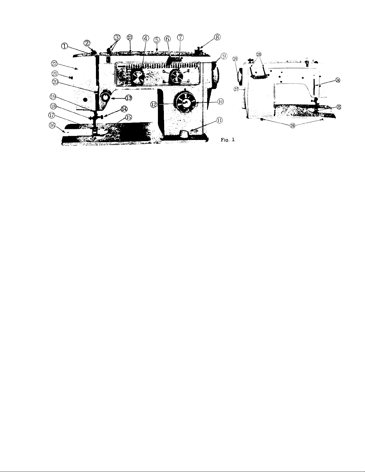
FEATURES AND PARTS
1. Thread Take-up Lever
2. Pressure Release CDarning)
3. Top Plate Thread Guides
4. Zigzag width control Dial
5. Top Plate
6. Needle Positioning Lever
7. Buttonholer Control Dial
8. Bobbin winder Spindle
9. Hand wheel
10. Stitch Length Control Dial
11. Drop Feed Dial
12. Push Button Reverse
13. Tension Regulator Dial
14. Needle Clamp Screw
15. Needle Plate
16. Bobbin Cover Plate
17. Pressure Foot
18. Pressure Foot thumb screw
19. Thread cutter
20. Thread Bar and Guide
21. Lamp Switch
22. Face Plate
23. Cam Cover
24. Pressure Bar Lifter
25. Feed
26. Head Hinge Mounting Holes
27. Motor Belt Cover
28. Spool Pins
29. Clutch Release
Page 4

NEEDLE AND
THREAD
SIZE
Fabric
Extremely heavy
tarpaulin, sacking.
canvas, duck, ete.
Heavy upholstery
fabric, ticking.
denim, leatherette
Medium heavy drapery
fabric, velveteen.
suiting, felt, terry, etc.
Medium broadcloth,
percale, gingham, linen.
chintz, taffeta, sheer
wool, shantung, etc.
Sheer voile, lawn.
dimity, crepe,
handkerchief linen.
plastic film, etc.
Very sheer chiffon.
batiste, lace, organdy.
ninon, net, marquisett, etc.
15x1
Needle
No.
Machine
Stitches
Per Inch
6
19
18
16
14
11
&
Ball Point
r^eedie CPlastic film)
9
&
BaU Point
Needle
to
8
to
10
10
to
12
12
to
14
14
to
16
8 to 10
16
to
20
Cotton
Thread
10
8
to
30
30
to
40
40
to
60
60
to
80
80
to
100
100
to
150
Mercerized
Thread
Heavy Duty
Heavy Duty
Heavy Duty
50
50
50
Silk
or
Nylon
E
Twist
D
Twist
c
Twist
A&B
Twist
O
Twist
OO&OOO
Twist
Page 5
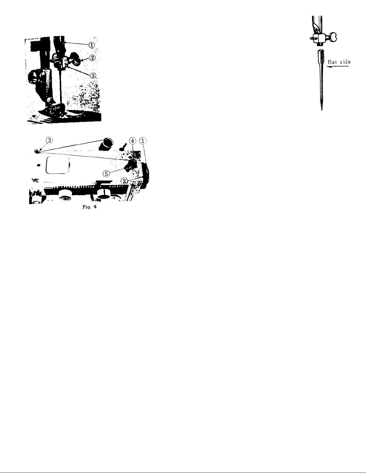
INSERTING THE NEEDLE
See Fig. 2. Raise the needle bar ® to its highest point, turning
hand wheel toward you by hand. Then loosen the needle clamp
screw (D and the needle can be inserted into clamp
Place needle (Fig.3, FLAT SIED TO RIGHT) in the needle ckmp
and push it upward as far as it will go into the needle clamp ho e,
tightening the needle clamp screw securely with a screw driver.
After changing the needle, make one complete revolution of the
hand wheel by hand to be sure the needle is in the correct position.
®.
Fig. 3
Fig. 2
WINDING THE BOBBIN
Disenaaae the hand wheel C®, Fig. 4) from the stitching
Disengag _i„trh
mechanism by turnmg the clutch CU< y lead
oloctwi^. ..pool of to...! »“ol
thread around one set of arm thread guide (®, Fig. 4). Run en
thread through a hole in the bobbin edge and place
spindle of bobbin winder (®, Fig. 4) fitting the ^°tch^ bobbm
over small pin on spindle. Push bobbin ^^wly
against bobbin. Hold thread end loosely and start machine slo y
Bobbin will stop winding when it is filled.
Tu^ clutch away To reengage stitching mechanism turn clutch
(®,Fig.4) clockwise.
C(i)
Fig 4) toward you or counter
Page 6
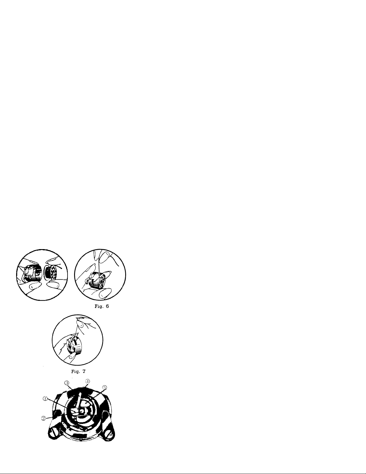
Fig. 3
Fig. 8
THREADING THE BOBBIN CASE
Step 1 (illustrated in Fig. 5) Hold bobbin case between thumb
and forefinger of left hand, so that the slot in the edge of the
bobbin case is on top. Take the bobbin between thumb and
forefinger of right hand so that the thread on top leads from left
to right. Step 2. Insert bobbin into bobbin case, pull the thread
into the slot of the bobbin case as shown in Fig. 6, and draw it
under the Tension spring and into the fork-shaped opening of the
spring as shown in Fig. 7.
PLACING BOBBIN CASE IN SHUTTLE
Open bobbin case cover plate left of the needle. (@, Fig. 1)
See Fig. 8. Hold the bobbin case latch, ®, between the thumb and
forefinger of the left hand with at least three inches of thread
running from the top of the bobbin case to the right. Insert and
center the bobbin case on the stud of the shuttle hook ®. Be sure
the bobbin case finger (S) is inside the shuttle race notch ®.
Press the bobbin case ® into the shuttle as far as possible until
latch catches on the center post of the shuttle. Then release the
bobbin case latch ®. Press bobbin case again after latch has been
released to make sure the bobbin case is locked securely in place.
Close the cover plate.
Page 7
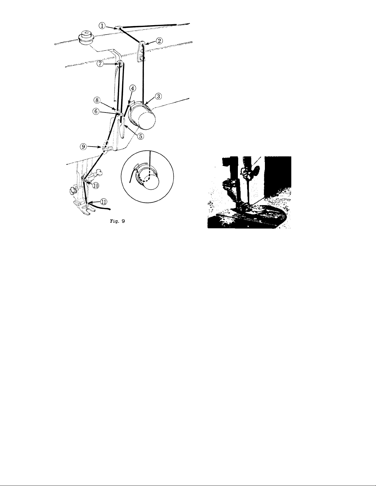
Turn hand wheel toward you to raise the
UPPER THREADING
take-up lever and needle to their highest position.
Place spool of thread on spool pin and lead
thread through top plate thread guide® and®.
Down and between tension discs® from right
to left.
Up and over the tension spring® then down
under the thread bar®
Up though thread bar guide® and into take-up
leverr® from right to left.
Down through thread bar guide® again and
into face plate guide® and needle clamp guide®.
Thread needle from left to right pulling three
to four inches of thread through needle.
Hold the end of the upper thread loosey and
turn hand wheel toward you until the needle goes
all the way down and comes back up bringing with
it the bottom or bobbin case thread.
Place both threads
(upper and lower)
imder the slot of the
Presser foot and place
toward the back of the
machine, leaving both
threads three to four
inches long.
Fig, 10
Page 8
Normol tension Tijht tension
Fig. 11
ADJUSTING THE TENSIONS
A correct stitch can be obtained by varying the tension on the
needle thread. To adjust the tension of the needle thread, Lower
the pressure foot.
Adjust the tension regulator as the case demand, by reffernng
to iUustration. (Fig.ll) The quality of sewing depends on the
tension of thread. Therefore, it is necessary for the user to
become fully familiar with the correct tensions through practice.
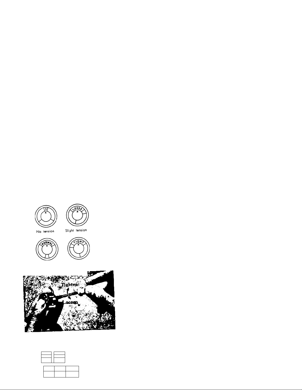
Before adjusting lower tension be sure that the machme is
threaded properly. When necessary to change the bobbm te^n,
turn small screw (Fig. 12) on side of the bobbin case clockwise
to tighten, counter-clockwise to loosen.
When the upper and lower tensions are properly balanced,
perfect stitch will be formed with both threads interlocking in
fabric (Fig. 13). , , . n j
When the upper tension is too tight, thrLbric^^g
up over the upper thread which is lymg flat on the fabric C^g.
ph ..1
■ M.
Fig. 12
,
"-'v
g Fig. 14
S Fig. 15
14).
13
When the upper tension is too loose, the upper thread forms
loops over the lower thread lying flat under the fabric (Fig. 15).
Page 9

-:--r
Fig 16
SETTING THE STITCH LENGTH
The length of the stitch is regulated by the stitch length control
dial C@, Fig. 1) Near 0 is the shortest stitch and 5 is the longest.
But the control may be set at any spot between marking for a
variety of lengths. Turn the control dial to the right to lengthen
and to the left to shorten the stitch.
STITCH LENGTH CHART (Approximate)
Figures on indicator
Number of stitches par inch
0 1 2 3 4 5
No Feeding 30 15 10 7 6
SEWING IN REVERSE
When you wish to sew backward to tie the threads at the
beginning or end of a seam, press in the push button (@, Fig. 1)
as far as it will go. The machine will sew backward as long as the
button is held in.
ADJUSTING PRESSURE AND FEEDING
OF FABRIC
GENERAL SEWING. For normal straight stich and zigzag
stitching, the pressure bar cap or darner release, Fig. 17 and
18 is at its lowest position and the drop feed dial Fig. 16 is
set to "UP" position.
Page 10

SEWING THIN OR LIGHT WEIGHT FABRICS
When lighter pressure is required to sew satisfactorily on thin
silk or filmy material, the pressure cap should be about halfway
down.
Release all the way by pressing the snap look, C®, Fig. 17)
and then press cap C®, Fig. 18) down again to halfway spot.
DARNING AND MONOGRAMMING
In order to move the fabric freely in any direction for darning,
mending and certain kinds of free-hand embroidery, release the
cap C®, Fig, 18) completely by pressing down on the snap lock,
C®, Fig. 17). Set the drop feed dial (Fig.l6) to "DOWN." which
drops the feed well below the needle plate. To return feed to
normal, set to "UP", push cap down (Fig. 18).
Page 11

10
1» /
Fig. 19
STRAIGHT STITCHING
® Set needle position lever to L position.
(D Set Buttonhole disc ((D) indicator on M position.
(D Set zigzag width contrl dial ® at "O" Position. _ „
® Select desired stitch length by turning stitch length dial ® 0 5^
For more precise straight stitching on special fabrics this machme
eqX^rwith a straight stitch needle plate (#10 page23) and straight
stUch^resser foot (#11,Page 23) please note both accessories have
a small round hole instead of the wide slot as used for zigzag
The crosswise slot-needle plate and prsser foot-allow t e ®
sideways (zigzag) while moving up and down. A cam is not required
for straight stitching. , , .
To change needle plate, remove the setting screws on the plate.
replace with straight stitch needle plate and tighten screws securely.
When straight sewing with the regular zigzag needle plate and^^^^^^^
presser foot the needle can also be positioned in the M (middle)
piosition.
ZIGZAG STITCHING
® Use regular zigzag presser foot and needle plate.
(2) Cams are not required for normal zigzag sewmg.
® Set needle position lever to L, M or R position, preferably L.
® Set buttonhole dial to M position on panel.
® Select width desired from 0 to 5 on zigzag width knob.
® Length of zigzag stitch can be varied by increasmg the size of
©M^tSf virinces are possible by changing needle position,
stitch widths and stitch lengths.
Page 12

4ft:
Pattern Cam and box
s
©
PLACING OF PATTERN CAM FOR
EMBROIDERY SEWING
1) Use regular zigzag pressure
foot and needle plate.
2) Open the cam cover lid ®.
Fig. 20.
3) Set buttonhole dial to M
position on panel.
4) Turn zigzagicontrol diallto
position 5 this permits the
insertion of cam on to the
spindle ®. Revolve cam, pressing
down slightly tmtil hole in bottom surface is fitted over pin
5) Close cam cover lid and return zigzag Control dial to "0"
position.
6) Set stitch length between O and 1 for effect desired the shorter
the stitch length the greater the density of pattern sewn.
Needle position can be set at left (L), middle (M) or right (R).
Each position alters the basic stitching line and designs sewn.
IMPORTANT When using Cam |20 (blind hem cam) for blind
hemming, set needle position lever to "R" position.
Fig. 20
®,
11
Page 13

12
SEWING PATTERNS
Page 14

STEP 1
BLIND STITCHING
1. Use regttlar zigzag pressure foot and needle plate.
2. Insert Cam No. 20 into tlie machine.
3. Set needle position lever to "R" position.
STEP 2
4. Select stitching length desired.
5. Buttonhole dial must be set on "M" position.
Blind stitch hems provide a durable hem finish that is almost
invisible and comparable to hand sewing.
Prepare the garment in the same manner as for hand hemming.
Step 1. If hem with folded edge is used, make first fold 3/8
deep.
Step 2. Turn hem the depth desired and baste 1/4 from upper
edge. Press into place.
Step 3. Fold hem back toward right side of garment leavmg 1/4"
extended.
Step 4. Place garment under pressure foot and sew blind hem.
Fig. 21
Page 15

14
Fig. 22
SEWING ON BUTTONS
1. Use button sewing foot and zigzag needle plate.
2. Set drop feed dial to "EXDWN" position.
3. Set the needle positioning lever to "L" position.
4. Move zigzag width control dial to "0" position. Place the button
so that its left hole comes directly under the needle, then gently
lower the presser foot. Move the zigzag width control dial to the
right until the needle comes exactly over the right hole of the
button. Turn the hand wheel slowly by hand to be sure the needle
clears both holes of the button.
5. When needle goes into the center of each hole, run the machine
at medium speed, making five or six stitches, stopping with the
needle in the left hole.
6. To lock the zigzag stitch and prevent ravelling, set the zigzag
width control dial at 0, and take a few stitches in the same
hole. If you wish, you may place a roimded toothpick over
the button between the two holes, and sew button to fabric in
regular way. Remove the toothpick and wind thread under
button, forming a shank. Fasten. ,
If a four hole button is to be sewn, follow the same procedure
as above for the two hole button. Now lift pressure foot slightly
and move fabric to permit stitching the remaining two holes.
Hooks, snaj», etc. are sewn to the fabric with the same proce
dure as for sewing two hole buttons.
Page 16

MAKING BUTTONHOLES
A buttonhole can be made in any length within the range of
limited width.
1. Use special purpose buttonhole foot (Fig. 23) an igzag
needle plate.
2. Mark the beginning and end of the buttonhole on fabric with a
basting line or tailor's chalk. Make one on scrap fabric followmg
directions below to be sure machine adjustments are correct.
i-
3. Set the needle positioning lever at "L" position, and zigzag width
indicator at "0" position and stitch length indicator between
-Cam
Fig. 23
4 Steps in
Making
Buttonhole
Fig. 24
"0" and "1" position. , , , ,
4 Turn hand wheel imtil needle is out of fabric. Turn ut on o e
control dial to No. 1 position. Sew left hand side of buttonho e.
(Forward stitching)
5. With needle out of fabric, turn dial to No. 2 position an se
4 or 5 stitches. (Bar tack)
6. Wltk «e«iU 0.1 of tho Olotl., tom di.l to No. 3 po.ltio. ood
aew right hand aide of buttonhole. (Reverae stitching)
7. With needle out of the cloth, turn dial to No. 4 position and
sew 4 or 5 stitches. (Bar tack)
Page 17

8. Slit the buttonhole between the two rows of stitching with
the buttonhole cutter or seam ripper. Be careful not to cut
the stitching or the bar tacks.
If you plan to make buttonholes on sheer or soft material,
place tarlatan or paper, which can be torn away after
stitching under the fabric.
NOTE; When the left side pitch is different from the right side
pitch, adjust the pitch by means of the stitch length
control, so that pitches on both sides will be the same.
EMBROIDERING WITH A HOOP
^ It is easy to follow a stamped design or to work free
hand when embroidering or monogramming. Release the
pressure from the foot by pressing down the snap lock on the
darner. Drop feed dial to "DOWN" position. Then hang the
upper end of the embroidery spring on the needle clamp.
(See Fig. 25).
Stretch the fabric in an embroidery hoop, and place under
the needle after removing the pressure foot. Set the zigzag width
at the size you prefer and lower the pressure bar lifter. Then
operate the machine at a rather high speed while moving the
hoop slowly with both hands. Work carefully and be sure to
keep fingers out of the needle.
FOR BEST RESULT A WOODEN HOOP WITH TENSION
ADJUSTMENT IS RECOMMENDED"
Page 18

THE ADJUSTABLE CORDING AND ZIPPER FOOT
This attachment is used to make and insert
covered cording, and to sew in zippers.
Loosen thumb screw (Fig. 26) to slide foot
to either right or left of needle.
CORDING. Fold bias strip of fabric over
cord. Loosen thumb screw and set foot so
needle is centered in needle hole. Machine
baste cord in place (Fig. 27. ).
To sew covered cord to material, reset adjustable foot so
needle stitches closer to cord and on edge of base fabric.
SEWING IN ZIPPER
Loosen thumb screw and slide foot so needle enters center of
needle hole. Guide metal of zipper along edge of foot (Fig. 28).
17
Fig. 28
Stitching should be close to zipper to allow easy opening and
closing. Adjust to sew from either right or left side, whichever is
more convenient.
Page 19

18
NARROW HEMMER
With the needle at its highest position, replace regular
presser foot with narrow hemmer (Fig. 29) For a plain
narrow hem, make a 1/8 inch double fold for about two
inches along edge of fabric. Hold each end of the two
inch fold, slip undereneath hemmer. Bring fold up into
the scroll of hemmer, draw forward to end and fasten with
point of needle. Lower presser bar lifter. Gently pull ends
of thread as you start stitching.
Guide material slightly to right, and it will take a
double turn through scroll.
Trimmed Hem To sew a narrow hem and attach
lace in one stitching, insert lace in the slot next to needle
(Fig. 30). Sew hem as above, guiding lace under needle
and hem into scroll.
Lace Edge with Invisible Stitching Hold lace 1/8 inch
from raw edge on right side of fabric. Insert both inscroll
as for plain narrow hem (Fig.31). Let hem roll over and
sew in lace, press lace out flat along edge with hem
turned up.
It is possidle to have a little fullness in lace by feeding
it freely under scroll.
French Seam With right sides together, place top piece
of material 1/8 inch inside edge of lower piece.
Insert in hemmer scroll, allowing hem to roll over and
sew in too fabric, makincr French seam.
Fig. 29
Fig. 30
Page 20

QUILTING GUIDE
Tlus guide for making parallel rows of stltcliing is
attached by placing the pronged holder between the pressure
foot and the pressure foot clamp screw (Fig. 32). Adjust the
curved bar to press lightly on the fabric. By letting the guide
ride on the first stitching line, successive rows will be an
equal distance apart. When the bar is attached so that the
curved part is to the right of the needle, it may also serve as
a seam width guide.
SEAM GAUGE OR CLOTH GUIDE
Ig
Fig. 32
Use the seam gauge as a guide for straight seams and
even rows of top stitching along edges of fabric.
Fasten gauge with accompanying screw in threaded hole in
bed of machine (Fig. 33). Adjust to seam width desired.
Page 21

20
CARE AND MAINTENANCE
OF YOUR MACHINE
HOW TO OIL YOUR MACHINE
Your machine should be oiled occasionaUy to
keep it operating smoothly. How often depends
Fig. 34
Fig. 35
on the amount of sewing you do.
Before oiling the upper part of the sewing
unit at points indicated by arrows in Fig. 34 turn
hand wheel toward you until the take-up lever is
at its lowest point.
Avoid over-oiling. Only a drop is needed at
each point.
To oil parts under the bed of the machine,
tip the unit back on its hinges and apply a drop
of oil at each point indicated in Fig. 35.
To oil moving parts inside the face plate
which only rarely require oiling, open plate and
oil at spots indicatad in Fig. 36.
Page 22

Fig. 36
21
CLEANING AND OILING HOOK ASSEMBIY
If machine binds, clean hook assembly as follows.
1. With take-up lever in highest position, tilt head back on
hinges and remove bobbin case.
CASE
LATCH
2. Turn clamps outward and remove race cover.
3. Remove hook.
4. Clean thread and lint from all parts, including race.
5. Run a drop of oil along rim of hook.
6. Replace hook, then race cover. Snap clamps into place.
7. Grasp threaded bobbin case by latch and replace, fitting
tongue into notch of race cover.
Page 23

22
CHECK UP FOR SMOOTH SEWING
Although your sewing machine is designed for maximum efficiency should any of the following
difficulties occur they can be remedied with minor adjustments.
Upper Thread Breaks
Be sure needle is inserted properly.
Check on correct way to thread machine.
Use correct needle size for thread.
Do not have upper tension too tight.
Lower Thread Breaks-------------
Check correct method of threading bobbin case.
Be sure lower tension is not too tight.
Needle Breaks
Do not tug or pull on the fabric while sewing as this will bend and eventually break the needle.
Be sure pressure foot is firmly attached to bar.
Skipped Stitches
Do not use a blunt or bent needle.
Insert needle correctly.
Use correct needle size for thread.
Be sure pressure on foot is sufficient when sewing heavy fabrics.
Stitches Loop
Make sure tetiginug are properly balanced and that machine is threaded, correctly.
Machine Binds------------
Clean thread, dust and lint from body, shuttle and rece.
If condition ontinues, it may be that the machine is gummy with oil. Apply kerosene to oil holes,
run rapidly for a while, and wipe dry. Then lubricate again with fine sewing machine oil.
------------
-------------
------------
------------
Page 24

accessories
1. Ripper (Buttonliole Cutter)
2. Small Driver
3. Large Driver
4-, Plastic Oiler (Sealed and. Filled)
5. Bobbins
6. Felts for Spool pin
7. Needles (Regular and Ball Point)
8. Quilting Guide
9. Clotb Guide and Thumb Screw
10. Needle plate for Straight Stitch
11. Straight Stitch Presser Foot
12. Embroidery Spring
13. Button Sewing Foot
14. Buttonhole Foot (Plastic)
15. Narrow Hemmer Foot
16. Zipper Foot
17. Roller foot
The roller foot and the ball point
needles in your accessory box will
help you in sewing on the new
synthetic materials now on the
market.
23
Page 25

24
INSTRUCTIONS FOR PORTABLE INSTALLATION
Please read these imporlarrt instructions which were wrrtten to aid you in placing your new
^lfUr".i”fi"iwtg"rnTchi^^ en.t,be.ng certain to tahe out the instruct.on booh,
JrZJL accessory bon, lay the unrt lace down on a table. You will see two clanrp.ng
screws A entering head hinge holes B on the underside of the back. ,, K =
On the base you will find two head hinges C which will fit into holes B. Lower the base
onto the sewing machine fitting hinges C into holes B. Tighten screws A securely with a screw
‘'with machine in sewing position attach plastic clamp D to top of partition with screw
prrvlded so that it may be turned across the bed of the machine, to hold it down. (On some
Vyflqes the clamp may be positioned in the proper spot).
To make the elecLcal connection draw the two wires through the slot rn the padition of
the base. Plug the cord labeled "Motor" into the receptacle marked ~
attached to the outer section of the base. Then insert the other cord into the Lrgh ecep ^
Place the foot control on the floor, insert plug into a wall outlet (110-115 vol s) and y
arfready to sew. But first read the instruction book to become familiar with the threading of
the machine, tension adjustments and all the other features designed to make sewing a pleasur .
Page 26

25
Page 27

BACK OFF
SET SCREW
TO CLEAR
HINGE HOLE
X
HEAD HINGE SET
SCREWS
LIFT FLAP
TO LOWER
HEAD INTO
CABINET
INSTRUCTIONS FOR CABINET INSTALLATION
1. Loosen head hinge set screws until
head hinge hole is clear.
2. Tilt head hinge tongues up and back
as far as they will go.
3. Carefully slip head onto head hinges
making sure tongues are inserted as
HEAD HINGE
HOLES
HEAD HINGES
HINT; STRETCH
A RUBBER BAND
ACROSS THE TWO
HINGES TO HELP
HOLD THEM UP.
RIGHT WHILE
MOUNTING THE
SEWING HEAD.
far as they can go into head hinge
holes.
4. Allow the head to rest in its tilted
back position.
5. Tighten both set screws securely with
screw driver.
6. Plug electrical leads into sockets
located inside cabinet. Cord identified
with "motor" tag must be plugged
into socket marked "motor". Untagged
cord goes to "light" socket.
7. If your machine begins to run automatically
without the use of the knee, control, this
indicates that the motor plug and light
plug are in the wrong sockets and should
be reversed.
Page 28

TO ASSEMBLE LEGS ON KD CABINETS
1. Place cabinet body upside down on
smooth level surface (use packing
material as cushion to prevent marking
top.)
2. Select each leg by its corresponding
number on cabinet body corner to
insure proper match and fit.
3. Slip leg into position between corner
blocks and down as far as it will
go with stud fitting into slot or hole in
metal bracket.
27
4. Add wing nut and tighten securely.
 Loading...