

Page 1

R, F.
BOOK 10
DIRECTIONS
For Using the
White Rotary Sewing
Machine
MANUFACTURED BY
White Sewing Machine Company
Cleveland, Ohio, U. S. A.
Page 2

When writing for information regarding parts or anything per
taining to your machine, be sure to mention style of machine,
whether Vibrator or Rotary shuttle, also give the plate No. which is
stamped on bed of machine at foot of arm.
By giving full information it will save time and expense.
Instructions for operating the WHITE supplied in English, Ger
man, Spanish, Portuguese. French, Bohemian, Swedish, Danish, Dutch.
Italian. Polish, Finnish, Hungarian and Russian.
Page 3

iNSTRUCTiONS
FOR USING THE
White Rotary Sewing Machine
MANUFACTURED BY
White Sewing Machine Company
Cleveland, Ohio, U. S. A.
Never run Machine ivitJi needle threaded toithout goods under
p7'esser-foot. Run Machine so that upper side of hand tvheel moves
from you,
TO SET NEEDLE
Raise the lieedle-bar to its highest point; loosen the thumb-screw
and press it to the left to permit the shank of the needle to pass up
between the clamp and needle-bar as far a sit will go, flat side to the
RIGHT—the NEEDLE being flatened on one side so it will set itself per
fectly, then fasten securely by tightening thumb-screw.
To avoid loosening of the needle, ahoays use a screw driver to
fasten the same, the needle nut bemg slotted for that purpose.
The needle, when descending, should pass central in the needle
hole from front to rear, but close to the right side of the hole, as it
prevents the needle from glancing into the race and being caught by
the shuttle.
NEEDLES AND THREAD TO BE USED
The MOST IMPORTANT consideration is to buy and use perfect nee
dles—not bent, nor blunt points.
When ordering needles for this machine, be sure to ask for the
genuine White Rotary flat shank needles which are stamped on the
shank “White F. R.” Imitation or “just as good” needles will cause
trouble. Get the genuine White.
Cut of White Rotary flat shank needle
showing exact length.
iize of the needle sh
and both be suitable to the material sewed. Use as fine a needle as
will permit the thread to pass freely through the eye.
The following index will show the size of needle, thread and silk
to be used.
For colored thread use needles one size larger than given in in
dex above.
г'П'Г'глАт 'TKT3F
150 to
300
150
90 to
70 to
50 to
30 to
. 20 to
90
70
50
30
SILK THREAD
000
00
0
A & в
c
D
NO. OF NEEDI '
00
0
1
2
8
4
Page 4
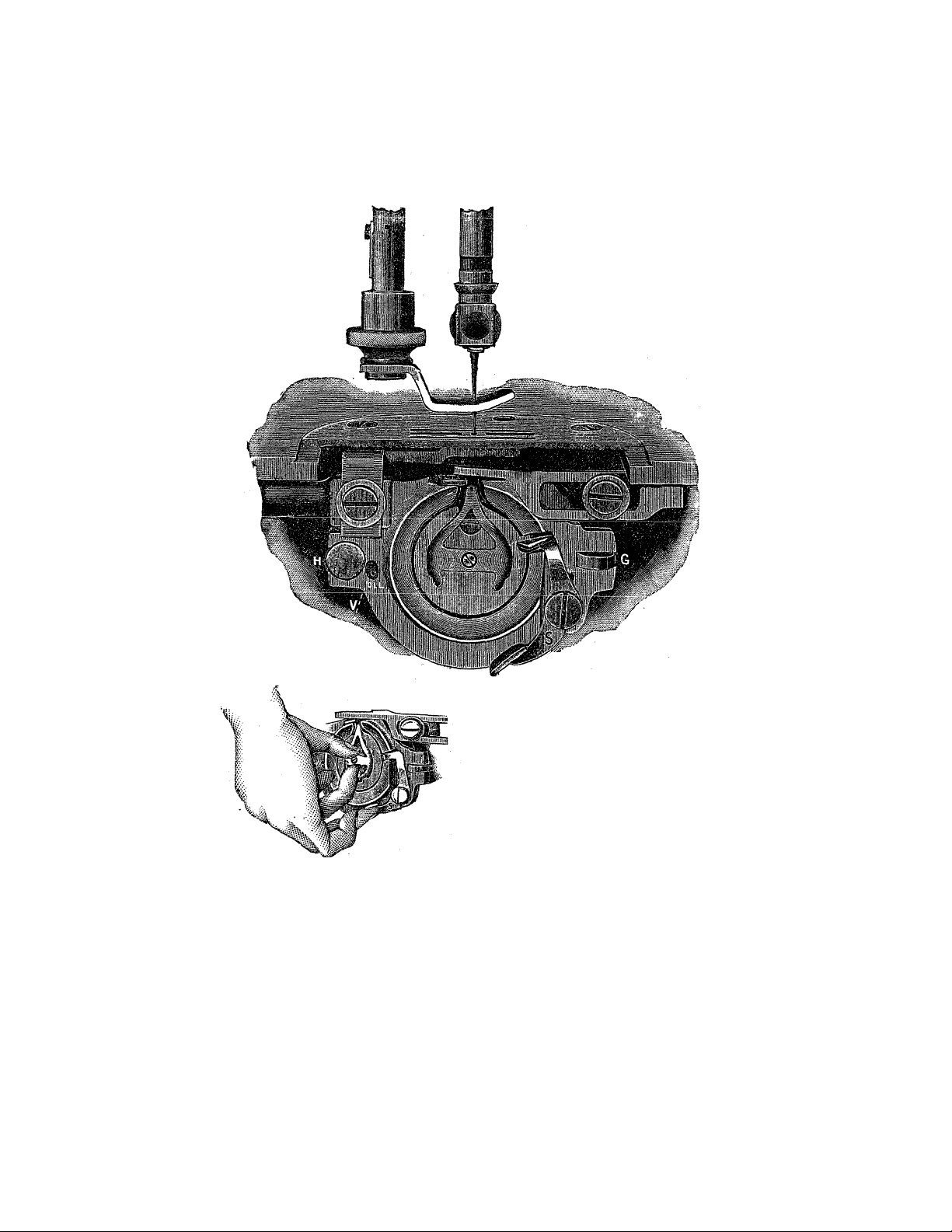
TO REMOVE BOBBIN CASE
FROM SHUTTLE
Raise the take-up to its highest
point. With the thumb and second
finger of left hand clasp bobbin case
as shown in cut, then lift latch S
with the third finger, when bobbin
case may be readily withdrawn
from shuttle
TO REMOVE SHUTTLE FROM SHUTTLE RACE
First remove the bobbin case. Turn the machine back on its
hinges, then turn the machine in the same direction as in sewing
until the point of the needle just enters the needle plate hole; push
on rear end of latch G and at the same time pull shuttle race cover
away from shuttle and toward latch G from under pin H; the shut
tle can now be removed.
When shuttle has been removed from race be sure to clean both,
and oil the race slightly before replacing. Occasionally oil slightly
in hole on race cap marked V above and pin W in shuttle, see page
5 fig. 9. 4
F. See page 5,
Page 5
4 •• •e4eewe* *i&
lU KtrL-AUli I Mt SMU l i Lt
Turn the machine in direction for sewing until the point of the
needle just enters the needle plate hole; take the shuttle by the
center pin W with the left hand and place it in the race, so that
point of shuttle will be fi’om you and over arrow on thread cast off,
so that the holes in the shuttle will drop on to driving pins in race,
then replace the shuttle race cover.
DO NOT FORCE the shuttle into race. It will enter readily
wllPTI in -nnAnAT* nn.dlfin'n
' ' t' * -
---
-
Should the machine at any time act badly in sewing or running
it would be well to remove shuttle and clean it and the race, which
is but a moment’s work.
To replace the bobbin case, it need not be held as when remov
ing, but simply slip it on the pin in shuttle, with the tension project
ing upward, and push it into shuttle as far as it will go, when the
spring latch will pass over and retain it in that position.
The thread should be allowed to project about one inch from
TO WIND BOBBIN ^
Place spool on spool pin, pass the thread down ^
through the rear hole in arm of cover plate, then to
_
____3 _
_______
_____
______
uie leiir uuuer aiiu over tue ¿inu uuwii uixougu i.xuuu
.¿.г.J
__________
__
hole. Put the end of thread through hole U in bobbin S
from inside out, place bobbin on
bobbin winder spindle, raise winder
so belt will drive it, loosen thumb % Bobwn
screw in hand wheel, run the machine as in sewing,
holding on to the end of thread until winding is
started, then break off thread and finish winding.
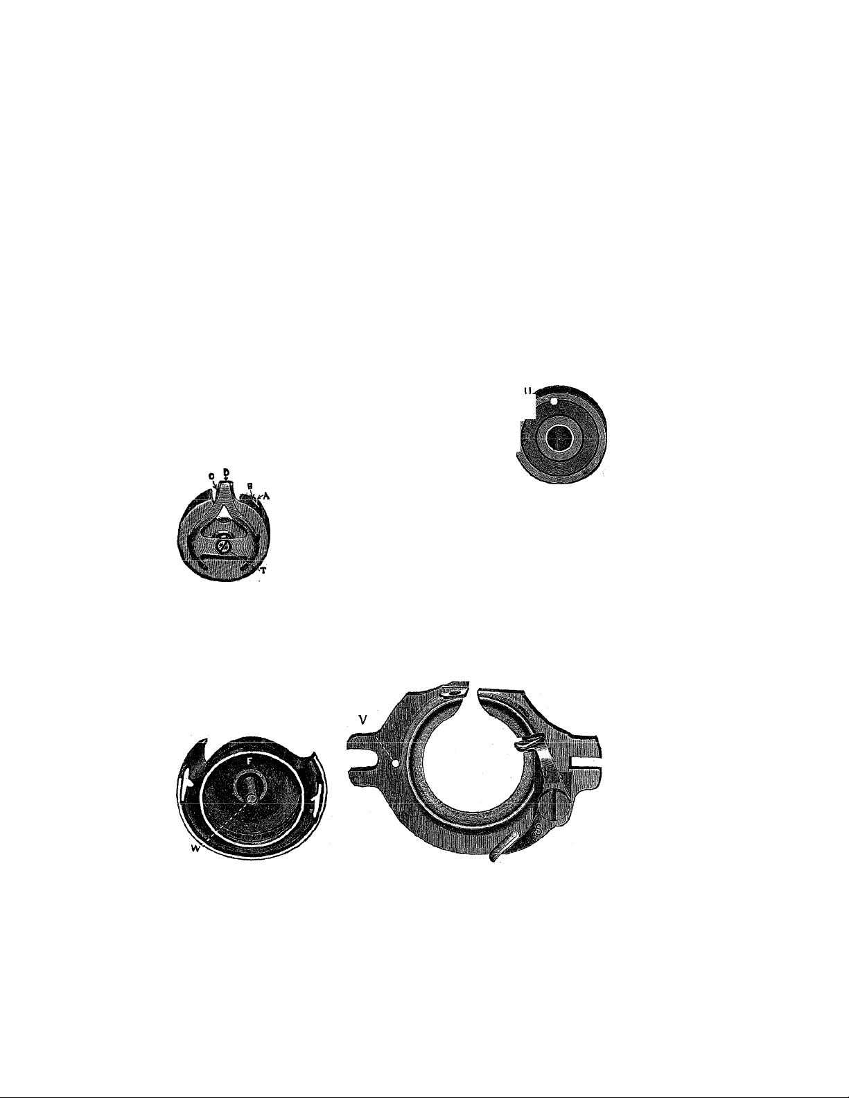
LOWER TENSION
Pig. 8 represents the bobbin case. To regu
Fig. S, Bobbin Case
late the lower tension, turn the screw T to the
right to tighten, and to the left to loosen the same.
TO THREAD BOBBIN CASE TENSION
Place bobbin in case so that thread will come from bobbin on
same side as hole B in bobbin case; pass thread through slot A to
hole B thence across opening, drawing it down under lip C then
pull it up until thread passes out under tension spring D.
The tension on bob
bin case should be the
same as the upper ten
sion.
Fig. 9, Shuttle
Fig, 10, SHrattle H»«e Cove»
Page 6
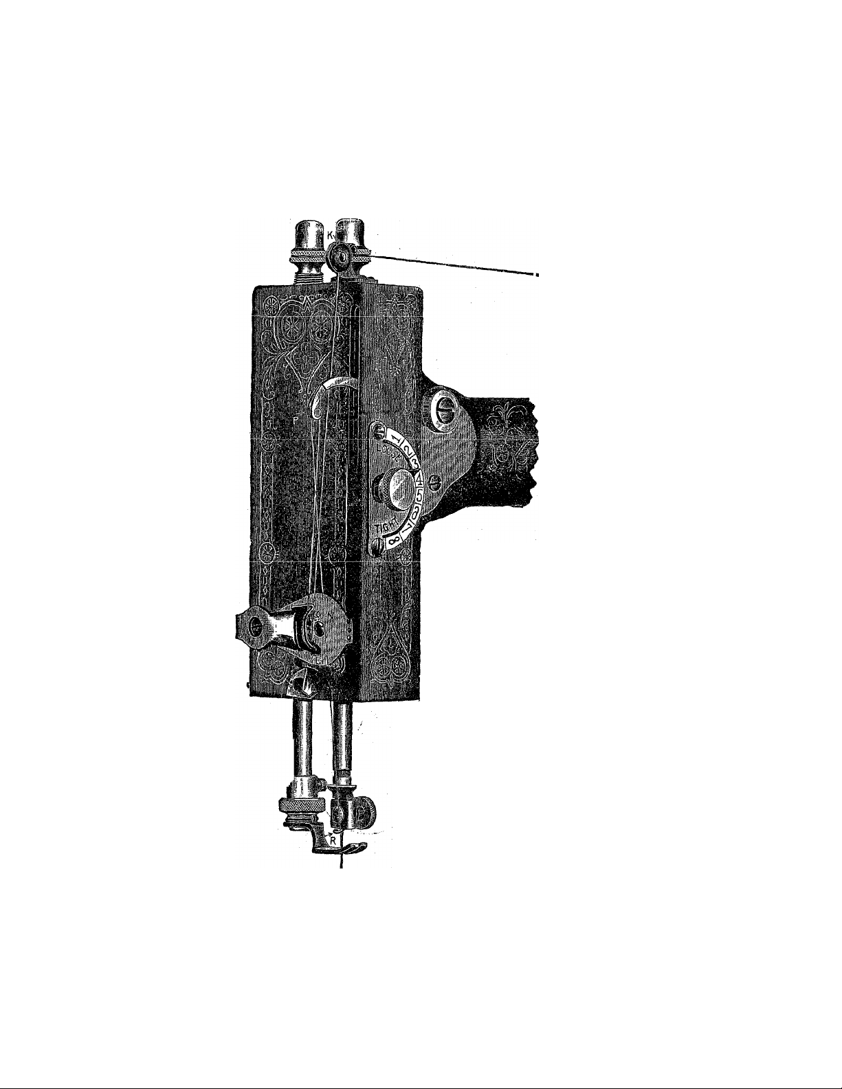
i>lMctiONS FOR THREAbiNd
Place the spool on spool pin, take the thread in your left hand
holding it taut with the right during the whole threading operation.
Pass thread from
spool over check
spring K at top of
face and down
under point L
now pull thread
upward until it
passes through
the eye of spring
N and into notch
O, then into end
of .take-up pthen
down through slot
R in end of needle
UCli ctliU
eye of needle from
left to right, al
lowing about 3
inches of thread
when take-up is at
its highest point.
To draw up the lotver thread, r&ise
the presser-foot, take hold of end of
upperthread and turn, the handw;heel
once around, (moving upper side of
wheel from you,) which will drawthe
lower thread up through needle hole.
Pass the ends of both threads
under the presser-foot and you will
be ready to sew.
Note.~T}o not run the machine with
the presser-foot down on the feed without
cloth under it. Do not pull cloth cc or from
you in such a manner as to bend the needle.
THE TENSION
The illustration above represents the Ten
sion Regulator and Indicator for the upper
thread, an entirely new and useful device:
The half circle is marked with a scale run
ning from 1 to 8, with the word “loose'’ at
Ä
_____
-t
____
Jf TWT-.
Ki- 12
ngUre X auu ugiit at inu. 8, No. 1 being
the slack and No. S the tightest tensior
Page 7
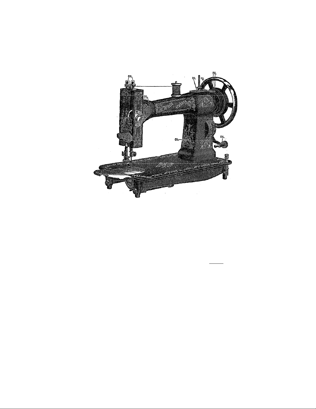
OIL PLACES AS INDICATED BELOW
The regulator is located at the right end of machine on the front side or
•arm. TO SHORTEN stitch more the lewr down. TO LENGTHEN stitch
move lever up. No. 1 indicates the shortest, and No. 7 the longest stitch.
TO CHANGE THE LENGTH OF STITCH
TO REGULATE THE TENSION
To loosen the tension, turn the thumbscrewon the dial to the left
n-xrVn tTr4 11 -Art»TTi«zi
VV .iI.J.V/i.1. VV iXA AAIV,# V ^ L/AA\P JjJV/AAA UW¥ CU.X VAO AAg VAA W 1.
4'n■?4' 4*nT»v» 4-/%
A. \J V/A^AAWC^AX Ml/f VUXAA \j\J
the right, moving the pointer towards No. 8. By this means the
;same tension can always be duplicated, thus obviating the necessity
•of experimental trials, as is the case with other machines. If a tight
tension is desired, both upper and under threads must necessarily be
tight. If the upper thread is tight and the lower thread loose, the
upper thread will be drawn to the top thus: If the
lower thread is too tight, it will be drawn straight on the bottom of
goods, thus: \ When you desire the goods to look alike
nn both sides, and be elastic, balance the tension thus:
THE TENSION RELEASER
, The tension releaser is operated by the presser-bar lifter. By
means of it, all tension is taken off the upper thread when the
presser-f oot is raised, and the work can be taken out without pulling
the thread down by band.
^PARTICULAR NOTICE—The tension cannot he regulated when the lifter
is up because the Releaser is operated by the presser-bar lif ter,
7
Page 8

TO COMMENCE WORK
In tiireRdin" the needle mid bobbin case rt.speclively.yt'U .shoidd
leave an end of thread about two inches in lenjfth to cacli. ilold the
end of the upper thread loosely in the left hand, and with tlie right
hand pontlyrevolve the hand-wheel until the needle passes to its low
est point and rcUinis. a loop will be foniK.-d through wijich the shut
tle will pass, and. as the needle ascends it will draw up the Icrvor or
shiittlc thread, and the machine is ready for praclicrd operation.
TO REMOVE WORK
Step the machine with the take-up at its liighesl point J riUjsG the
prts.sci’-foot with the lifter which slackens the upper liiread; then
lake hold ofynur work with your left hand and pul! it direct'.y from
you, keeping the top thread in the slot of the presser-foot, '.vhici'. wiÜ
prevent bending ihe needle. Now raise the work and draw the
threads into the tliread cutter on the pressor-bar and indl dovnward, which wil! cut the ilireafis iiie proper length to com.Tiente
wi>rk again.
EXPLANATION OF DIFFICULTIES THAT SOMETIMES
OCCUR WITH BEGINNERS
If the t'jip^r Hrrio.f.l brrul:-'-'. it may be caused by the needle not
is.ing properly .sot. or the itn-.cldne no: tht-'-aded correct iy, or the
u]iper ten.-ioa loo tight, or the thread une'on and the nocdl... p,.-;
.small J'i>r it, or the needle eye to.,» .sharp, or the presser-i'ool attached
to the machine so that the needle rubs it iti pa.-sing.
If liu ni'-<h i‘ iln rm! hi i'i!:.'!. it may be ca.useii by the bo'oi.'in ca;.c
i.'cing improperly Ihreaded. or too much Un.sion upon it, or by the
bobbin being wound loo full .so that the thre.-id slips ovf-r the ends of
the bor>bin in the oe'hbi.n case.
If flic nx.dfc breahK. it is more than likely your oun fault,
cau.sed by pulling the goods to or from you in .such a rnanner Und
the needle .«irijces the Ihro.at plate atul is botuid to break. Tin? nf.-odle
nu'-y however, break in trying to sew cxlra.ovdin.avy heavy sejun.-;
when the pressure on Ihr- presser-foot is no: lieavy enough.
To create more pressure upon the goods turn the pro.ss.or-bar
nut on top of the prosser-bar to the risriit : to derr-cise ihe pre-sore
Tarn it to the left.
If it makes loop stiUrhe.s, it is most sure to be cau.sed 'ny t ]oc-.,o
!( nsion both top and bottom.
If ihf y!:ipf> .'■f-ichcs.ih^ ri'.edie i - either btu:! cr me in
right position.
I f the sHli.lii’s lire i”if (. I I /?, it may h-.- caused by the pres-or-''c't
not resting evenly upon the fabric sewed, or b'e the feed n')l being
nigli enou.gli. or by the stitch being too sh u-t. or l;y pulling tlie clo^h
(■■r by using too fine? a nedlie with too coarse or urseven thi’oad.
Tf i.he machine should be run without .sewing and thread get in
!lic shuttle race making' the ■/><:■ rnn heui'ii. lake out bobbin cas-.-
.'ind runtho machine in Ihewj’ong directio:, ;itwill cut the thrciid oub
-Vij.'iVf- Tl-n ic-ii'iu!!' liaivl i'houid idwav-' \ e ti:;'?!'. eaouvr’ii ns; to slie. if ¡',
'Pj’S or does Tie* fo;'ce ti:e m-(-d!e ti'-rouch thick gonds, cut oif a vi '-v shorr n!,;cc
and re ailju.-r t’nr ends. The belt should rot Vo so ticht a; to p'-rvont au (.‘■.vS;’
niotifn o' liic onichiac.
C:
i-
Page 9

ulKtuiUJiN::» tuK u;3j;nu injc. a 11 ACnm£.iN i :>
*
^ ■ -..■■■ ■ --. = ---
?S==S~^^====B=
' -
Hemming
Raise the lakc-up to iis liigliest poini. remove the presser-fuot and
in its place attach the hcnimcr. Trim the cdj,‘e of doth on a curve
and insert in hcimner far criougii to permit the needle to enter the
cloth at its extreme edije, (See Fiy. 2 above), then proceed to sew.
keeping the edge turned as it feeds through.
Felling
Tiic hommer is also the feller. Sc'.v together two piece.s of clotlt
with tlio under edge projecting be-iwecn .'.■ and '■ ! inch beyond the
tipper edge; then trim the edges if necessary and opcii the work; oat
\^roiig -ide up. and fold down the wider edge, toward the left, over
tl'ic narrow edge, and then pass the ¡folded edge info the feller the
same as in orrlinary hemming.
lihistration above represents an oj»erator in the act of compietuig
Page 10

lie s
Zs:
Page 11

No.
14® Take up roller stHd
141 Take up roller ...
Take up screw lor хз
2T9
263 Screw to fasten stitch Indicator
264 Screw to fasten attachment holder
266 Screw to fasten rear feed rock arm
267 Screw for head of main connection
268 Screw to bind screw 760 in shuttle
210 Screw to fasten face
215 Screw to fasten -presser bar lifter
233 Qullter .............................................................
234 Screw to fasten qullter and thread
345 Gauge screw
271 Presser bar lifter washer
276 Screw to fasten S33 to face
279 Needle bar bushing
280 Needle screw and clamp ........................
281 Needle screw nut
341 Washer for 72S ...............................................
342 Attachment holder complete............................
343 Presser foot
345 Hemmer
347 Presser bar lifter and releaser cam.
348 Presser bar lifter screw
355 Tension indicator -complete
357 Tension disc ......................................................
359 Screw and nut to connect 35S and
360 Guide pin In slot of tension plate.785
363 Screw to adjust lower end of face..
364 Screw to clamp feed bar centers 726
see Thread cutter
369 Needle bar .........................................................
452 Head latch guide washer
153 Head latch spring
154 Head latch nut .................................................
536 Lock nut for 758 ..............................................
540 Screw to fasten 767 in arm
542 Head latch .......................................................
543 Washer for head latch sprmg...........................
548 Foot gatherer
593 Stud for revolving spool standard ..
594 Sleeve for revolving spool standard.
595 Screw to fasten 593 in arm..............................
617 Bobbin winder pulley
701 Screw to bind needle bar link screw
702 Screw to fasten feed cam 763, and to
704 Screw to fasten main connection stud
705 Center for feed rock shaft 72i and
706 Nuts for 705 and 797 ......................................
707 Screw to connect 714 with 723 and
708 Nut for 707 and 721 .,i...........
710 Pin in feed fork for shifting block
711 Shifting block In feed connection 714
714 Peed connection
715 Peed connection link
716 Pin for feed connection link 719 . ■ . ■
717 Stitch adjusting lever.......................................
718 Stitch adjusting stud ^
719 Friction washer for 717
720 Sleeve for 71S
.............................................................
plate 722 take up plate 798, check
spring bracket 794 ......................................
342 to presser bar 775
723 to rock shaft 724 and thread
pull o£E rock arm 755 to rock shaft
758 ..............................................................
747 ...................
race .............................................................
block 779 and guide 780 to presser
bar 775 ........................................................
cutter ...........................................................
.....................................................
.....................................................
............................................................
858 Tension spring on inside of face ...
7S5 ..............................................................
In feed rock shaft 724
.....................................................
...............................................
784 In take up cam 762
locate take up cam 762
708 Screw to tighten take up cam 762 on
shaft 761 and to fasten 842 in arm
751 In
....
thread pull off rock shaft 756 .. .
754 W'ith 756 and to fasten bobbin
winder to arm .............................................
711 ......................................................... ■ ■
................................................
ed! e 'jar bushing
................................
......................................
............
.............................
....................................
...............................
.........................................
............................................
...................................
.............................
.............
...................................
............................................
...............................
.......................................
...............................
...............................
................................................
.........
....................................
...........
...........................
.....................................
...................................
....
...............
..
■
No. Price
Price
721 Screw to connect 715 to 717........................... 06
$0 05
722 Stitch Indicator .plate
10
723 Eock arm on rear end of feed rock
02
02
02
02
03
02
03
02
10
02
05
f)l
02
06
10
05
01
40
25
40
15
02
50
03
05
06
01
02
02
02
25
02
ПЯ
05
02
02
05
02
S.j
05
05
02
08
02
02
02
02
06
03
06
02
03
07
26
13
05
12
15
02
03
shaft 72» .................................................... 13
724 Feed rock shaft................................................ 50
725 Feed bar .......................................................... 50
726 Centers for feed bar 725
727 Feed
728 Screw to fasten feed 727 to feed bar
729 Spring washer tor bobbin winder
730 Shuttle race
731 Latch to hold shuttle race cover 834
732 Spring for 731
733 Pin for 731....................................................... 01
7S4 Spring pin to hold shuttle race cover
735 Spring for 734 ................................................ 02
736 Washer on 734
738 Thread guide plate on S34
739 Screw to fasten 738 to 834
744 Bobbins
746 Crank on rear end of shuttle shaft
747 Main connection complete
745 Main connection roil
749 Screw to adjust main eoimectlon to
750 Main connection slide block
731 Main connection stud ....................................... 15.
752 Feed raising and thread -pull off cam 20
753 Screw to fasten 752 to 80S
754 Eccentric connection for thread null
755 Thread -pull off rock arm
736 Thread puli off rock shaft.................................. 25
757 Thread pull off ................................................ 59
758 Screw to connect 757 to 755 .......................... Ó2
750 Thread pull off slide block
760 Screw to connect 759 to shuttle race
761 Upper shaft
702 Take up cam ..................................................... 50
763 Feed cam.......................................................... 25
764 Screwtogoinrearendof 7éí
765 Forward hushing for upper shaft 761 25
768 Screw to fa-sten 765 in arm S14 and
767 Rear bushing for upper shaft 761.. 20
770 Needle Plate
771 Screw to fasten 770
772 Bobbin winder complete
775 Presser bar ;..................................................... 15
776 Presser screw .................................................. 15-
777 Needle bar cap ................................................ 15
7TS Presser bar svjring
779 Presser bar lifter block
780 Presser bar guide
781 Needle bar link
782 Needle bar block ............................................. 15
784 Screw to connect T81 to take up cam
785 Tension plate
788 Auxiliary spring ................................................ 12
787 Adjusting washer for 786
759 Screw to connect 8.39 to S3i and
790 Take up complete
701 Take up screw.................................................... lo
792 Spring for latch 839
793 Take up cover plate
794 Check spring bracket ...................................... io-
793 Rear spool standard
796 Rear cover plate ................................................ 08
797 Table hinge compiete ..........................
799 Washer for 797
...............................................................
725
........................................................
frame .......................................................... 01
on race 730
834 on race 730
..........................................................
80S ............................................................. 25
slide block 750
off
..............................................................
730 ............................................................. 03
782 to 309
762 06
to Inside of face 813
(Continued on next .page.)
..........
........................... 10
.................................
....................................................
................................................
................................................
.........................................
......................
....................................... . 02
.....................................................
..................................................
...................................................
...........................................
............................................
........................
...................................................
.............................................
..........................................
.......................................... 02
...........
.............................
............................
.............................
......................................
...........................
.............................
...............................
...............................
................................
........................................
................................
...................................
..................................
...................................
.......................................
........................................
11
.............
......................
...........
05 ,
b‘0
02
1 25
08
02
05
01
07
02
S8
75
10
15
02
15
15
10
1 50
¡0
02
40
02
33
19
25
15
25
So
02
02
40
02
0.5
08
SO'
Page 12

No.
802
Strew to locate needle bar block 782 02
SOi
807
80S
^809
Í813
*814
815
820
821
822
823
824
82G
827
S2S
829
S.30
831
832
833
834
835
836
837
838
Screw to clamp shuttle race 730 anti
shaft 808 ......................................................... 02
Gauge ...................:.......................................... 05
Shuttle shaft driver and thread cast
off complete................................................... 1 00
Screw to adjust auxiliary spring 7S6 02
Bed
Arm .................................................................... 2 73
Pace .................................................................. 1 23
Screw to fasten tension Indicator
355 to 813.......................................................... 02
Washer on auxiliary spring 786.... 01
Washer under latch S39 ........................................ 01
Stud for lower end of main connec-
aon 747 ............................................................. 03
fetén S42 in arm................................................. 03
Plate for 725
Sirort rivet for S26
Long rivet for 826
Screw to fasten hed to arm .............................. 02
Hand hole cover complete
Lfltoh for cover 830
Spring for latch 831
Catch on lower end of face to retain
cover 830 when raised
Shuttle race cover .............................................. 1 00
Shuttlé
Bobbin case complete ........................................... 60
Bobbin case tension spring ........ 07
Bobbin case tension screw' ................................... 02
to take up rear bearing of shuttle
....................................................................
Screw to fasten crank 746 on rear
end of shuttle shaft SOS and to
........................................................
................................................
................................................
............................
..............................................
...........
................................... 03
.....................................
..............................................................
Numbers preceded by a star (*) are not illustrated
Price
2 75
02
05
02
1 00
20
03
1 50
No.
So9
Latch to retain bobbin ease 836.... 10
840
Auxiliary cam
Feed fork and stud complete
841
Bearing for feed fork stud
842
Screw in end of feed fork stud .... 05
843
*84, .5
Loose pulley on hand wheel
846
Wire retainer for 845
847
ffhumb screw in hand wheel.
848
Ijock washer for 847
852
Screw to fasten hand wheel toupper shaft 04
*8 5 3
Hand wheel
855
Bobbin winder center
..................................................
......
................................................
............................
................................
............................
.......................................
...........................
......
..................................
......................................
Price
' 05
3.5
15
SO
- 06
OS
02
2 00
OT
DIRECTIONS FOR USING THE FOOT GATHERER
Remove the presser-foot and replace with the Gathering Foot
TO GATHER, PUFF OR SHIRR
Place the goods under the foot the same as in ordinary sewing.
For fine gather use a short stitch. To increase the fullness lengthen
the stitch. For greater fullness tighten tension.
12
Page 13

HEMMING AND SEWING ON LACE
ONE OPERATION
Our hemmer and feller which accompanies each machine, is
now made with a slot—6. (See illustration above.) In this sloB
place the edge of the lace and sew it on at the same time as In
ordinary hemming.
WIDE HEMMING
Any width hem can be made with the hemmer and feller upo»
thin fabrics by simply folding the goods the desired width of hem
and then passing the edge through as in narrow hemming,
13
Page 14

Cl«.* •
Draw out slide of machine
about half way, insert ear of
shirring plate into gauge screw
hole in needle plate, and holding
down the shirring slide, push
slide up in its place, and fee
shirring slide will be held firmly
in that position.
Loosen screw 6 (see page 16)
and remove separator, placing
the goods to be shirred between
the blades, and shirr at any de
sired distance. ^
Be careful not to use rufiier without separator or shirring blade
and cloth above,
for in so doing the rufiier teeth will be broken or
injured.
To Put Ruffling on a Band Edge Stitched With
or Without Piping.
Take striped calico or plain colored goods, cut on the bias in
strips full one half inch wide, folding in center. Place the piping
in guide 7 with folded edge to the right, then take the band and turn
down on edge a quarter of an inch and place in guide 8 having both
ends down under foot. The guide can be adjusted to right or left by
loosening screw 9. Place the ruffling to the right between the blades
and in guide 4; if wider ruffling is desired remove separator and us€
shirring slide. To use facing with shirring slide place facing unde:
shirring blade 1 and in guides 2 and 4.
To Make Heavy Pleating.
Cut Lonsdale cambric in strips one inch wide lengthwise of the
goods, fold in the center and press the folded edge down smooth.
Adjust the goods with folded edge to the left and between the
springs of>ruffler, then in gauge 4 (see page 16). Set a long stitch,
turn adjusting nut 5 to No. 4 on gauge, placing the band in guide 8
in the same manner as when using piping. This will make a very
large sized pleat and be stitched on the band.
To Make Scallop Ruffling.
Place the goods in rufiier just the same as for making large'
pleats, except to remove guage 4 from rufiier and shorten the stitch
of machine. While sewing, move the goods to the right and lef^
alternately and far enough to make the scallops of desired depth
Scallops can be made of uniform length by counting the same num. '
ber of stitches between each alternate movement to the right or left.
17
Page 15

OIL PLACES INDICATED BELOW
KEEP MACHINE WELL OILED
Oil in the all the places indicated on page 7. To oil the under
side of machine, slip the belt off the balance wheel and turn the
machine back on its hinges and oil in places indicated above.
THE IRON STAND
Oil occasionally the treadle centers, upper and lower end of pit
man and the balance wheeThub bearings. Whenever you oil the
machine work it a little to distribute the oil. After standing a few
moments take a soft cloth and clean the superfluous oil from the
Japaned parts of machine.
TO CLEAN MACHINE
If the machine is dirty or gummed up with poor oil, oil thorough
ly in places indicated above and on page 7, using Kerosene (coal oil)
run the machine for a short time, wipe dry and oil with good sewing
machine oil.
18
Page 16

Hemming
We furnish with each machine five
assorted widths of hemmers. Select
the width desired and substitute it for
the presser-foot. Take the cloth in
both hands, the right hand in front
of the hemmer and the left behind.
Place the edge of the cloth in the hemmer drawing it back and forth until the hem is formed, stopping with
the end under the needle. Drop presser-foot and commence to sew
Guide the cloth so as to keep the hemmer full. To change stitching
near or far from edge, loosen thumb screw and move hemmer to
right or left as desired and tighten screw.
Binding
Remove the presser-foot and sub
stitute the binder. Cut the binding yi
inch wide (on the bias if convenient).
Pass the binding through the scrolls
\ of the binder and under the presser-
■ r
cloth with the left hand, and let the binding glide easily through
the fingers of the right. To change the stitching near or far from the
edge, move binder lug A to right or left as desired.
foot. Place the edge of the goods to
be bound between the scrolls of the
binder, drop presser-foot, guide the
Under-Braider
Substitute the under-braider foot
(which is found in the box of attach
ments) for the regular presser-foot.
Place under - braider on machine
same as the shirring plate; draw the
braid under and through the tube
and a httle past the needle. The
pattern to be braided should be
stamped on the wrong side of the cloth. Place the goods under the
presser-foot same as in regular sewing, following pattern carefully.
This stitches the braid on the cloth from the underside.
19
Page 17

Stand for Nos. 74, 75, 76, and 85
T 623
2Q
Page 18

Parts for White Sewing Machines may be
Secured Anywhere
list of stand Parts for Ball Bearing Stan&,White Box Top, White Automatic Swing J>ropa
Nos. 70. 74. 75, 76, 77. 80 and So and CabiiketaNos. 72,and 78
206
207
209
211
223
Stand caster ......................................................
Pin in stand caster
224
225
Stud in treadle, for pitman.
231
309
Pelt head tack ........................................
364
379
*384
Brace for box top
*385
Dress ^ard for box top
Rest pin in table for box top.................................
*389
437
Pin in head carrier for slotted stop
513
Screw to connect cable to lid
516
Screw to connect cable to lever
517
Nut for adjusting stud...........................................
519
Drip pan for Nos. 70, 74, 75, 76, 77,
*530
Spring for swing bottom
531
532
Eyelet for 531 — . ...............................................
Drip pan for Nos. 72 and 78
*533
Latch plate for head carrier........................
544
Treadle for No. 80 drop........................................
*550
Treadle support for No. 80 drop
*552
553
Caster for No. SO drop
563
Screw to fasten treadle support to leg...
564
Treadle for Nos. 72, 74, 75, 76, 77, 78,
565
566
Treadle center ......................................................
567
568
Dress guard for Nos. 70, 72, 74, 75, 76,
569
Screw to fasten link No. 621 to plate
No. 630 ............................................................
Adjusting screw in lower end of pitman
Screw to fasten stud in treadle, treadle
pin in balance wheel
centers in treadle support and crank
Screw to fasten dress guard and brace to
leg
...................................................
Wood screw to fasten swing drawer to
table .................................................................
Set screw to tighten balance wheel cone
573 and crank pin cone 577
Balls for balance wheel and pitman, per
100 ................................................
Brace for Nos. 74, 75. 76 and 85 drops..
80 and 85
Treadle support for Nos. 74, 75, 76 and
85
...
.................................................................
and 85
Pitman for Nos. 70, 74, 75, 76, 80 and
85 drops
..........................................................
Balance wheel for Nos. 70, 72, 74, 75, 76,
77, 78. 80 and 85
77, 78, SO and 85
.......................................
................
...............................................
..................................
........
..................
.........................................
......................................................
......................................
................................
........................................
.......................................................
...................................
..........................................
..............
....................
...............................
...........................
..........................
..
..................
.......................
..
..
..
Numbers preceded by a star (*) are not illustrated.
Where the parts such as pitman, treadle rod, etc. are ordered to be sent by mail,
postage will be charged thereon, '
570 Stud in dress guard for balance wheel
.02
.03
.02
.02
.05
.02
.02
.06
.02
.02
.50
.60
.50
.05
.60
.01
.02
.02
.02
.25
.06
,01
.25
.04
.75
.50
.10
.50
.03
.50
1.50
1.00
.10
.06
568
571 Nut to fasten stud 570
572 Rear cone for balance wheel stud 570... .05
573 Front cone for balance wheel stud 570.. .08
574 Ball race in balance wheel hub
575 Bail retainer for ball race 574.
576 Crank pin in balance wheel, for pitman
577 Front cone for crank pin 576
578 Ball cage for crank pin balls, with balls .08
^579 Pitman for No. 77.................................................... 50
*580 Treadle suppoii; for No, 77..
*581 Right leg for No, 77
*582 Left leg for No. 77
*583 Pitman for box top......................................................50
*584 Treadle support for box top........................................50
*585 Right leg for box top
*oS6 Left leg for box top
*587 Balance wheel for box top.................................... 1.50
*588 Stud in leg for balance wheel 587...... ,15
*589 Treadle support for Nos. 72, 78 and
#590 Pitman for Nos. 72,. 78 and cabinets. .50
*592 Treadle for box top.....................................................75
599 Wire bail for belt grip................................................08
600 Clip for 599 ........................................................... .02
601 Spring for 599........................................................ .05
*603 Treadle for No. 70................................................... .60
*604 Treadle supnort for No. 70
*605 Brace for No. 70........................................................ 60
619 Cable adjusting lever
620 Adjusting stud and plate for cable lever. .15
621 Link to connect swing fi'ont to head
622 Cable (20 in. long) for Nos‘ 70, 72, 74,
623 Cable guide ..............................................................30
624 Swing cover for corner of head carrier.. ,30
625 Eight kg for Nos. 70, 74, 75, 76 and 85. 1.75
626 Left leg for Nos. 70, 74, 75, 76 and 85.. 1.75
#627 Brace for No. 77.,
630 support for cable adjr^ting lever No. 619 .10
631 Head carrier hinge ....................................................06
632 Pin for head carrier hinge No. 631...,. .02
.....................................................................
(including rear cone) .......................................
cabinets * • 50
carrier ............................................................... .29
75, 76, 77, 78, 80 and 85...........................20
.........
......................................
.................................
..................................
......................................
......................................
...............................................
.................................................
..............................................
.................................................
.......................................
................................................
....................................................
15
.12
1,75
1.75
1.75
1.75
60
08
02
50
60.
03
08
20
f{0
21
Page 19

TUST one more tíme saver which the busy user wili eagerly
welcome—a Scissors Gauge with which one can easily and accu
rately cut bands of various widths, either straight or on the bias.
It’s an attachment, the value of which will be grasped on sight
by every sewer and highly appreciated for its thorough utility.
This attachment is included free with the attachments supplied
with this machine.
THE SCISSORS GAUGE
The Scissors gauge is for cutting bands qf various widths, either
itraight or bias. The sliding scale is adjustable for the widths of
band desired.
Place the gauge upon the scissors, as shown in the illustration,
slip the edge of the cloth in the gauge and proceed to cut the band.
The tape for the Binder should always be cut on the bias, also th©
piping which is used with the Ruffler.
The letter P indicates the proper width for
a bias fold, which is to be one-half of an inch
wide when finished.
The Scissors Gauge »fhe letter B indicates the width for cutting
bias bands which are used with the binder.
C is for corded or plain piping. The piping is cut bias and
. folded double to use with the ruffler.
With the aid of this gauge any
number of folds may be cut of
exactly the same width. Those
who have tried know the difficulty
of doing this with the scissors
alone. Everyone who uses a bias
gauge is delighted with it.
O
rlaoing the Gauge Ou the Scissors
Buy a yard of 44 inch lawn.
Cut it into bias strips % to 15-16
of an inch wide. Roll it on card
board and keep it in the machine
drawer. It will furnish the bind
ing for the inside seams of the
>£white se wing for months to come.
22
ti
©
Cutting a Bias Band with the help of the Gaug«
Page 20

THE EDGE-STITCHER
A Combined Edge-Sdtching, Lace-Joining and Piping Attachment
HE EDGE-STITCHING ATTACHMENT is fastened to the
machine in the same manner as the Presser-Foot. The
T
different slots which are numbered from 1 to 5 in the illus
tration serve as guides for sewing together laces, insertions, em
broideries, sewing in position folded or hemmed edges, bias-folded
'•tai*
material or piping, etc.
This Attachment is very useful in trimming such articles
of clothing as aprons, women’s and children’s dresses and under
wear, shirtwaists, silk blouses, boys' rompers and suits, or for articles for household
decoration such as fine bureau scarfs and thin curtains, baby carriage covers and
doillies.
Very beautiful effects may be
obtained in yokes, guimpes, sleeves
collar and cuff sets, vestees, fich
us, lace waists, camisoles, etc. by
joining rows of lace insertion alter
nate rows of lace and embroidery
insertions, or alternate rows of
tucking and lace insertions.
The folded tape, whidh may be
purchased in any department store
in all colors, qualities and widths
is indispensable to use with this
Attachment. The folded piping,
which may also be purchased
ready turned, will exactly fit the
piping slot in this Attachment.
How to Adjust the Edge-Stitcher
To adjust, move the lug A (see illustration) at the left of the attachment to
the right or left until the desired adjustment is obtained. When sewing two pieces
of lace together, it is very necessary that the attachment is adjusted to stitch ex
actly on the edge, so that the edges will not fold over when laundered.
When sewing laces or soft materials together, it is better to hold the edges
slightly overlapped. This will prevent the lace from feeding away from guide.
When the attachment is properly adjusted, the most inexperienced operator
may sew yards of lace or material together with no difficulty. '
Practical Uses of the Edge-Stitcher
1. Sewing lace and insertion together.
2. Sewing lace and embroidery insertions together.
3. Piping plaits and belts for children’s clothes.
4. Sewing tape to top of stocking to prevent "runners” (patented). -
5. Sewing insertion on material—afterward cutting material away and turning
edges back.
6. Sewing lace on edge of hem.
7. Setting in insertion with edges edge-stitched.
8. Sewing lace and ribbon together.
9. Covering seams with bias bands or finishing braids.
10. Sewing braid on heavy suits and dresses.
11. Sewing on bias bands for trimming—straight or curved. ,
13. French seaming.
23 , V
ipia
Page 21

Practical Buttonholes made with the Binder and Hemmer
It is the desire of every -women to understand the art of rnaking fine buttonholes,
but many women do not have the time to spend working them, even though they
are skilled in the art.
Good practical buttonholes can be made on the sewing machine with the help
of the Binder and Hemmer. These buttonholes are strong and durable and will
wear as long as the garment. They are neat and good looking and a dozen can be
made in a fraction of the time it takes to make one by hand. These buttonholes
are especially practical for children’s underclothes, rompers, dressses and for the
backs of Princess slips.
Directions for Making
If the buttonholes are to be two inches apart, take a strip of material two inches
wide and bind it as shown in B. The marks show this strip divided into sections.
Each section is one-half inch wider than the button. If your button is one-half inch
across add one-half inch, thus cutting your strip into pieces 1 inch wide. If the
button is three-quarters of an inch wide, add one-half inch and cut strip into sec
tions one and one-quarter inches wide.
1
C
A ft^r ■yriur !e+riT\
the presser-foot. Bind the edges with bias binding as shown in D. This makes a
finished strip of buttonholes which are strong and practical for children’s clothes.
E shows the same idea worked out with finer materials; the Foot Hemmer in
stead of the Binder is used to finish the first strip, in order to get an effect dainty
enough to use with dimity, batiste, etc.
E also shows the edges sewn to another piece of cloth, which in Hte case of
practical sewing would be the garment. This is done when they are in the stage as
shown in C, binding the edge of the garment in with the row of buttonholes, then
stitching the free edge of the binding flat on the garment, using the presser foot.
rse eoTir i ■i-a
k.'V'V/ka
iC.i: bv/gCvxxvyS wxxw tt a.4 ix*. v^>
26
j
Page 22

■
■,;.V-i- .■< '. -.--■i.-'- '--.V'V '.■ ;..
WHITE SEWING MACHINE FACTORY, CLEVELAND. O., U. S. A.
■
 Loading...