

Page 1
HOW TO USE AND CARE FOR YOUR
ZIG ZAG
MODEL K-lOO
SEWING MACHINE
IMC^TRlirTION RnniC
Page 2

CO NTENTS
1.
MACHINE AND FEATURES
2.
BELT ADJUSTMENT ..
3.
REPLACING NEEDLE ..
4.
REMOVING BOBBIN CASE
5.
WINDING BOBBIN
6.
ADJUSTING BOBBIN WINDER
7.
THREADING BOBBIN CASE
8.
REPLACING BOBBIN CASE
9.
THREADING MACHINE
10.
PREPARING TO SEW
11.
ADJUSTING UPPER THREAD TENSION
12.
ADJUSTING BOBBIN THREAD TENSION
13.
ADJUSTING FABRIC FEEDERS
14.
ADJUSTING PRESSURE OF THE PRESSER FOOT
15.
regulating STITCH LENGTH
16.
ZIG ZAG SEWING
. (Front)
(Back)
..........
............
Regulating Width of Stitch .......................................
Locking Zig Zag Regulating Lever
17.
STRETCH STITCHING
18.
CLEANING SHUTTLE AND RACE ASSEMBLY
19.
OILING THE MACHINE ......................................
20.
BUILT IN LIGHT ..................................
21.
ACCESSORIES ..............................................................................
A. Presser Foot for Straight Sewing
Making Patterns
B. Cloth Guide
C. Zipper Foot
.........................
..............................
D. Buttonhole Foot
22.
BLIND HEMMING
23.
APPLIQUEING .................................................
24.
EMBROIDERING AND MONOGRAMMING
25.
DARNING ...............................................
26.
SEWING ON BUTTONS
27.
CAUSES OF COMMON DIFFICULTIES
..............................’.........
............................
.............................
................................
..........................................
........................
................................
' .
.......................
........................................
........
J3
'
.......................
" 19
.....................
.............
.....................
....................
....................
.....................
.......................
.......................
Page
1
2
3
3
3
4
5
5
6
6
7
9
9
10
11
12
& 14
15
16
17
17
18
19
20
21
21
22
22
23
24
Page 3
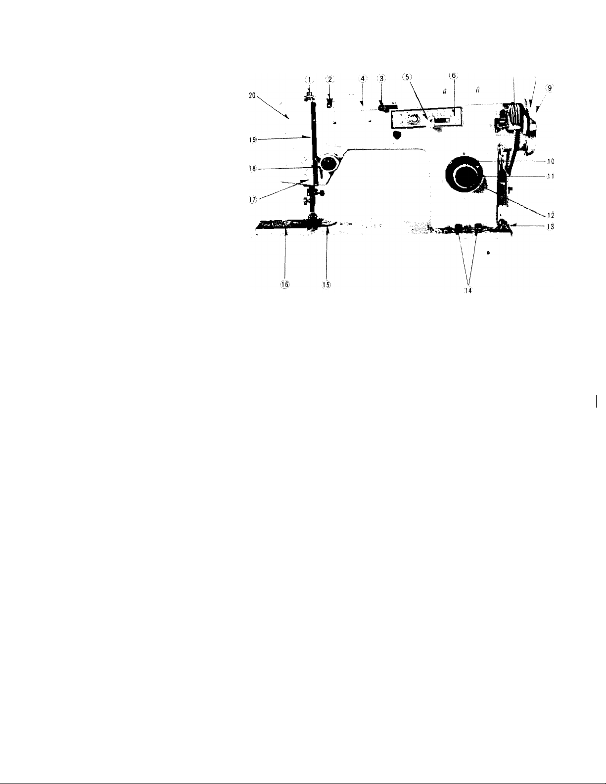
1 . MACHINE AND FEATURES
Fig. 1
.7 ;8
FRONT
1. Pressure release (darning)
Thread guide for top cover
2.
3. Stretch stitch control
4. Top cover
5.
Zig zag width control
6.
Zigzag indicator
7. Bobbin winder
Fly wheel
8.
Clutch nut
9.
10. Stitch length indicator
11.
Stitch length control dial
Reverse button
12.
13.
Bobbin winder .tension
14.
Drop feed buttons
15. Needle plate r
16. Cover plate (Slide plate)
17.
Thread guide
18. Tension
19. Take up
20. Face plate
4‘
1
1
1
Page 4
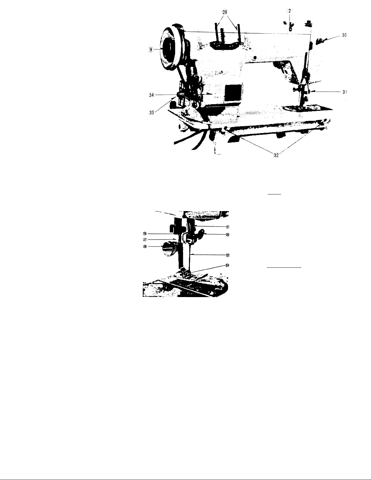
Fig. 2
Fig. 3
Fig. 2
21. Needle bar
22. Needle clamp
23. Needle
24. Presser foot
25. Fabric feeders
26. Presser foot clamp screw
27. Presser bar
28. Thread cutter
BACK (Fig. 3)
29. Spool pins
30. Light switch
31. Presser bar lifter
32. Head hinge mounting holes
33. Motor set screw
34. Motor
Page 5
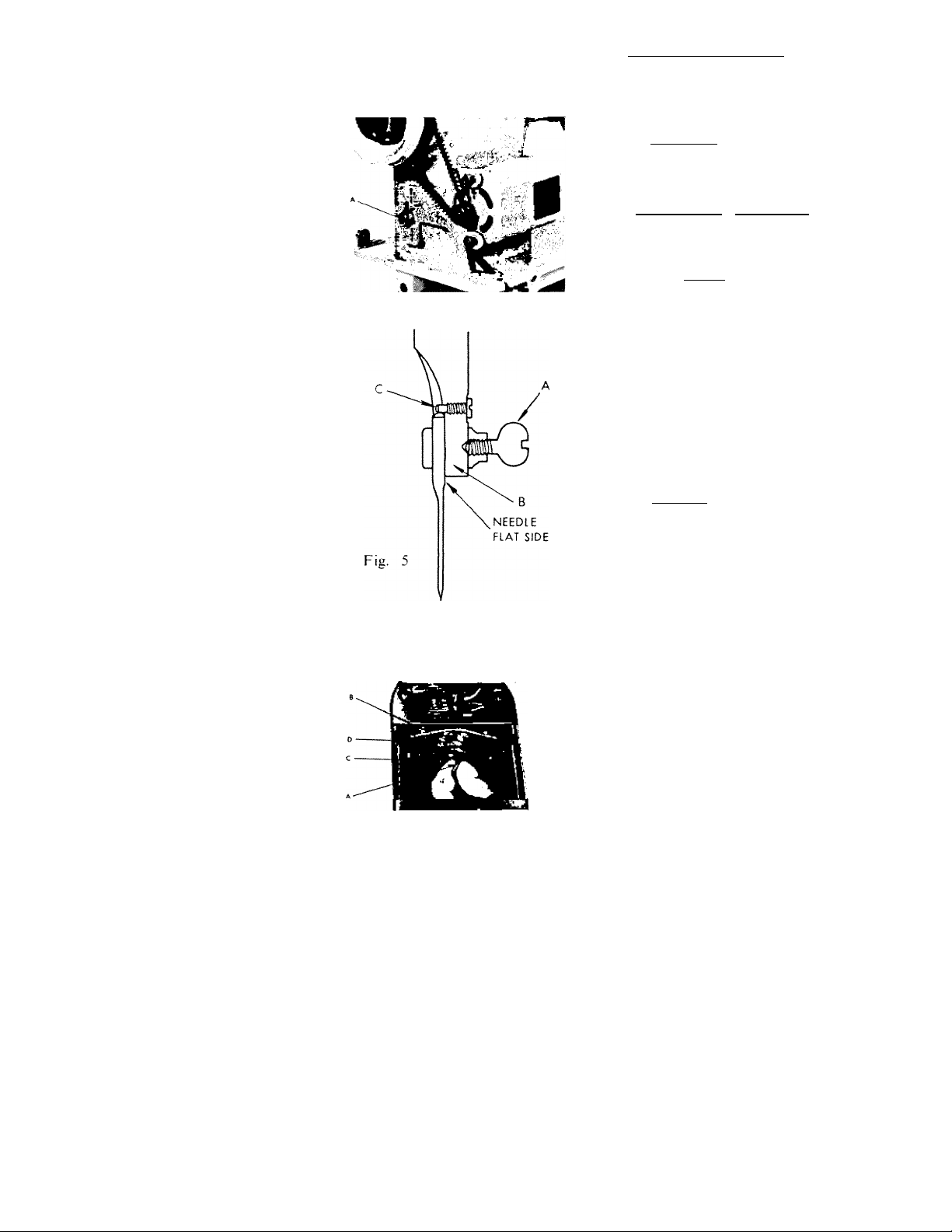
Fig. 4
2. BELT ADJUSTMENT
Loosen motor bracket screw (A).
Slide motor bracket down to tighten
— up to loosen.
CAUTION : Do not tighten belt
too tight.
3 , B E P L A C m e W EED L E
1. Raise the needle bar to its highest
position. (Turn the fly wheel by
hand toward you.)
2. Loosen needle clamp screw (A) and
remove old needle.
3. Insert the needle into needle bar (B)
with the flat side of the needle tow'ard
the fly wheel.
CAUTION : Be sure the needle is
all the way up. It should rest against
the needle stop pin (C).
4. Tighten the needle clamp screw se
curely with screw driver.
CAUTION ; Check needle and make
sure it is not bent or dull.
Fig. 6
4. REMOVING BOBBIN CASE
1. Raise the needle bar to its highest
position. (Turn the fly wheel toward
you by hand.)
2. Open slide plate. With the left
thumb and forefinger, open the latch
(A) of the bobbin case (B).
3. Remove bobbin case from the spindle
post (C). (PuU to the left.)
NOTE : With the latch held open,
the bobbin is locked inside the
bobbin case. To remove bobbin from
the bobbin case, release the latch.
Page 6
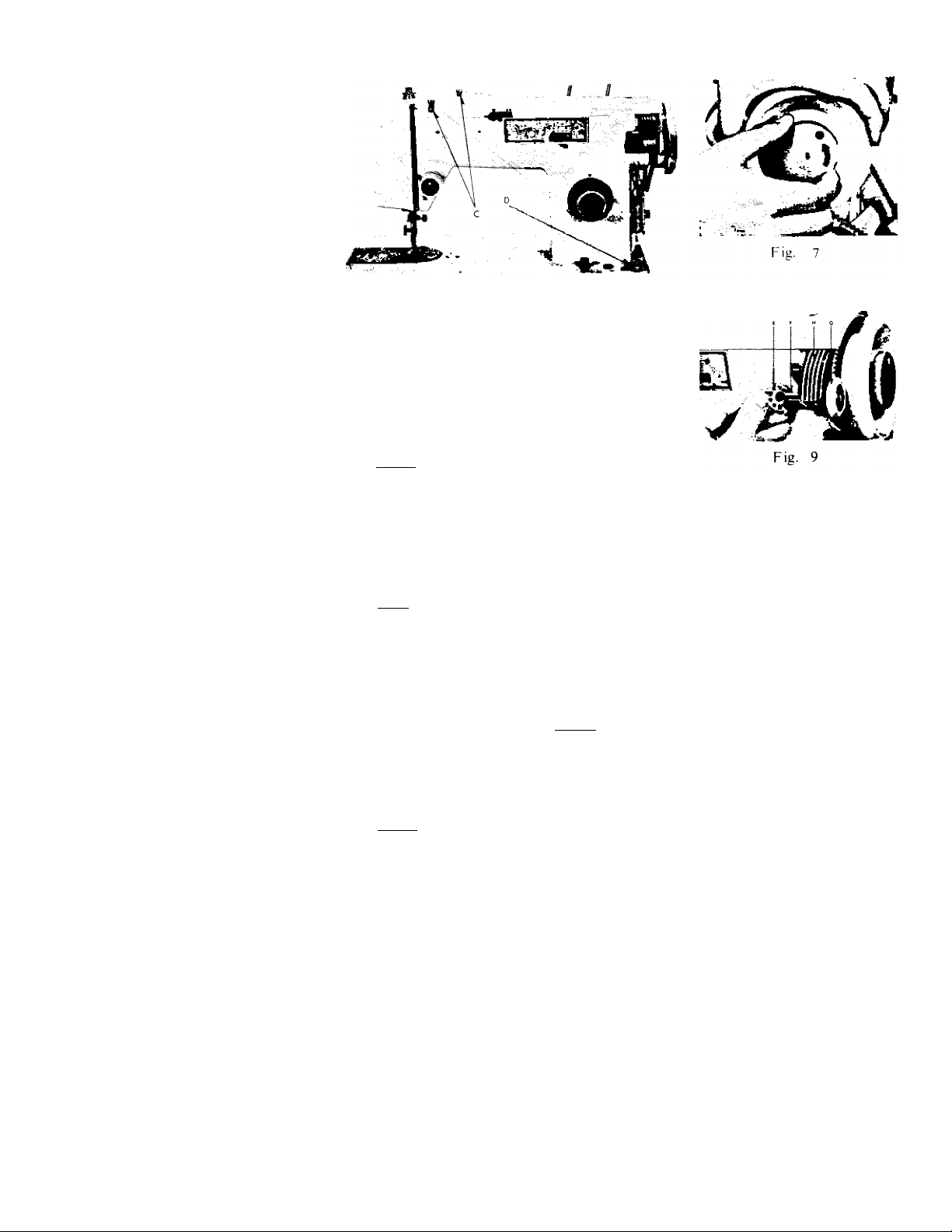
Fig. 8
5. WINDING BOBBIN
1. Hold the fly wheel (A) Fig. 7 with the left
hand and turn the cluch (B) Fig. 7 toward
you to release the clutch. By doing this, the
fly wheel turns freely.
NOTE : If the needle moves, the clutch is
not completely released.
2. Place thread on the spool pin and guide the thread through the upper thread
guide (C) Fig. 8. Then bring the thread across the machine and under the
bobbin winder thread guide (D) Fig. 8.
3. Wind the thread several times on the bobbin (E) Fig. 9. Now place the bobbin
on the spindle (F) Fig. 9 of the bobbin winder.
note : The lock spring on the spindle must fit into the slot in the bobbin.
This is done by holding the rubber ring (G) Fig. 9. with the right hand and
turning the bobbin with the left hand until the lock spring slips into the slot
of the bobbin.
4. Push the cover (H) Fig, 9, of the bobbin winder down until the rubber ring
(G) Fig, 9 is brought in contact with the fly wheel.
5. Turn the fly wheel slowly, toward you; then operate the machine as in sewing.
When the bobbin is full, it will stop.
6. Remove the bobbin from the spindle, then re-engage the machine by holding
the fly wheel with the left hand and with the right hand turn the clutch away
from you.
NOTE : Make sure you tighten firmly.
Page 7
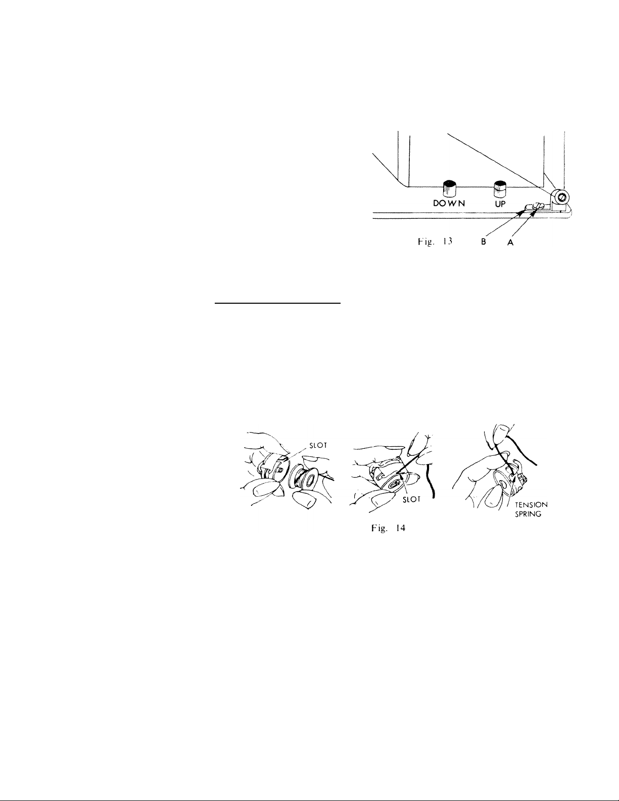
6 ADiUSTINO BOBBIN WINDER
]. If the thread winds unevenly on the bobbin as shown in Fig. 11 and 12, loosen
screw (A) Fig. 13 and adjust the bobbin winder thread guide bracket (B) Fig. 13.
2. If the thread winds as in Fig. 11, move the bracket slightly to the left. If the
thread winds as in Fig. 12, move the bracket slightly to the right.
Fig. 10 Fig- 11 P'K- 12
7. THREADING BOBBIN CASE
1. Hold the bobbin case between the left thumb and forefinger with the slot up.
With 5 or 6 inches of thread trailing in the palm, hold the bobbin between
the thumb and first two fingers of right hand.
2. Insert the bobbin into the bobbin case, then pull the trailing thread into the
slot, up to the left until it enters the delivery eye under the tension spring.
There should be a slight tension on the thread as it pulls through the delivery eye.
Page 8
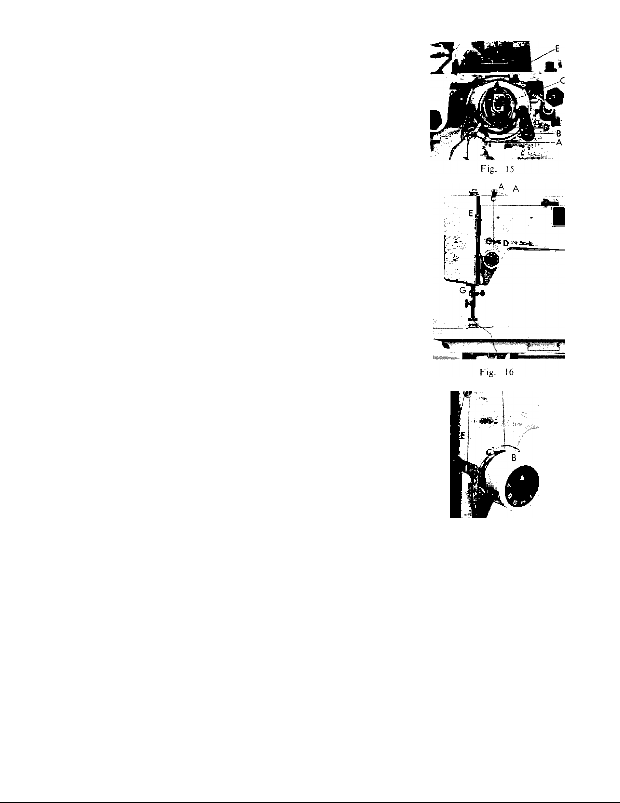
8. REPLACING BOBBIN CASE
1. Turn fly wheel toward you by hand
until the needle bar is at its highest
position, and open the slide plate.
Draw about 3 inches of thread from
the bobbin and let it hang loosely
from the bobbin case.
2. With the left thumb and forefinger,
hold the latch (A) of the bobbin case
(B) and place it on the spindle post
(C) . (Fig. 6)
NOTE ; The protruding finger (D)
must slide into the delivery eye (E)
at the top of the shuttle.
3. Release the latch and press the bobbin
case to the right until it catches the
groove on the spindle post.
9. TH R EA D IN G M A CH I NE
1. Turn the fly wheel toward you and
raise the take up lever (E) to its highest
position. Place thread on the spool pin
and bring the thread through the upper
thread guide (A).
2. Bring the thread down through the
thread guide to the tension disc (B)
from right to left and up. Then pull
the thread up through the thread take
up spring (C).
3. Bring the thread under the thread
tension guide (D) and thread the take
up lever (E) from right to left.
4. Bring thread down through the thread
guide (F) at the opening in the face
plate, and through the needle bar
thread guide (G) from behind. Thread
the needle from left to right, leaving
about 5 or 6 inches of thread.
Fig. 17
Page 9
10. PREPARINO TO SEW
Fig. 18
1. Hold the loose end of the needle thread
in your left hand, and turn the fly
wheel toward you by hand until the
needle moves down through the needle
plate and up again to its highest position.
Pull the needle thread gently, and the
bobbin thread will come up with it
through the hole in the needle plate.
Then place both ends of the thread
back between the toes of the presser foot.
NOTE : If the bobbin thread does
not rise, check to see if there is at
least 3 or 4 inches of bobbin thread
hanging loosely from the bobbin case.
2. Pull the two threads at least 5 inches
behind the presser foot. Place material
under presser foot, and lower the foot
with the presser bar lifter. Regulate
the stitch to the desired size and sew.
TO REMOVE MATERIAL, raise the
needle to its highest position and raise
the foot with the presser bar lifter, then
pull the fabric back and to the left.
Cut the thread with the thread cutter
behind presser bar, leaving a few inches
of thread behind the presser foot.
Fig. 19
Page 10
11. ADJUSTING UPPER THREAD TENSION
The correct stitch can usually be obtained by varying the upper thread tension.
NOTE : TENSION ADJUSTMENT SHOULD BE MADE WITH THE
PRESSER FOOT DOTO.
To increase the tension, turn the tension dial clockwise (Fig. 20). To decrease
the tension, turn the tension dial counter clockwise (Fig. 20). When the tension
is properly adjusted, the upper and lower threads will cross in the center of
the material (Fig. 21-A).
When the upper thread tension is too tight, or the bobbin tension is too loose,
the lower thread will lay flat along the top of the material (Fig. 21-B).
When the upper thread tension is too loose or the bobbin tension too tight, the
upper thread will lay flat along the bottom of the material (Fig. 21-C).
The tension should be adjusted little by little until the desired tension is obtained.
0
Bj
Fig. 20
Fig. 21
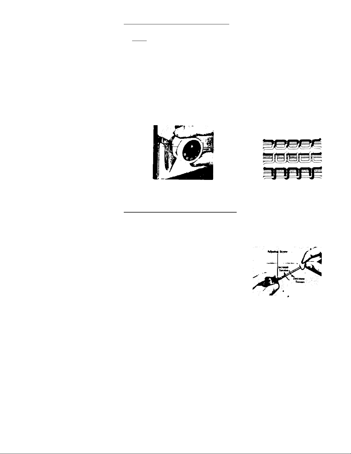
12. ADJUSTING BOBBIN THREAD TENSION .
1. The bobbin thread tension on your machine is correctly adjusted before leaving
the factory. Therefore, it is seldom necessary to alter the bobbin thread tension.
Should it become necessary to do so,
the adjusting screw of the tension spring
on the outside of the bobbin case can
be tightened or loosened to increase or
decrease the tension of the bobbin
thread.
2. To increase the bobbin thread tension,
turn the adjusting screw clockwise.
To decrease tension of the bobbin
thread, turn the adjusting screw counter
clockwise.
Fig. 22
8
Page 11

13. ADJUSTING FABRIC FEEDERS
By using the push buttons you can adjust the fabric feeders for sewing different
types of materials and other special sewing, such as emitroidering or darning.
1. For ordinary sewing, press “UP” button all the way down. (This raises the
fabric feeders to the up position)
2. For sewing very light fabrics, press “DOWN” button half way down so that
the center line of the “UP” button appears on the plate.
3. To lower the fabric feeders below the surface of the needle plate, press the
“DOWN” button all the way down. The fabric feeders are now in the down
position, and you will be able to move your material freely in any direction,
such as when you desire to embroider or darn. When embroidering and darning,
remove the presser foot and use an embroidery hoop.
“UP” Position
Normal Fabrics
DOWN
“MEDIUM” Position
Lightweight Fabrics
DOWN
“DOWN” Position
Embroidering & Darning
DOWN
Fig. 23
&
UP
UP
UP
Fig. 24
14. ADJUSTING PRESSURE OF THE PRESSER FOOT
1. To release the pressure on the material, press down on the curled ring (A). (This
will allow the built-in darner (B) to raise, thus releasing the pressure on the
material.)
2. To increase the pressure on the material, press down on the built-in darner (B).
note : The built-in darner will stop.at any position you desire.
3. For normal sewing, push built-in darner all the way down.
4. For darning and embroidering, release the built-in darner.
CAUTION : Even though the presser foot is removed, make sure the presser
bar lifter is in the down position. ^
5. Adjust the built-in darner to the proper position according to the thickness of
the material you are using.
Page 12

Fig. 25 Fig. 26
15. REGULATING STITCH LENGTH
SEWING FORWARD
The length of the stitch is regulated by the dial, shown in Fig. 27. Near O is the
shortest stitch and 4 is the longest, but the control may be set at any spot between
the marking for a variety of lengths. Turn the dial to the right to lengthen and to
the left to shorten the stitch. The number stitch length you choose is indicated by the
pointer.
SEWING BACKWARD
When you wish to sew backward to tie the threads at the beginning or end of a
seam, press in the button (Fig. 28) as far as it will go. The machine will sew backward as
long as the button is held in.
CAUTION : When the dial is set on the number “O’,’ neither forward nor backward
stitch can be made. This will cause the machine to break the thread.
Fig. 27
Fig. 28
10
Page 13

16. ZIG ZAG SEWING
Fig. 29
REGULATING WIDTH OF STITCH
The zigzag, regulating lever (A) controls the width of the stitch. When you move
the zigzag regulating lever, you will notice that the zigzag indicator (B) moves troiii “O”
to the numbers 1,2, 3, 4 on the zigzag indicator plate (C).
When the zigzag indicator moves the zigzag regulating lever from "0 tow'ard
the numbers 1, 2, 3, 4, the width of the stitch will become progressively wider.
The larger the number the wider the stitch.
note : The zagzig regulating lever returns to the straight stitch position when
released.
11
Fig. 30
Fig. 31
Page 14

L0CKIN6 ZIG ZAG REGULATING LEVER
To lock the zigzag regulating lever
so tliat the machine sews a uniform stitch
width, first move the zigzag regulating
lever until the zigzag indicator is under
the number on the zigzag indicator plate
that you desire.
Turn the zigzag lock coickwise to lock
the position.
CAUTION : Do not release the zig
zag regulating lever until after you have
released the zigzag
screy^
You will notice that the zigzag indi
cator is locked on the number which the
zigzag indicator was set under. If the
zigzag indicator is locked under any
number larger than “O” up to “3M”, you
will notice that when the zigzag regu
lating lever is moved from side to side,
the zigzag indicator will move from that
number to # 4. When the zigzag regu
lating lever is released, the zigzag indi
cator will return to the number under
which it was locked. To release the zig
zag regulating lever, turn the zigzag lock
counter clockwise.
CALJTIOJ^ ; When you turn the zig
zag lock and release screw, do not
hold the zigzag regulating lever.
(Fig. 33)
_____
1 pc^ and release
Fig. 32
Fig. 33
12
Page 15

MAKING.PATTERNS
By moving the zigzag regulating lever front 0-4 as you _are sewing, the pattern
formed will be as in Fig. 34. When you slowly release the zigzag regulating lever
back to its “0” position, you will form the pattern as in Fig. 35. By moving the zigzag
regulating lever slowly from “0” to “4” and slowly back to “0” as the machine is sewing,
you will form the pattern as in Fig. 36.
..
0 12 3 4
Fig. 34
START HERE
You can form the pattern as in Fig. 37 by holding the zigzag regulating lever # 4.
note : The zigzag indicator will be on # 4. You may lock the zigzag regulating
lever in this position (Page 12)
You can form the pattern as in Fig. 38 by moving the zigzag regulating lever
until the zigzag indicator is on # 2. (You may lock the stitch in this position.
See Page 12.)
In order to form the pattern as in Fig. 39, first lock the zigzag indicator on # 2,
then move the zigzag regulating lever so that the zigzag indicator is on * 4. Sew
the desired number of stitches and while the machine is still running, quickly release
the zigzag regulating lever. The machine will now sew a * 2 zigzag stitch. Sew the
number of stitches desired and quickly move the zigzag regulating lever to » 4.
Sew the number of stitches desired and repeat.
0 12 3 4
0 12 3 4
01234 0 1234
mfmmmmmm
13 Fig- 37
Fig. 38
Fig. 39
Page 16

17 . S T RE T CH ST I TC H IN 6
Fis- 42-!
This IS a helpful stitch developed to ada elasticity and strength when sewing on fabrics
III as
It adds triple strength to straight or zigzag stitching. For a triple strength straight st, c -
1. Set stretch control lever “A” at the SS (stretch stitch) position.
T Set ZigZag width control “B” at “0” position.
3 Set stitch length control “C” at * 4- the longest possible stitch. ^ .
To sew multiple zigzag stitches simply engage the zigzag width lever ^e d®sir d
width This zigzag stitch can be used for overcasting, applying elastic waist bands, etc^
Thert are many Ler uses for these stitches which will become apparent as you use
the (M) manual position.
knhs jerseys, etc. It reinforces the garment particularly in stress or strain areas.
to'normal straight or zigzag stitching, move the stretch stitch lever back to
stitch conttoU both the fotward and te.etse stitch length
length control “C” is not set at number 4, the machine will be noisy and the mater
w-ill feed in reverse.
Page 17

You can ronii the pattern as in Fig. 40 by slowly moving the zigzag regulating
lever as the machine is running until the zigzag indicator is on # 4, then quickly
release the zigzag regulating lever and again slowly move the zigzag regulating
lever to « 4, Repeat as often as desired.
In order to form the pattern as in Fig. 41. first move the zigzag regulating lever
to # 4, and while running the machine slowly release the zigzag regulating lever
until the zigzag indicator is on “0”. When the zigzag indicator reaches “0”, quickly
niovc the zigzag regulating lever to # 4. Repeat as often as desired.
In order to make the pattern as formed in Fig. 42. with the zigzag indicator
on “0”. sew a straight stitch for the length desired; then while the machine is still
running, quickly move the zigzag regulating lever to 4. Sew the number oi stitches
desired and then quickly release the zigzag regulating lever. Repeat as often as desired.
0 12 3 4
0 12 3 4
4 0 4 0 4 0
Fig. 42
Fig. 40
note : The above patterns arc just a few of the numerous patterns that you
will be able to make with your machine. By varying the speed with which you
move the zigzag regulating lever and releasing the zigzag regulating lever at the
same time varying the stitch length and; the number of stitches made, you will be
able to create hundreds of different patterns.
CAUTION : When the machine is not sewing, do not move the zigzag regulating
lever unless the needle is raised out of the material. When making patterns, for
best results, the machine should be sewing at a moderate rate of speed.
14
Page 18

18. CLEANING SHUTTLE AND RACE ASSEMBLY
In order to obtain the best possible performance from your machine, it is
necessary from time to time to clean and oil the shuttle and race assembly.
¡removing shuttle
needle, presser foot and needle plate. (See Page 1)
Raise the needle bar to its highest position and remove the bobbin case.
Release knobs (A) on the both sides of the race assembly, by opening them to both
sides and remove shuttle cover (B) from the race assembly.
Take hold of the holder post (C) of the shuttle, and remove the shuttle from
the race assembly.
Carefully clean the race assembly, making sure that you remove any thread
or lint that may become trapped in the shuttle and race assembly. Also thoroughly
clean the fabric feeders (D). This can be done with a stiff brush.
Fig. 44
Fig. 43
REPLACING SHUTTLE IN RACE ASSEMBLY
Raise the needle bar to its highest position.
With the left_ thumb and forefinger, take hold
of the shuttle by the holder post. Turn the
shuttle so that the open ends slide over the
ends of the shuttle driver (E). Gently press in.
Take the race cover in your left hand.
Place ’the race cover over the race assembly
making sure that the two small posts on the
race assembly fit into the small holes on the
race cover. Tighten the both knobs.
Fig. 46
Fig. 45
16
Fig. 47
Page 19

19. OILING THE MACHINE
As in the case with all precision
machinery, it is necessary for maxi
mum efficiency to properly oil and
clean at reasonable intervals. Even
though the machine is not in con
stant use, it is important to oil your .
machine since the oil will dry after
standing over a period of time.
The underside of the machine should
be oiled at the arrow points as shown in
Fig. 48.
NOTE : Before oiling, clean away all
lint or foreign matter. One or two
drops are sufficient at each point.
The machine should be oiled at the
arrow points as shown in Fig. 49. These
parts are accessible by opening the face
plate.
To oil the top parts of your machine,
remove the two screws (A & B) located
at each end of the top cover (C). Remove
top cover and oil the parts located at the
arrow points as in Fig. 50.
NOTE : After you have cleaned and
oiled your machine, it is advisable to
run the machine at high speed so that
the oil will penetrate all moving parts.
CAUTION : After cleaning and oiling
machine, wipe away all excess oil, and
sew on waste material.
20. BUILT IN LIGHT
Fig. 48
Fig. 49
Fig. 50
Your machine is equipped with a built
in sewing light, located inside the face plate.
NOTE ; Face plate is hinged (See
Fig. 51) and opens from left to right.
The sewing light switch is located on
the front of the face plate (See Page 1).
The sewing light is a standard bulb and
can be easily replaced.
17
Fig. 51
Page 20

21. ACCESSORIES
fl:
o
tt "m
Fi . 52
4si
w
I
wm
Button sewing foot
Spool pin felt
Needles (3)
Bobbins (3)
Presser foot for straight stitch
Narrow hemmer
Button hole sewing foot
7
Zipper foot
8
Cloth guide
9
Thumb screw for cloth guide
10
Screw driver
11
Plastic oiler
12
HOW TO USE PRESSER FEET
Your machine is equipped with various specialized feet which will enable you to
do particular jobs with greater efficiency and obtain better results. Whenever you
attach a new foot to the presser bar, make sure you tighten the screw securely with
a screw driver.
18
Page 21

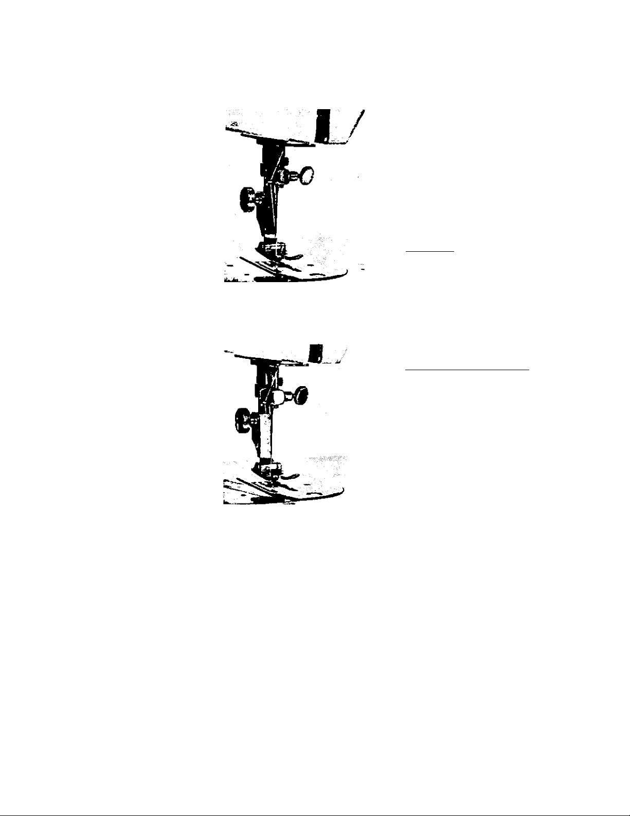
A. PRESSER FOOT FOR STRAIGHT SEWING
When making only straight sewing, it
is necessary to loosen the presser foot
thumb screw and change the presser
foot for zigzag stitch to one for
straight stitch.
CAUTION : Be sure to set the zigzag
indicator at the position of "O”
Fig. 53 A
B. CLOTH GUIDE
Attach cloth guide to the bed of the
machine (See Fig. 53). The cloth guide
will enable you to make a straight stitch
at a uniform distance from the seam.
The cloth guide is adjustable, making it
possible to make a straight stitch at various
distances from the seam.
e, ZIPPER FOOT
Your machine is equipped with an ad
justable zipper foot. Set the zipper foot
on the left side as shown in Fig. 54.
This will allow you to sew on the left
side of zipper without danger of damaging
the zipper or the needle. To sew on the
right side of the zipper, adjust the zipper
foot to the right side by loosening the
screw located on the back of the zipper
foot.
NOTE : When using the zipper foot,
always sew with a straight stitch.
19
Fig. 53
Fie. 54
Page 22

22. BLIND HEMMING
1. Set zigzag indicator on # 4.
2. Set stitch length on largest stitch lo
cated on stitch length indicator plate.
3. Fold the material as shown in Fig. 57A.
4. Turn the fly wheel toward you by
hand until the needle is on the left
side of the zigzag. Place the material
under the presser foot, then adjust the
material until the left side of the fold
is directly under the needle.
5. Make the first stitch by running the
needle through the material by hand,
being very careful to Just barely catch
the folded edge. (See Fig. 57-B) These
stitches should be on the reverse side
of your material. When you open the
folded material, the blind stitch will
be on the front side of your material.
(See. Fig. 57-C)
CAUTION : When making blind hem,
run the machine very slowly. For best
results loosen upper thread tension.
Fig. 57
23. UPP tlQU EING
1. Adjust the machine to a narrow zig
zag stitch.
2. Set the stitch length to smallest stitch.
Baste material on to the article, then
sew around the edges of the material.
21
Fig. 58
Page 23

Fig. 55
?-Thread
BA:
-iD C
2 3 4 5
Fig. 56
Cut
1. Attach buttonhole foot, and set stitch
length indicator on smallest stitch.
(See Page 10)
2. Set zigzag indicator between 1 and
2 and lock into position. (See Paae 12Fig. 32) ^
3. Push “DOWN" button to drop fabric
feeders.
4. Place material under the foot so that
when you start sewnug you will sew
from position A shown in Fig. 56-« !.
Lower the foot on to the material.
Move the zigzag indicator lever until
the zigzag indicator is under * 4 on
the zigzag indicator plate (See Page
11-Fig. 29). Then sew between .A & B
shown in Fig. 56- # 2 and make 4 or 3
stitches.
5. Raise the fabric feeders to up position.
Release zigzag regulating lever so that
the indicator returns to the position
between 1 and 2. ^
6. Sew from A to C shown in Fig. 56- # 3.
With the needle half way through the
material on the left side of the zig
zag stitch (Fig. 56- # 3E), using lire
needle as a pivot, turn the material in
the opposite direction.
7. Lower the fabric feeders as in step # 3.
Turn the fly wheel toward you by
hand until the needle is at its highest
position. Move the zigzag regulating
lever until the indicator is under # 4.
(See step # 4). Sew from C to D as
shown in Fig. 56- # 4. Release zigzag
regulating lever so that the zigzag
indicator returns to the position between
1 and 2.
8. Raise fabric feeders and sew between
D and B as shown in Fig. 56- ^ 5.
CAUTION : Sew between D and B
carefully, being carefull not to overlap
the two sides of the buttonhole.
9. With the ripper, cut the cloth between
the two sides of the buttonhole. (Fig.
56- # 5,
20
Page 24

24. EMBROIDERING AND MONOGRAMMING
!. Release pressure of presser toot. Lower
fabric feeders. Lock zigzag indicator
into posiiion "Z” under the zigzag
indicator plate. Put material into em
broidery hoop, then place under foc-t.
Lower foot, then turn the fly wlicel
toward you. by hand and raise the
lower thread through the material so
that both the upper and lower threads
are on top of your material.
2. Sew' at medium speed. Move niuterial
slowly so that the thread will be close
together as in a satin stitch. With a
little practice you will be able to do
many types of designs and gain a great
deal of pleasure from your machine.
Fig. 59
CAUTION: Work carefully and be sure
to keep fingers out of the path of the
needle.
25. DARNING
1. Release the pressure of the presser
foot. Lower the fabric feeders, and
place the material under the foot and
lower the presser bar.
note : This enables you to move
the material in any direction while
the machine is running.
2. Sew around the areas you desire to
darn. Then move the material back
and forth, sewing out beyond the worn
or open place in the material. Con
tinue until the hole is covered, going
Fig. 6 0
both sideways and forward and back,
note : While darning, run the machine
at medium speed.
Page 25

26. SEWING ON BUTTONS
1. Remove hinged presser foot and attach button sewing foot. (See Fig. 61)
2. Push drop feed button “DOWN” all the way. (Fig. 65).
3. Set zig zag stitch width at 0. Place the button so that its left hole comes
directly under the needle, then gently lower the presser foot. (Fig. 62)
4. Move zig zag stitch width until the needle comes down exactly over the
right hand hole in the button and lock zig zag position. (Fig. 63) Turn the hand wheel
slowly by hand to be sure the needle enters both holes in button without deflecting
needle, correct width if necessary.
5. When needle goes into the center of each hole, run the machine at medium
speed, making six or eight stitches, stopping with the needle in the left hole.
6. To lock the zig zag stitch and prevent ravelling, set the stitch width at 0, and take
a few stitches in the same hole. If you wish you may place a rounded toothpick
over the button, between the two holes, and sew button to fabric in regular way.
Remove the toothpick and wind thread under the button, forming a shank to
fasten.
Apply the above method to sew on buttons with four holes, hooks and snaps,
etc. If a four hole button is to be sewn, follow the same procedure as for the two
hole button.
Now lift presser foot slightly and move fabric to permit stitching the remaining
two holes, Hooks, snaps, etc., are sewn to the fabric with the same procedure as for
sewing two hole buttons.
23
Fig. 62
Fig. 64
Fig. 61
1
• a
DOWN U f*
Fig. 65
Fig. 63
Page 26

91. CAUSES OF COMMON DIFFICULTIES
note : Clean and oil machine at regular intervals.
Machine Makes Noise
1. Thread jammed in race assembly. (Clean and oil shuttle and race assembly )
2. Blunt needle.
3. Needle plate not placed in properly.
4. Slide plate not all the way to the right.
B. BREAKING UPPER THREAD
1. Incorrect threading.
2. Upper thread tension too tight.
3. Lower thread tension too tight.
4. Fautly needle, or needle placed incorrectly.
5. Needle brushing against presser foot or other attachments.
6. Needle eye too small for thread used.
7. Starting the machine suddenly or with a jerk.
8. Starting the machine with the take up lever at its highest point.
9. Presser bar not lowered.
10. Thread jammed in race assembly. (Clean)
C. BREAKING THE LOWER THREAD
1. Incorrect threading of the bobbin case.
2. Lower thread tension too tight.
3. Bobbin wound too full or improperly.
4. Rough edge in hole of needle plate.
BREAKING THE NEEDLE
D.
1. Pulling or holding the fabric while machine is running.
2. Using bent needle.
3. Needle not set in securely. (Tighten needle clamp screw with screw driver)
SKIPPING STITCHES
E.
1. Using bent or blunt needles.
2. Needle inserted incorrectly.
3. Needle threaded improperly.
4. Using wrong size needle. (Length - Use 15X1 needle)
5. Pressure of presser foot insufficient, especially when sewing heavy material.
F. UNEVEN STITCHES
1. Presser foot not resting evenly on material.
- 2. Fabric feeders not high enough.
3. Stitches too short.
4. Pulling or holding the cloth while machine is running.
5. Using too fine a needle with too coarse a thread.
6-. Upper and lower thread tensions not adjusted properly.
Page
9
10
Page 27

I
■щ
ъ
■э
<5
Page 28

51021
1
1
51032
'I
i
A
51050
5
5-1
51968
6
51033
7
8
51031
9
10
51415
11
12
51135
13
14
51116
15
16
51420 Thread tension regulator (unit) 57 51356
17
18
56011
19
51411
20
21
TT
51401
23
24
51061
25
26
56062
27
28
29 132
56041
30
31
32
51440 Bobbin winder (unit) 7 ?77(s
33
34
35
51108
36
37
38 Ilio
39
51800
40
Face plate
Face plate set spring
Washer for 4
703
Set screw for 2 43
112
Lamp assembly 44
Set screw for lamp socket
191
Bulb
Lamp bracket
Set screw for 7
131
Face plate hinge
Set screw for 9
131
Thread guide plate
Thread guide plate set screw
310
Thread loose metal
Thread loose metal hinge screw 54 56234
510
Needle bar crank rod guide^^^3
Set screw for 15 3 70 y
112
445
Set screw for 17
Top cover '7 59 51357
Thread guide for top cover
310
Set screw for 20
170
Top cover set screw 61
Spool pin base (unit)
132 Set screw for 23
Cord set metal
131
Set screw for 25
Cord set metal (2)
1460
Bobbin winder tension bracket
(unit)
Set screw for 28
Machine number plate
680
Lead pin. 1.7
301
Name plate set screw
1455
Bobbin winder rubber ring
162
Set screw for bobbin winder
Fly wheel y^ ~7 7 J
1109
Fly wheel clutch stop washer
Fly wheel clutch
220
Clutch nut set screw
Sewing machine motor
51815
40-1
41
42
51819
51069
45
46
51230
47
51220
48
49 320
51232
50
51 51231
52
53 112
51233 Reverse stitch button
55
56 445
58
60 51360
51359
62
63 704
64 51358
65 690
513.54
66
51353
67
51501
68
69
70
51502
71
51570
71-1
51582
71-2 920
71-3
51583
714 690
72
Plug
Motor setting screw
180
Motor set screw washer
720
V belt for motor
Cord bush
Hinge set screw
270
Feed indicating pin
680
Cover for number plate
Feed regulating device (unit)
Feed regulating device set screw
Stitch length indicator plate
Stitch length control dial knob
703 Washer, 3 x 8 .x 0.5
Set screw for 51
Reverse stitch button spring
Set screw for 55
Zig Zag slide metal ~7 ^ K'J
Set screw for 57
510
Slide metal spring ~7 H 762>
Base plate for Zig Zag indicator
plate
920
Nut for 60
Zig Zag indicator plate
Washer, 4 X 10 x 0.8
Zig Zag lock and release screw
Split pin, 1.0 X 10 7^7/S'
Zig Zag regulating lever
Zig Zag regulating lever knob
Needle plate for Zig Zag stitch
340 Needle plate set screw
Slide plate (unit)Drop feed (unit)
Drop feed connecting rod
Nut for 71-1
Drop feed control button
complete
Split pin for 71-1
131
Set screw for 71-3
Page 29

Page 30

51132 Presser bar spring
51130 Presser bar guide bracket
73
f4
l5
16-
ir
fi
%
470 Set screw for 74 ^
«1131 Presser bar lifter 33 /S
612 Spring pin for 76 33/1*
1133 Thread cutter
732 Presser foot thumb screw
51134 Presser foot for Zig Zag stitch
51150 Presser release (with bushing)
81,
51170 Needle bar supporter (unit)
82
1122 Needle bar
82-1
11 23 Presser bar
82-2
«1175 Presser bar bushing (lov^£i.^:i^i/
82-3
83
84
85
86
87
SS
89
90
91
91-1
92
92-1
92-2
93
94
95
96
97
98
98-1
445 Set screw for presserjla^ushing
444 Set screw for 83
51338 Needle bar connecting rod pin ^
753 Snap ring 3 for 85 33/^
1126 Needle clamp (unit)
Needle (No. 14)
51129 Needle bar thread guide
201 Set screw for needle bar thread
guide
51117 Needle bar crank rod (unit)
51119 Needle bar connecting stud
51111 Thread take-up lever (unit)
51114 Thread take-up lever link pin
51115 Needle bar crank
478 Needle bar crank set screw
• 51106 Thread take-up balance
612 Spring pin 3.5 X 22
51105 Arm shaft bushing
56102 Arm shaft
51301 Zig Zag cam (unit)
51104 Arm shaft screw gear with set 129-1
screw
99
100
101
102
103
104
105
445 Set screw for 98
56600 Worm
444 Set screw for 100
51103 Feed cam
472 Feed cam set screw ■
475 Arm shaft bushing set screw
51107 Fly wheel bushing
106
107
108
109
109-1
110
51201
Spring pin 3.5 X 18
6J2
Set screw for 92-1
445
Forked rod
Forked rod hinge screw
571
970 Nut for 109
Feed connecting slide block
1202
(unit)
110-1 1204
Feed connecting slide block
screw '
111
112
51205
51208
Feed regulater
Feed regulating plate (unit)
113 114 Feed regulating screw
114
51210
115
116
56211
117
51212
118
119
120
120-1
121
51310
121-1 51320
122
123
51321
124
Feed regulating screw spring '
Washer for 107 (STW FM 6.0 x 1.0)
730
Feed regulater spring
Feed regulater hinge pin
Set screw for 117
142
Crank connecting rod
1160
Crank connecting rod hinge screw
581
Nut for 120
980
Zig Zag origin (unit)
Zig Zag origin slide block
Set screw for 121
142
Zig Zag width adjustor 33
Zig Zag width adjustor hinge
570
/
screw 3 70'Z^
125
51322
Zig Zag width adjustor stopper
(1)
126 51323
Zig Zag width adjustor stopper 7^*^
(2)
127
131
Set screw for 126 "7 9 9 ¥7
128 51324 Zig Zag width adjustor spring
129 51330 Vertical shaft link (unit)
51336
130 51337
131
51339
132
51350
133
134
135
56601
Zig Zag width adjustor collar
Needle bar connecting rod 33 fi
Vertical shaft
Zig Zag regulating plate (unit) .
131 Set screw for 132
Set screw for 66
112
Stretch stitch control device
(unit)
135-1
56708
Stretch stitch control stopper
Page 31

135-2
136
137
138
139 131 Set screw for 138
140 56258 Feed change rod pin
141
142
143
144
145 471
146
147
148
149
150
151
152
153 51514
154 444
155
156 51516
157
158
159
160 51518
161
162
162-1
163
164
165
166 1530 Feed rock shaft
167
168
169
170 52533
171
172
56709
56250
56259
481-N
51505
51506
51510
51511
51515
51517
51520
51555
51521
51522
1529
51531
51532 Feed bar
480 Feed bar center screw with
112
1544
Stretch stitch control knob
Set screw for 135
142
Set screw for 135-1
320
Feed change linkage (unit)
S.S. connecting rod
753
Snap ring 3 for 141
Center screw with nut
481
Center screw (without nut)
Set screw for center screw
721
Loose pro tec ter
OscOlating rock shaft -lO
Oscillating shaft crank (unit)^ n
444
Oscillating shaft crank set
screw (L-3.7)
611
Spring pin 3.0 X 16
Lower shaft
Shuttle driver (unit)
Lower shaft stop collar
Set screw for 153
Race connecting rod
Race connecting rod pin
755
Snap ring 5 for 156
126
Race connecting rod pin
set screw
Race guide with screw
Race guide shaft
142
Set screw for 160
Shuttle race (unit)
Race cover complete
Shuttle hook
Bobbin case
Bobbin
Feed rock shaft crank with
screw
nut
Feed dog
Feed dog set screw
Feed lifting rock shaft
ACCESSORIES f
1
1905 Spool pin felt
2
1910 Sewing Needles, No. 14
(3 pee. in a package)
3
1529 Bobbins
4
51924 Pressuer foot for straight sf
5
51925 Narrow hemmer
6
51926 Button hole sewing foot
7
51927 Button sewing foot
8
51928 Zipper foot
9
1942 Cloth guide
1943 Thumb screw for cloth guide
1961 Small screw driver .
12
1962 Large screw driver
13
1965 Plastic oiler
14
1969 Accessory box
Page 32

MEMO
 Loading...