

Page 1
STRUCTION BOOK
IN
Page 2

foreword
Your sewing machine is the product
of mony years of research and
developmer.t in the field of house
hold sewing machines. It is the
ultimate in efficiency, quality and
design, yet its moving and wearing
parts, such as needles, bobbins,
bobbin cases hooks, etc., are
standard and interchangeable with
parts immediately available at
sewing machine stores the world
over.
This precision sewing head, simpli
fied and many labor saving extras,
is the result of our constant effort,
and each machine is built the most
exacting specifications under our
rigid quality control program.
The furniture and attachments are
made by affiliated factories under
our main factory while complete
units are assembled and recheck
ed by our specialists in our factory
strictly.
FMEWORD
Page 3

Note:
Use standard 15 x 1-needles
available at any sewing ma
chine store.
J
-
Fig. 1
To replace the needle, raise the needle
bar to its highest point by turning the
balance wheel (Rg. 3) TOWARD YOU
by hand. Loosen the needle clamp screw
(A) on the right hand side and the needle
damp will open, allowing the old needle
to fall out.
Remove the old needle and slide the
new needle up (FLAT SIDE TOWARD
THE BALANCE WHEEL) as far as it will
go, when the needle hits the stop it is
in position correctly. Now fasten the
needle clamp securely. For best results
change needles frequently.
needles and thread
Never use a bent needle, nor one with a
blunt point, since this causes imperfect
stitches and may cause the needle to
break. Unless the needle is in CLEAR
TO THE STOP, FLAT SIDE TOWARD
THE BALANCE WHEEL, the machine will
be out of time, and skipped or imperfect
stitches will result and needles may break.
The size of the needle should conform
to the size of the thread and both should
be suitable to the material. Use a needle
sufficiently large to permit the thread to
pass freely through the eye. In general
sewing, use the same size thread in the
bobbin as is used on top.
Page 4
, Fig. 2
Important:
In the following operations
the needle must always be
above the surface of the
machine.
Raise the needle by turning
the balance wheel TOWARD
YOU by hand.
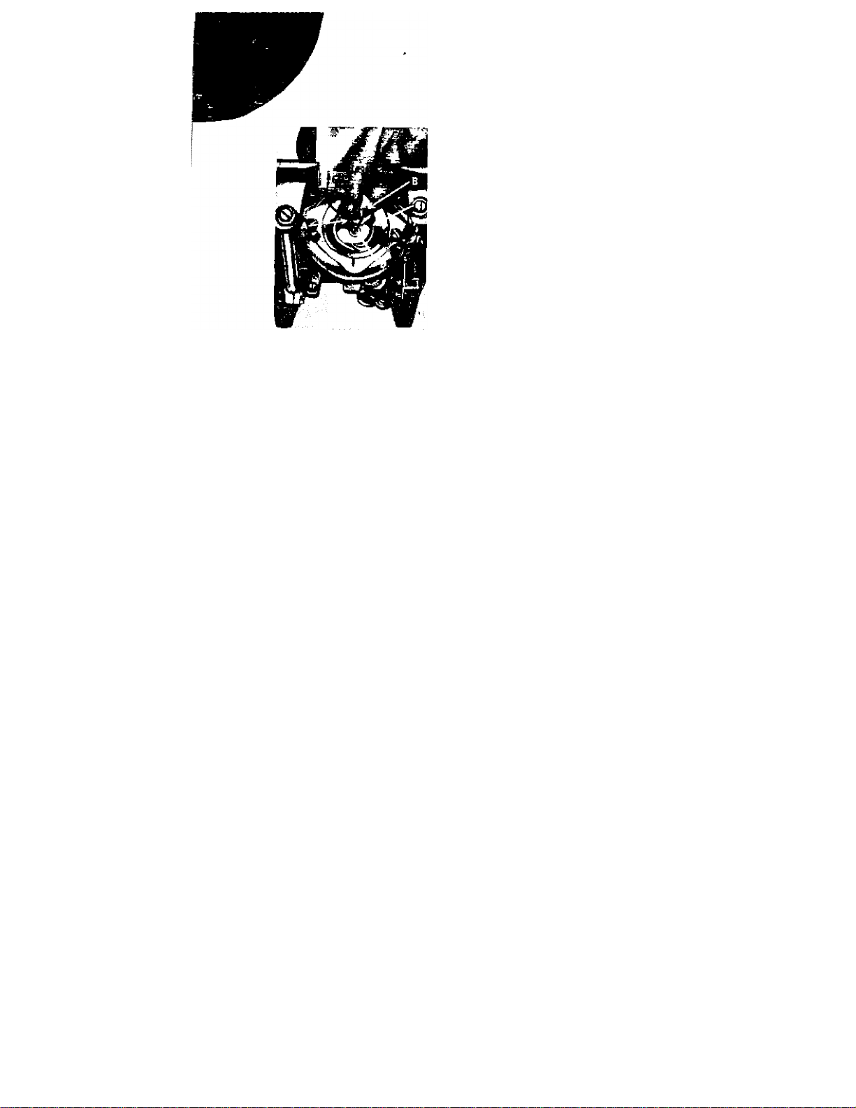
TO REMOVE THE BOBBIN CASE
Open the window for removing bobbin case
located in the left side of the Oil Re
ceptacle. With left thumb and forefinger
open the latch (A) and hold securely as you
withdraw the bobbin case from around the
holder post (D).
On releasing the latch and turning the
bobbin case downward, the bobbin case
drop out.
TO INSERT THE BOBBIN CASE
After winding a fresh bobbin and threading
the bobbin case (see pagas 8, 9, 10 and
11), hold the case latch with left thumb
and forefinger, (as explained above) to
prevent the bobbin from falling out.
Keeping protruding finger (B) topside to
ward the delivery eye (C), press the
bobbin case around the holder post until
the finger (B) enters the delivery eye and
the latch mechanism catches the groove
near the end of the stud. This operation
is easy NEVER FORCE IT. Three or
four inches of the thread hanging free
from the bobbin case will be brought up
through the needle plate stitch hole as
shown on page 12.
Page 5
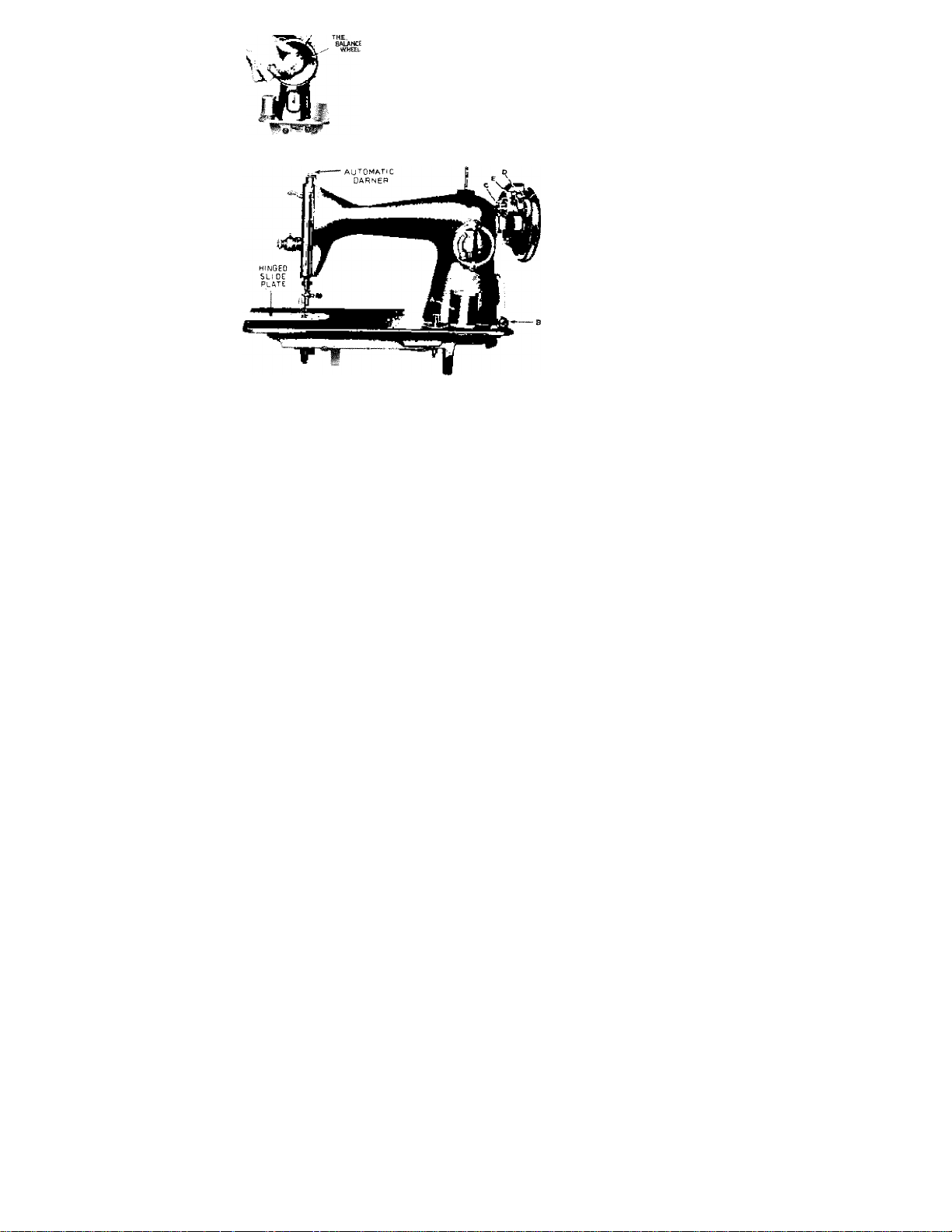
Fig. 3
Fig. 4
NOTE: This machine uses standard 15
class bobbins available at all sewing
stores. The bobbin can be wound
while machine is in operation by not
releasing the stop motion knob as de
scribed in below paragraph. Therefore
needle and bobbin winder will operate
at the same time.
Holding the balance wheel with the left hand,
turn the stop motion knob toward you. This
will permit tne balance wheel to turn freely
while the needle bar remains motionless.
Place a spool of thread on the spool (A).
Pass the thread through the tension disc (B)
at right corner of the base of the machine.
Now wind the end of the thread around an
empyt bobbin seven or eight times and place
the threaded bobbin on the spindle ‘(C) of
t^’e bobbin winder. Press the bobbin into
the spindle with the left hand, making sure
that the PIN on the spindle fits into the
SLOT in the bobbin. Push the bobbin winder
lever (D) down until the small rubber wheel
presses against the hub of the balance wheel
and the clasp (E} falls between the sides of
the bobbin, holding it in position. Turn the
balance wheel toward you and proceed to
operate the rheostat control, as in sewing,
when the bobbin is full, it will release auto
matically and stop turning. Break off the
thread and detach the bobbin from the spindle.
Hold balance wheel firmly with left hand and
with right hand turn the stop motion knob
away from you until the machine is tight and
the needle bar moves with the turning of
the balance wheel.
Page 6

Fig. 5
Fig. 6
10
Fig. 7
Hold the bobbin case between the
left thumb and forefinger with the
slot up. With 5 or 6 inches of
thread trailing in the palm, hold
the bobbin between the thumb
and two fingers of the right hand.
(Fig. 5)
Insert the bobbin into bobbin case
and pull the trailing thread into the
slot, down and to the left until it
enters the delivery eye under the
tension spring. (Fig. 6)
There should be a slight tension oil
the thread as it is pulled through
the delivery eye and the bobbin
should unwind freely. The tension
may be increased by turning the
tension screw to the RIGHT and
decreased by turning the screw to
the LEFT. (Fig. 7)
11
Page 7

Fig. 8-A
1. Place a spool of thread on spool pin (A)
and lead the thread through the notched
thread guide (A) on the face plate.
2. Run the thread through the tension discs
(C) FROM BACK TO FRONT.
3. Draw the thread up over the tension bar
(D) and through the wire check spring (E).
4. Now take the thread up through the eye
of the take-up lever (F) and down through
the thread gui des (G and H).
5s Thread the needle from left to right, pull
ing about six inches of thread through the
eye of the needle (1).
1. Place a spool of thread on spool pin (A)
and pass the thread to the left through
thread guide (.B).
2. Lead down from right to left between
tension discs (C).
3. Draw the thread up into the take-up spring
(E) until the thread enters the retaining
fork (D).
4. Now pass the thread through the hole of
thread take-up lever (F), and down to the
guide (G) on face plate.
5. Then lead into the wire guide (H) on the
needle clamp and thread the needle from
right to left, drawing about six inches of
thread through the eve of the needle Cn,
13
Page 8

Fig. 9
14
Thread machine
Pick up bobbin thread as follows;
Holding the loose end of the
needle thread in your left hand,
turn the balance wheel toward you
by hand until the needle moves
down and up again to its highest
point. Pull the needle thread
gently and the bobbin thread will
come up with it through the needle
hole (Fig. 9). If the bobbin thread
does not rise, check to see if at
lest 3 or 4 inches of bobbin thread
is hanging loosely from the bobbin
THEN PLACE BOTH ENDS OF
THE THREAD BACK BETWEEN
THE TWO PRESSER FOOT TOES
(A) (Fig. 9).
15
Page 9

Fig. 10
With the needle raised and the
threads drawn back, at least 4
inches through the toes of the
presser foot, place the material to
be sewn beneath the presser foot,
and lower the presser foot lever
as far as it will go. Insert needle
into material by turning the balance
wheel TOWARD YOU from top
down, by hand. Regulate stitch to
desired size (see page 21 ) and start
sewing.
Do not try to help the feeding of
the work by pulling the material,
as this may bend the needle and
cause it to blunt or break. As the
machine feeds without any assist
ance, it is sufficient merely to guide
the fabric gently, by hand in the
direction you want it be sewn.
To Remove the Work
Stop the machine by releasing the
pressure on the rheostat control
and stopping the balance wheel
with the right hand. Raise the
needle to its highest point and
raise the presser foot by lifting
the presser foot lever with either
hand. Now draw the sewn
fabric back and to the left about
eight inches and break or cut the
trailing threads.
Page 10

NON-
JAMMIHG
FEATURE
Fig- ITi
One of the outstanding engineering innovations incorporated in this machine eliminates,
for all practical purposes, the age old problem
of jamming.
Other round bobbin, oscillating machines tend
to jam, or freeze, when thread is impropetly
introduced into the race assembly. This
nitroduction of alien thread is usually the
result of sewing without material tn the ma
chine or of turning the balance wheel back
wards while the machine is threaded.
Should this happen while you are using your
machine, the thread will simply break and,
by the action of a scientifically cut hook.
18
the thread will be swept out of the race and
the machine freed almost instantly. The ma
chine may seem to become stiff for a
moment. Do not be afraid to free the ma
chine by turning the balance wheel TOWARD
YOU by hand.
Your dealer will be happy to show you the
operation of the precision engineered single
screw race assembly and to explain the action
of the cut hook in preventing jamming.
OTHER EXCLUSIVE FEATURES
Automatic Darner i A new design with a
self adjusting spring loading mechanism. By
pressing the release spring the pressure bar
foot is relieved so that you may darn, mend,
embroider or monogram. (Fig. 4, page 8.)
Deck Drop Feed : By turning this device
to DOWN position the machine can be made to stop
tV feeding automatically and
f * ; t;,g material guided by hand.
Used with the automatic
darner, this will make darn
ing, monogramming, etc. much easier. The
special, exclusive adjustment for SILK makes
it possible to sew this fine material without
snagging.
Hinged Slide Plate: This exclusive improve
ment makes it possible to reach the bobbin
case easily by giving you much more hand
room than in any other machine. (Fig. 4, page
19
Page 11

Fig. 12
20
Your machine can be adjusted to
sew from 7 to 30 stitches to the
inch, forward or reverse, as desired.
To adjust the stitch length, move
the lever (A) to the center, or
neutral position. Loosen thumb
screw (B) and move it up. When
the thumb screw is in its lowest
position, a 7 will appear in one of
the two windows at the right. As
it is moved up, toward the top,
the numbers 1 2, 1 5, 20 and 30 will
appear in the windows. These
numbers indicate the number of
stitches per inch, 7 being largest
and 30 the smallest stitch practical
for home sewing.
As the desired stitch setting ap
pears, tighten thumb screw, thus
automatically locking the adjusting
plate.
To sew FORWARD, pull lever (A)
down as far as it will go. To sew
REVERSE, push lever (A) up as
far as it will go. You can sew the
same size stitch forward or reverse,
by merely flicking lever (A) down
or up.
Never sew in the neutral
position (0-Fig. 12)
21
Page 12

For perfect stitching, the tension
on the upper and under threads
should be equal, and just sufficient“
ly strong to lock both threads in
the center of the work (A)
(A,) Fig. 13
If the tension on the needle thread
is too tight, or if that on the
bobbin thread is too loose, the
needle thread will lie straight along
the upper surface of the material,
making an imperfect stitch (B).
Fig. U
If the tension of the bobbin thread
is too tight, or if that on the nee
dle thread is too loose, the bobbin
thread will lie straight along the
under side of the material, making
an imperfect stitch (C).
Regufating the Neecife Tension: Minor
imperfections in the stitch can usually
be corrected by varying the needle
tension only.
To increase the tension, turn the thumb nut
(diagram) clockwise; to lessen the tension,
turn the nut in the opposite direction. The
tension adjust from 0 to 9 in one 360 turn,
with 0 being the lightest tension and 9
being the tightest. All adjusttr.ents should
be made gradually, not abruptly, and the
required tension setting will vary with the
size of thread being used. A little practice
will make instant tensio.n adjustments possible.
All adjustments should be made while the
presser foot is down since an automatic
release does not permit adjustments to be
made when the foot is up. If a perfect
stitch cannot be obtained by adjusting the
needle thread tension, it may be necessary
to adjust the bobbin thread tension as ex
plained on page 10, Fig. 7. This mach.ine is
correctly adjusted before leaving the factory
and checked and readjusted before the dealer
delivers it to you.
A careful regulation ot the tensions on this
machine will assure you of the finest seams
that mechanical design will produce.
23
Page 13

Pig. 16
A sewing machine never needs
grease. All moving parts which
come in contact with others, must
be covered with a film of oil, and
should not be allowed to become
dry. Oil, when necessary, should
be applied at the points indicated
by the arrows in Fig. 16, a drop
of oil being sufficient at any one
place. Oil should be applied
freely at all contact points on the
underside of the machine. A few
drops of oil in the bobbin race
will help your machine to run
freely.
When oiling, insert the oil can
nozzle well into oil holes.
After oiling, run the m.achine
rapidly for a fe w minutes, so that
the oil may penetiate into the
bearings. For the proper care of
your machine oil -frequently.
Neglecting to do this tends to
shorten the life of the machine,
and may cause trouble and an
noyance.
Page 14

SEWING MACHINE PARTS
-■¿■i ■ 1 «& ■
a 115
Page 15

1 Main Shaft
2 Thread Take Up Cam
3 Stud Screw ar^d Nut for Thread
Take Up Cam
4 Thread Take Up Cam Screw
5 Main Shaft Bearing
6 Main Shaft Bearing Set Screw
7 Counter Balance
g Counter Balance Set Screw
9 Feed Cam
10 Feed Cam Set Screw
11 Balance Wheel Bushing
12 Washer for Stop Motion Screw
1 3 Clamp Stop Motion Clamp Screw
14 Stop Screw for Clamp Screw
15 Cap for Thread Take Up Lever
Hoie
16 Taper Pin for Balance Wheel
Bushing
17 Thread Take Up Lever Stud
Screw
18 Thread Take Up Lever Assembly
19 Darner
20 Presser Bar Spring Bracket
21 Presser Spring
22 Presser Bar
23 Presser Foot
24 Presser Foot Thumb Screw
25 Oil Cap for Needle Bar
26 Needle Bar
27 Needle Clamp
28 Needle
29 Needle Bar Thread Guide
30 Thread Cutter
iCey NO.
31
32
33
34
35
36
37
38
39
40
41
42
43
44
45
46
47
48
49
50
51
52
56
57
58
r'arts rvame
Set Screw for Needia Bar Thread
Guide
Taper Pin for Lower Shaft Crank
Needle Bar Bearing
Needle Bar Connecting Link
Needle Bar Stud
Forked Connecting Rod
Peed Forked Connecting Hinge
Screw with Nbit
Crank Rod
Rock Washer
Slide Block for Feed Regulator
Stude Screw for Feed Regulator
Slide Block
Feed Regulator
Set Screw for Hinged Stud
Screw
Hinged Stud Screw for Feed
Regulator
Crank Rod Taper Screw with Nut
Set Screw for Lower Shaft Crank
Lower Shaft Crank
Lower Shaft
Shuttle Driver with Spring
Presser Bar Lifter Pin
Piesser Bar Lifter
Set screw tor Presser Bar Liiter
Pin
Slide Roller and Stud for Drop
Feed Bracket
Peed Bar
> Feed Dog
Feed Dog Set Screw
Toper Center Screw for Feed Bor
Taper Center Screw with r,ut
Key No
59
60
61
62
63
64
65
66
67
68
69
70
71
72
73
74
75
76
77
78
79
80
81
82
83
84
85
86
87
90
Parts Name
Oscillating Rock Shaft
Lower Shaft Crank Slide Block
Horizontal Feed Rock Shaft
Vertical Feed Rock Shaft
Drop Feed Connecting Rod
Drop Feed Plate
Drop Feed Bracket Assembly
Drop Feed Plate Screw
Drop Feed Knob
Drop Feed Rod Bearing
Cutter Pin
Hinge Stud for Drop Feed Con
necting Rod
Drop Feed Rod Spring
Drop Feed Knob Rod
Shuttle Race
Shuttle Hook
Bobbin Case
Bobbin
Shuttle Race Screw
Needle Plate
Slide Plate Spring
Slide Plate
Spring Screw
Needle Plate Set Screw
Face Plate Assembly
Face Plate Screw
Upper Thread Tension Knob
Tension Dial
Cap Washer for Tension Dial
Upper Thread Tension Spring
Cap for Tension Dial
Thr«i"d W/--!-
Thread Take Up Spring
92
Tension Stude
93
Tension Release Pm
94
Arm Slide Plate
95
Arm Slide Plate Screw
96
Stitch Dial Plate
97
Limitting Plate for Feed Regula
98
tion
Stitch Dial Lever and Nut
99
Stitch Dial Plate Screw
100
Balance Wheel
101
Fixing Screw and Washer
102
Limitting Plate
Washer for Fixing Screw
103
Ball Oiler for Bobbin Winder
104
Bobbin Winder Assembly
105
Bobbin Winder Set Screw
106
Name Plate Screw
107
Tag P’*'^
108
Head Set Screw for Head Hinge
109
Bobbin Winder Rubber Wheel
no
Cord Bushing
111
Bobbin Winder Tension Bracket
112
Assembly
Set Screw for Bobbin Wmder
113
Tension Bracket
V Belt ,
114
Dial Tension for Bobbin wmder
115
Accessories Box
116
Oiler
117
118
119
120
121
122 Spool Pin
)23 Needle
124 Oil
For
Felt
Bobbin
Driver (Large)
Driver (Small)
Page 16

 Loading...