

SINGER W714 User Manual

sewing
I N C E 18 76
machines
OWNER’S MANUAL
SEWING MACHINE
MODEL 714

This booklet has been written for you so that you may use and enjoy fully all
the features built into this machine.
Please read the instructions pertaining to your machine carefully, as a thorough
understanding of how it functions will reward you with many hours of trouble free
creative sewing.
Time-saving attachments, such as rufflers, binders, buttonholers, edgestitchers,
cording feet, and others, to complement the accessories furnished with these models
are available from the store where you purchased your machine.

index
Accessoripj.q
How to Use
Hemmers
Seam Gauge or Cloth n
..............................................
................
.............................
.........................................
...................
Pages
fHiachmentq............................................. 25
Adjustable Cord
..............................
Attachment Foot-- ^ Poot 40
binder
Edgestitcher
Hemmers
Mmd Hem
Bobbin
Winding
buttonhole.q
Bound
BuHoiLs Sew-On......................................
.......................
........
......................... 34
................
.........................................
..............
.......................................
...................................
...................... ............................
......................
.......................................................
.............................
................................ 5
....
18
19
46
■Qharts ■ 21
f«chtS3ht!i™-Söt=hing
trouble
.............................................
.............................
..................
4
9
29-30-31
23
36
34
....
6
~HSSLHilMendinQ • -..
Embroid^ 2
Creative
Hoop
'*22 - Head
Maintenanc
...................
............... ..................................
...................
HeedJe Settf^^ ^B ^Oiting the Shuttle 27
Thin and
Reverse Sewira^
^SHig-Preparation
..............
Eabrics - n
....................................
Sgwing Ting ............................................. 12
-isiabt stitchinrr
..............
'iB
.......;......................
...
iHgadinodwir^- ........................................ 10
.............................
8
11
14
9
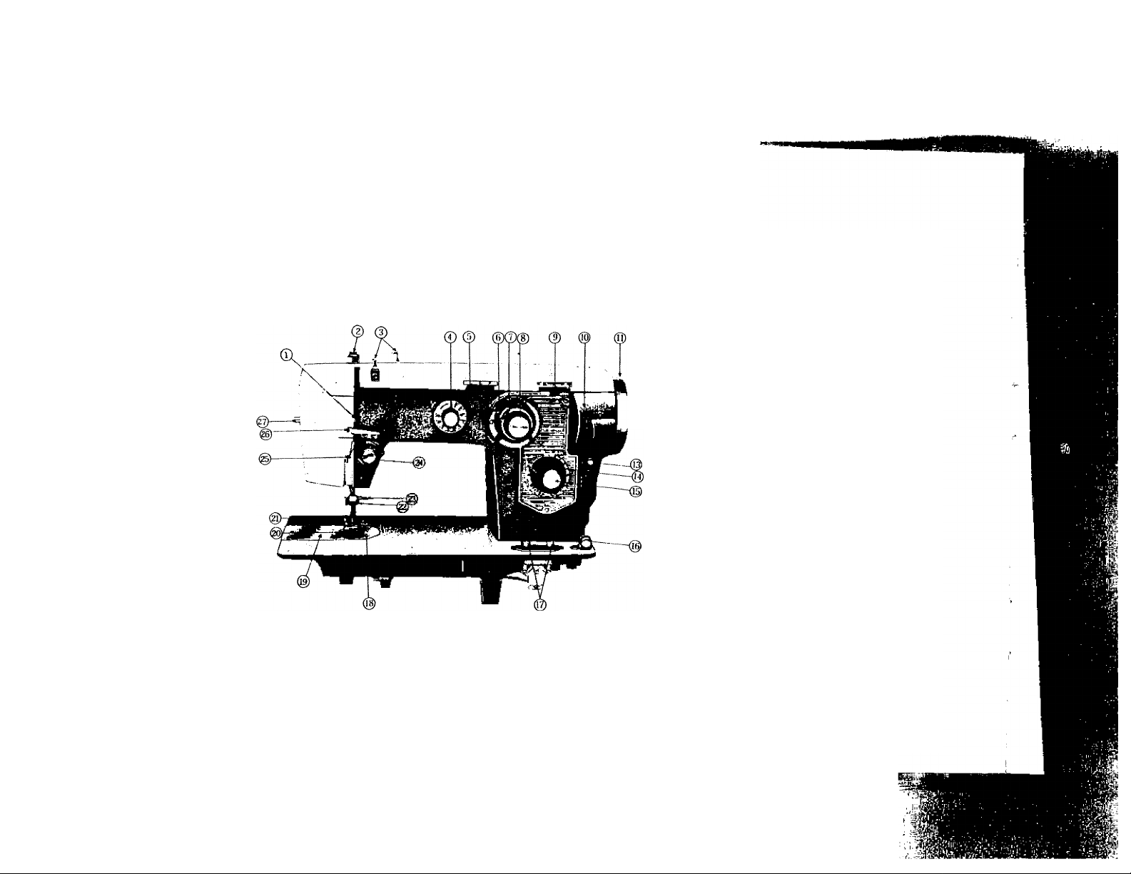
FEATURES AND PARTS
(Front View)
Fig. 1
1. Thread Take-up Lever
2. Pressure Release
(Darning)
3. Arm Thread Guides
4. Decorative Stitch Dial
5. Needle Position Lever
6. Buttonhole Control Knob
7. Zigzag Stitch Width Stop
8. Zigzag Width Control Knob
9. Pattern Selector Lever
10. Bobbin Winder Cover Door
11. Hand Wheel
12. Clutch
13. Cover Release Button
14. Stitch Length Control Knob
15. Push Button Reverse
16. Bobbin Winding Tension
17. Drop Feed Buttons
18. Needle Plate
19. Cover Plate
20. Presser Foot
21. Presser Foot Thumb Screw
22. Thread Cutter
23. Needle Clamp
24. Tension
25. Thread Guide
26. Thread Bar and Face Latch
27. Sew Lite Switch
■ K-
:
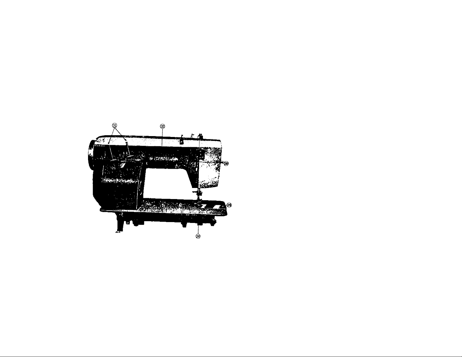
Fig. 2
Features and parts
(Back View)
28. Presser Bar Lifter
29. Feed
30. Head Hinge Mounting
Holes
31. Spool Pins
32. Handle
■
- ' I
V::

NEEDLE - THREAD - FABRIC - STITCHING GUIDE
■, ^ Vj-
Fabric
Extremely heavy
tarpaulin, sacking,
canvas, duck, etc.
Heavy upholstery
fabric, ticking,
denim, leatherette
Medium heavy drapery
fabric, velveteen.
suiting, felt, terry, etc.
Medium broadcloth,
percale, gingham, linen.
chintz, taffeta, sheer
wool, shantung, etc.
Sheer voile, lawn.
dimity, crepe.
handkerchief linen,
plastic film, etc.
Very sheer chiffon.
batiste, lace, organdy.
ninon, net, marquisett etc.
Needle
No.
4
3
2
1
0
00
Machine
Stitches
Per Inch
6
to
8
8
10
10
to
12
12
to
14
14
to
16
(Plastic film)
8 to 10
16
to
20
Cotton
Thread
10
30
3D
to
40
4D
to
60
60
to
80
80
to
100
100^
io
150
Mercerized
Thread
1
Fia.
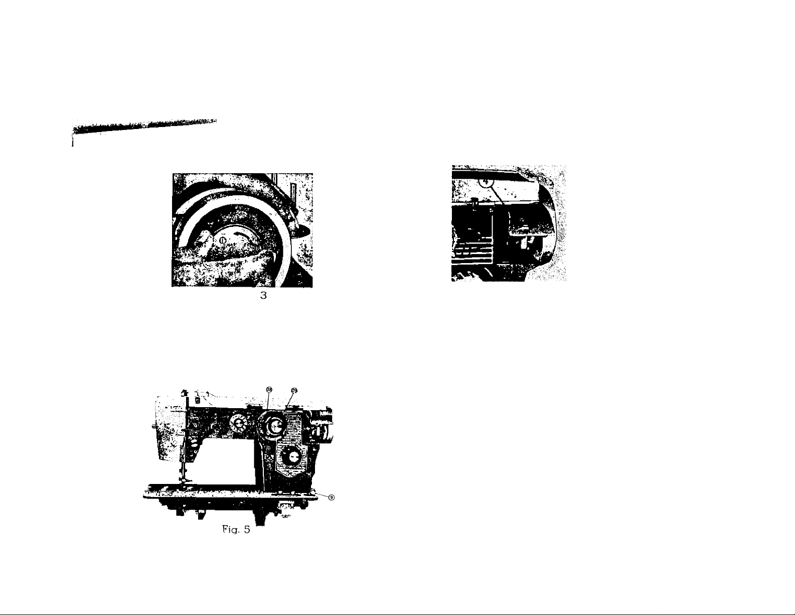
Fig. 4
WINDING THE BOBBIN
Disengage hand wheel (5, Fig. 3), from the stitching mechanism by turning clutch (6, Fig. 3)
toward you or counter clockwise.
Push latch (4, Fig. 4) to spring open cover (3, Fig. 4) of the recessed winder.
Place a spool of thread on one of the spool pins. Lead thread through the upper thread
guioe on arm and down through tension disc (9, Fig. 5,) at base of machine. Run end of thread
through a hole in bobbin edge (left flange
and from inside out) and place bobbin
on spindle of bobbin winder (7, Fig.4j fitting
the notch bobbin over small pin on spin
dle. Push bobbin winder against hand
---
(7)
wheel. Hold thread end loosely and start
machine slowly.
Bobbin will stop winding when it is
filled. Turn clutch away from you until
sewing mechanism is again engaged so
that needle moves when you turn the hand
wheel.
Break off loose thread end used to
start the winding and thread bobbin as
stated on Page 6
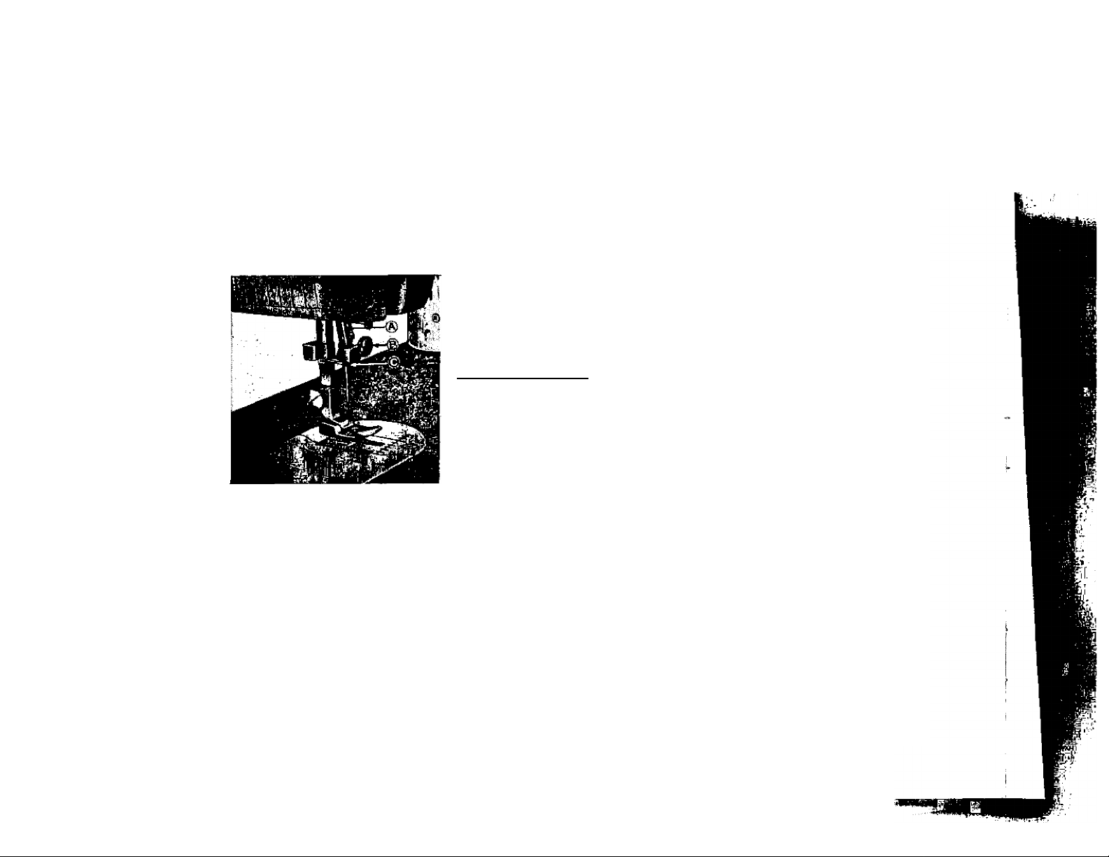
SETTING THE NEEDLE
See Fig. 6. Raise the needle bar A to its highest
point, turning wheel toward you by hand.
Then loosen the needle clamp screw B and the
needle can be inserted into clamp C. Place needle
(flat side to right) in the needle clamp and push it
upward as far as it will go into the needle clamp
hole, tightening the needle clamp screv/ securely
with a screw driver.
After changing the needle make one com
plete revolution of the balance wheel by
hand to be sure the needle is in the correct
position.
Fig. 6
Flat surface
oi needle
shank
/
Fig. 7
THREADING THE BOBBIN CASE
Step 1 (illustrated in Fig. 8). Hold bobbin case between thumb and forefinger of left hand,
so that the slot in the edge of the bobbin case is on top. Take the bobbin between thumb and
forefinger of right hand so that the thread on top leads from left to right.
Step 2. Insert bobbin into bobbin case, pull the thread into the slot of the bobbin case as
shown in Fig. 9, and draw it under tension spring and into the fork-shaped opening of the spring
as shown in Fig. 10.
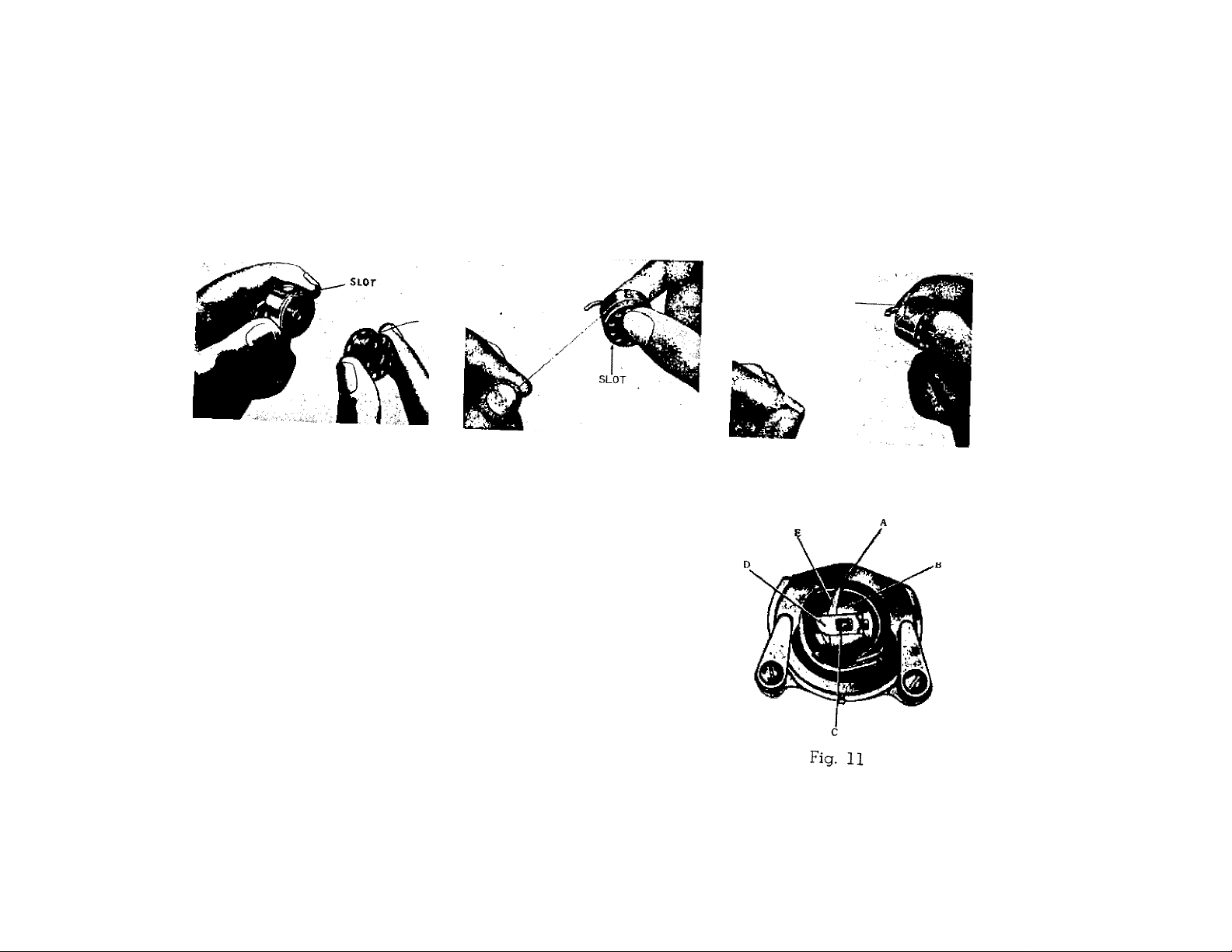
TENSION SPRING
Fig. 8
Fig. 9
PLACING BOBBIN CASE IN SHUTTLE
Raise needle bar to highest position, and slide cover nlate
L n K fbobbin case iXh S
whh at 1 rr"" ® forefinger of the left hand
tT K running from the top of
the bobbin case to the right. Insert and center the bobbin
case on the stud of the shuttle body, (C) Be sure the
PrisifteT hK "■ ‘he shuttle race notch (A)
Press the bobbin case (B) into the shuttle as far as oossible
rdLsi th *be shuttle. THEN
release the bobbin case latch, (D). Press bobbin case aaain
after latch has been released to make sure the bobbin case
IS locked securely in place. Close the cover plate
Fig. 10
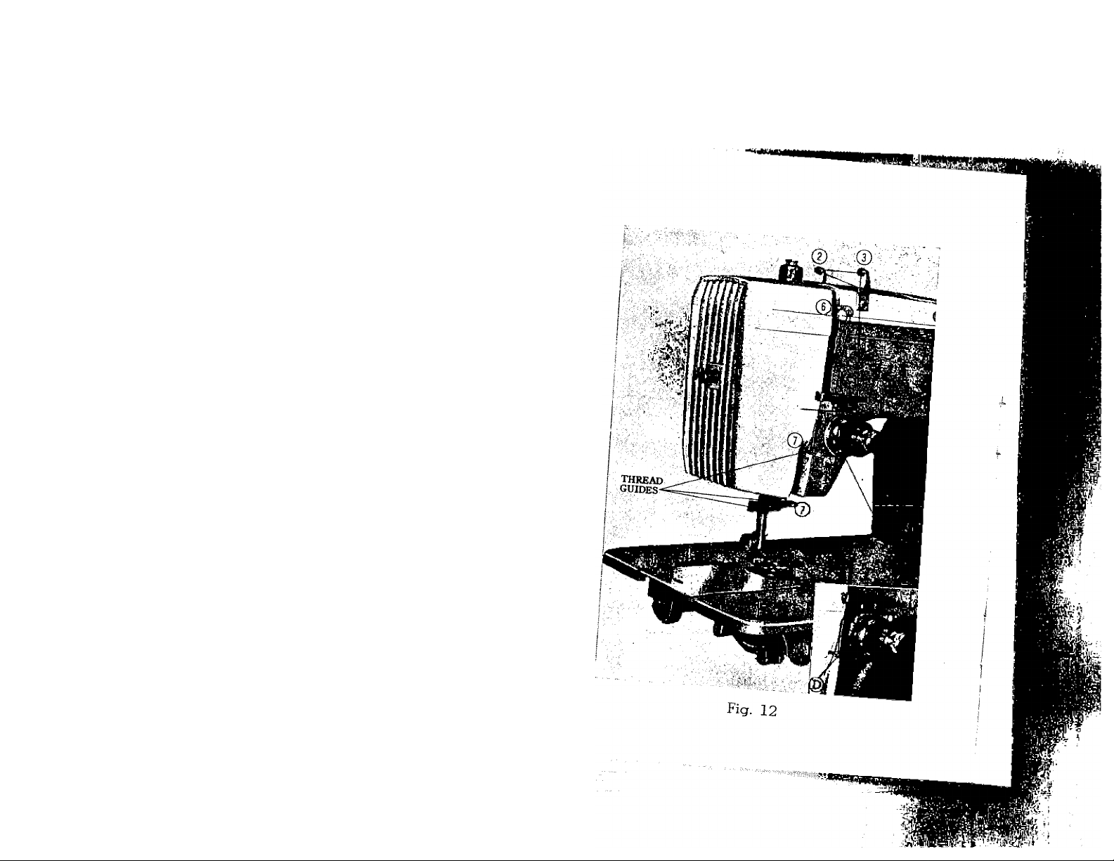
UPPER THREADING
the take^up^IevS
2.
Place a spool oTfh J ^
3.
head the thread through th”
guides. ™® upper arm thread
4.
5.
and with a slight tag^™o*'th'’'’h‘''’"”3
insert, Fig. 12) ^ 11^® hook, (Se©
6.
ftihyi S™t“S£Ji3,^;andup through
left. up lever from right to
face Plate®quidlslnd™ln'’ti'‘'’' the
bar guide from the bacP "®®ble
8.
drawing it through about f © «^GHT,
nold the pnH mf +k d or 4 inohoo
turn the hand wheM toS'’ ^°°s®ly and
goes all the way dowTand^:! "®®dle
A loop (Fig. 1^) ™ comes back up.
upper thread which thin c °ver the
straight. Place both th " out
slot of the presser fool^r^ ¿«ds under the
back of the machine, leati^ T,
three or four inches lonj ^
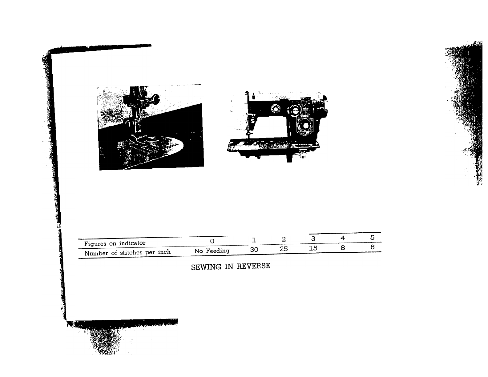
Fig. 13
Fig. 14
SETTING THE STITCH LENGTH
The length ol the stitch is ^
v“Sy“o1 toSths," 'iTn the d'ial to the r.glt to lengthen and to the left to shoxten the stitch.
The number stitch length you choose is indicated by the pointer.
STITCH LENGTH CHART (APPROXIMATE)
xn th^h“ .rH™lt‘iras’’S?'aTi? Srtctli^ setLch-.i°‘ai tonTii-S^
button is held in.
liPiPffim
HMIMI
10
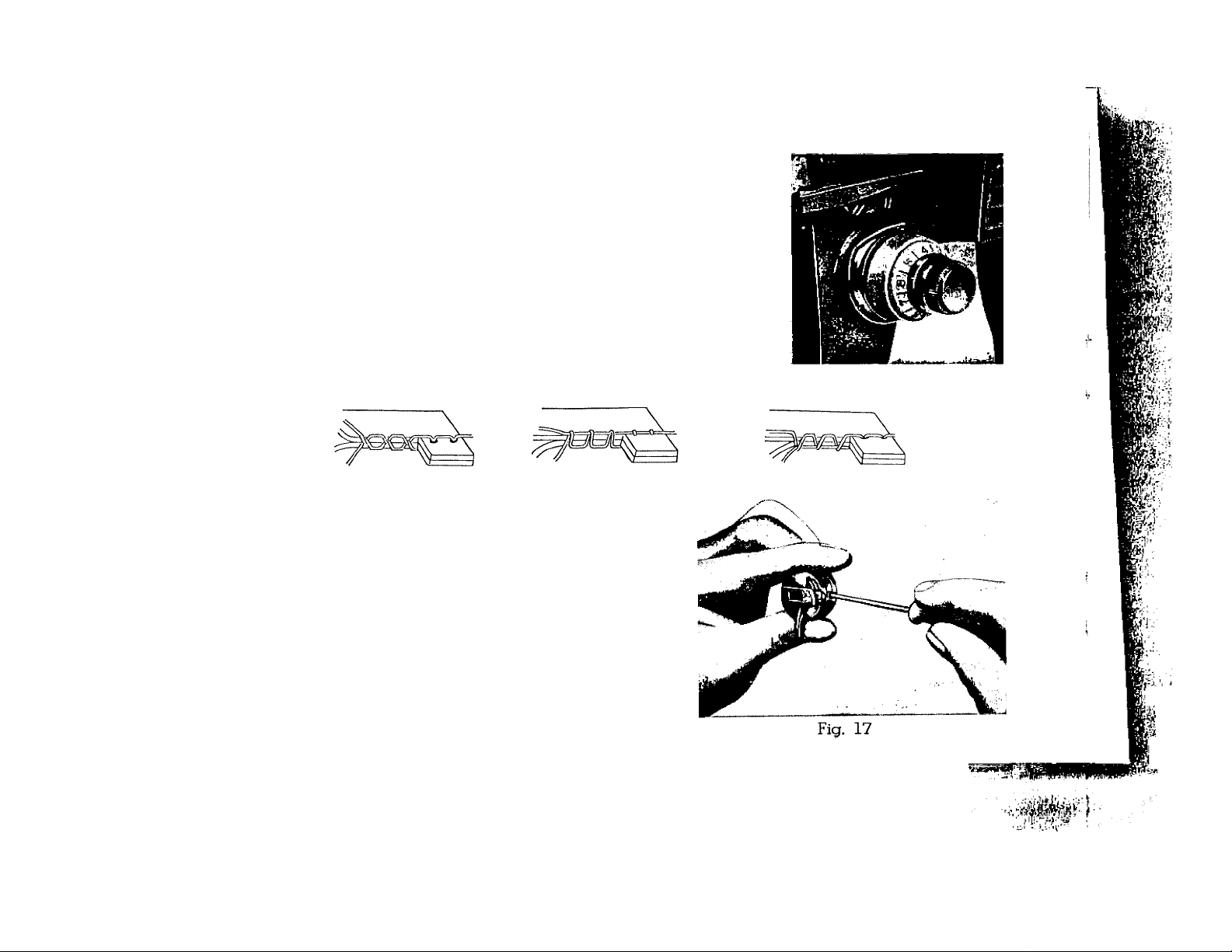
ADJUSTING THE TENSIONS
Always adjust the upper tension with the presser foot down,
as the tension is released when it is raised. To increase the
tension on the upper thread, turn dial (Fig. 15) to the right, or
clockwise; to decrease, turn to the left. The higher the number
on the dial the tighter the tension. Before adjusting lower tension
be sure that the machine is threaded properly.
When it is necessary to change the bobbin tension, turn
the small screw (Fig. 17) on side of the bobbin case clockwise to
tighten, counterclockwise to loosen.
Fig. 15
Fig. 16A Fig. 16B
When the upper and under tensions are properly
balanced, a perfect stitch will be formed with both
threads interlocking in fabric (Fig. 16-A).
When the upper tension is too tight, the lower
thread is pulled up over the upper thread which is
lying flat on the fabric (Fig. 16-B).
When the upper tension is too loose, the upper
thread forms loops over the lower thread lying flat
on the fabric (Fig. 16-C).
Fig. 16C
:
Ifebi'

M
11
sewing thin or light weight T’' '*°'“' ‘ “ ®‘’“‘■ "“'•
_ R,E.„ p„3.„„
flimsy material the satisfactnr ?
Release all fL ^ P^'^^sure cap should ^ «« thin
20) aud then pres3 Jo tl s ^^^fway
the feed slightly ^ ® ^^^in to half-wav^ p^g
^ed line. ^ pressing the DOWN button (Fio° 7
^ to the
darning and mending
In order to move the f u •
.t'pir
, pressure cap fi cnmr,i release
on the sn!p loewt'l>^ P-asing
down button (Z It Z i^- P-oas
Fig. 19
^h;ch drops the feed^ejJ If®
plate. To return feed to "^^dle
UP button all the way dLn
Fig. 20
12
PREPARING TO SEW
Have take-up lever at highest point before starting to sew. Do not try to help the feeding
by pulling the material as this may deflect the needle and cause it to break.
NEVER run machine without material under presser foot.
Place material and threads in position under the presser foot and lower the presser foot. You
are now ready to begin sewing. By having the needle at its highest point, it is not necessary
to touch the hand wheel to start the machine. You merely press the control. The speed of the
machine is regulated by increasing or decreasing the amount of pressure exerted on the control.
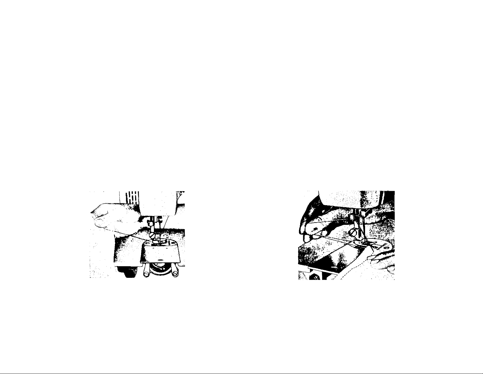
REMOVING THE WORK
Be sure to stop the machine
when the thread take-up lever
and needle bar are at the highest
position.
Now raise the presser foot
and draw the fabric back and to
the left (Fig. 21, A and B) and pass
the threads over the thread cutter.
Pull down slightly, holding
thread in both hands, so as not
to bend the needle.
Fig. 21A
Leave the ends of thread un
der the presser foot.
Fig. 21B
t"'-
P-
f:
r--'
 Loading...