

Page 1

SINGER
145W103,W203,W303
Page 2
2848w
INSTRUCTIONS
FOR USING AND ADJUSTING
SINGER SEWING MACHINES
Machine 145w303
145wl03, 145w203
and 145w303
THE SINGER MANUFACTURING CO.
Page 3

To all whom it may cortcern:
The placing or renewal of the name “Singer” (Reg. U. S.
Pat. Off.) or any of the trade marks of The Singer Manu
facturing Company on any machine that has been repaired,
rebuilt, reconditioned, or altered in any way whatsoever
outside a Singer factory or an authorized Singer agency
is forbidden.
THE IMPORTANCE OF USING
GENUINE SINGER PARTS AND NEEDLES
IN SINGER MACHINES
The successful operation of Singer machines can only be
assured if genuine Singer parts and needles are used. Sup
plies are available at all Singer Shops for the Manufacturing
Trade and mail orders will receive prompt attention.
Genuine Singer Needles should be used
These Needles and their Containers
Company’s Trade Mark “SIMANCO.” 1
in Singer Machines.
are marked with the
Needles in Containers marked
“For Singer Machines”
are not Singer made needles.
DESCRIPTION
MACHINE 145W103 Is a two-needle lock stitch machine with compound
feed and hlgh-llft alternating pressers. It Is used for tents, awnings,
furniture upholstery, leather coats, automobile work, etc. It has a
high arm with a working space of 10 Inches at the right of the needle
bar. The machine Is furnished In gauges from 1/4 to 2-1/2 Inches.
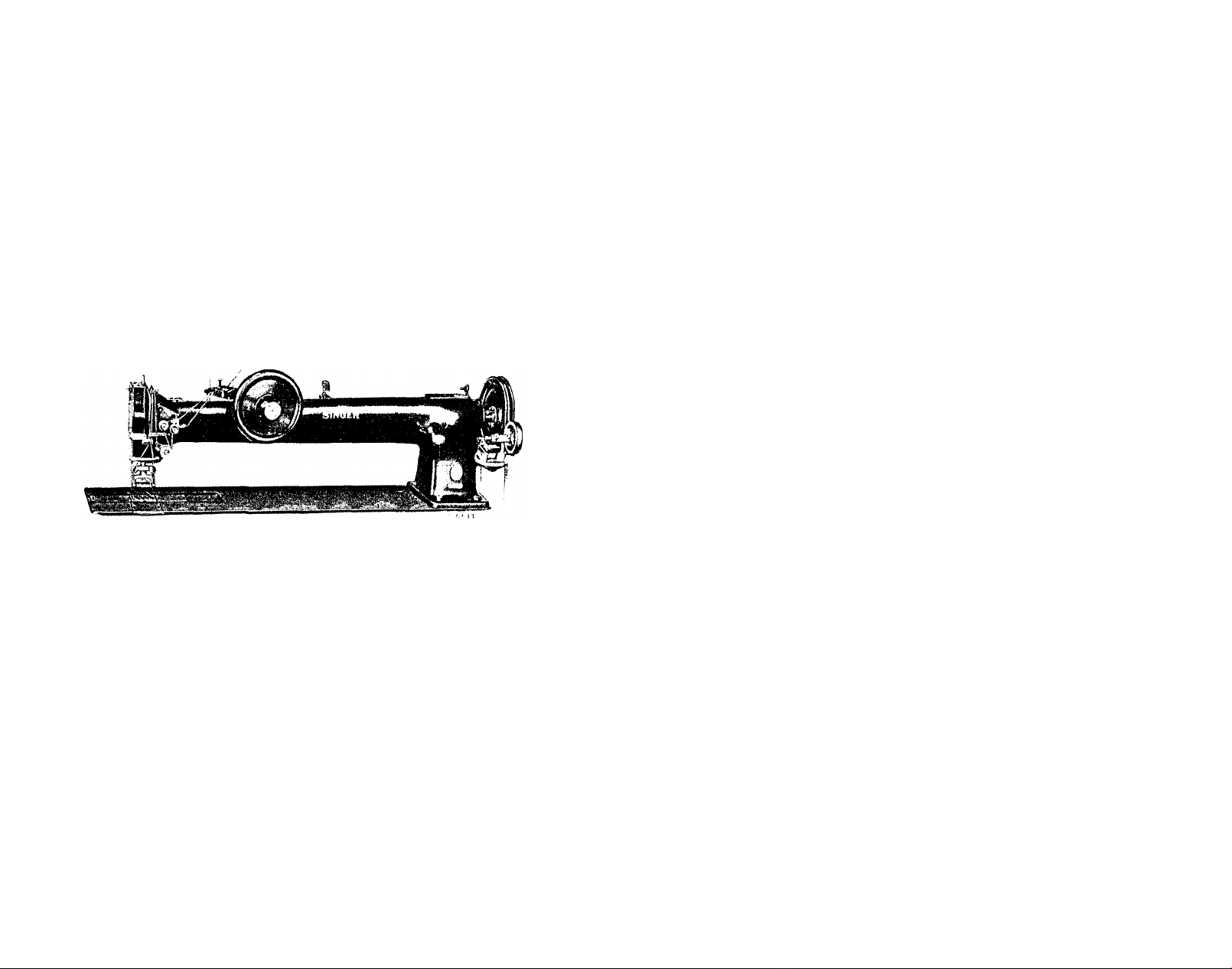
MACHINE 145W203 Is a long-arm machine with working space of 20
Inches at the right of the needle bar and is used for stitching
tarpaulins, tents, automobile door panels and for similar large work.
Otherwise the machine Is the same as Machine 145W103.
MACHINE 145W303 Is the same as Machine 145W203 except that It has
an extra long arm with a working space of 30 Inches at the right of
the needle bar. Has hand wheel at front of machine for convenience
of operator.
Speed
The maximum speed recommended for these machines Is ISOO revolu
tions per minute, when permitted by the nature of the material being
sewn. The machines should be run slower than the maximum speed until
the parts which are In movable contact have become glazed by their
action on each other. When the machines are In operation, the balance
wheel should turn over toward the operator.
Need Ies
Needles for Machines of Class 145w are of Class and Variety 7x23
for cloth, and 7x21 for stitching cardboard and fibre door panels.
They are made In sizes 22, 23, 24, 25 and 27.
The size of the needle to be used should be determined by the
size of the thread which must pass freely through the eye of the needle.
If rough or uneven thread Is used, or If It passes with difficulty
through the eye of the needle, the successful use of the machine will
be Interfered with.
Orders for needles must specify the quantity required, the size
number, also the class and variety numbers separated by the letter x.
The following Is an example of an Intelligible order:
"100 No. 24, 7x23 Needles."
The best results will be obtained when using the needles furnished
by the Singer Sewing Machine Company.
Page 4
Oiling the Mach ine
When the machines are received from the factory, they should be
thoroughly cleaned and oiled,
be oiled at least twice a day.
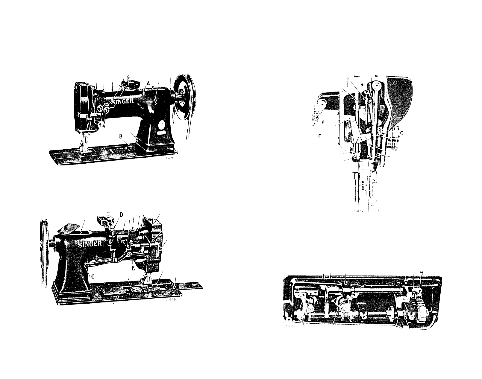
Fig. 2. Front View of Machine 145W103
Showing Oiling Points
Oil should be applied at each of the places designated by arrows
In Figs. 2, 3, 4, 5 and 25.
When In continuous use, they should
Loosen the thumb screw In the upper end of the face plate, turn
the face plate upward and oil the wick and bearings which are thus
uncovered, then turn dcwn the face plate and tighten the thumb screw.
Fig. 3. Rear View of Machine
Showing Oiling Points and Adjustments
Fig. 4. End View of Machine Showing Oiling Points
Also Adjustments on the Machine
Apply a few drops of oil four times dally to the felt pad In the
side wall of each bobbin case as Illustrated In Fig. 10.
J K
Fig. 5. Base of Machine Showing Oiling Points and Adjustments
Page 5

Th read
Use left twist thread for the needles,
twist thread may be used for the bobbins.
Fig. 6. How to Determine the Twist
Hold the thread as shown above. Turn the thread over tcward you
between the thumb and forefinger of the right hand; If left twist,
the strands will wind tighter; If right twist, the strands will unwind.
Either left or right
To Set the Need Ies
Turn the balance wheel over tcward you until the needle bar moves
up to Its highest position; loosen the set screws In the needle holder
and put the needles up Into the holder as far as they will go, with
their long grooves facing each other and their eyes In line, then
tighten the set screws.
To Remove the Bobbins
Draw back the slide plates In the bed of the machine and turn the
balance wheel until the bobbin case openers (M,Flg.7) move clear of
the bobbins. With the forefinger or a screwdriver, raise the latches
(L) to a vertical position and lift out the bobbins.
L M
To Wind the Bobbins on Machines IU5wl03 and IU5w203
(See Fig. 8)
Fasten the bobbin winder to the table with Its driving pulley In
front of the machine belt, so that the pulley will drop away from the
belt when sufficient thread has been wound upon the bobbin.
Fig. 8. Winding the Bobbin
Place the bobbin on the bobbin winder spindle and push It on as
far as It will go, being sure that stud (C) enters a hole In the bobbin.
Pass the thread dcwn through the thread guide (1) In the tension
bracket, around the back and between the tension discs (2). Then wind
the end of the thread around the bobbin a few times, push the bobbin
winder pulley over against the machine belt and start the machine.
When sufficient thread has been wound upon the bobbin, the bobbin
winder will stop automatically.
If the thread does not wind evenly on the bobbin, loosen the
screw (A) In the tension bracket and move the bracket to the right or
left as may be required, then tighten the screw.
The amount of thread wound on the bobbin Is regulated by the
screw (B). To wind more thread on the bobbin, turn the screw (B)
Inwardly. To wind less thread on the bobbin, turn the screw outwardly.
Bobbins can be wound while the machine Is stitching.
Fig. 7. Removing the Bobbin
Page 6

8
To Wind the Bobbins on Machine IU5w303
(See Fig. 9)
Place the bobbin on the bobbin winder spindle and push It up
against the shoulder until It Is In line with the bobbin winder latch.
To Replace the Bobbins and
Thread the Bobbin Cases
Hold each bobbin between the thumb and forefinger with the thread
drawing on the bottan frori left to right as shown In Fig. 10 and place
Is». to
Fig. 10. Direction of Thread on Bobbin
it on the center stud of the bobbin case, then push down the latch
(L,Fig.11). Draw the thread Into the slot (1,Fig. 10), under the
tension spring and Into slot (2) as shown In Figs. 10 and 11, leaving
a loose end of thread about two Inches long above the slide. When
closing the slide plates, leave Just enough space for the threads to
pass through.
Fig. 9. Winding the Bobbin
Pass the thread from the imwlnder, under and between the tension
discs (1), through the eyelet (2), and wind the end of the thread
around the bobbin (3) a few times. Push the bobbin winder pulley
against the balance wheel and press the latch against the bobbin. When
sufficient thread has been wound on the bobbin, the bobbin winder will
stop automatically. Bobbins can be wound while the machine Is
stitching.
Fig. 11. Bobbin Cases Threaded
Page 7

10
Threading the Needles
(See Fig. 12)
TO THREAD THE LEFT-HAND NEEDLE, pass the thread from the unwinder
through one of the holes (l) In the thread oiler, and under the wire
Z I
11
thread guide, over between the right tension discs (7R), down around
the front thread controller disc (8R) Into the thread guide (9) and
the take-up spring (10), up through guide (11), through the take-up
lever eyelet (12R), down through guide (13), Into the right thread
guide (MR) (used only for thread smaller than No. 12), back of lower
guide (15), Into right needle holder eyelet (16R), and from left to
right through the eye (17R) of the right needle.
To Raise or Lower the Presser Feet
The presser feet are raised by pressure on the foot treadle and
may be locked In the raised position by moving the lever (A,Fig.2)
all the way to the left. A slight pressure on the treadle will
autonatlcally release the locking device.
To Prepare for Sewing
with the left hand hold the ends of the needle threads, leaving
them slack from the hand to the needle. Turn the balance wheel over
I7L
17R
Fig. 12.
guide (2) (which may be raised by prying the end (x) out of Its posltlm
hole with a screwdriver and turning It to the right), then under the
oil pad (3) and out through one of the notches (4) In the thread oiler;
upward through eyelet (5L) and downward through eyelet (6L) In the
left thread guide, over between the left tension discs (7L), down
around the rear thread controller disc (8L) and Into the tlread con
troller thread guide (9), Into the tliread take-up spring (lo), up
through the guide (11), from right to left through the eye (12L) In the
take-up lever, down through the guide (13), Into the left thread guide
(14L) (used only for thread smaller than No. 12), back of the lower
guide (15), Into the left needle holder eyelet (16L) and from right to
left through the eye (17L) of the left needle.
TO THREAD THE RIGHT-HAND NEEDLE, pass the thread from the unwinder
through the thread oiler the same as for the left thread, then upward
through eyelet (5R) and downward through eyelet (6R) In the right
Fig. 13. Pulling Up the Bobbin Thread
tcward you until the needles move dcwn and up again to their highest
point, thus catching the bobbin threads; draw up the needle threads
and the bobbin threads will cone up with them through the holes In the
feed dog. Lay the threads back under the presser feet and close the
slides.
To Commence Sewing
Place the material beneath the presser feet, lower the presser
feet and commence to sew, turning the balance wheel over toward you.
Page 8

12
To Remove the Work
Have the thread take-up lever at the highest point, raise the
presser feet, draw the work back and cut the threads close to the
goods. Lay the ends of the threads back under the presser feet.
Tens i ons
The needle and bobbin threads should be locked In the center of
the thickness of the material, thus:
Fig. 14. Perfect Stitch
If the tension on the needle threads Is too tight, or If that on
the bobbin tlireads Is too loose, the needle threads will lie straight
along the upper surface of the material, thus;
Fig, 15. Tight Needle Thread Tension
13
To Regulate the Length of Stitch
The length of stitch Is regulated by the feed eccentric (B, Fig, 17)
located on the arm shaft.
If the tension on the bobbin threads Is too tight, or If that on
the needle threads Is too loose, the bobbin threads will lie straight
along the under side of the material, thus:
Fig. 16. Loose Needle Thread Tension
To Regulate the Tensions
The tension on the needle threads Is regulated by the two thumb
nuts (N, Fig. 18) at the front of the tension discs cn the front of the
machine. To Increase the tension, turn these thumb nuts over to the
right. To decrease the tenslai, turn the thumb nuts over to the left.
The tension on the bobbin threads Is regulated by means of the
screw nearest the center of the tension spring on the outside of each
bobbin case. To Increase the tension, turn this screw over to the
right. To decrease the tension, turn this screw over to the left.
Fig, 17. Feed Eccentric. Arm Cap Removed.
To lengthen the stitch, loosen screw (C,Fig.17) turn the feed
regulating screw (A,Fig.17) over toward the left. To shorten the
stitch, turn this screw (A,Fig. 17) toward the right. When the desired
length of stitch Is obtained, securely tighten screw (C).
To Regulate the Pressure on Material
To Increase the pressure of the presser feet on the material, turn
the thumb screw (D, Flg.3), at the back of the machine, downward. To
decrease the pressure, turn this thumb screw upward.
The pressure on the material should only be sufficient to enable
the feed to move the work along evenly.
Page 9

15
INSTRUCTIONS
FOR
ADJUSTERS AND MACHINISTS
Thread Controller
The thread controller spring should be set so that It reaches Its
lowest point as the eyes of the needles nearly reach the goods In
their descent.
Fig. 18. Aljustment of Thread Controller
For more controller action on the thread, loosen the stop screw
(P, Fig. 18) at the right of the controller and set the stop Icwer, and
for less action set the stop higher.
To strengthen the action of the controller spring on the thread,
loosen the spring stud screw (Q, Fig. 18) at the rear of the stop screw
and turn the spring stud (0, Fig. 18) slightly to the left with a screw
driver, or to lighten Its action turn to the right and retlghten the
spring stud screw.
Page 10

16
To Set the Needle Bar
See that the needles are up In the holder as far as they will go.
There are two lines across the needle bar about two inches above the
Icwer end. When the needle bar is at Its lowest position, the upper
mark should be Just visible at the end of the needle bar frame.
In case the needle bar Is not correctly set, loosen the needle bar
connecting stud pinch screws (G, Flg,4) and place the needle bar in
correct position as directed above, then retlghten the screws (G).
To Set a Needle Bar Which Has No Mark
Adjust the feed eccentric (B, Fig.17) so that there Is no feed
movement of the needle bar frame, then set the needle bar so that when
It rises 1/8 Inch from Its lowest position, the points of the sewing
hooks will be about l/ie Inch above the eyes of the needles.
17
To Change the Amount of Lift of
the Alternating Pressers
The height of lift of the pressers Is adjustable by moving the
link (F, Flg.4) to any of the four holes In the rock shaft crank. The
majclmum lift Is secured with the link In the bottom hole. The amount
of lift should be regulated according to the thickness of the material
being sewn. The feet should lift Just high enough to clear the
material.
To Adjust the Relative Height of Lift of the Vibrating and Lifting Pressers
As a rule, the vibrating and lifting pressers should lift an equal
height, but some grades of work may require that they lift an unequal
height. To change the relative lift of the presser feet, loosen the
screw (E,Flg.3) at the back of the machine and move the vibrating
presser bar upward or downward as required, then securely tighten
the screw (E).
Relative Positions of Vibrating Presser Bar
and Lifting Presser Bar
The distance between the vibrating presser bar and lifting presser
bar, after adjusting the feed eccentric (B, Fig. 17) so that there is no
feed movement of the needle bar, should be 5/8 Inch as shown In Fig. 4.
If the distance between the vibrating presser bar and the lifting
presser bar Is more or less, Insert a screwdriver In the hole at
(C,Flg.3) at the rear of the machine and loosen the clamp screw which
holds the needle bar rock frame rock shaft. While this screw Is loose,
the needle bar frame can be moved forward or backward to the required
distance. A piece of metal of the correct width may be used to deter
mine the correct distance. When making this adjustment be sure to see
that the feed eccentric (B,Fig. 17) Is set so that there Is no feeding
movement of the needle bar. When the adjustment has been made, securely
tighten the clamp screw at C.
,' i.'
To Time the Sewing Hook
Adjust the feed eccentric (B,Fig. 17) so that there Is no feeding
motion.
Remove the throat plate and turn the balance wheel over toward
you until the lower mark across the needle bar Is Just visible at the
end of the needle bar
If the needle bar and sewing hooks are correctly timed, the points of
the hooks will be at the centers of the needles and about 1/16 Inch
above the eyes.
In case the sewing hooks are not correctly timed, turn the balance
wheel over toward you until the needle bar has descended to Its lowest
point and has risen until the Icwer timing mark across the needle bar
Is Just visible at the end of the needle bar frame.
Loosen the two screws In the hub of each hook driving gear (T, Fig.
I
19) and tap this gear to the right or left on the hook driving shaft
until the point of the hook Is at the center of the needle. Tapping to
the right gives an earlier hook timing, and to the left a later hook
timing. Securely tighten the two set screws In each gear (T).
frame on the upward stroke of the needle bar.
Page 11

18
To Set the Sewing Hooks To or From the Needles
To prevent the points of the hooks from dividing the strands of
the thread, they should run as close to the needles (within the scarf)
as possible.
R S T U S T R >
Fig, 19. Adjustment of Hook Saddles
Turn the balance wheel over toward you until the points of the
sewing hooks are at the centers of the needles. Loosen the four screws
(R, Fig. 19) underneath the bed of the machine and move the hook saddles
to the right or left, as may be required, until the points of the hooks
are as close to the needles as possible without striking them, then
securely tighten the four screws (R).
The needle guard (Y,Fig.21), which Is attached to the side of each
sewing hook, should be sprung until It prevents the needle from striking
the hook In case the needle is deflected towards the hook.
Fig, 20. Removing Bobbin Cases
19
To Remove the Bobbin Cases from the Sewing Hooks
Remove the bobbin case openers (M, Fig. 20); remove the four hook
gib screws (W,Fig. 20) from each sewing hook, lift off the hook gibs
(Z, Fig. 21) and remove the bobbin cases (X, Fig. 20).
To Remove the Sewing Hooks from the Machine
Remove the throat plate, feed dog and the bobbin case openers.
Loosen the two screws In each hook shaft gear (S, Fig. 19) and lift out
the sewing hooks.
Fig. 21. Sewing Hook Removed from Machine
Shewing Hook Gib and Needle Guard
To Raise or Lower the Feed Dog
Usually when the feed dog Is at Its highest position. It should
show a full tooth above the throat plate.
Remove the throat plate; clean the lint and dust from between the
feed points and replace the throat plate; tip the machine back and
turn the balance wheel towards you until the feed dog Is at Its highest
position; loosen screw (U, Fig. 19) In the feed lifting cam fork on the
feed bar and raise or lower the feed dog, as may be required, and
re tighten the screw (U).
Vihen raising or lowering the feed dog, be careful that Its under
side does not drop low enough to strike the sewing hooks.
The feed dog should be set so that the needles are centered In
the needle holes. In case the needles do not enter the holes In the
feed dog correctly, loosen the pinch screw (H, Flg.5) and adjust the
feed dog as required, then securely tighten the pinch screw (H).
Page 12

20
To Remove the Needle Bar Rock Frame Rock Shaft
Remove the face plate and needle bar rock frame, then loosen the
clamp screw at (C,Fig.?) and draw out the rock shaft.
To Remove the Arm Shaft Connection Belt
from within the Arm
Slide the connection belt off the lower belt pulley; remove the
balance wheel; loosen the three screws In the arm shaft bushing near
the balance wheel and remove the bushing; lift the belt up through the
arm cap hole as far as possible and draw It out through the space
normally occupied by the bushing.
Owing to the fact that the sewing hooks make two revolutions to
one revolution of the hook driving shaft, and that the feed lifting
eccentric Is on the hook driving shaft. It Is possible to have the
sewing hooks correctly timed without having the feed correctly timed.
To overcane this, the plate (J,Flg.5) Is attached to the underside of
the bed of the machine. This plate Is marked with an arrow at Its
lower end and directly aloTigslde of the plate Is the collar (K, Flg.5)
mounted on the hook shaft, which Is also marked with an arrow. After
replacing the belt over the upper pulley, replace the arm shaft bushing
and securely fasten It In position by Its three screws; replace the
balance wheel. With the belt on the upper pulley, turn the balance
wheel fron you until the thread take-up lever Is at Its highest point.
Then turn the hook shaft with the fingers until the two arrows, one on
the plate (J) and the other on the collar (K), are directly In line.
New, without disturbing either the arm shaft or the hook shaft, slip
the belt over the lower pulley. The feed will then be correctly timed
with the needle bar.
21
To facilitate the replacing of the belt on the lower pulley, use
belt replacer 265068 (A, Fig. 22). Rest the replacer In the loop of the
the belt and slide It ov'er the hub of the pulley, as shewn In Fig. 22,
having the notches In the replacer engage the two set screws In the
hub of the pulley. Catch the belt clips In the groove at the lower
part of the pulley and turn the balance wheel toward you until the
belt Is fully over the pulley, assisting the belt clips from under the
pulley rhn with a screwdriver when necessary. Then remove the replacer.
NOTE: As belt replacer 265058 will serve for several machines
It Is not regularly furnished with the machine, and must be ordered
separately.
To Re-engage the Safety Clutch
The hook driving shaft and the shafts of the sewing hooks are
spllned to prevent the hooks from getting out of time. The safety
clutch located In the lower belt pulley prevents damage In the event
of any unusual strain on the sewing hooks by releasing the locking
lever In the pulley from the notch
hook driving shaft.
(Dl,Flg. 24) In the collar of the
Fig. 22. Putting Belt on Lewer Pulley with
Belt Replacer 265058
Fig. 23. Safety Clutch Disengaged Fig. 24. Operating Position
Draw back the bed slides, turn the balance wheel back and forth
slightly, and remove the material that may be Jamming the hooks. If
necessary to re-engage the clutch, press down the lock stud (B, Fig, 2)
^near the base of the arm to engage the hook driving shaft lock ratchet
(Al,Flg. 23) which will prevent the hook driving shaft from turning
backward. Turn the balance wheel away fron you until the locking lever
(Bl) snaps Into the notch (Dl) In the shaft collar as shewn In Fig. 24.
Release the lock stud and resume sewing.
Page 13

22
To Adjust the Hand-Wheel Shaft
on Machine IU&W303
The hand-wheel shaft bushing (FI,Fig.25) Is eccentric and may be
rotated to bring the hand-wheel gear (Gl,Flg.25) Into proper engagement
Fig. 25. Rear View, Showing Adjustments and Oiling Points
at Top of Lcng-Arm Machines
with the gear on the arm shaft. Loosen the bushing set screw (El, Fig.
25) and the bushing (Fl) may then be tapped around by means of a screw
driver In holes In Inner end of bushing until there Is only a trace of
bac)tlash between the gears. Then tighten the set screw (El).
Parts Required for Changing the Gauge of a Machine
The following Hook Saddle Bearings are used for different gauges:
Gauge
1/4 to 1-1/8
1-5/32 to 2-1/16
2-1/8 to 2-1/2
Hook Saddle Bearings
(Left)
265272
265274
223680
(Right)
265273
265275
223681
When changing the gauge frcm one of these ranges to another, a new
pair of hook saddle bearings must be ordered. In addition to these,
a new feed dog, throat plate, presser foot and needle holder will be
required for each gauge.
 Loading...