

Page 1

How lo use and care for your
SUPER ZIGZAG SEWING MACHINE
MODEL
1776
Page 2

INDEX
w
<1
h-l
Accessories-
How to Use
..................................................
............................................
Hemmers................................................26
Quilting Guide ..............................27
Seam Gauge or Cloth Guide
Attachments-
.................................................
Adjustadle Cord and Zipper Foot 41
Attachment Foot
...................................
Binder ....................................................38
Edgestitcher
Hemmers
..........................................
..........................................
Rüffler....................................................43
Blind Stitching-
..............................................
Bobbin
Placing in Shuttle
Threading
Winding
Buttonholes
.................................................
..................................................
Buttons Sew-On
...............................................
.................................
...........................................
Charts
Need-Thread-Fabric-Stitching
Stitch Length -----
............ • • •
................
39-40
.............
..........
Pages
24
25
27
35
36
36
20
7
6
5
17
22
4
.............
9..........
Pages
Trouble....................................... 31-32-33
Darning and Mending ..................................11
Decorative Stitches........................................19
Embroidery
Creative ................................................ 15
Hoop.......................................................16
Features and Parts (Front View)
(Back View)
Installation-Head in Cabinet
Head in Portable Case
Maintenance and Care -.
...............................
..................
...............
.......................
............
49
47
28
Cleaning and Oiling the Shuttle ---29
Needle Setting
Pressure and Feeding of Fabric
Thin and Light weight Fabrics
...............................................
................
...........
11
11
Reverse Sewing ............................................. 9
Selection of Stitch
Sewing Preparation
Sewing TipsStraight Stitching-
.........................................
.....................................
.............................................
.........................................
13
12
45-46
14
Stretch Stitching............................................23
Tension Adjustment .....................................10
Threading-Upper-........................................... 8
2
3
6
Page 3
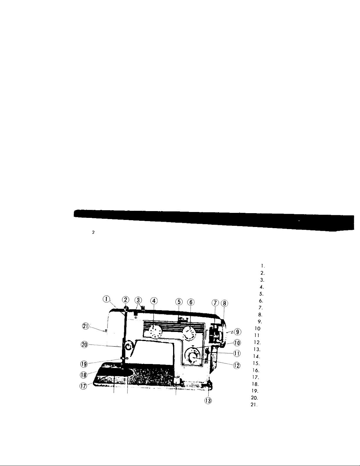
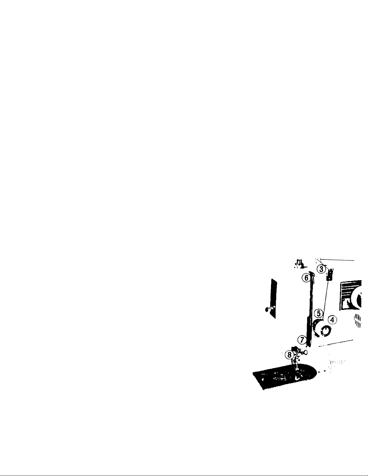
features and parts
(Front View)
® n,., 0
Thread Take-up Lever
Pressure Release
Arm Top Thread Guides
Decorative Stitch Selector Dail
Zigzag Creative Embroidery Le'
Z.gzag Width & Buttonhole Con
Dobbin Winder
Hand Wheel
Clutch Nut
■ Stitch Length Control
• Stretch Stitch Control
Push Button Reverse
Bobbin Winder Tension Disc
Drop Feed Control
Needle Plate
Slide Cover Plate
Presser Foot
Presser Foot Clamp Screw
Needle Clamp
Tension Regulator
Sew Light Switch
Page 4
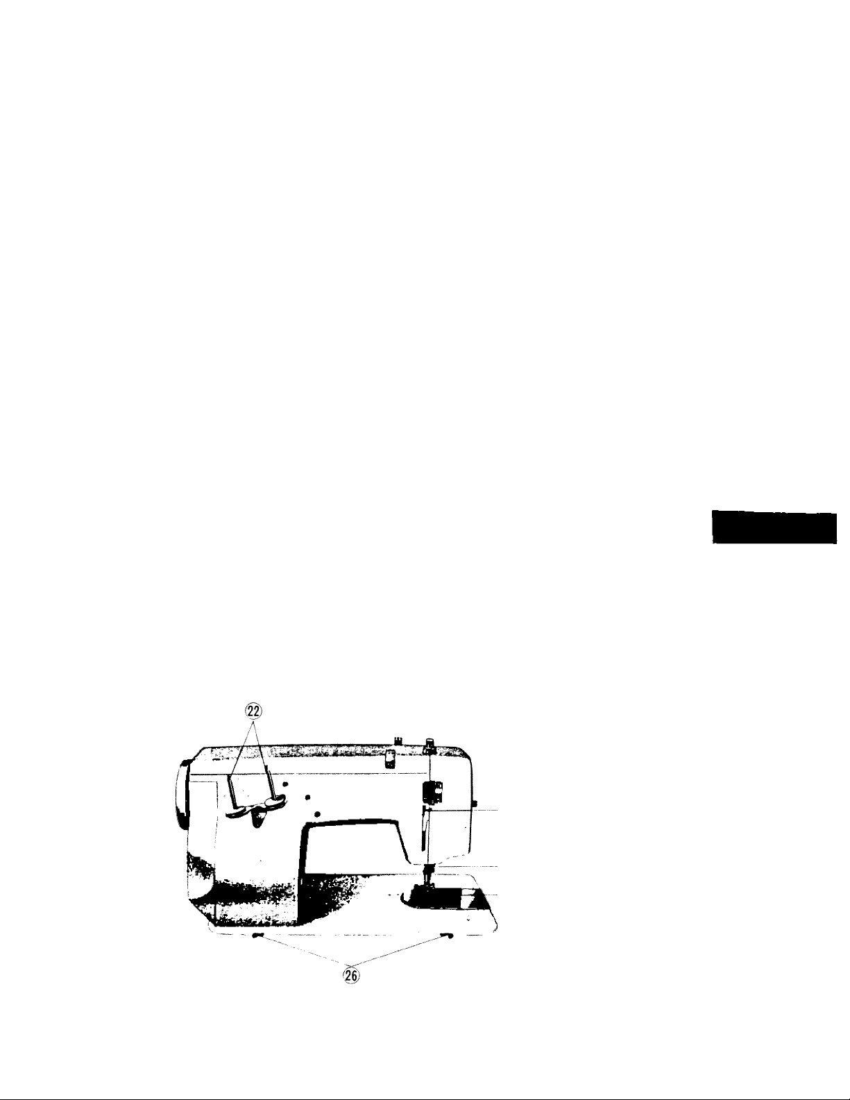
FEATURES AND PARTS
(Back View)
Fig . 2
22. Spool Pins
23. Presser Bar Lifter
24. Thread Cutter
25. Feed Dog
26. Head Hinge Mounting Holes
'-Cm
Page 5

needle-thread-fabric-stitching
guide
Fabric
Exfremely heavy
tarpaulin, sacking,
—etc.
Heavy upholstery
fabric, ticking,
denim, leatherette.
Medium heavy iopei^
fabric, velveteen
_;a'ting, felt, ferry, etc.
Medium broadcloth
percale, gingham, linen
chmtz, taffeta, sheer ’
'^ool, shantung, etc.
Sheer voile, lawn,
dimitv, crepe,
handkerchief linen.
Plastic film, etc.
Very sheer chiffon
batiste, lace, organdy
-2Z on.net, marquise» ’ etc.
Needle
No.
18
16
14
n
Machine
Stitches
Per Inch
14
to
16
(plastic film)
8 to 10
Mercerized
Thread
Heavy Duty
Heovy Duty
Heavy Duty
50
50
Synthetic
Thread
o
o
Page 6

» I
■l.''
Fig. 3
Fig. 4
WINDING THE BOBBIN
D.sengoge the hand wheel (,. Fig 3) fron, the stitch,ng n,echan,sm by turning the clutch
KZ, Fig. 3) toward you or counter clockwise. uiurcn
amie?f3\T°F°' O through the arm top thread
9 es-(3.&4, F,g.5) and the bobbin winder tension disc at the right front of bedplate (5,Fig.5)
Run end of thread through a hole in the left
flange of bobbin from inside to outside and
3; , , place bobbin on spindle of bobbin winder
* fitting the notch on bobbin over
FiO- 5 the winding.
small pin on spindle. Press bobbin winder
latch (7, Fig. 4) down, and hold thread end
loosely then start machine slowly.
Bobbin will stop winder when it is filled.
Turn clutch away from you until sewing
mechanism is again engaged so that needle
moves when you turn the hand wheel.
Break off loose thread end used to stort
Page 7
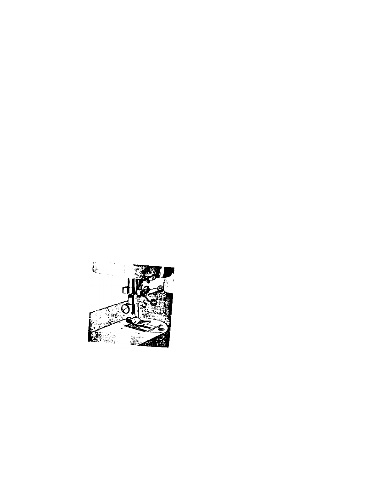
Fig. 6
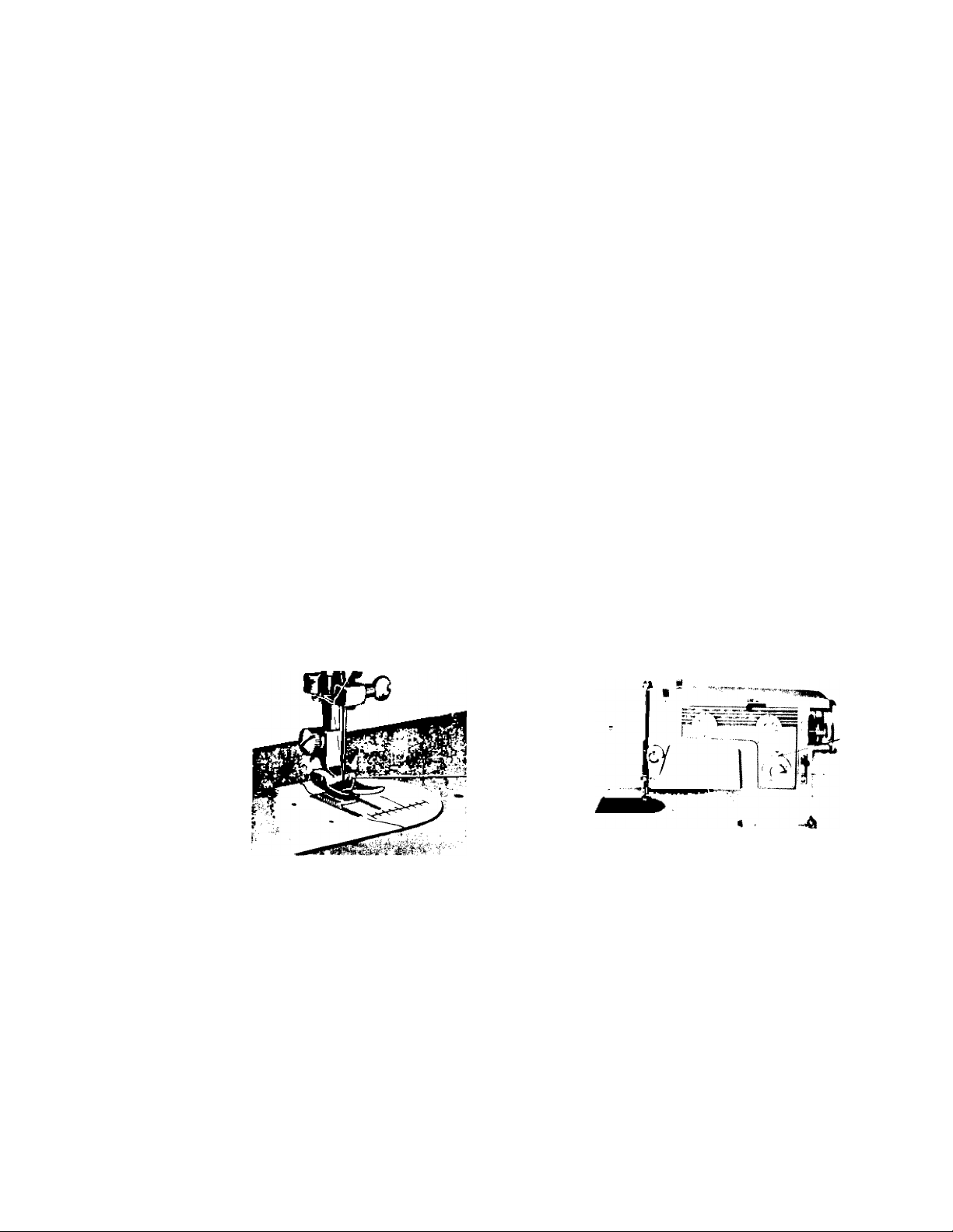
setting the needle
See Fig. 6. Ra.se (he needle a
„ ,J J, "••■il« =l™p ond P„.h ,
fiole, tightening the needle clarn'o ° ' * clamp
a screw driver. ^ screw securely with
After changing the neArti.» ,
píete revolution '»eke °"e com-
to be sure ,ho needle is 1^ ,e L ,
position. correct ^
surface
of needJe
shank
/
Step 1 (illustrated in Fia 8Í u u l ll ^A5>t
THREADING THE BOBBIN CASE
Page 8
SLOT
TF.NSION SPRING
SLOT
Fig. 8
Fig. 9
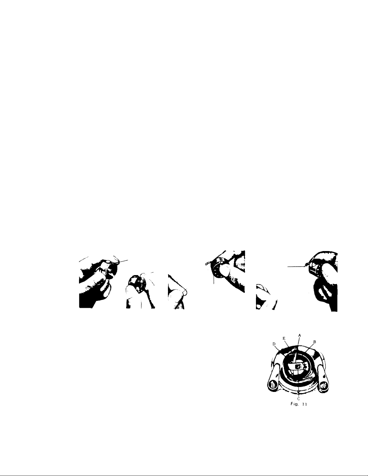
PLACING BOBBIN CASE IN SHUTTLE
Raise needle bar to highest position, and slide cover plate
to the left (l6, Fig, l). Hold the bobbin cose latch, (D,
Fig, 11) between the thumb and forefinger of the left hand,
with at least three inches of thread running from the top of
the bobbin cose to the right. Insert and center the bobbin
cose on the stud of the shuttle body, (C). Be sure the
bobbin case finger, (E), is opposite the shuttle race notch (A).
Press the bobbin case (B) into the shuttle as for as possible
until latch catches on the center post of the shuttle. Then
release the bobbin case latch, (D), Press bobbin case again
after latch has been released to make sure the bobbin case
is locked securely in place. Close the cover plate.
Fig . 1 0
Page 9
UPPER THREADING
1. r„rn ,k,
take-up lever to its highest position.
2. Ploce o spool of threod on the spool pin
4 hIw- ^ top threod guides
pull Z d 'Ti -‘»h 'he right hond.'
pull the end of threod between the tension discs
from right to left. ’
5. Pull the spring wire loop up until the threod
posses beyond the beok of hook to the righf
Aen pul the threod bock to the left, the threod
will be slipped into the hook ond the spring wire
loop will return to position. See Fig. I2-B
6. Up ond through the eye of the toke-up lever
from right to left.
7. Leod threod down through threod guide ot the
lower end of threod guide plate in the slot
the dl 'trough
fhe needle bor guide from the bock
thrl K drowing it
hrough obout 3 or 4 inches. Hold the end of
he upper thread loosely and turn the hand wheel
toward you until the needle goes all the way
S forced '°°P (Pig- '3) wii
be formed over the upper threod which then con
be pulled out straight. Place both threod ends
to dZ -d "ow
toward the back of the machine, leaving both
threods three or four inches long.
f^tg- 12
Fig. 12-B
Page 10
Fig, 13
SETTING THE STITCH LENGTH
The length of the stitch is regulated by the dial (lO, FiS-T^)- Near 0 is the shortest stitch
and 5 IS the longest, but the dial may be set at any spot between the markings for a variety
of lengths. Turn the dial to the left to lengthen and to the right to shorten the stitch. The
number stitch length you choose is indicated by the pointer.
STITCH LENGTH CHART (APPROXIMATE)
Fig. 14
Figures on indicator
Number of stitches per inch
0
No Feeding
30
1
25
2
15
3
4
8
SEWING IN REVERSE
when you wish to sew backward to tie the threads at the beginning or end of a seam, press
in the button (12, Fig. 14) as far as it will go. The machine will sew backward as long as the
button is held in.
Page 11
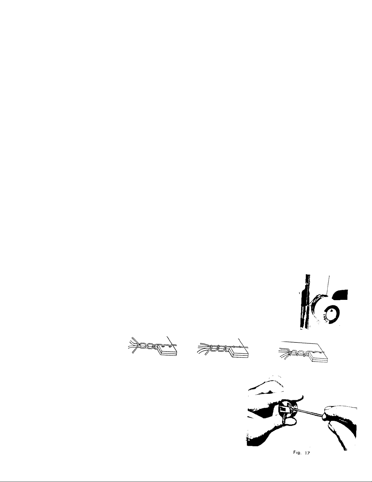
adjusting the tensions
’•> lension i. whir«
tension on the upper threod i L «ncreose
To decrease, turn to the left’ ^Before
be sure that the machine .k j j °d|usting lower tension
screw (Fig. 17) on side of'"theTobbin co°^^'"| stnoll
countencbclcwise to loosen dtxrkw.se to tighten,
Fig. 16-A
Fig. 16“B
When the upper tensions ore properly bol j
o perfect stitch will be formed whh bo,h th 7 ’
-nterlockmg in fabric (Fig. I6-A) . ^
-blil %TZ TefL" T'
'Vn. fbt on the fo^ric ;F;.^6T^
on the fabric (Fig. I6-C) flat
'ir :r::« r
n,
the
F»g. 15
Fig. 16-C
Page 12

ADJUSTING PRESSURE AND FEEDING OF FABRIC
General Sewing. Usually for normal sewing the pressure bar cap or darner release
(Fig. 19) is at its lowest position and the drop feed knob is turned to "HIGH” position(Fig. 18)
Sewing regular weight fabrics. When lighter pressure is required to sew satisfactorily on
bulky, heavy material, the pressure cap should be about halfway down. Release all
the way by pressing the snap lock (A, Fig. 20) , and then press cap(B) down again to
halfway spot. To sew thin, lightweight fabrics lower the feed slightly by turning the
knob to "low” position.
DARNING AND MENDING
In order to move the fabric freely in any
direction for darning and mending, release the
pressure cap (B) completely by pressing down
on the snap lock (A, Fig. 20) . Turn knob to
‘DOWN” position, which drops the feed well
below the needle plate. To the return feed to
Fig. 19
normal, return knob to "HIGH”position (Fig. 18)
Fig. 20
Fig. 18
Page 13
u , ■ ■•‘-'-««IIMU TO SEV
Have take-up lever c k- L v.
by pulling the material as th^^"' »o sew n
preparing to sew
S''»- -
r,;„:r zz'lrLr,^- *• p—
p.... c'.7: ztr *-i:
P™"“’-« •««. on th, „n„
removing the work
»7r:77,::.„77;:„.
:r* ”'•»' "S
left (Fig. 21, A and B) r,J
°7'- 'be thread Tuner
in 11 kZ '’““'"P "■ .Pd
Fig . 2 1- A
Leave the ends of thread under
the presser foot.
Fig . 2 1- B
Page 14
'ii)
Fig. 22
SELECTION OF STITCH
In addition to ordinary straight and zigzag stitches, five automatic garment-make stitches of blind
hem stitching, straight and Rick-Rack stretch stitches, overcast stretch hem stitches, also, eight kinds
of automatic decorative stitches are availadle with setting the pattern selector dial at your desired
stitch position.
For ordinary straight and zigzag stitches, set the selector dial (4. Fig. 22) at M with stretch stitch
control (1 1, Fig. 22) at M.
For straight and R.ck-Rock stretch stitches, set the selector dial at M with the stretch control at S.
For bind hem stitching set the selector dial at with the stretch control at M, end for
rcos stretch hem stitch, some selector dial position, but with the stretch control at S, be applied.
For other automatic decorative stitches, be the pattern selector dial at the position of symbolized
make of decorative stitch pattern you desire.
For further detail, please refer to each relative, page for every different kind of stitch.
13
Page 15
STRAIGHT STITCHING
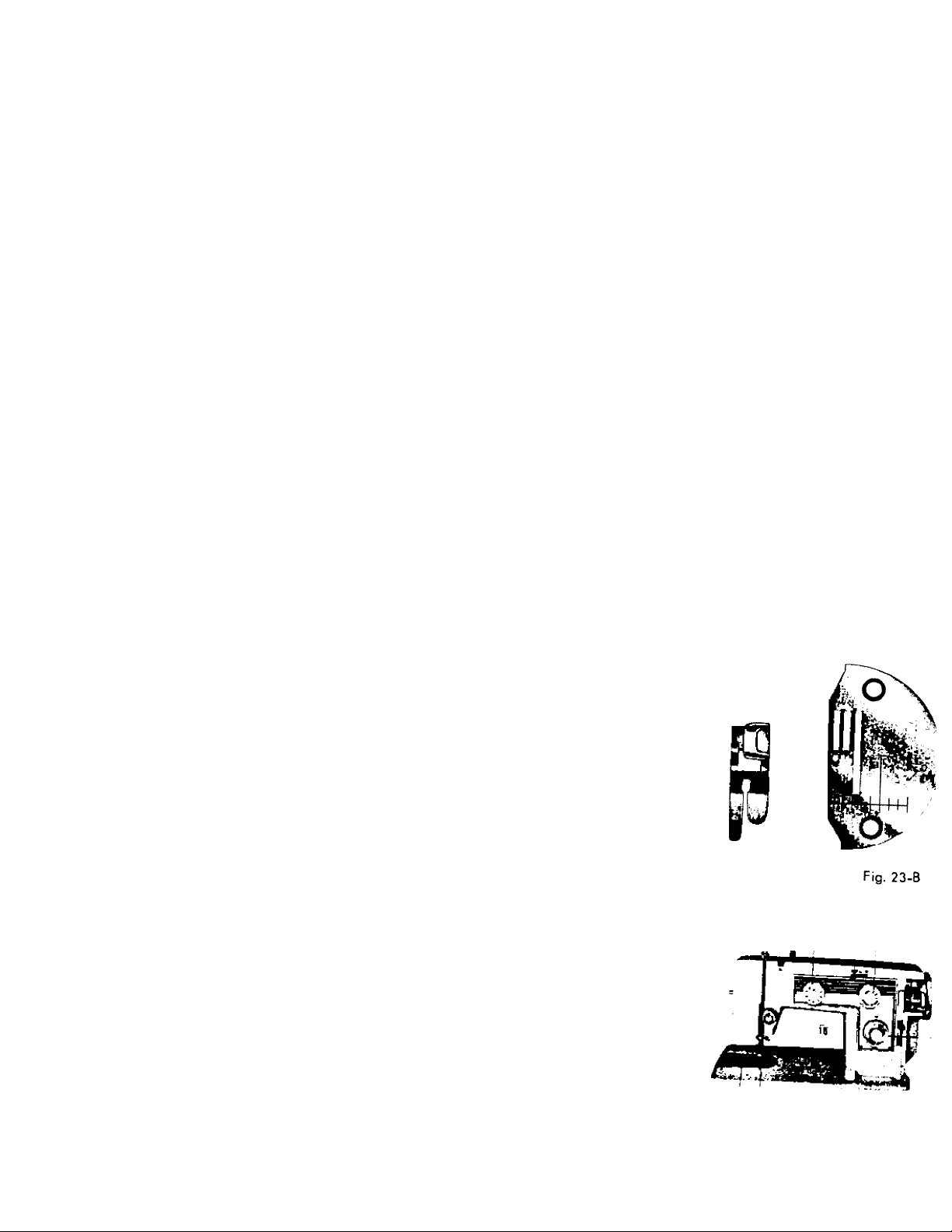
For straight sewing on fine fabric or very soft material
you may wont to use the straight stitch presser foot and ’
•he stra.gh, stitch needle pbte which ore included in your
accessory box. Both have narrow needle slots.
Changing the Presser Foot and Needle Plate:
(1) Presser Foot
(A) Loosen presser foot clamp screw (18, Fig. 24)
and remove zigzag presser foot.
straight stitch presser foot (Fig.
(2) Needle Plate
(A)
Slide cover plate (l6, Fig. 24) 'o the left as for
as possible.
(B)
Remove screws hoWing needle plate (|5 pia 2 4)
to bed plate. ’
(C)
Remove zigzag needle plate.
(D)
Rephce with straight stitch needle plate (Fig
23-B) ■
Fig. 23-A
i y- '6;
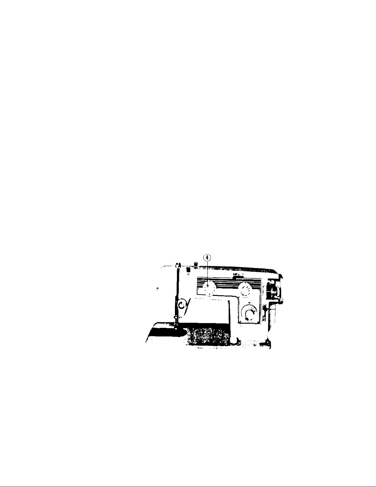
fVo 24) M decorative stitch selector diol (4.
buttonhole controle
o piote
'16 f|;
Fig. 24
Page 16

CREATIVE EMBROIDERY
15
The satin stitch (Fig. 25) which is really just a very short
Be sure zigzag presser foot and zigzag needle plate
zigzag stitch and the basis for most embroidery, is obtained
by setting stitch length control (10, Fig. 24) as near 0 as
possible without stopping the feeding action and zigzag width
(6, Fig. 24) at 4.
To stitch continuously at one width of zigzag stitching, set
zigzag width control (6,Fig.24) to chosen stitch width number.
With the machine set for a short stitch length, different
designs can be made by activating creative embroidery lever
(5, Fig. 24) sidewards from left to extreme right in its moving ^
stroke or any other combination of movements. ^
Try setting the zigzag width (6, Fig. 24) at 1 and various
numbers.
Set a rhythm for yourself and then proceed. After a while
you will become quite skillfule, varying your designs by the
speed of the machine, stitch length, and manipulation of the
Creative embroidery lever.
are in place.
Fig. 25
SAMPLE OF CREATIVE EMBROIDERY
A.
Sew a few stitches at full width, then allow lever to
spring back to 0 for a short period. Count, if necessary, to establish o rhythm.
Set zigzag with at 2 then move creative embroidery lever slowly back and forth between left
and right.
C.
Set zigzag width at 1. Gradually move lever from left to right, allowing at to snap back quickly.
D.
Set zigzag width at 4, stitch length at 1 | . Do a few zigzag stitches, drop feed for 3 or 4 stitches,
then raise it again, by operating the feed knob rhythmically it is not nessessary to count stitches.
Fig. 26
Page 17

16
stitche. P J fi; to 4, take 3 or 4 stitches, leave needle in fabric left of
lick to make next daisy petal . Continue until flower design is complete
Lock threads by settmg st,tch width ot 0 and taking 3 or 4 st.tches ,n center of dLign.
EMBROIDERING WITH A HOOP
It is easy to follow a stamped design or to
work free hand when embroidering or monogram'"9. See Fig. 27 . Release the pressure from
the fool by pressing down on the snap lock ring
darner. Set the drop feed button at “DOWN”
position oil the way.
Stretch the fabric in an embroidery hoop, and
place under the needle after removing the presser
foot. Set the stitch width at the size you prefer
and lower the presser bar lifter. Then operate the
machine at a rather high speed while moving the
thTneedT^ be sure to keep fingers out of
the path of
ShouW you encounter skip stitches, the fabric is not stretched tight enough or a darning sprina
IS needed (see attachments available from your dealer illustrated in the back of this bookf. ^ ^
DARN OR MONOGRAM WITHOUT HOOP
ir embroidery hoop, leave zigzag presser foot in
.
....................... “■ •"
wr£r,„ir„Z.,°; " *'• b. h.w ,o„, o, ,k,pp.d .p,Ph=.
Page 18

BUTTONHOLES
To establish the correct length buttonhole required add M
Inch to the cutting space for bar tacks.
To obtain the length of the cutting space, the opening
through which the button passes is measured by adding
the width “a” and thickness “B" of the button (Fig. 29) .
First mark the beginning and end of the buttonhole on
the fabric with a basting line or tailor's chalk. Make one
or two buttonholes on scrap fabric (foibwing directions
below) to be sure the machines adjustments are correct.
(1) Set decorative stitch indicator at manual position.
(2) Set stretch stitch control lever at "M'!
(3) Replace presser foot with special purpose buttonhole
foot. '
It provides maximum visibility and allows closely spaced
stitches to feed evenly (Fig. 28) .
(4) Set stitch length control at the buttonhole position.
(5) Turn buttonhole control to position Number 1.
This will set the width of the buttonhole sides.
i
------
A—►
17
-
Fig. 29
jj
Eli
P ^
e||
P J|
/
Fig . 3 0
Page 19

18
BUTTONHOLES
Lower needle carefully into the mark on the fabric indicating the buttonhole. (Fig.
(6)
(Fig. 30, Step 1 in page 17). Sew length of buttonhole.
With needle out of the cloth, set buttonhole control to 2-4 position sew four or five
(7)
bar tack stitches. (Fig. 30, Step2) .
With needle out of the cloth, set buttonhole control to position Number 3. This will
(8)
set the machine to sew in reverse. (Fig. 30, Step3) to return to top of buttonhole.
With needle out of the cloth, turn buttonhole control back to 2-4 position. Sew four
(9)
or five bar tack stitches. (Fig. 30, Step4) .
Set buttonhole control at 0 position, extreme left, and take two or three stitches to
(10)
fasten bar tack to prevent ravelling.
Cut the buttonhole opening with seam ripper, being careful not to cut the stitching.
(11)
If you pbn to make buttonholes on sheer or soft material, place tarlaton or
paper under fabric which can be torn away after stitching.
When making additional buttonholes, be sure to return the buttonhole control
lever to 0 and back to the number 1 position to put the machine in forward
stitching.
Page 20

Fig. 31
DECORATIVE STITCHES
To select stitch design:
1. Move creative stitch lever (5, Fig. 31) to the right and hold it.
2. Move decorative stitch selector dial (4, Fig. 3l) to desired design.
3. Return creative stitch lever to the left.
4. Set stitch length control ot desired stitch length.
5. Set zigzag width control (6, Fig. 31) at "o".
6. Set the stretch stitch control lever (ll.Fig. 31) at M.
19
Page 21

20
BLIND STITCH HEM
Use standerd zigzag foot. (Fig. 32)
Set stitch length control between number 2 and 4.
Set decorative stitch selector dial (4, Fig. 1 in page 2) at — .
Blind Hemming.
Blind stitch hems provide a durable hem finish that is almost
invisible and comparable to hand sewing.
Prepare the garment in the same manner as for hand hemming.
Fig. 32
STEP
1
Step 1. (Fig. 33) If hem with folded edge is used make first fold
STEP
2
STEP
3
STEP
4
COMPLETED
deep.
Step. 2. Turn hem to the depth desired and baste from upper edge. Press in place.
Step 3. Fold hem back toward right side of garment leaving extended.
Step 4. Phce material under presser foot, sew with stitch length set to suit material being sewn
and make a side wise stitch about every of an inch of sewing.
Fig. 33
Page 22

MANUAL OPERATION
Be sure standard zigzag presser foot and zigzag needle
plate are in place and machine is set for manual operation
Use tor: '
OVERCASTING WORN EDGES
Zigzag stitch along the worn edges, catching the fabric as
the needle swings to the left, and allowing the needle to just
pass over the edge of the fabric on the right (Fia 371
PATCHING
Machine bastes patch into place by placing fabric under
hole or worn area which has been cut away. Then zigzag
applique overcasting around edge of hole.
Fig. 36-Baste design to fabric and zigzag stitch following
the shape of the design outlining it entirely and remove excess
material on the outer edge by trimming it away after stitching.
Fig^ 38-Baste design to fabric and overcast a zigzag stitch
around the design outlining it entirely.
Hundreds of other uses will become apparent as you con
tinue to use the machine. Also, for best result set speed
control slower when sewing around contours and faster for
straight lines.
21
Fig. 36
Fig. 37
Fig. 38
Page 23

22
SEWING ON BUTTONS
1. Remove hinged presser foot and attach button sewing foot.
(See Fig. 39.)
2. Set drop feed control at “DOWN” position all the way. (Fig.
3. Set zigzag stitch width stop at 0. Place the button so that
its left hole comes directly under the needle, then gently
lower the presser foot. (Fig. 40).
4. Move zigzag stitch width stop until the needle comes down
exactly over the right hand hole in the button. (Fig. 41).
Turn the hand wheel slowly by hand to be sure the needle
enters both holes in button without deflecting needle, correct
width if necessary.
5.
When needle goes into the center of each hole,
machine at medium speed, making six or eight
stopping with the needle in the left hole.
6. To lock the zigzag stitch and prevent ravelling, set the
stitch width at 0, and take a few stitches in the same hole.
If you wish you may place a rounded toothpick over the
button, between the two holes, and sew button to fabric
in regular way.
Remove the toothpick and wind thread under the button,
forming a shank to fasten.
Apply the above method to sew on buttons with four holes,
hooks and snaps, etc. If a four hole button is to be sewn,
follow the same procedure as for the two hole button.
Now lift presser foot slightly and move fabric to permit
stitching the remaining two holes. Hooks, snaps, etc., are sewn
to the fabric with the same procedure as for sewing two hole
buttons.
run the
stitches,
Fig. 40
Fig. 4t
<0^
Fig. 42
.
Fig,..43
..
Page 24

Fig. 44
STRETCH STITCHING
To sew a reinforced seam that will considerably stretch more than the fabric used, set the stretch
stitch control (11. Fig.44) at the S" position and the stitch length control (lO) at the longest possible
stitch (Number 5) to behave the mechanism to stitch same 3/32” (2 mm) stitch length in both
forword and reverse, completly releasing from the ordinary stitch length control mechanism.
With the zigzag width control (6) at higher number than 1, Rick-Rack (zigzag) stretch stitching
is performed.
With the zigzag width control (6) at 0 and the decorative stitch selector dial
the stretch blind hem stitching is performed.
A reinforce seam that will stretch is the most wanted feature in a sewing machine today.
Its uses are almost unlimited and the more you use your machine the more it will become
apparent to you.
Note: Do not set stitch length control at any other position than 5.
at
23
Page 25

24
ACCESSORIES
1. plastic Oiler (Sealed and Filled)
2. Package of Needles (5)
©I
j II f i
@ ® ® @
o ®
3. Large Screw Driver
4. Small Screw Driver
5. Bobbins (3)
6. Fell Washers (2) (for spool pins)
7. Quilter Guide
8. Cloth Guide
9. Button Sewing Foot Fig. 34
10. Prong Type Buttonhole Foot
11. Presser Foot for Straight Sewing
12. Narrow Hemmer
13. Thumb Screw
14. Needle Pbte for Straight Sewing
(graduated)
Page 26

HOW TO USE ACCESSORIES
Narrow Hemmer; With needle at its highest position replace regular
presser foot with narrow hemmer (Fig. 45) being sure to tighten it securely
in place. Set decorative stitch control (SFig.l) at straight stitch position
and zigzag stitch width control at 0 for straight stitched hem or at number
3 for zigzag stitched hem. Set stitch length control to suit.
For a plain narrow hem make a 'k inch double fold
for about two inches along edge of fabric. Hold each
end of the two inch fold, slip underneath hemmer. Bring
fold up into the scroll of hemmer, draw fabric forward to
end and fasten with point of needle. Lower presser bar
lifter. Gently pull end of thread as you start stitching
(Fig. 46 for straight stitched hem, Fig. 47 for zigzag stitch
ed hem).
Guide material slightly to left and it will take a double
turn through scroll.
The narrow hem provides an excellent finish for edges
of ruffles or any other dainty work.
25
Pig. 45
Fifl. 46
,M.T
Fig. 47
Page 27

26
LACE TRIMMED HEM
To sew a narrow hem and attach lace in one stitching, insert
bee in the sbt next to needle (Fig. 48) sew hem as above, guiding
bee under needle and hem into scroll. Rickrack may be used in
the same way.
LACE EDGE WITH INVISIBLE STITCHING
Hold bee 14 inch from raw edge on right hand side of fabric.
Insert both in scroll os for pbin narrow hem (Fig. 49) let hem
roll over and sew in bee. When the stitching is completed the
hem is pressed on the wrong side.
FRENCH SEAM
Pbee material with right sides facing each other and the top
piece of material 3^ inch from right hand edge of lower piece. In
sert in hemmer scroll allowing hem to roll over and sew in top fab
ric making French seam. For cording effect, use zigzag stitch
wide enough to catch both edges of the narrow rolled hem and sew
________________________________________
with satin stitch. This can be
used for covering chairs and so
forth. (Fig 50)
HEMMING ACROSS
A SEAM
To hem across a seam, cut
the seam fobs at an angle so pig. 50
they will lead into the hemmer
gradually. Press seam open. Stitch across the seam at the
extreme edge to hob it together and for added firmness. It
may be necessary to pull the material slightly when hemming
over the seam. (Fig. 51)
■r . Л ■■ i
. ’ “*■' И
Fig. 51
Ч
Page 28

QUILTING GUIDE
Use this guide for making parallel rows of straight
or decorative stitching. Attach standard presser foot.
Slip U shaped holder on guide between presser foot
and thumb screw from the back and tighten screw
(Fig. 52). Adjust the curved bar for the distance
desired between rows of stitches and set so it
presses slightly on the fabric. By letting the guide ride
on the previous stitching line, successive rows wil
be
at an equal distance apart (Fig. 55),
tu
Fig. 54
SEAM GAUGE OR CLOTH GUIDE
Use the seam gauge as a guide for straight seams
and even rows of top stitching along edge of fabric
(Fig. 56)
Fasten Gauge (Fig. 53) with accompanying screw
Fig. 56
(Fig. 54) in threaded hole in bed of mochine. Adjust
to desired width.
27
Fig. 55
Page 29

28
Fig. 57
Fig, 58
CARE AND MAINTENANCE OF
YOUR MACHINE
HOW TO OIL YOUR MACHINE
Use only a good sewing machine oil, do not use any com
mon household oils.
Your machine should be oiled occasionally to keep it op
erating smoothly-how often depends on the amount of sew
ing you do.
Once a year oil your machine thoroughly as indicated by
the arrows on Figs. 57, 58 and 59.
Avoid over oiling.
Fig. 59
Page 30

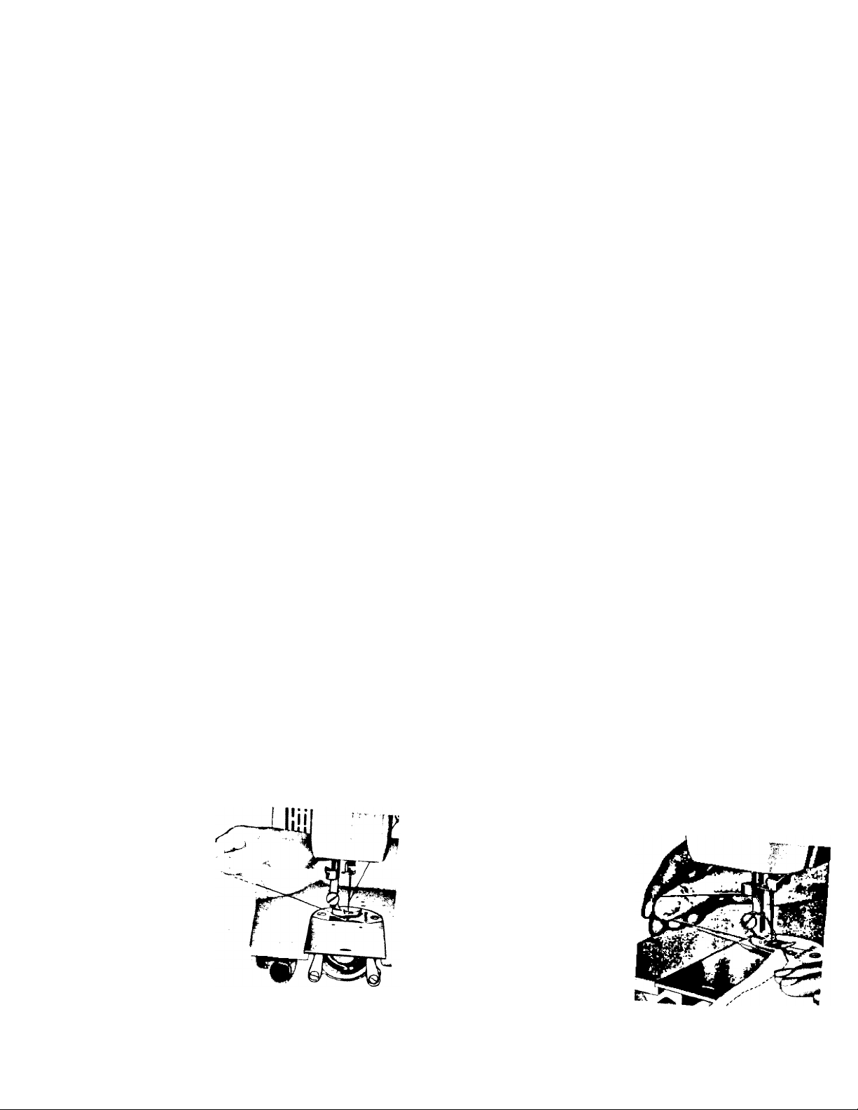
CLEANING AND OILING THE SHUTTLE
(See Fig. 60 and 61)
The stitch forming mechanism occasionally becomes
clogged with loose threads and lint. This will interfere wi
the efficient operation of the machine. Cleaning and
removal of the lint will safeguard the performance.
To remove the shuttle assembly, proceed as follows:
1. Turn the balance wheel until the needle reaches
highest position. Tilt head back on its hinges.
2. Remove bobbin case.
3. Turn the two shuttle race cover clamps (B) outward
and remove the shuttle race cover (C) and the shuttle
body (D).
4. Clean the shuttle race, the shuttle, and shuttle race
cover by removing all threads, lint, etc.
When the cleaning has been completed, proceed as
follows to replace the shuttle assembly:
1. Turn the balance wheel until the needle reaches its
highest position.
2. Pbce shuttle body, (D), in race against shuttle driver and adjust into position
wTh sh Hi" " into notch, and
w th shuttle race cover clamps, (B), making certain the clamps have' been
into position.
4. Put bobbin into bobbin case.
5. Put the bobbin case into the shuttle, fitting tongue into notch E of race cover.
'¡th
its
Fig. 61
lock into
snapped
29
position
securely
Page 31

ADJUSTING AND CHANGING “V” BELT
Fig. 63
Folbwing are the insfrucfions for adjusting and changing the V
(1) Removo
four ”
r 7,' ““'“"""W cnanging the V belt:
Fig. 64
(2)
dowi',o '*• f«' ‘■„ck., B „p ,o k»..„ b.l, p„d
(3) , To remove “V” belt:
(A) Remove top cover.
(B) loosen clutch (C, Fig. 64).
(C)
L<^sen screws "a” (Fig. 64) and move bracket “B” to its highest position
(D)
Slip belt off motor pulley and then over hand wheel '
(E)
Rephce V” belt by slipping it over hand wheel and' then over motor pulley
Adjust as noted under Mr, •> puiiey.
(F) Adjust as noted under No. 2
and
Page 32

’ I®''®'" position, tilt
head bock on hmges and remove bobbin cose.
BOBBIN NOTCH
.CASE ®0“'N I I
. LINT CLEANER
LATCH
race cover nook clamps
4 Cleon thread and lint from all ports, includ
ing race.
5--Run a drop of oil along rim of hook.
6 Replace hook, then race cover. Snap clamps
into pbce.
7-^Grosp threaded bobbin case by latch and re-
ploce, fitting tongue into notch of race cover.
RACE
Page 33

32
Skipping
Stifches
Irregular
Stitches
Uneven
Stitches
Trouble
Probable Cause
Bent needle
Needle placed
incorrectly in clamp
Too fine a needle
for thread being used
Upper thread tension
too loose
Improper threading See threading instruction, page No. 8.
Bobbin not wound
evenly
Pulling or holding
material
Not enough tension
on upper thread
Poor quality thread Try different thread.
Needle too fine for
thread being used
Discard and replace.
See instruction, page No. 6.
See needle and thread chart, page No. 4.
Tighten upper tension.
Rewind bobbin.
Avoid pulling or holding material, just guide it.
Increase tension.
See needle and thread chart, page No. 4.
Correction
Page 34

33
T roub le
Upper Thread
Breaking
Material
Puckering
Sewing Stretch
Stitch
Probable Cause
Improperly threaded
Too much tension
Starting with take-up
in incorrect position
Improper setting of
needle
Bent or eye of needle
too sharp
Bent or blunt needle
Tensions too tight
Dull needle
Stitch length too long
Machine noisy
Material will not feed
Correction
Refer to threading instructions, see page No. 8.
and rethread machine. ’
Loosen tension on upper thread by turning
thread tension knob to “LOOSE".
Always start sewing with take-up lever in
highest position.
Refer to needle setting instruction, see page No. 6.
Try a new needle.
Discard all blunt or bent needles and replace
with new.
See tension adjustment, page No. 10.
Change needle.
Reduce stitch length.
Set stitch length control at Number 5.
Page 35

34
Your sewing machine comes equipped with the basic set of accessories
described earlier in this book.
The following pages illustrate additional time saving attachments that have
been designed specifically for your machine. They are avaibble at modest
cost from your dealer. If your dealer cannot supply you with these items,
ask him to order them for you by part number. Then you will be assured
of receiving the genuine part designed for best performance with your
machine.
If a sewing machine dealer is not avaibble mail your inquiry directly to;
STANDARD SEWING EQUIPMENT CORP.
76 NINTH AVENUE
NEW YORK, N. Y. 10011
IN CANADA
STANDARD SEWING EQUIPMENT CORP.
1470 BIRCHMOUNT ROAD
SCARBOROUGH, ONTARIO 733
Page 36

SOME OF THE ATTACHMENTS AVAILABLE FOR YOUR MACHINE
35
PART # 1403
Ruffler
PART #82528
Attachment Fool
PART #76553
10
PART it 76552
Hemmers
PART #4990
Darning Spring
Ei
PART #74159
Binder
PART #76551
o
PART #1873
Cording & Zipper Foot
\_
PART #76554
Edgestitcher
PART # 76550
Page 37

36
Fig. 65
EDGESTITCHER
The edgeslilcher is used in making
dainty bee insertions, edgings and
piping.
The sbts in the edgestitcher serve
as guides in sewing together various
pieces of materbl. If you want to
sew bee, bee and embroidery, or
bee and tucked strips together, pbee
the piece of materbl that will be on
top in slot 1 (Fig. 67) and the lower
fabric in slot 4. For instance, if you
are sewing bee edging to a finished
edge of fabric, place the fabric in
slot 1 and the bee in slot 4 (Fig
67).
ATTACHMENTS
Be sure the needle positioning lever is in the
extreme left hand position.
ATTACHMENT FOOT
In order to attach binder, edgestitcher and the hem
mers, it is necessary to remove the presser foot and re
place it with the attachment foot. (Fig. 65)
Mount binder, edgestitcher or hemmers by sliding
the attachment to the left as for as possible and
' tightening the screw.
The mounting sbt enables you to sew as close to
or as far away from the edge as desired. Just move
the attachment to the correct position before tightening
the mounting screw.
Fig. 67
Page 38

Be sure to draw the lace and material under the needle and back of the edgestitcher so that
he feed will carry ,t backward as you stitch HoU the fabric in the left hand and the hce in
the right, being sure the fabric overlaps the lace slightly.
Rick-rack can be sewn to the edge of the material in the same manner
To trim with wide piping place the fabric in slot 4. and the foW of the piping to the left
nght !n ^s’lot 3 ° 2 and the foWed edge of the piping to the
Slot 5 may be used as a guide in stitching a French seam.
See Figs 68 69, 70, and 71 for suggestions on how to use the edgestitcher. There are
hundreds of other uses.
Fig. 69
Fig. 68
37
Page 39

38
BINDER
Slots on scroll of the binder ore for corresponding widths of commercially folded bi<Ts binding
The open mouth of binder scroll is used for unfolded bios strips cut ^ inch wide
■' matertal in one operation
FOLDED BINDING (Fig 74
slot. Draw through slot and under binder with strong
pin. stitching to be sure it is on the edge. Adjust
by sliding binder to right or left.
Cut folded binding to a point, (insert in appropriate
TWO-TONE BINDING (Fig 75)
Two bindings can be sewn on fabric edge also in one
operation. When two are used, always skip one size be
tween widths, inserting each in correct size slot.
HAND-CUT BIAS BINDING (Fig
Cot inch bias binding fold in half for a couple
O' joches. Cut binding diagonally toward end, almost to
fold. Slip fold into center of binder. Draw back until
cut opens and binding encircles open end of scroll. Test
stitching to be sure it is on the edge, adjust if necessary.
and 73 for sug
gestions on
how to use the
binder. There
are hundreds
of other uses.
73
74)
See Figs. 72
Fig. 74
-Ftgr-73-
Page 40

THE SET OF HEMMERS
Before attaching any of the hemmers, be sure bob
bin thread is pulled up. Then, with hemmer in place,
hold top thread loosely and turn handwheel one full
turn toward you, making a loop under hemmer. Grasp
bobbin thread with both hands and slip horizontal
ly under hemmer toward back. Bobbin thread will
catch loop and carry upper thread to back of hem
mer.
Fold material to suit for two inches along edge,
hold at each end of fold. Slip fold into guide and
up over spoon (Fig. 76). Fold hem in material back of hemmer. Draw forward
and fasten with point of needle. Pull on threads gently as you start stitching.
HEMMER SET
You can make a hem or 'ii" in width, depending upon which
hemmer you use. For a few of the many uses see Figs. 77, 78, 79 80 81
and 82.
39
Fig. 76
to end of he
Page 41

40
HEMMER SET
Fig. 77
Fig. 79
Fig. 81
Fig. 78
Fig. 80
Fig. 82
Page 42

THE ADJUSTABLE CORDING
AND ZIPPER FOOT
This attachment is used to make and
insert covered cording, and to sew in
zippers. Loosen thumb screw to slide
foot to either right or left of needle,
CORDING. Fold bias strip of fabric
over cord. Loosen thumb screw and
set foot so needle is centered in needle
hole. Machine baste cord in place
(Fig. 83—84).
Fig. 85
41
Fig. 83
Fig. 84
To sew covered cord to material, reset adjustable
foot so needle stitches' closer to cord, and on edge
of base fabric.
SEWING IN ZIPPER
Loosen thumb screw and slide foot so needle enters
center of needle hole. Guide metal of zipper along
edge of foot (Fig. 85). Stitching should be close to
zipper to allow easy opening and closing. Adjust to
sew from either right or left side, whichever is more
convenient.
Page 43

42
ADJUSTABLE CORDING AND ZIPPER FOOT
Fig. 86
Fig. 88
Page 44

f^'9- 89 Fig, 90
The ruffler will produce yards of delicate ruffling or precision pleating.
Ruffhng can also be done and sewn to another piece of fabric at the same time
This highly versatile attachment despite its wide range of use, is simple to use
Use the ruffler for making aprons, curtains, pleating a skirt, adding fullness to the bodice of
a dress etc.
Fig. 91
Page 45

44
RÜFFLER
Fig. 92
Fig. 93
Page 46

45
SEWING TIPS
When a da,nty ha,r l,ne fm.sh is par„cubrly desirable for the ,nside seams of sheer collars
facngs, and yokes, seam allowance that would ordinarily show through is eliminated by following
the seam outline with a narrow zigzag stitch.
Trim seam allowance close to line of stitching. Turn and press.
EVENLY SPACED BUTTONHOLES
To make a row of buttonholes evenly spaced and accurately stitched draw the online f
Page 47

46
SHAPING DARTS IN INTERFACINGS
Fig. 100
Cut interfacing down center between dart lines. Over
lap cut edges, matching dart lines. Zigzag stitch along
marking line from point to wide end of dart. Trim both
raw edges close to stitching.
Fig. 101
SEWING ON SHEER MATERIALS
Most fabrics need to be guided only in front of the presser foot as shown at left
. ..r., cp.,, Ui„, .,p., Fo- .„eh fp“° 7:
Fig. 102
LTk®ofXpel.TeTte,''p°lpr„‘‘"rthh°"‘' Fop, ood
Page 48

INSTALLING SEWING HEAD IN PORTABLE CASE
47
Please read these important instructions which
were written to aid you in placing your new
sewing machine in its portable case.
First, remove the foot control which is fastened
inside the base to avoid damage in shipping.
After unpacking the sewing machine unit, being
certain to take out the instruction book, guarantee
and accessory box, lay the unit face down on a
table. You will see two clamping screws A
entering head hinge holes B on the underside of
the back.
On the base you will find two head hinges C
which will fit into holes B. Lower the base onto
the sewing machine fitting hinges C into holes B.
Tighten screws A securely with a screw driver.
PORTABLE BASE
UNDER StDE or
MACHINE
To make the electrical connection draw the
two wires through the slot in the partition of
the base.
Plug the cord labeled Motor” into the recepta
cle marked“Motor" on the block attached to
the outer section of the base. Then insert the other
cord into the Light" receptacle.
Place the foot control on the floor, insert plug
into a wall outlet (110-115 volts) and you are ready
to sew. But first read the instruction book to becrime
familiar with the threading of the machine,
lension adjustments and all the other features
designed to make sewing a pleasure.
PASS
MOTOR-LIGHT
LEADS THROUGH
SLOT IN
PARTITICI
lOTOR-LIGHT
MOTOR-LIGHT
BLOCK
“ PLUGS
Page 49

48
TO ASSEMBLE LEGS ON CABINET
1. Place cabinet body upside down on smooth level surface f,,.» 1,
vent marking top.) surface (use packing mote rial os cushion to pre-
2. Slip leg into position between corner blocks ond rie r
slot or hole in metal bracket. '* fitting into
3. Add wing nut and tighten securely.
Page 50

INSTALLING SEWING HEAD IN CABINET
1. Ic30sen head hinge set screws unti\ head
hinge hole is clear.
2. Till head hinge fingers up and back as
far as they will go.
3. Carefully slip head onto head hinges
--making sure fingers are inserted as far
as they can go into head hinge holes.
4. Albw the head to rest in its lilledback
position.
5. Tighten both set screws securely with
screw driver.
6. Plug electrical leads into sockets bcated
inside cabinet. Cord identified with
“motor” tog must be plugged into socket
marked "motor" Untogged cord goes to
“lighi’’ socket.
49
 Loading...