

Page 1
Page 2

INDEX
[Page]
Features and Parts
Needle and Thread Chart ®
Winding the Bobbin
Upper Threading ........................................................................... ®'®
Setting the Needle ............................................................................
Threading the Bobbin Case
Placing Bobbin Case in Shuttle
Setting Stitch Length
stitch Length Chart
Sewing in Reverse
Adjusting the Tensions 14-15
Adjusting Pressure and Feed 15
General Sewing..................................................................................
Light Weight Fabrics 1®
Darning and Mending
Removing the Work ....................................................................16-17
Care and Maintenance 17-18
......................................................................
O iL
1 3
13
14-
1®
15
Changing the Belt 1®‘1®
Cleaning and Oiling Shuttle 20-21
Accessories........................................................................................
Trouble Chart
Attachments ......................................................................................
Attachment Foot ...............................................................................
Edgestitcher ......................................................................................
Binder..................................................................................................
Ruffier .................................................................................................
Cord and Zipper Foot
Hemmer
Darning Spring ..................................................................................
Buttonholer.........................................................................................
Button Sew-On ..................................................................................
Decorators .........................................................................................
Blind Stitch Hemmer.........................................................................
...............................................................................
..............................................................................................
[Page]
21
22-24
27
27
30
31
31
32
32
IT
3
j- -
Page 3
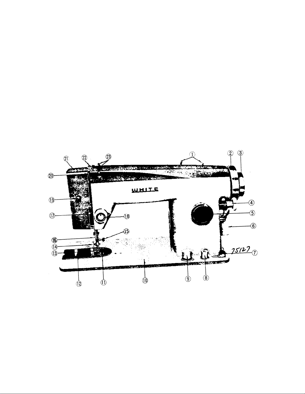
Fig. 1
\
C
s.
€>
C
€■
C
C
c
€
C
c
c
c
c
«
c
c
c
e
«
c
e
c
c
e
r
f*
Page 4

FEATURES AND PARTS (Front View)
0 Spool Pins
(D Hand Wheel
(3) Wheel Clutch
0 Bobbin Winder
® Stitch Length Dial
(D Motor Cover Plate
0 Bobbin Winding Tension
(D Push Button Reverse
(f) Drop Feed Knob
@ Bed
@ Needle Plate—Seam Guide
@ Cover Plate
@ Presser Foot
g) Attachment and Foot Thumb Screw
@ Needle Clamp and Screw
g) Needle Bar Thread Guide
It) Face Plate Thread Guide
g) Tension Regulator
g) Sew Lite Switch
g Take-up Lever
|i) Face Plate
@ Pressure Release-Darner
H Arm Thread Guides
Page 5
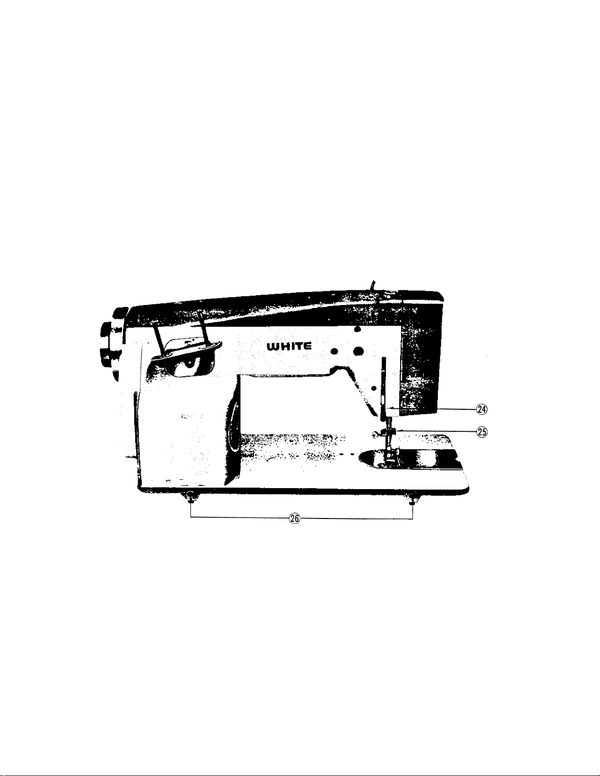
FEATURES AND PARTS (Back view)
\
\
m
»
6
c
e-
Presser Bar Lifter
Thread Cutter
mi
Fig. 2
Head Hinge Mounting Holes
Page 6

NEEDL.E-THREAD-FABRIC-STITCHING GUIDE
Fabric
Extremely heavy tarpaulin,
sacking, canvas, duck, etc.
Heavy upholstery fabric,
ticking, denim, leatherette
Medium heavy drapery
fabric, veleveteen, suiting,
felt, terry, etc.
Medium broadcloth, percale,
gingham, linen, chintz,
taffeta, sheer wool,
shantung, etc.
Sheer voile, lawn, dimity,
crepe, handkerchief linen,
plastic film, etc.
Very sheer chiffon, batiste,
lace, organdy, ninon, net,
marquisette, etc.
Needle
No
4
3
2
1
O
OO
Machine
Stitches
Per Inch
6 to 8
8 to 10
10 to 12
12 to 14
14 to 16
(Plastic film)
8 to 10
16 to 20
Cotton
Thread
10 to 30 Heavy Duty
30 to 40
40 to 60
60 to 80
80 to 100
100 to 150
Mercerized
Thread
Heavy Duty
Heavy Duty
50
50
50
Silk or
Nylon
A
A
A
Page 7
Page 8
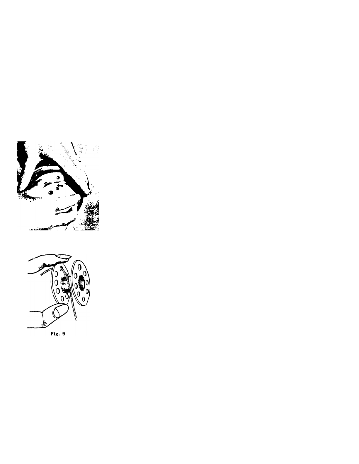
Fig. 4
WINDING THE BOBBIN
Disengage the hand wheel (2, Fig. 4) from the
stitching mechanism by turning clutch (3, Fig. 4)
toward you or counter-clockwise.
Place a spool of thread on one ‘of the spool pins.
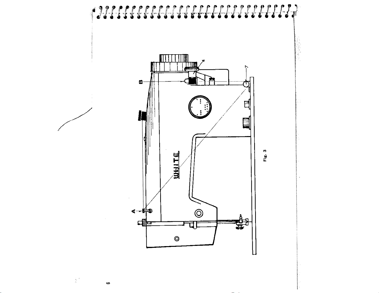
Lead thread through arm thread guides, (A, Fig. 3)
and down between tension disc, 7, at the base of
the machine.
Put end of thread through a hole in bobbin flange
(Fig. 5) from inside to outside and place bobbin,
(B, Fig. 3) on spindle of bobbin winder (4, Fig. 3)
fitting the notch in bobbin^over small pin on spindle.
Push bobbin windey pulley against hand wheel. Hold
thread end loosely and start machine slowly. Bobbin
will be released when filled.
Hold the hand wheel and turn clutch away from you
until sewing mechanism is engaged so that the
needle moves up and down when you turn the hand
wheel.
Break off loose thread end used to start the wind
ing.
Page 9
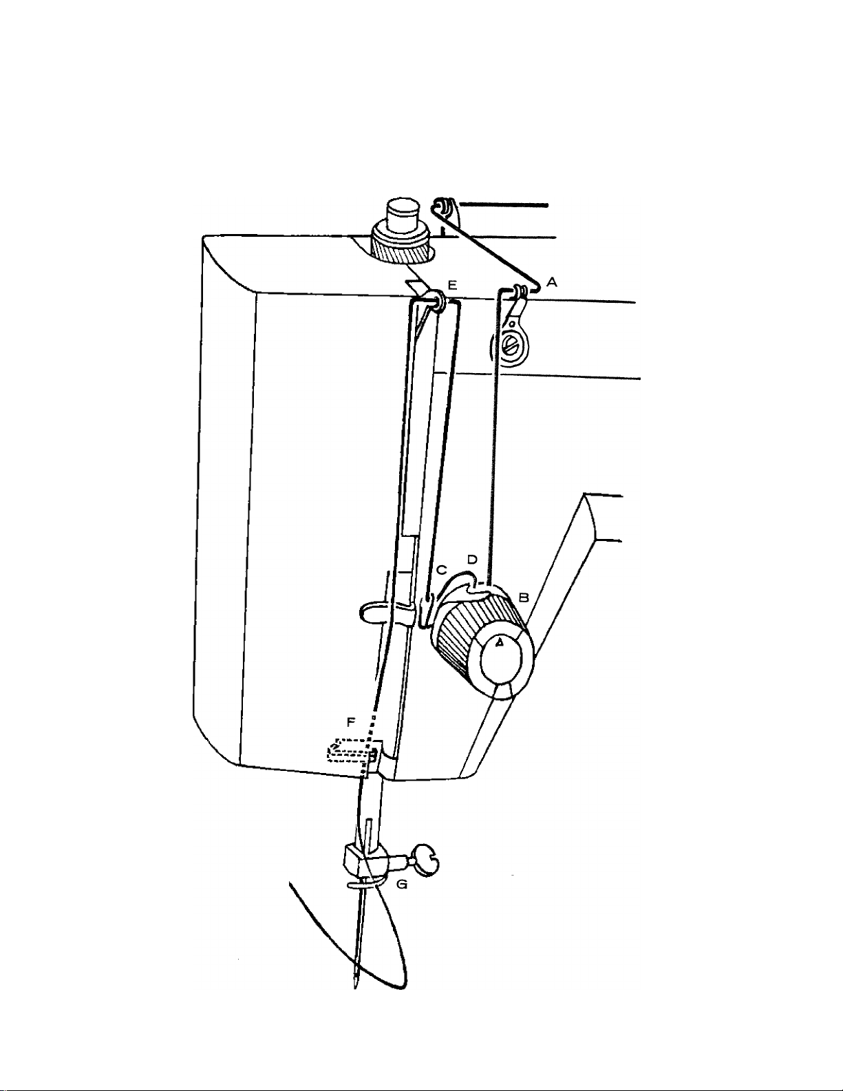
Fig. 6
Page 10
U“r*Efx I rilxE/\OIIMvi (Fig. 6)
1 . Place spool of thread on left hand spool pin.
2. Lead thread through upper thread guides (A),
3. down and around tension discs (B) from right
to left,
4. into check spring (C),
5. continue to pull on thread until it hooks over
hook (D),
6. up into take up (E) from right to left,
7. down into thread guide (F),
8. through the needle bar thread guide (Q) ; and,
9. into needle from left to right. Pull three or
four inches of thread through needle.
Hold the end of upper thread loosely and turn
wheel toward you until the needle goes all the way
down and comes back up. A loop (Fig. 7) will be
formed over the upper thread which then can be
pulled out straight. Place both thread ends under
the presser foot and draw toward the back of the
machine, leaving both threads three or four inches
long.
Fig. 7
Page 11
10
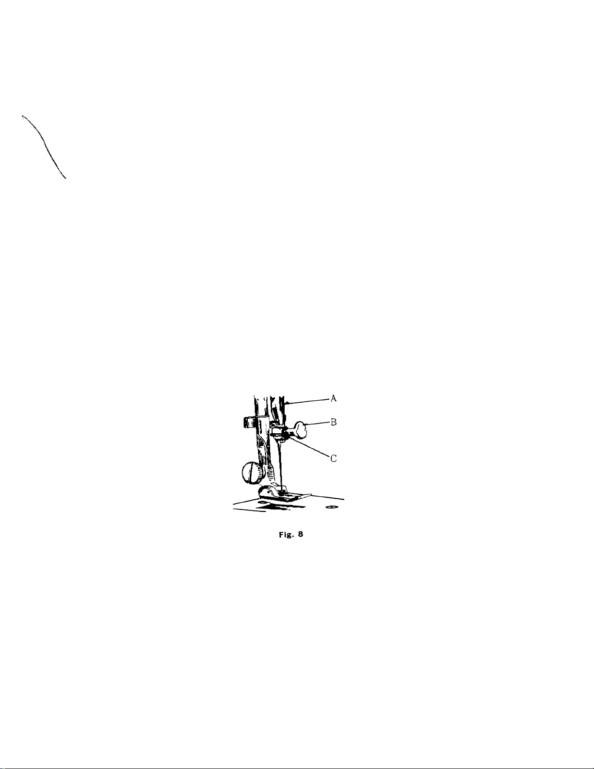
SETTING THE NEEDLE
_ii Kar ('A'l to its highest point, by turning
see Fig. S. Raise the „ B, needle can be removed or replaced
by hand. Then loosen „T) In needle clamp push It upward as far as ,t
When replacing needle ,n, needle clamp screw (B) securely a screw
Will go into needle clamp hole, tightening
C-i...
t
' %
’ I
'< t
driver.
e-
. .h, needle make one complete revolution ot the balance
*h:e?by ha^dto be sore tU needle la ,n the correct position.
«4^-
Page 12

THREADING THE BOBBIN CASE
step 1 (illustrated in Fig. 9). Hold bobbin case between thumb and forefinger of left hand,
so that the slot in the edge of the bobbin case is on top, take the bobbin between thumb
and forefinger of right hand so that the thread on top leads from left to right.
Step 2. Insert bobbin into bobbin case, pull the thread into the slot of the bobbin case as
shown in Fig. 10, and draw it under the tension spring and into the fork-shaped opening
of the spring as shown in Fig. 11.
LOT
SLOT
11
Fig. 9
Fig. 10
Fig. 11
Page 13

12
PLACING BOBBIN CASE
Raise needle bar to highest position, and lift hinged
cover plate. (See 12, Fig. 1) Hold the bobbin case
latch (D, Fig. 12), between the thumb and forefinger
of the left hand, with at least three inches of thread
running from the top of the bobbin case to the right.
Insert and center the bobbin case on the stud of the
shuttle body, (C). Be sure the bobbin case finger
(E) is opposite the shuttle race notch, (A). Press
the bobbin case (B) into the shuttle as far as
possible until latch catches on the center post of
the shuttle. Then release the bobbin case latch,
(D). Press bobbin case again after latch has been
released to make sure the bobbin case is locked
Fig. 12
securely.
Close the cover plate.
Page 14

SETTING THE STITCH LENGTH
13
The length of the stitch is regulated by the dial
shown in Fig. 13. Near O is the shortest stitch
and 8 is the longest, but the dial may be set at
any spot between markings for a variety of
lengths. Turn the dial to the right to lenghten
and to the left to shorten the stitch. The number
stitch length you choose appears under the indi
cator.
STITCH LENGTH CHART
Figures on indicator
Number of stitches per inch
O
No Feeding
(Approximate)
2
1
30
50
20
8
7
6
5
4
3
6
7
12
10
8
Page 15

14
SEWING IN REVERSE
When you wish to sew backward to tie the threads at the beginning or end of a seam,
press in the button R, 8, Fig. 1, as far down as it will go. The machine will sew backward
as long as the button is held down.
ADJUSTING THE TENSIONS
Always adjust the upper tension with the presser foot down, as the
when it is raised. To increase the tension on the upper thread, turn
right. To decrease, turn to the left.
Before adjusting lower tension be sure that the machine is
threaded correctly. When necessary to change the bobbin
tension, turn small screw (Fig. 15) on side of the bobbin
case clockwise to tighten, counterclockwise to loosen.
When the upper tensions are properly balanced, a perfect
stitch will be formed with both threads interlocking in
fabric (Fig. 16).
When the upper tension is too tight, the lower thread is
pulled up over the upper thread which is lying flat on the
fabric (Fig. 17). When the upper tension is too loose, the
upper thread forms loops over the lower thread lying flat on
the fabric (Fig. 18).
tension
dial (Fig
Fig. 14
is released
14) to the
c
c
c
c
c
c
c
r
c
c
c
e
0
0
0
0
0
0
#
Page 16

Fig. 17
Fig. 18 i
15
Fig. 15
ADJUSTING PRESSURE AND FEEDING OF FABRIC
GENERAL SEWING
Usually for normal sewing the pressure bar cap or darner release,
22, Fig. 19, is at Its lowest position and the drop feed knob is
turned to “HI” position. Fig. 20.
SEWING THIN OR LIGHT WEIGHT FABRICS
When lighter pressure is required to sew satisfactorily on thin silk
or filmy material, the pressure cap should be about halfway down.
Release all the way by pressing the snap lock, (A, Fig. 21) and
then press cap (B) down again to halfway spot. Lower the feed
slightly by turning the black dot on the knob to ”LO” position.
Fig. 19
Fig. 20
Page 17

darning and mending
n ord.r W move the fabric freely m any direction tor d.rmng
>nd mending, release the pressure cap B completely by press
ing down on the snap lock, (A, Fig, 21).
Turn the knob to-DN" position, which drops the feed we
below the needle plate. To return feed to normal, return knob
to “HI”.
PREPARING TO SEW
Have taKe-up lever at highest point before starting to se
Fig. 21
DO not try to help the feeding by pulling the material as this
may deflect the needle and cause it to break.
never run machine without material under the presser foot
Place material and threads in position under the presser foot and lower ^he P^^^
Turn the hand wheel toward ;Vt:;:,:V:n. Tt " n:. necessary to touch the
to begin sewing. By having fvontrol The speed of the machine
hand wheel to start the machine. Vou merely pres, “ ° J
is regulated by increasing or decreasing
. ■ т^oт'I-f»asina the amount of pressure exeneu un
Page 18

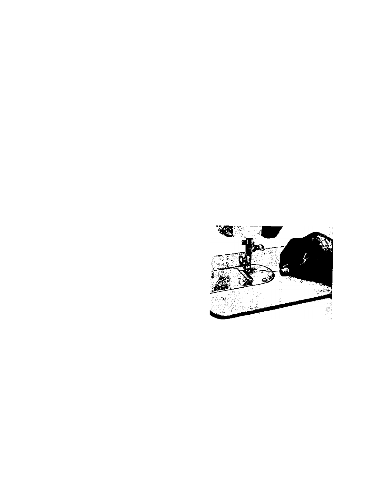
EMOVING THE WORK
sure to stop the urachlne when the thread take-up
sition Now raise the presser foot and draw the fabric back and to the left, Fig. 22 an
ss the threads over the thread cutter. Pull down slightly, holding thread in both hands,
as not tötend the needle, Fig 23. Leave the ends of thread under the presser foot.
17
Fig. 23
iARE AND MAINTENANCE OF YOUR MACHINE
OW TO OIL YOUR MACHINE
our machine should be oiled occasionally to
sep it operating smoothly, how often depends
T the amount of sewing you do.
efore oiling the upper part of the sewing unit
t points indicated by arrows in Fig. 24 turn
and wheel toward you until the take-up lever
i at its lowest point.
Fig. 24
Fig. 25
Page 19

18
Avoid over oiling: only a drop is needed at each point.
Be sure all points indicated by a red spot receive a drop of oil.
To oil mechanism under bed of machine, tip the head back on
its hinges and oil all moving parts indicated by arrows in Fig.
25.
For oiling needle bar mechanism, open face cover plate. Fig.
26.
HOW TO CHANGE THE BELT
«.
c
c.
c
c
c
c
c
c:
c
«
«
e
e
©
Fig. 27
Fig. 28
Fig. 29
Page 20

If it should ever become necessary to replace the belt on your machine, the hand wheel
must first be loosened and moved out.
To do this, follow these instructions:
1 . Remove clutch nut (A) in center of wheel by taking out the small screw (B) near the
edge. Fig. 2T. Turn nut counter-clockwise until it can be lifted off.
2. Before moving the hand wheel, note the position of the washer, (C, Fig. 28), which fits
under the clutch nut. It may fall out when you are changing the belt.
3. Remove motor cover plate (6, Fig. 28) by loosing screws (E, Fig. 28).
4. Pull hand wheel away from the machine carefully. Fig. 29. Pull it just far enough to
make the grooved section which holds the belt accessible.
5. Slide old belt over hand wheel and over pulley on the end of motor.
S. Slide new belt into grooved section and over motor pulley.
7. Push hand wheel back against the machine.
8. If washer (C) has fallen off, replace so that the lips (D) are pointing toward the clutch
nut.
9. Replace nut and tighten screw securely.
10. Replace motor cover plate and tighten screws securely.
19
After doing this, turn the clutch toward you to disengage the sewing mechanism. If the
needle still moves up and down as you turn the hand wheel, again remove the clutch nut.
Give the washer a half turn and replace the nut.
Page 21

20
»
CLEANING AND OILING THE SHUTTLE (See Figs. 30 and 31)
The stitch forming mechanism occasionally becomes
clogged with loose threads and lint. This will interfere
with the efficient operation of the machine. Cleaning
and removal of the lint will safeguard the performance.
To remove the shuttle assembly, proceed as follows;
1 . Turn the balance wheel until the needle reaches its
highest position. Tilt head back on its hinges.
2. Remove bobbin case (A), Fig. 30.
3. Turn the two shuttle race cover clamps (B) down
ward and remove the shuttle race cover (C) and
shuttle body (D).
4. Clean the shuttle race, the shuttle and shuttle race
cover by removing all threads, lint. etc.
5. Apply a drop of oil with finger tip to outer edge of shuttle.
When the cleaning has been completed, proceed as follows to replace the shuttle assembly:
1. Turn the balance wheel until the needle reaches its highest position.
2. Place shuttle body, (D), against shuttle driver and
adjust into position.
3. Hook shuttle race cover, (C), over hinge pin at lower
edge into notch, and lock into position with shuttle
race cover clamps, (B), making certain the clamps
have been snapped securely into position.
4. Put bobbin into bobbin case.
5. Put the bobbin case into the shuttle race fitting tongue
into notch (E) of race cover.
Fig. 30
A C
5
6
c
c
C-'
C'
c
e-
0-:
Page 22

21
ACCESSORIES
' ‘-t
■ 7 <r^/6 f
ISf
y I o
5
o
1 . Plastic Oiler
(sealed ^nd filled)
2. Package of Needles (5)
3. Large Screw Driver
4. Small Screw Driver
5. Felt Washers (2)
(for spool pins)
6. Bobbins (3)
Fig. 32
Page 23

c
22
TROUBLE CHART
Trouble i Probable Cause
If Machine
Binds
Thread or lint in
raceway
With take-up lever in highest
head back on hinges and remove bobbin
CLAMPS
BOBBIN
^ i
LATCH
T urn
CASE
\
/
BOBBIN
clamps
^RACE
HOOK
RACE COVER
outward and remove race
cover.
3 Remove hook.
4. Clean thread and lint from all parts, in
cluding race.
5. Run a drop of oil along rim of hooK
6. Replace hook, then race cover. Snap
clamps into place.
7. Srasp threaded bobbin case ®n^
replace, fitting tongue into notch of
cover.
»
¥
«
i
s
Page 24

23
I
I
T rouble
Probable Cause Correction
I
I
i
i
i
i
i
i
i
•
Skipping
stitches
Irregular
stitches
»
»
Uneven
#
stitches
Bent needle
Needle placed
incorrectly in clamp
Too fine a needle for
thread being used
Upper thread tension
too loose
Improper threading
Bobbin not wound
evenly
Pulling or holding
material
Not enough tension on
upper thread
Poor quality thread
Discard and replace.
See instruction page No. 10.
See needle and thread chart, page No. 5.
Tighten upper tension.
See threading instruction, page Nos. 8 and 9.
Rewind bobbin.
Avoid pulling or holding material, just
guide it.
Increase tension.
Try different thread.
a
Needle too fine for
thread being used
See needle and thread chart, page No. 5.
Page 25

24
%
Trouble
Upper
thread
breaking
Material
puckering
Probable Cause
Improperly threaded
Too much tension
Starting with take up
in incorrect positon
Improper setting of
needle
Eye of needle too
sharp
Bent or blunt needle
Tension too tight
Dull needle
Correction
Refer to threading instructions see page Nos.
8 & 9 and rethread machine.
X^oserTtensiorTon upper thread by turning
thread tension knob to left.
Always start sewing with take up lever in
highest position.
Xefe7t^^ieedle^etting instructions see
page No. 10.
Try a new needle.
^XiscardTlTblunt or bent needles and replace
with new.
See tensions adjustment page No. 14.
Change needle.
%
B-
■ %
: ^
^ %
: 1
-,
stitch length too long Reduce stitch length.
Page 26

25
Your sewing machine comes equipped with the basic s
pas- must! add.ti^
h«ve been designed specifically for your machine. They are ava.
a. modest oost from your dealer. If your dealer cannot »'th
those items, asK him to order them for you by part number. Then y
Win brass:red Of recelvlns the senulne part designed for best per
formance with your machine. directly
„ a sewing machine dealer is not available mail your inquiry dire y
to:
• \A/i+h bsisic s©t of a.cc©ssori©s
WHITE SEWING MACHINE COMPANY
11750 BEREA ROAD
CLEVELAND, OHIO 44111
In Canada:
WHITE CONSOLIDATED INDUSTRIES, LTD.
1470 BIRCHMOUNT ROAD
SCARBOROUGH 733, ONTARIO
Page 27

26
C
c
SOME OF THE ATTACHMENTS AVAILABLE FOR YOUR
MACHINE
Fig. 33
«^PART ; 4990
Darning Spring
<.^PART S 76554
Edgestltcher
o oi
CD!
'■te--
K" PART S 76550
^PART S 82528
Attachment Foot
PART i 76552
e-PART i 1403
Ruffler
PART i 76552
^PART ; 74159
Binder
Tr PART i 76551
Hemmers
&■
6-
c
c
c
c
c
c
c
c
c
c
e
e
c
e
e
c
e
r
f
c
c
c
Page 28

\
ATTACHMENT FOOT
In order to attach the binder, edgestitcher and the hem
mers, it is necessary to remove the presser foot and
replace it with the attachment foot Fig. 34.
Mount binder, edgestitcher or hemmers, sliding the
attachment to the left as far as possible and tighten
screw.
The mounting slot enables you to sew as close to or as
far away from the edge as desired. Just move the at
tachment to the correct position before tightening the
Fig. 34
mounting screw.
THE EDGESTITCHER
The edgestitcher is used in mak
ing lace insertions, edgings and
pipings. The slots serve as
guides. To sew lace edging to
fabric, place the material you
want on top in slot 1 and the
other piece in slot 4, Fig. 3©.
To trim with a wide piping, place
the fabric in slot 4, and the told
of the piping to the left in slot
3, for a narrow piping, place the fabric in slot 2 and the folded edge of the pi
right in slot 3.
Slot 5 may be used as a guide in stitching a french seam.
Fig. 35
27
Fig. 36
ping to the
Page 29

28
BINDER
This attachment folds bias binding and applies it
to the edge of material in one operation. Slots on
scroll of the binder are for corresponding widths of
commercial folded bias binding. The open mouth of
binder scroll is used for unfolded bias strips cut
15/16 inch wide.
FOLDED BINDING
Cut a point on folded binding, insert in appropriate
slot. Draw through slot and under binder with strong
pin. Test stitching to be sure it is on the edge.
Adjust sliding binder to right or left.
(Fig. 37)
Fig. 37
#
c
c
6.
e
c
«
c
c
C:
C
C
C
TWO-TONE BINDING
(Fig. 38)
Two bindings can be sewn on fabric edge also in
one operation. When two are used, always skip one
size between widths, inserting each in correct size
slot.
HAND-CUT BIAS BINDING
(Fig. 39)
Cut 15/16 inch bias binding fold in half for a couple
of inches. Cut binding diagonally toward end, al
most to fold. Slip fold into center of binder. Draw
back until cut opens and binding encircles open end
of scroll. Test stitching to be sure it is on the edge.
Adjust if necessary.
€
€
Fig. 38
e
e-
Page 30

RÜFFLER
The ruffler will produce yards of delicate ruffling or precision pleating. Ruffling can also be
done and sewn to another piece of fabric at the same time. This highly versatile attachment,
despite its wide range of use, is simple to use. Use the ruffler for making aprons, curtains,
pleating a skirt, adding fullness to the bodice of a dress, etc.
29
Fig. 39
Fig. 40
Fig. 41
Page 31

30
THE ADJUSTABLE CORDING AND ZIPPER FOOT
This attachment is used to make and
insert covered cording, and to sew in
zippers. Loosen thumb screw to
slide foot to either right or left of
needle.
CORDING. Fold bias strip of fabric
cover cord. Loosen thumb screw and
set foot so needle is centered in
needle hole. Machine bastes cord in
place (Fig. 42).
To sew covered cord to material,
reset adjustable foot so needle
stitches closer to cord, and on edge of base fabric.
SEWING IN A ZIPPER
Loosen thumb screw and slide foot so needle enters
center of needle hole. Guide metal of zipper along
edge of foot (Fig. 43). Stitching should be close to
zipper to allow easy opening and closing. Adjust to
sew from either right or left side, whichever is more
convenient.
Fig. 42
Fig. 43
Page 32

»
t
I
►
>
»
»
»
»
I
I
i
i
i
»
»
»
THE SET OF HEMMERS
Before attaching any of the hemmers, be sure bobbin
thread is pulled up. Then, with hemmer in place, hold
top thread loosely and turn hand wheel one full turn
toward you, making a loop under hemmer. 0rasp bob
bin thread with both hands and slip horizontally under
hemmer toward back. Bobbin thread will catch loop
and carry upper thread to back of hemmer.
Fold material % inch for two inches along edge, hold at
each end of fold. Slip fold into guide and up over spoon
Fig. 44). Fold hem in material back of hemmer. Draw
forward to end of hem and fasten with point of needle.
Pull on threads gently as you start stitching.
DARNING SPRING
HOW TO ATTACH
Remove presser foot, unthread needle, place darner
spring on needle and slip hook up over needle clamp.
31
Fig. 44
»
Fig. 45
Page 33

32
PART 5 2013
Fig. 46
Д ^
MAKE BUTTONHOLES Fig.
b-r
ТГеТс^пГ:-'
ГГе Гоп .e ---VOU -^no, e.n ^
fabric... the button ° ® buttonholes ranging
with five Vl/16" in both the straight
,„ no. you have used this ButtonГоГуГ:,realize there's no greater tlnr, saving
accessory hn+tonholes are also available.
Keys for other size buttonholes ar
fnr vour sewing machine,
.r о'Г- vr.
BUTTON SEW-ON (Fig. 47
• z,++achment which will convert
::Гг r:hinrr:r?t thatwm ,ew buttons of vanous
:Г;"are^L\ruГn-er•°.rГofthea^
:‘сГу,::аГ:пГ:п:аГа:рГаг1пд.аппег.
')
PART S 7622
Fig. 47
Page 34

»
>
decorator (Fig- -*8)
»
I
I
I
i
»
BLIND STITCH HEMMER (Fig- *»)
Fig. 48
PART ; 76022
33
With the wonderful new decorator your "'»='^1"®
converts to a nraeter-oontroiled
broidery ntagic ,. ,;<j you're ready
the Dresser foot, attach the
to r^atre eight different decorative P*"“'"=;
pattern of course, has many variations ,n
Tenoth. All designs are built right into the deco
ratoA reducing your effort to a m,nimum...and you
use ordinary thread, standard needles.
]•
*-,»>■
With the use of this attachment you »f« *bl^e *° quichly
produce invisible stitched hems oh
draperies, etc. Also save many tedious hours of hand
work and give your sewing that P''<4f
Just fold your material and let the attachment take over.
^"*4
PART ; 7622
Fig. 49
Page 35

34
IVI E IVI О
»
^ ,
€r-
&
c
&
c
e
®"
C
©'
c
e
e
e
e
 Loading...