

Page 1
5 STITCH. Attachments
BOOK 12
ik0.fl
DIRECTIONS
iBii
F@r Usiog tlia
White Rotary Sewing ;
Machine
10 M 6-20
.
MANUFACTURE© BY
W'Mte Sewing Machine Company
Cleveland, Ohio, U. S. A.
Page 2

Any needle offered for sale or use in
yyjfti'iia'aij
,eOI.D SWAGESi
IT'OlMACHiNE/
iraVJVEEDLES/f
Fae-sTmife of genuine
Trade Mark Label,
trade mark registration on the outside label. Accept no other.
fit
fit
box, and the express or freight charges Prepaid.
per to write and mail us a letter upon the same day he sends the
machine, and inform us how, and by what line he ships; also.'write
full particulars as to the trouble with the machine, and give us the
Machines Returned to Us for Repairs
ShoGd have the name and address of the shipper inside of the
|n addition to putting the address in the box, we want the ship
White sewing machines, without the name
WHITE F.R. stamped on the shank is "bogus” .
Many of them will cause the machine to
skip stitches, break thread, injure your ma
chine, and invalidates the guarantee for free
repairs. ''Genuine White” needles have the
name “White F. R.” stamped on the
ahank. They are put up and sold only in
packages with notice of the United States
PLATE NUMBER, Found On Bed Under Bobbin Winder,
Close To Arm.
Be sure and give 'explicit directions how and where to return the
machine.
il-
*
m
Page 3

INSTRUCTIONS
for using the
White Rotary Sewing Machine
Never run Machine with needle threaded without goods
under presser-foot. Run Machine so that upper side of hand
wheel moves from gou.
TO SET NEEDLE
Raise the needle-bar to its highest point; loosen the thumb
screw and press it to the left to permit the shank of the needle
to pass up between the clamp and needle-bar as far as it will go,
flat side to the right—the needle being flattened on one side so
it will set itself perfectly, then fasten securely by tightening
thumb-screw.
To avoid loosening of the needle, always use a screw driver
to fasten the same, the needle nut being slotted for that purpose.
The needle, when descending, should pass central in the
needle hole from front to rear, but close to the right side of the
hole, as it prevents the needle from glancing into the race and
being caught by the shuttle.
NEEDLES AND THREAD TO BE USED
The MOST IMPORTANT consideration is to buy and use perfect
needles—not bent, nor blunt points.
When ordering needles for this machine, be sure to ask for
the genuine White Rotary flat shank needles which are stamped
on the shank “White F. R.” Imitation or “just as good” needles
will cause trouble. Get the genuine White.
Cut of White Rotary flat shank needle
The size of the needle should conform to the size of the
thread and both be suitable to the material sewed. Use as fine a
needle as will permit the thread to pass freely through the eye.
The following index will show the size of needle, thread and
silk to be used.
For colored thread use needles one size larger than given
in index above.
showing exact length.
COTTON THREAD.
150 to 800
90 to ISO
70 to 90 0
50 to 70
SO to 50 C
20 to 30
SILK THREAD
000
00 0
A & Б
D
3
NO. OP NEEDLE
00
1
2
3
4
Page 4

;
;
I:
l-.iv
-
^r\ t^t^KJKrwrr* rtr\T3TJll^1 A Of?
IV/ iNjc-mv^ V Ka
FROM SHUTTLE
Eaise the take-up to its highest
point. With the thumb and sec
ond finger of left hand clasp bob
bin case as shown in cut, then lift
latch S with the third finger, when
bobbin case may be readily with
drawn from shuttle F. See page 5.
TO REMOVE SHUTTLE FROM SHUTTLE RACE
First remove the bobbin case. Turn the machine back on its
hinges, then, turn the machine in the same direction as in sewing
until the point of the needle just enters the needle plate hole;
push on rear end of latch G and at the same time pull shuttle
race cover away from shuttle and toward latch G from under pin
H; the shuttle can now be removed.
When shuttle has been removed from race be sure to clean
both and oil the race slightly before replacing. Occasionally oil
slightly in hole on race cap marked V above and pin W in
shuttle, see page 5, fig. 9.
4
Page 5
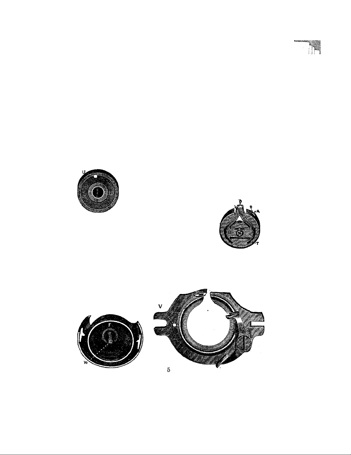
TO REPLACE THE SHUTTLE
Turn the machine in direction for sewing until the point of the
needle just enters the needle plate hole: take the shuttle by the center
JV with the left hand and place it in the race, so that point of
pin
shuttle will be from you and over arrow on thread cast off, so that
the holes in the shuttle will drop on. to the driving pins in race, then
^ replace the shuttle race coven
I DO NOT FORCE the shuttle into race. It will enter readily
when in proper position
Should the machine at any time act badly in sewing or running
it would be well to remove shuttle and dean it and the race, which
is but a moments work.
To replace the bobbin case, it need not be held as when remov
ing. but simply slip it on the pin in shuttle, with the tension project
ing upward, and push it into shuttle as far as it will go, when the
spring latch will pass over and retain it in that position.
The thread should be allowed to project about one inch from
bobbin case tension.
TO WIND THE BOBBIN
Place spool oa spool pin, pass the thread dovn. through
the rear hole in axm of cover plate, then to the left under and
over the arm down through front hole. Put the end of thread
through hole U in bobbin from inside out, place bobbin on
bobbin winder spindle, raise winder so p
belt will drive it, loosen thumb screw in
Fig, 7 Bobbin hand wheel, run the machine as in sew
ing. holding on to the end of thread until winding is started'
then break off thread and finish winding.
LOWER TENSION
Fig. 8 represents the bobbin case. To regulate the lower
tension, t-urn the screw T to the right to tighten, and to me
left to loosen the same. Fig. 3 Bobbin Case
TO THREAD BOBBIN CASE TENSION
Place bobbin in case so that thread will come from bc^hin on
same side as hole B in. bobbin case: pass thread throusii slot A to
hole B thence across opening, drawing it down under h'P C then pull
it up until thread passes out under tension spring R-
. The tension on bob
bin case should be the
same as the upper ten
sion.
0 1
if ■
Fif. 9 Shuttle
Fig. 10 Shuttle Race Cover
Page 6

DIRECTIONS FOR THREADING
Place the spool on spool pin, take the thread in your left
hand holding it taut with the right during the whole threading
operation. Pass
thread from
spool over check
spring K at top
of face and down
under point L;
now pull thread
upward until it
passes through
the eye of spring
N and into notch
O, then into end
of t a k e-u p P,
then down
through slot R in
end of needle bar
and through eye
of needle from
left to right, al
lowing about 3"
of thread when
take-up is at its highest point.
To draw up the lower thread,
raise the presser-foot, take hold
of end of upper thread and turn
the hand-wheel once around,
(moving upper side of wheel from
you) which will draw the lower
thread up through needle hole.
Pass the ends of both threads
under the presser-foot and you
will be ready to sew.
Note.—Do not run the machine with
the presser-foot down on the feed withoat cloth under it. Do not pull cloth to
or from you in such a manner as to bend
needle.
THE TENSION
The illustration above represents the
Tension Regulator and Indicator for the
upper thread, an entirely new and useful
device. The half circle is marked with a
scale running from 1 to 8, with the word
Fig. IZ
"loose” at fig. 1 and "tight” at 8,1 being
the slack and 8 the tightest tension.
6
Page 7
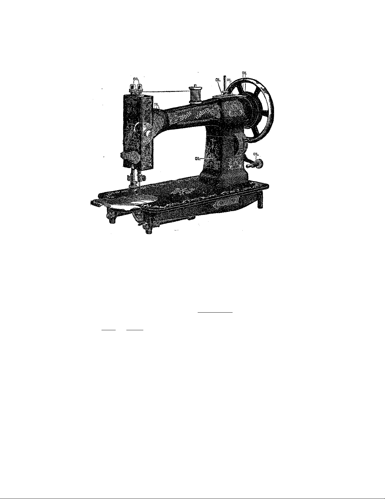
OIL PLACES AS INDICATED BELOW
V
The regulator is located at the right end of machine on the front side of arm,
TO SHORTEN stitch move the lever down. TO LENGTHEN stitch move lever up
No. 1 indicates the shortest, and No. 7 the longest stitch.
TO CHANGE THE LENGTH OF STITCH
w
TO REGULATE THE TENSION
To loosen the tension, turn the thumbscre'W on the dial to the
left which will move the pointer toward figure 1. To tighten it, turn
to the right, moving the pointer toward No. 8. By this means the
same tension can always be duplicated, thus obviating the necessity
of experimental trials, as is the case with other machines. If a tight
tension is desired, both upper and under threads must necessarily be
tight. If the upper thread is tight and the lower thread loose, tiie
upper thread will be drawn to the top thus If the low
er thread is too tight, it will be drawn straight on the bottom of goods,
thus; ' When you desire the goods to look alike on
both sides, and be elastic, balance the tension thus;
3
The tension releaser is operated by the presser-bar lifter. By
means of it, all tension is taken off the upper thread when the
presser-foot is raised, and the work can be taken out without pulling
the thread down by hand.
PARTICULAR NOTICE—The tenshn cannot is regulated when the lifter is up
because the Releaser is operated by the presser-bar lifter,
THE TENSION RELEASER
7
IB
¡!i S
;f:
m
B
fi®
I :: :
li
li
if
Page 8

TO COMMENCE WORK
In threading^ the needle and bobbin case respectively, you
should leave an end of thread about two inches in length to each.
Hold the end of the upper thread loosely in the left hand, and
with the right hand gently revolve the hand-wheel until the
needle passes to its lowest point and returns, a loop will be
formed through which the shuttle will pass, and, as the needle
ascends it will draw up the lower or shuttle thread, and the
machine is ready for practical operation.
TO REMOVE VfORK
Stop the machine with the take-up at its highest point; raise
the presser-foot with the lifter which slackens the upper thread;
then take hold of your work with your left hand and pull it di
rectly from you, keeping the top thread in the slot of the presserfoot, which will prevent bending the needle. Now raise the work
and draw the threads into the thread cutter on the presser-bar
and pull downward, which will cut the threads the proper length
to commence work again.
EXPLANATION OF DIFFICULTIES THAT SOMETIMES
OCCUR WITH BEGINNERS
If the upper thread breaks, it may be caused by the needle
not being properly set, or the machine not threaded correctly, or
the upper tension too tight, or the thread uneven and the needle
too small for it, or the needle eye too sharp, or the presser-foot
attached to the machine so that the needle rubs it in passing.
If the under thread breaks, it may be caused by the bobbin
case being improperly threaded, or too much tension upon it, or
by the bobbin being wound too full so that the thread slips over
the ends of the bobbin in the bobbin case.
If the needle breaks, it is more than likely your owii fault
caused by pulling the goods to or from you in such a manner that
the needle strikes the throat plate and is bound to break. The
needle may, however, break in trying to sew extraordinary heavy
seams when the pressure on the presser-foot is not heavy enough.
To create more pressure upon the' goods turn the presserbar nut on top of the presser-bar to the right; to decrease the
pressure turn it to the left.
If it makes loop stitches, it is most sure to be caused by too
loose tension both top and bottom.
If the machine skips stitches, the needle is either bent or not
in right position.
If the stitches are not even, it may be caused by the presserfoot not resting evenly upon the fabric sewed, or by the feed not
being high enough, or by the stitch being too short, or Dy pulling
the cloth or by using too fine a needle with too coarse or uneven
thread.
If the machine should be run without sewing and thread get
in the shuttle race making the machine run heavy, take out
bobbin case and run the machine in the wrong direction; it will
cut the thread out.
Notice.—The leather band should always be tight enough not to slip. If it
slips, or does not force the needle through thick goods, cut off a very short piece
and re-adjust the ends. The belt should not be so tight as to prevent an easy
motion of the machine.
8
Page 9
DIRECTIONS FOR USING THE ATTACHMENTS
I'M
I
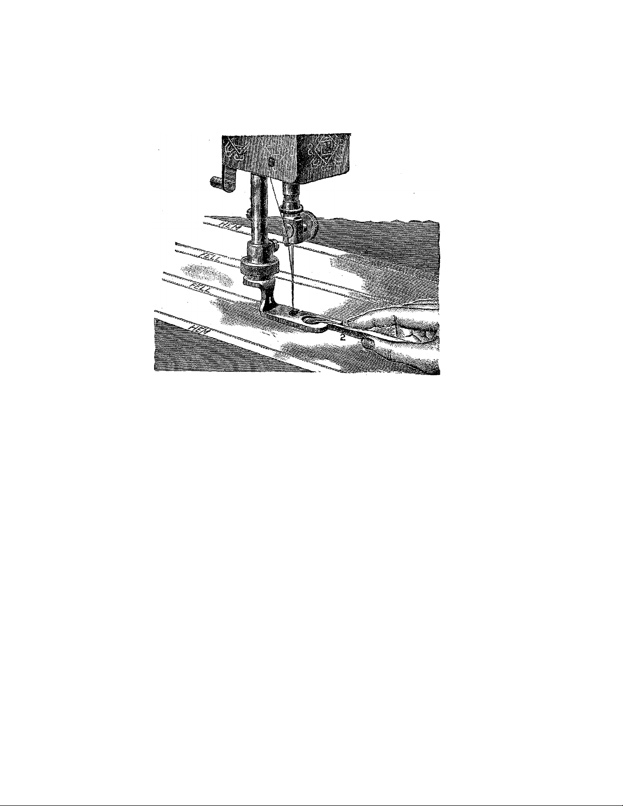
Hemming
Eaise the take-up to its highest point, remove the presserfoot and in its place attach the hemmer. Trim the edge of cloth
on a curve and insert in hemmer far enough to permit the needle
to enter the cloth at its extreme edge (See Fig. 2 above), then
proceed to sew, keeping the edge turned as it feeds through.
Felling
The hemmer is also the feller. Sew together two pieces of
cloth with the under edge projecting between % and inch
beyond the upper edge y then trim the edges if necessary and
open the work flat wrong side up, and fold the wider edge,
toward the left, over the narrow edge, and then pass the folded
edge into the feller the same as in ordinary hemming.
Illustration above represents an operator in the act of com
pleting a fell.
m
iii
iH
iS
: H
Page 10

& ^ & 1ÌI
10
)
7Se, 5S4 Sl3
i
Page 11

No
140 Tabe аг roller etud
141 Take up roller
300 Take up screw ior aeedle bar bnsnrag 379
6prÌEg . . . . M ^ t Ш
204 Screw to fasten attacbment holder 342 to
presser bar T75
306 Screw to fasten rear feed rock arm. 723
to rock shaft 724 and thread pull off
rock arm 755 to roek shaft 756 and
guide 7S0 to presser bar 775 and to
connect 714 with 723
207 Screw for head of main connection 747- .
208 Screw to bind screw 760 in shuttle race
209 Screw to fasten 866 to bed 613
210 Screw to fasten face. .... *
215 Screw to fasten presser bar lifter block
779 »....................
233 Quilter . . . .. ^ ..............................................
234 Screw to fasten quilter and thread cutter
237 Cinteh latch screw.
245 Gnage screw............................................................
271 Presser bar lifter washer
278 Screw to fasten 833 to face........................................
279 ¿ieedle bar bushing
280 I7eedle screw and clamp.
281 Needle screw nut
841 'Washer for 738.......................................................
842 Attachment holder complete.....................................
343 Presser foot
345 Hemmer
847 Presaer bar lifter and releaser cam
348 Presser bar lifter screw
355 Tension indicator complete
357 Tension disc ........................................................
858 Tension spring on inside of face. .......
359 Screw and nut to connect 358 and 735- .
860 Guide pin and slot of tension plate 785. .
363 Screw to adjust lower end of face.
366 Thread cutter .
869 Needle bar
519 Nut for 797.................................................................../
536 Lock nut for 758
538 Take up collar screw.. ..4 ........... -
540 Screw to fasten 767 in arm.
548 Foot gatherer
593 Stud for revolving spool standard
694 Sleeve for revolving spool standard
595 Screw to fasten 593 in arm
617 Bobbin winder pulley....................................................
701 Screw to bind needle bar link screw 784
in take up cam 762
• 702 Screw to fasten feed cam 763 and to
locate take up cam 762..........................................
703 Screw to tighten take up cam 762 on
shaft 761 and to fasten 842 in arm, . ,
704 Screw to fasten main connection stud
751 in arm....................
705 Center for feed rock shaft 724 and thread
pull off rock shaft 756.
706 Nuts for 705
707 Screw to connect 754 with 756 and to
fasten bobbin winder to arm.
703 Nut for 707 and 721.......................................................
710 Bin in feed fork shifting block 711............................
711 SuiftiUs block In feed connection 714,-.
714 Feed connection ........................................ • .............
715 Feed connection link.
716 Pin. for feed connection link 715
717 Stitch adjtjstiag lever...............................................-
718 Stitch adjusting stud
719 Friction washer for 717
720 Sleeve for 713
.....................................................
..........................
303 Screw to iastea etitch iodlcator plate
732 take up plate 79Э oheot spring
bracket 794 screw to iasteu 886 latcb
................................................ •
....................................-..................
........................................................
..........
.......................................*...............
.......................................................................
864 Screw to clamp feed bar centers 726 in
feed rock shaft 724................
............
...................................................................
...........................................................
................................................................
.................................................................
.......
...................................
..
.
.........
.
............
....
............-.............
................................
.....................................
..
..............................................
...................................................
.........
................................
...............................*...............
.........................
...........
.........
.............................................
............................
..........................................
................
...............................
............................
...................................
....................................
.................
............
.......................
...............
........................................
...............................
..............................................
* ■ * •
..
......................
..
..
..............
No*
721 Screw to connect 71S to 717 to take np
rear bearing of shuttle shaft 808
722 Stitch indicator plate
723 Bock arm on rear end of feed rock shaft
724
724 Feed rock shaft.
725 Feed bar ....................... . . ....
726 Centers for feed bar 725.
727 Feed
728 Screw to fasten feed 727 to feed bar 725
729 Spring washer for bobbin winder frame, .
730 Shuttle race .................................................................
731 Latch to hold shuttle race cover S34 on
732 Spring for 731..............................................................
733 Fin for 731
734 Spring pin to hold shuttle race cyover 834
735 ^ring for 734.......
786 Washer on 734
738 Thread guide plate on 834...........................
739 Screw to fasten 7S8 to 834
744 Bobbins
746 Crank on rear end of shuttle shaft SOS.,
■ .
747 Main connection complete.......................................
748 Main eonneetton roll, ................................................
749 Screw to adjust-main connection to elide
750 Main connection sUd© block.
751 Main connection stud
..
752 Feed raising and thread pull off cam. ., .
753 Screw to fasten 752 to 808. ...........
734 Fccenti'ic connection for thread pull off.,
755 Thread puH off rock arm. ^
756 Thread pull off rock shaft.
757 Thread pull off................................................
758 Screw to connect 757 to 765..........
739 Thread ргг11 off slide block. ............
760 Screw to connect 759 to shuttle race 730
761 Tipper shaft
762 Take up cam,
763 Feed cam
764 Screw to go in rear end of 761...................................
765 Forward bushing for upper shaft.
766 Screw to fasten 765 in arm 814 and T83
767 Rear bushing for upper shaft 761. .: ...
779 Needle plate . . - .
771 Screw to fasten 770
..
772 Bobbin winder complete.
775 Presser bar
776 Presser screw
'
777 Needle bar cap1
778 Presser bar spring
779 Presser bar lifter block
780 Presser bar guide.
781 Needle bar link.............................................................
782 Needle bar block.......................................................-
784 Screw to connect 781 to take up cam 762
785 Tension plate...............................................................
786 Auxiliary spring
787 Adjusting washer for 786
789 Screw to connect 839 to 834 and to inside
. -
792 Spring for latch 839..
793 Take up cover plate.....................................................
794 Check spring bracket
795 Bear spool standard
796 Bear cover plate
797 Table hinge complete
799 washer for 7Э7..............................................................
802 Screw to locate needle bar block 732, . . .
804 Screw to clamp shuttle race 730...................................
807 Guage .......................................................^
808 Shuttle shaft driver and thread cast off
..
809 Screw to adjust auxiliary spring 736.,,
...... .................................. ...............
.....
........................................................................
race 730
on race 730...............................................
...........................
block 750 ....................................................
to 369
.....
of face 815
complete
..................................................
........
.................................................
....................................
.............
......................................
..................................................................
...........
.......
......
.................................................................
..........................................................
.....
{Continued on next page)
...........................................
.............................................
.........................................
..
.............................................
....................................
.............................................
........
......................................................
.............................................................
.............
...................................
.............................................
......................................
..............................................................
.......................................................
..................................
.........
............................................
........................................................
...........................................
...............................................................
..................
...................
....................................................
.........................................................
..................................................
...........................................................
..........................
.......
..............................
..
..
..
..
..
..
..
..
- - -
..............
..
.....
.........................
..............
..
...............
..
..
..
- *
..
11
Page 12

No,
Bed
.................................................................
Atm
’^ 315 Face
820 Screw to fasten fceaaioti indicator
821 Waslier ou ausiljar7 spring T36
S22 Washer imder iatch S39.............................................
323 Sfcad for lower end of main connection
324 Screw to fasten crank 746 on rear end
826 Plate for 725. ., .
827 Short rivet for 826...................................................
828 I#oug rivet for 336.................................................
829 Screw to fasten bed to arm
830 Hand hole cover complete
831 Latch for cover 830
S33 Spring for iatoh 831....
833 Catch on lower end of face to retain
834 Shuttle race cover
333 Shuttle ..........................................................................
838 Bobbin case complete
837 Bobbin case tension spring
8S8 Bobbin case tension serew
839 Latch to retain bobbin case 836.
840 Anxiiiar? cam
841 Feed fork and stud complete...................................
842 Bearing for feed fork stud
843 Screw ia end of food fork stud.
852 Screw to fasten radial ciatch to upper
................................................................
...
.................................
to 315.....................................................................
747
......................................................................
of shuttle shaft 808 and to fasten 842
in. arm .
......
................................... ..................
..........
cover 830 when raised
..........................................................
shaft
.....
.....................................
..................... .
..........................
............................................
.........................
.......................................
...............................................
.......................................
...........
..........
..............................
..........................................
..............................................
.................................
..........................
....................................
..
.............................
..
..
Numbers preceded by a star (*> are not illustrated
355
..
..
..
..
..
No.
855 Bobbin winder center
863 Sliding head latch,..................................................
866 Cover lor 865
867 Spring for 865.............................
86S Separating washer for 865 and 868.
877 TTake up stud.
STS Take up collar, .........
8S1 Take up
SS5 Clutch
S88 Latch spring for radial clutch.
887 Latch for radial clutch...........................................
*888 Hand wheel
.................................................................
......
...........................................
........
.....................................
..........
........................................ ,
....................................... . .
.............................................................
......................................
..
.............................
..
,. .
■fe'--
-f
DIRECTIONS FOR USING THE FOOT GATHERER
Remove the presser-foot and replace with the Gathering Foot.
TO GATHER, FUFF OR SHIRR
Place the goods under the foot the sanie as in ordinary sewing
For fine gather use s short stitch. To increase the fullness lengthen
the stitch. For greater fullness tighten tension.
12
i
I
i
Page 13

f
HEMMING AND SEWING ON LACE
ONE OPERATION
Our hemmer and feller which accompanies each machine, is
now made with a slot—6. (See illustration above.) In this slot place
the edge of the lace and sew it on at the same time as in ordinary
hemming.
WIDE HEMMING
Any width hem can be made with the hemmer and feller upon
thin fabrics by simply folding the goods the desired width of hem
and then passing the edge through as in narrow hemming.
13
Page 14

‘■'-i
'■ i
TUCKING
Loosen the thumb-nut A and remove presser-foot, adjusting the
tucker on holder, after which tighten A.
To regulate the size of tuck, loosen screw D and place gauge for
any desired width, moving to the right for wide and to the left for
narrow tucL
To regulate the space between tucks, loosen screw D and move
the marker to the left for a wide space and to the right for narrow
The figures on the back of cap show the width of tuck, and those
on the front the width of space.
By adjusting gauge and marker so that the indicators will point
to the'same figures, the tucks will meet
To Commence tucking, fold the cloth for the first tuck and place it
beneath the creaser and lip E. with folded edge against the guide;
drop the presser-foot and sew as usual
The edge of the .last tuck made should always pass under the
spur placed immediately in front of the marking blade. This will
prevent the finished tuck from passing over the marker and will
greatly assist in guiding the work.
To tuck without marking, throw the lever B up.
14
Page 15

QUILTING
Pass the quilter through hole 2 in presser-bar, adjust the quilter
guide to the right of the needle according to the desired space between
seams, and high enough to allow' the goods to pass freely under it,
and then fasten the quilter securely by screw 3.
In starting to quilt use the outer edge of the cloth for the first
guide, or else crease the cloth on the right and let the quilter guide
follow the crease, quilt the remainder by keeping the guide in a line
and over the last seam stitched
Large quilts should be made in squares or sections and
then sewed together. In quilting squares or diamonds the seams
should be on equal bias.
15
i
Page 16

i'S
The New Improved Five Stitch Ruiiler is a rufiler which makes a
gather or pleat either at every stitch or oace in every five stitches
as the operator may choose.
RUFFLING
Loosen thumb screw I. remove presser foot and place the ruffler
in holder, at the same time setting the ruffler arm fork 2 on needle
clamp screw 3, then tighten nut 1.
The goods to be ruffled must be placed between the two blue
blades and then in gauge 12. Gauge 12 should be adjusted to the
right or left to get the desired distance from the edge. The goods will
guide itself.
To make a fine ruffle, shorten stitch of machine and move ad
justing nut 5 upwards.
To make a heavy ruffle lengthen the stitch of machine and move
adjusting nut 5 downward. Ruffling can always be duplicated by re
membering the numbers on scale of ruffler arm, tension and stitch
regulator.
TO RUFFLE ON BAND. Place band under both springs next to
feed and over lip 9. If facing is required, place facing above both ‘
springs and under foot Place the goods to be ruffled same as in
plain ruffling.
TO RUFFLE WITH A HEADING. Place the goods to be ruffled
between the springs with heading to the right and adjust gauge 10
for desired heading.
TO MAKE SCALLOP RUFFLING. Remove gauge 12; cut Lonsdale
cambric in strips one inch wide lengthwise of the goods. Fold in the
center and press the folded edge down smooth, adjust the goods with
folded edge to the left and between the springs. When sewing move
the goods to the right and left alternately. Adjust fullness, bands,
facing, etc, same as regular ruffling.
16
Page 17

SHIRRING
Remove hand hole cover, in
sert ear of shirring plate into
gauge screw hole in needle
plate, and holding down the
shirring plate replace hand
hole cover over ear X on shiring plate.
Loosen screw 4, shown in
illustration on page 16 and re
move separator, placing the
goods to be shirred between the blades, and shirr at any desired
distance.
Be careful not to use ruSler without the separator or shirring
blade and cloth above, for in so doing the rufiler teeth will be broken
or injured.
To PUT RUFFLING ON A BAND EDGE, STITCHED, WITH OK WITHOUT PIPING,
take striped calico or plain colored goods; cut on the bias in strips
full one half inch wide, folding in center. Place the piping in guide
7 with folded edge to the right, then take the band and turn down on
edge a quarter of an inch and place in guide 6 having both ends
down under foot. The guide can be adjusted to right or left by
loosening screw 11. Place the ruffling to the right between the blades
and in guide 13; if wider ruffling is desired remove separator and use
shirring slide. To use facing with shirring slide place facing under
shirring blade 1 and in guides 2 and 4,
m
TO ADJUST RUFFLER FOR THE S TO I STITCH
The ruffler as shown in cut is set for the regular one gather to
each stitch. To change so as to make a pleat every fifth stitch, turn
screw “C" to the right as far as it will go. This will bring the lever
marked 5 St, in action and will produce a wide pleat without length
ening the stitch.
In placing the goods iii ruffler to be pleated or if you wish to use
bands, piping, eta follow same directions as in regular ruffling, in
heavy pleating the adjusting nut 5 should be turned entirely down,
the longer the stitch the farther apart the pleats will be.
TO ADJUST RUFFLER BACK FOR
REGULAR RUFFLING
Turn the screw “C” to the left as far as It will go.
17
i
Page 18

■
The following cuts show a few of the many varieties of work
done on the five stitch ruffler. It does not require an expert: with a
little care and patience in following directions, you can produce a
great variety of work with ease and satisfaction.
r
Band Edge stitched with piping
Page 19

HEMMING
We furnish with each machine
' ur assorted widths of hemmersSelect the width desired’and substitute
it for the presser-foot. Take the cloth
in both hands, the right hand in front
of the hemmer and the left behind.
Place the edge of the cloth in the hem
mer drawing it back and forth until the hem is formed, stopping
with the end under the needle. Drop presser-foot and commence to
sew. Guide the cloth so as to keep the hemmer full. To change
stitching near or far from edge, loosen thumb screw and move hem
mer to right or left as desired and tighten screw,
BINDING
Remove the presser-foot and sub
stitute the binder. Cut the binding
inch wide (on the bias if convenient).
Pass the binding through the scrolls
of the binder and under the presserfoot. Place the edge of the goods to
be bound between the scrolls of the
binder, drop presser-foot, guide the
cloth with the left hand, and let the binding glide easily through the
fingers of the right. To change the stitching near or far from the
edge, move binder lug A to right or left as desired.
Using No. 6 Folded Tape with Binder
Cut the end of the tape bias and thread it through the outside
slot in the scroll of the binder. The seam or edge to be bound is then
inserted in the binder in the regular way. Folded tape can be pur
chased in any department store in a variety of colors.
UNDER BRAIDER
Substitute the under braider foot
(which is found in the box of attach
ments) for the regular presser-foot.
Place under braider on machine same
as the shirring plate; draw the braid
)
under and through the tube and a lit
tle past the needle. The pattern to be
braided should be stamped on the
wrong side of the cloth. Place the goods under the presser-foot same
as in regular sewing, following pattern carefully. This stitches the
braid on the cloth from the underside.
19
i m
j i
■
Page 20

Page 21

Parts for White Sewing Machines may be
Secured Anywhere
list of Stand Parts for Ball Bearing Stands, White Возе Top, White Automatic Swing
Drop# Nos, 70, 74. 7o« 7d, 77. SO and S5 and CabinotsNoa. 72. 73 and 78
Stud in dress guard for balance wheel
206 Screw to fasten link No, 621 to plate
No. 630
207 Adjusting screw in lower end of pitman
209 Screw to fasten stud in treadle, treadle
211 Screw to fasten dress guard and brace to
223 Stand caster
224 Pin in stand caster,..............
226 Wood screw to fasten swing drawer to
221 Stud in treadle, for pitman
309 Felt head tack^
364 Set screw to tighten balance wheel cone
379 Balls for balance wheel and pitman, per
*384 Brace for T)OX too
*385 Dress guard for box top
**389 Rest pin in table lor box top.....................................
487 Brace for Nos. 74, 75, 76 and SS drops. .
513 Pin in head carrier for slotted stop
616 Screw to connect cable to Ud.
517 Screw to connect cable to lever..................................
619 Nut for adjusting stud.........................................
*530 Drip pan for Nos. 70, 74, 75, 76, 77,
531 Spring for awing bottom,
532 Eyelet for 531 ............................................................
*533 Drip pan for Nos, 72, 73 and 78..................................
544 Latch plate for vibrator bead carrier ....
*550 Treadle for.No. 80 drop
*552 Treadle support for No. SO drop
553 Caster for No. 80 drop
563 Treadle support for Noa. 74, 75, 76 and
564 Screw to fasten treadle support to leg, ..
665 Treadle for Noa, 72, 73, 74, 75, 76, 77.
566 Treadle center
567 Pitman for Nos. 70, 74, 75, 76, SO and
588 Balance wheel for Nos, 70, 73, 73, 74, 75,
569 Dress guard for Nos. 70, 72, 74, 75,
..................................................................
centers in treadle support and crank
pin In ualance wheel
leg ..........................................................................
table
......................................................................
573 and crank pin cone S77
100 .........................................................................
SO and 85
85
...................................................
rro
_____
J OK
1 Oi miu
.
86 drops
76, 77, 78, 80 and So
76, 77, 78, SO and So
............
...............................
............................
........
.....................................................
.....
.................................................
...............
.......
............................................................
-...
....
........................
..........................
........................................
.......................................
................................
......................................
....................................
.........................................
.................................... .. .
...........................
..
....................................................
............................
.............................................
..
....
...........................
..............
................
....................
............
—
..
..
..
Numbers preceded by a star (*) are not iilustrated.
Where the parts such as pitman, treadle rod, etc. are ordered to be sent by mail,
postage will be charged thereon.
570
568
Nut to fasten stud 570
671
Rear cone for balance wheel stud 570. ..
572
Front cone for balance wheel stud 570..
573
Ball race in balance wheel hub............................
674
Bail retainer for bail race 574
575
Crank pin in balance wheel, for pitman
676
(including rear cone)
Front cone for crank pin 576
577
Ball cage for crank pin balls, with balls
578
Pitman for No. 77........................................
*579
*5S0
Treadle support for No. 77............ .
Bight leg for No, 77
*581
*582
Left leg for No. 77
Pitman for box top
*5S3
Treadle support for box top
!о84
Right leg for box top,,,.'
*583
*5S6
Left leg for box top
Balance wheel for box top.
*5S7
Stud in leg for balance wheel 587
*5SS
Treadle support for Nos. 72, 7S and
589
cabinets
Pitman for Nos. 72, 73. 78 cabinets.
*590
Treadle for box top....................................................
*592
Wire bail for belt grip
699
Clip for 509
600
Spring for 599........................
601
Treadle for No. 70...... — ..........
*603
Treadle supoort for No. 70
*604
*605
Brace for No. 70
619
Cable adjusting lever
Adjusting stud and plate for cable lever.
620
Link to connect swing front to head
621
Cable (20 in. long) for Nos. 70, 72,
632
Cable guide
623
Right leg for Nos. 70, 74, 75, 76 and 85.
625
Left leg for Nos. 70. 74, 75, 76 and S5..
626
Brace for No. 77
627
Support for cable adjusting lever No. 619
*630
631
Head carrier hinge ......
632
534
*636
Treadle support for No. 73 cabinet-.
869
.....
carrier
....
74, 75, 76, 77, 78, SO and 85
Pin for head carrier hinge No. 631
Swing cover for comer of bead carrier.,
Latch plate on head carrier for 865,-
..............................................
..................................
.................................
.................................................
......................................................
.........
..................
.............................. ...
............................
...................................................
...........
...........................................................
...............................
.............................
.......................................
........................................................
......................
...................................................
.......
.................................
.................................-.............. • ■ •
.............................
..
..
..
..
...........................
............................
..
.................................
.................
..
..
..
................................
..
..
..........................
................
..
..
m
instructions for opf^r.4
ting the WHITE supplied in English, Ger
man, Spanish, Portuguese, French, Bohemian, Swedish, Danish, Dutch.
Italian. Polish, Finnish and Hungarian.
When writing for information regarding parts or anything per
taining to your machine.be sttre to mention style of machine whether
Vibrator or Rotary shuttle, also give the plate No. which is stamped
on bed of machine at foot of arm.
By giving full information it will save time and expense.
21
m
I
■
Page 22

UST one more time saver which the busy user will eagerly wel
J
come—a Scissors Gauge with which one can easily and accurately
cut bands of various widths, either straight or on the bias.
It’s an attachment, the value of which will be grasped on sight
by every sewer and highly appreciated for its thorough utility.
This attachment is included free with the attachments supplied
with this machine,
THE SCISSORS GAUGE
The Scissors Gauge is for cutting bands of various widths, either
straignt or bias. The sliding scale is adjustable for the w^idths of
band desired.
Place the gauge upon the scissors, as shown in the illustration,
slip the edge of the cloth in the gauge and proceed to cut the band.
The tape of the binder should always be cut on the bias, also the
piping which is used with the ruffier.
The letter F indicates the proper width for a
bias fold, which is to be one-half of an inch wide
The Scissors Gasge
bands which are used with the binder.
C is for corded or plain piping. The piping is cut bias and folded
double to use with the ruffler.
when finished.
The letter B indicates the width for cutting bias
With the aid of this gauge any
number of folds may be cut of
exactly the same width. Those
who have tried know the diffi
culty of doing this with the scis
sors alone. Everyone who uses
a bias gauge is delighted with it.
Buy a yard of 44 inch lawn.
Cut it into bias strips?^ to 15-16
of an inch wide. Roll it on card
board and keep it in the machine
drawer. It will furnish the bind
ing for the inside seams of the
white sewing for months to come.
22
Cutting a Bias Band with the help
of the Gauge.
Page 23

THE EDGE-STITCHER
A Combiised Edge-Stitchiag, Lace-Joinini and Piping Attachment
HE EDGE-STITCHING ATTACHMENT is fastened to
machine in the same manner as the Presser-Foot. The (Efferent
T
slots which are ntimberéd frarn 1 to 5 in the illmtratiosi serve as
guides'for sewing together laces, insertions, embroideries, sevring in po-
i. sition folded or hemmed edges, bias-folded mateiiai or piping, etc.
This Attacnment is very useful in trimming such articles of cloth
ing as aprons, women’s and children’s dresses and underwear, shirt
waists, silk blouses, boys’ rompers and suits, or for articles for household
decoration such as fine bureau scarfs and thin curtains, baby carriage covers and doilHes.
I
Veiy beautiful effects may be ob
tained in yokes, gtiimpes, sleeves,
collar and cuff sets, vestees, fichus,
lace waists, camisoies, etc. by joining
rows of lace insertion, alternate rows
of lace and embroidery insertions, or
alternate rows of tucking and lace in
sertions.
The folded tape, which may be
purchased in any department store in
all colors, quaEties and widths, is in
dispensable to use with this attach
ment. The folded piping, which may
also be purchased ready turned, will
exactly fit the piping slot in this at
tachment.
How to Adjust the Edge-Stitcher
To adjust, move the lug .A. I llustration) at the left of the attachment to the right
or left until the desired adjustment is obtained. When sewing two pieces of lace together,
it is very necessary that the attachment is adjusted to stitch exactly on the edge, so that the
edges will not fold over when laundered.
.When sewing laces or soft materials together, it is better to hold the edges slightly
overlapped. This will prevent the lace from feeding away from the guide.
When the attachment is properly adjusted, the most inexperienced operator may sew
yards of lace or material together with no difficulty.
Practical Uses of the Edge-Stitcher
1. Sewing lace and insertion together.
2. Sewing lace and embroidery insertions together.
3. Piping plaits and belts for children’s clothes.
4. Sewing tape to top of stocking to prevent “runners” (patented).
5. Sewing insertion on material—afterward cutting material away and turning edges back.
6. Sewing lace on edge of hem.
7. Setting in insertion with edges edge-stitched. ,
S. Sewing lace and ribbpn together.
9. Covering seams with bias bands or finishing braids.
10. Sewing braid on heavy suits and dresses,
11, Sewing on bias bands for trimming—straight or curved.
12, French seaming.
23
■
Page 24

PRACTICAL SUGGEimON&
12 3 "45
III. 1 shows rcws of insertion sewn together. Slots Nos. I and 4 are used for this kind of work. In joining insertions of different
patterns the piece with the neatest edge should be placed in slot No. 1 and this will be the upper edge when the work is finished.
111. 2 shows alternate rows of Insertion and embroidery sewn together. Slots No. 1 and 4 are used for tfils purpose, the embroidery
being placed in slot No. 1 and the lace in slot No, 4, If the embroidery used has a heavy edge it may be found more convenient to uae
slot No. 2 for the embroidery as this gives a wider over-lap,
111. 3 shows pieces of tucking put together with rows of insertion. The edge of the material is folded and placed in slot No. I and the
lace is placed in slot No. 4.
111. 4 shows ribbon and lace sewn together. The ribbon is placed in slot No. 1 and the lace in slot No. 4. This sort of work is very
popular for making camisoles and trimming underwear.
111. 5 shows a band of embroidery finished on edge with lace, edging. The embroidery is placed in, slot No. 1 and the lace in slot 4.
111,. 6 shows lace insertion used as trimming, The insertion is placed in slot No. 1 and the material underneath the Attachment, The
free edge of the insertion is then sewn in position with the proaser-foot. The material is then cut away from the under side and the edges
turned back and a second row of stitchi^ added for finish and strength.
11!, 7 shows braid sewn to the garment to be used in trimming. Braid, ribbon Of velvet may be used in this manner and is inserted in
slot No. 1 with the garment uuderneath the Attachment. Itis best to make a crayon mark or fold to Indicate where the stitching is to come,
III. 8 shows bias-folded material sewn to the édge of a garment to be used as a finish and trimming. This sort of trimmingis used for
aprons and children's clothes. The bias-folded material is inserted in slot No. 1 and the edge of the garment in slot No. 5 with the garment
wrong side up, then fold the bias material back on the right side and stitch in position with the presscr-foot.
6
s
Page 25

PRACTICAL SUGGESTIONS
Ш. 9 sho-ws folded bias tape sewn on the top of a hem for a finish. The foM^ tape is inserted in slot No. 1 and the edge of the hem
in slot No. S. Then turn hettH and sew other edge in povsition with the Presser-foot,
111. 10 shows a box plait piped. Insert the piping in slot No, 3, and the edge of the plate in slot No. 4 for the wdde piping effect. If a
narrow piping is desif^ insert thé piping in slot No;i 3 and edge Of plait in No. 1.
Til. И shows bias-folded material used té cover a seam. Thé folded strip is placed in slot No. 1 and the material underneath the At
tachment. Care must be taken to keep, thè row of stitching as Close to the seam stitching as possible. The free edge of the bias strip is
then sewn in position with the Presser-foot.
111. 12 shows bias-folded material used to finish a curved edge. This finish Is practical for underclothes. Insert the bias-folded material
in slot No. 1 and the gariment in OlOt No. 5. Turn the bias strip back and add a second row of stitching with the Presser-foot,
lit. 13 shows a French seam stitched with thé Edge-slitching Attachment. After the seam is stitched with the Presser-foot and the
materia! turned on the wrong side ready for the fi nishing, it is inserted in síéí NO, 5 and adjusted to the proper distánée. .This is especially
practical for fine work where the seam shows through the garment.
Ш. 14 show's bias-.foldcd material sewn in position. To be used for boning or as a stay for children’s underwaists, or for brassieres. The
.folded tapé is inserted in slot No. 1 and the garment underneath the Attachment.
Ill, 15 shows bias-folded material used as a trimming. It is quite easy to turn corners using the Edge-Stitching Attachment. To turn
the outside curve stop the machine where the corner is to be turned and fold the proper amount ofmaterial over, then insert it in the At
tachment and stitch until another corner Is reached. : It is not necessary to remove the material from the Attachment to turn the inside"
curve. Slot No. 1 is used for this kind of work and the garment is placed underneath the Attachment
.ю
;
Page 26

Practical Buttonholes made with the Binder and Hemmer
It is the desire of every women to understand the art of making fine button
holes, but many women do not have the time to spend working them, even though
"they are skilled in the art.
Good practical buttonholes can be made on the sewing machine with the help
of the Binder and Hemmer. ' These buttonholes are strong and durable and will
wear as long as the garment. They are neat and good looking and a dozen can be
made in a fraction of the time it takes to make one by hand. These buttonholes
arc especially practical for children’s underclothes, rompers, dresses and for the
backs of Princess slips.
Directions for Making
If the buttonholes are to be two inches apart, take a strip of material two inches
wide and bind it as shown in B. The marks show this _strip divided into sections.
Each section is one-half inch wider than the button. If your button is one-half inch
across add one-half inch, thus cutting your strip into pieces 1 inch wide. If the
button is three-quarters of an inch wide, add one-half inch and cut strip into sec
tions one and one-quarter inches wide.
B
Aftftr ’V'rtiii* -Qtr-irt ie
------J-----
the presser-foot. Bind the edges with bias binding as shown in D, This makes a
finished strip of buttonholes which are strong and practical for children's clothes.
E shows the same idea worked out with finer materials; the Foot Hemmer in
stead of the Binder is used to finish the first strip, in order to get an effect dainty
enough to use with dimity, batiste, etc,
E also shows the edges sewn to another piece of cloth, which in the case of
practical sewing would be the garment. This is done when they are in the stage as
shown in C, binding the edge of the garment in with the row of buttonholes, then
stitching the free edge of the binding flat on. the garment, using the presser-foot.
------
J- W«»,
pieces together as shwwn in C, using
£
26
Page 27

OIL PLACES INDICATED BELOW
r «?i5* i?''^*Sia^” •¿'’■''‘^’L''? L '*■ J" SRb^ - "JiLL-T* i. -i," ' ” ’A" *3 A^ T. -+i.'^'‘^
I |,^:-i. \jX';" ■.^:
______
'?'■' --:-K
KEEP MACHINE WELL OILED
Oil in all the places indicated on page 7. To oil the under
side of machine, slip the belt off the balance wheel and turn the
machine back on its hinges and oil in places indicated above.
THE IRON STAND
Oil occasionally the treadle centers, upper and lower end of pit
man and the balance wheel hub bearings. Whenever you oil the
machine work it a little to distribute the oil. After standing a'few
moments take a soft cloth and clean the superfluous oil from the
Japansd parts of machine.
■
TO CLEAN MACHINE
If the machine is dirty or gummed up with poor oil. oil thorough
ly in places indicated above and on page 7.using Kerosene (coal oil)
run the machine for a short time, wipe dry and oil with good sewing
machine oiL
 Loading...