

Page 1

1 1 J .TiZì^.
117.812
117.813
1 17.560
PART NO. 2903
PRiNTEO IN U. 6. A.
Page 2

The Object of This Book
Certificate of guarantee
We guarantee to the original purchaser the sew
ing head of this machine when used for normal
family use to be free from defects in material
and workmanship for a period of twenty years
from date of purchase. In the event that %vorking
parts prove to be defective in material or woi-kmanship, they will be replaced free of charge if
the machine is returned to the nearest Sears
or Simpsons-Sears retail or mail order store. In
returning to a mail order store, be sure and pack
securely. (Needles, belts, bobbins, shuttles, bulbs,
or parts which wear out from natural use are ex
cluded from the guarantee.)
We further guarantee all electrical equipment to
be free from defects for a period of one year from
date of purchase. • ‘
When referring to this guarantee or when writ
ing us about your machine, always mention the
model number.
We do not authorize any person or representative
to make any other guarantee or to assume for us
any liability in connection with the sale of this
sewing machine other than those contained here
in. Any agreements outside or contradictory to
the foregoing shall be void and of no effect.
For ready reference record the number of your
machine on this page.
Model No.
Cabinet Model No.
Head Serial No.
Date Delivered
SEARS. ROEBUCK AND CO.
and SIMPSONS-SEARS LIMITED
_
is Lo provide you with complete directions for
operating this sewing machine. We are extremely
anxious that your investment in this machine re
turns the utmost in satisfactory service. Therefore
you arc urged to read this book carefully ami thor
oughly ill order to familiarize yourself with the
operation of this sowing machine, even though you
may be accustomed to using some other make.
To Install Sewing Machine Head
On Cabinet
Place the head on top of open cabinet and slide
iiead hinge lug holes (Fig. 2) over round shanks of
the two hinges attached to back of cut-out in top of
cabinet. Tip head back and tighten head hinge set
screws (Fig. 2) securely.
Pull bushing up on motor cord as near to the
motor as possible and slip motor cord into slot at
edge of bed plate and push bushing back into hole
in bed plate (see Fig. 9). Unwind the extension
cord inside the cabinet, plug into any base plug
outlet, and the machine is ready for operation.
If machine is treadle operated, merely place
leather belt around hand wheel drive pulley as of
course there is no motor or electrical connections.
IMPORTANT
GIVE PARTICULAR ATTENTION TO IMPOR
TANT INFORMATION ON PAGES 11 AND 12.
One
Page 3
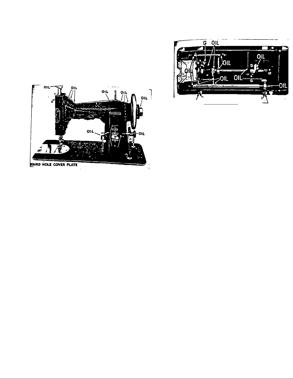
Oiling
A sewing machine, like every other piece of mach'
needs oiling to insure easy running and to prevent un
sary wear of the parts which bear upon each other.
Oil holes are provided in the arm of the machine for
which cannot be directly reached.
Depending on how frequently the machine is used d t»
mines the oiling requirements. Moderate use requires o \
occasional drop of oil at the points indicated on the"-n
trations shown. ®
To ofl the works underneath the bedplate, turn the 1
hack and apply oil to points as shown in Figure 2.
On automatic lift machines the thumb screw on the
late near the base of the arm must be taken out before
head can be turned back.
-HEAD HINGE SET SCREWS
-HEAP HINGE LUG HOLES-
FigTir» 2
Cleaning Machine
IF THE MACHINE RUNS HARD it is due to lack
proper oiling of some bearings. Should the machine beco
rammed from long standing or poor oil, apply kerosene to
the bearings to remove the gum; then run the machine ti
Idly, wipe clean and OIL THOROUGHLY WITH GOi
SEWING MACHINE OIL before beginning to sew.
Occasionally place one drop of oil on tip of finger i
apply around outer rim of shuttle, race, and center
(C.P.) fig- 6-
Fisrur* 1
Two
Be sure to use ONLY Eenmore Sewing Machine <
Three
Page 4
PRESSER BAR CAP
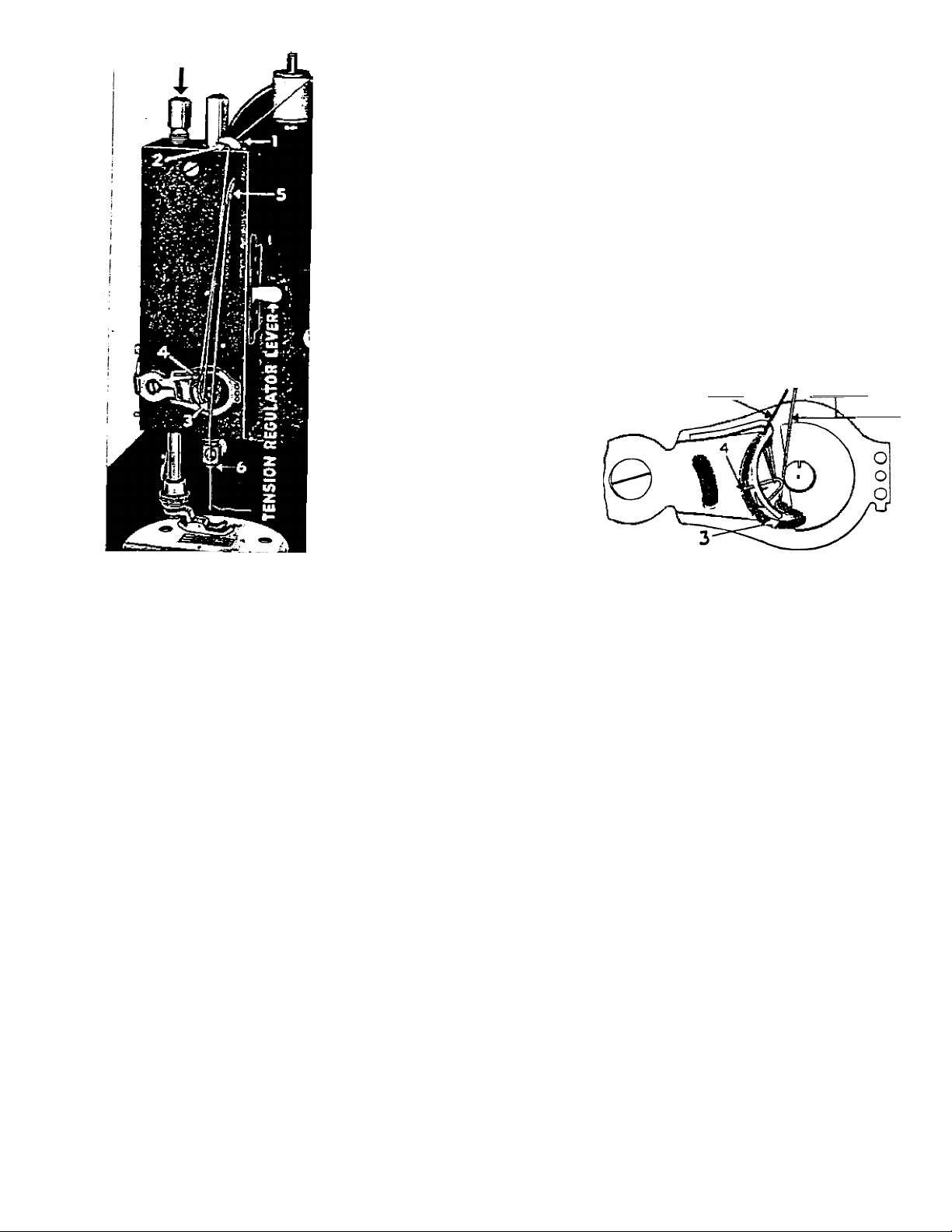
Threading
The Machine,
Upper Thread
(See Fig.
Your machine should h» •
proper position for thl.f- ®
by turning the hand !
(the top of the
from you) so that
up (5,.Fii 3) Tatit^ take.
est pomt., *ugh.
Place a spool of thread n
the spool pm on top^f
fhSnd Of the
thread in the left ®
tween the first fineer**
thumb, then use t^e
hand (first finger and thumbi
threat"^ "
Next, the thread should
pss under and in front of
hook one (1), then under aid
in back of hook two (2) “
Next, downward and hook
to bTck.°^"*
Next, pull the thread un
ward until it hooks into
spring eyelet No. 4.
Next, continue upward in
to the hole in the take-up
lever (5) from back to front
Next, downward and hook
thread into needle damn
thread guide 6 from back to
front. ,
Next, into the eye of needle
Figure 3 **i«vjA4*4c
(See enlarged view of tension assembly on page S)
from left to nght as you face
the machine.
Four
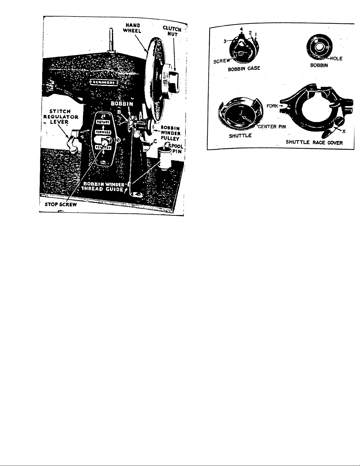
To Wind a Bobbin
(See Figure S Page 6)
, = the bobbin on bobbin winder spindle as sho’
tht hand wheel with the left hand and turn the top
Hold tne towards you. This will release the sew
th® of the machine. Next, place a spool of thr<
„lechanis located on bed of machine directly be!
on wheel. Next, take the end of the thread and p
the n^ the tension plates on bobbin winder thread gui
it b®two , j upward into eye of guide, then run end
fhfea'd through hole “B” in bobbin.
ir„,rocrp the bobbin-winder pulley with the hand wheel
k" O' lever “C” downward. Hold end of thread until y
pushing „chine sufficiently to wind the thread around i
boDDin machine and bobbin winder will automatica
contin proper amount of thread is wound. '
^^'^'iTfter the bobbin is wound and removed; tighten
?he hand ^h'eel with your left hand.
Five
several times: then break thread off at hole “B” a
. i k niit bv turning the top of it from you while holdi
‘ r>n non-electric machines proceed in the same mann
cept that power for operation is furnished by foot treat
TP *5
Enlarged view of tension assembly showing thread
ing of auxiliary spring, as described on page i.
FROM*I
AND*2
Page 5
nsoT* I
Six
F1*u« t
Threading the Bobbin Case
Hold bobbin case with thumb and first finger of lef
hand, with tension tongue (4) upright. Then place fillei
bobbin in case, starting thread into slot (1). Continue pull
ing thread up to end of slot (2); then across to bottom o:
slot (8) and upward until thread comes out at top of tensioi
tongue (4). Leave about two inches of thread projecting.
Caution —Note carefully the way the bobbin case ii
threaded before removing bobbin or unthreading.
Seven
Page 6
To Draw Up Lower Thread
While holding loosely in the left hand, the end of th
thread extending through eye of needle (three or fo„*
inches), turn the top of hand wheel from you (clockwUe\
with the right hand, until the needle goes all the way down
and comes hack up. The lower thread will form a loop over
the thread you are holding and come up through the needle
hole. Lead the ends of both threads back under the presser '
foot, keeping the upper thread in presser foot slot.
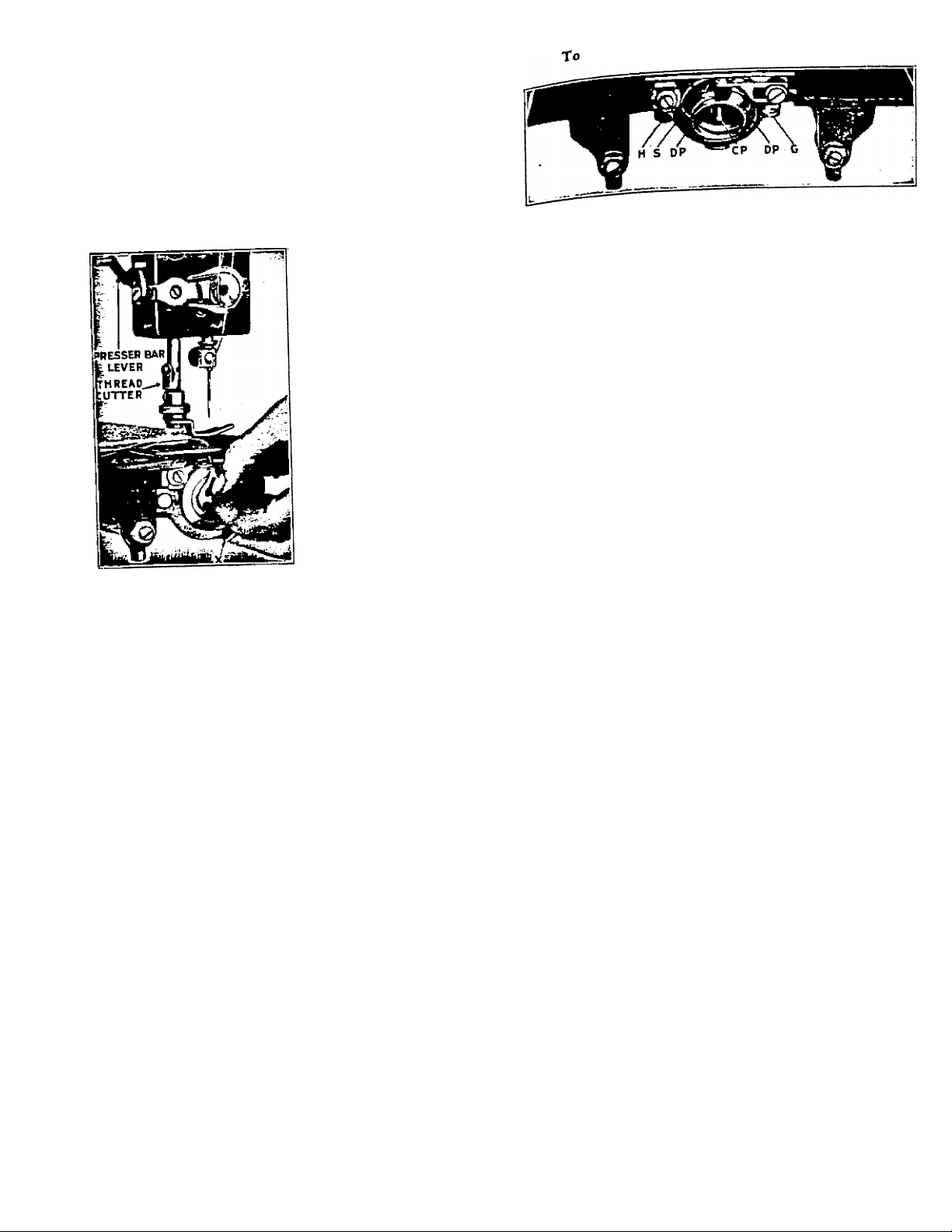
Remove Shuttle from the Shuttle Race
Flffur* 8
To Remove the Bobbin Case from Shuttle ’
Turn hand wheel (dock-
wise) until take-up (5^ pig
3) is at its highest point,
Then remove the hand hole
cover plate permitting you to
reach down to bobbin.
Clasp the bobbin case with
the thumb and first finger of
your left hand as shown in
Fig. 7. Then with the second
finger lift up on latch "X"
and the- bobbin case can be
readily removed.
Follow the same procedure
in replacing the bobbin case
in shuttle.
The hole in the center
spindle inside the bottom case
fits over the center pin of the
Usar« 1
shuttle, as shown in Fig. 6.
Eight
First remo ^ remove bobbin case as already ex
„move the hand hole cover plate and tip head
back on ite hi (clockwise) until the
plained. is just entering needle plate hole. Then .
point of the neM jp pig. g. This will release
press rear en readily removed
the shuttle ra the center pm m
from under p ^ readily removed WITH-
shuttlc (Cp/ '
OUT FORCE.
To Replace the Shuttle
m ... the hand wheel untU the point of the needle a just
entering the v shuttle by the center pin
■f*®;a!h other in the outer edge of the shuttle, are
oppMite each o^her pips (dP). When properly
lined up. the ou imperative that the
°i®L.n^L*nrooerly placed in the race, and it must never be
^,°®^!Sttìe rS cover by slipping the fork at left side
thè SHARP point of shuttle will be almost directiy
fnto^ position. When the shuttle is in position re-
the needle plate hole. With the thumb and first
entering tM n ^. ... the shuttle by the center pm
SS p“» (H) b.ck .«r Llpk (G)
whiS will snap back to its holding position.
Nine
Page 7

Regulating the Tensions
Upper:
When the presser foot lifter lever (Pig. 3) .
tension on the upper thread is automatically released
fore, the presser foot must always be lowered when ad‘
ing the upper tension. The tension regulator lever is f
on the face of machine (Fig. 3). To increase tension°'^*^^^
lever downward. To decrease tension push lever unJ*-
The most satisfactory tension for ordinary sewing is '
with pointer on this lever set between figures 2 and ^
numbered gauge.
Lower:
The small screw in center of the bobbin case (Pig B\
regulates the tension on the lower thread. To increase ten
sion tighten the screw; to decrease tension, loosen it. in
either event only turn this screw a little bit at a time.
Tension should be in balance to get best results
fiexible, accurate stitching. Experiment until your stitching
is balanced as follows: ■
If the upper thread is too tight, the upper thread will be
drawn straight on the top of the material, thus:
If the lower thread is too tight, the lower thread will be
drawn straight on the bottom of the material, thus:
When tensions are properly adjusted the stitching on
materials will look the same on both aides, thus:
________
neat
Ten
To Regulate Stitch Length
(Forward and Backward With Stops)
mu stitch regulator lever (Fig. 5, page 6) controls th
’J’116 . ,_onrl woirciwcii
’itengTfor both forward and" reverse:
st’mhi positioning of the stop screw (Fig. 5, page 6) regi
he
^length of the stitch, forward and reverse, by li
lates the down of the stitch regulator level
i„g the mu _ T
8PP.f ¿omes to rest.
“"a long as the stop screw is not turned the length o
lengtn gjj j.jjg stop screw and set the stitch regulator U
®u Hpsired longer stitch as shown in the window in the plat«
mh ” same longer stitch will now result both forward and
revise, except that number 4 is the longest reverse stitch
length. .
hpfore attempting to remove the work. Failure to do this will
° in breaking the thread and unthreading the needle.
ffc highest point, raise the presser foot with presser foot lever
snd DRAW THE FABRIC BACK about three inches in a
straight line, pass both threads over the thread cutter on the
nresser bar. After the material has been removed and the
threads cut, do not run the machine accidentally or other
wise without material under the presser foot. (See following
in the window then turn the stop screw to the righ
. u will remain the same.
T sew in reverse, move the lever down until it stops.
1° sew forward, move the lever up again until it stops.
Tf the lever and stop have been set for a short stitcl
th such as No. 2, and the operator wishes to use a longei
titrhten the stop screw as before until it comes to rest
The take-up (5, Fig. 3) must be at its HIGHEST POINT
Turn the hand wheel until the take-up (5, Pig. 3) is at
To Set the Stitch Length:
^jje stitch regulator lever until the desired nunibe
To Remove the Work
__
-----
^L.
limil
paragraph.)
IMPORTANT—When the machine is threaded, do not
operate it without having material
under the presser foot.
Failure to observe this instruction will cause thread to
lodge in the shuttle mechanism and prevent machine from
Eleven
Page 8

running properly. To correct, take out bobbin case and run
the machine in the wrong direction, turning wheel by hand
and it will cut thread out; or better still remove shuttle and
clean the race and driving pins.
To Avoid Breaking^ Needles
Never pull the work, causing needle to strike the needle
plate. A needle may also be broken by sewing heavy seams
oT* very thiclc goods without sufficient pressuie on the presser
foot for such heavy work. To increase this pressure, turn the
thumb screw on top of the presser bar.
To Set the Needle
The needle bar should be raised to its highest point.
Loosen the thumu screw of the needle clamp and press it to
the left This will permit the shank of the needle to pass up
Kofween the clamp and the needle bar as far as it will go
tfth the flat side of the the
needle clamp screw securely. Use a screw driver.
tL needle when descending should pass in the center
of the needle plate hole from front to rear, but close to
right side of needle hole. If it does not the needle is either
bent or improperly set
Proper Needles and Thread
It is important to use perfect needles that are not bent
nor blunted! When ordering needles for this machine men
the name and give the head number. For ordinary fam-
S sewing!”se needle size No. 1. This will carry thread No.
60 to No. 90.
Needle Sizes
0
For plastic film, use No. 0 needle and mercerized thread.
Needle and Thread Sizes
Cotton Thread
80 to 100
60 to 80
40 to 60
30 to 40
Heavy Duty Mercerized
Heavy Duty Mercerized
Other Threads
Mercerized
Nylon A
Silk A
Mercerized
Mercerized
Twelve
The Narrow Hemmer
ilfure »
. ■ h«« ever equaled the dainty finishing that it h
Nothing h« ever Narrow Hemmer.
iTofaifd^ifdes" ^ to"tor"n “Stcia^tr
row hem m Serial in Hemmer crease over % incl
Before i"®®’^^^"f;^nce of about 2 inches, insert edge ii
of its edge for a ^he scroll, folded edge on top
Hemmer guiding .. jg under needle; lower presse
draw to stitch. Should stitching appear too far fror
bar and begin push Hemmer slightly toward the right
turned edf too close to edge, or not catching a
iriovi toward th. Lit.
Guide and uneven hems; neither too little, nc
iLwing^for"l second turning, thus leaving a raw edge. Th
tcroTl Xuld be kept just full.
Thirteen
foyial so that neither too much feeds into th
Page 9

Hemming and Sewing on Lace in One Operation
With the Foot Hemmer
. Figxm 10
The Narrow Hemmer is designed with a slot at the right
into which the edge of lace, rick-rack braid or any finished
edge can be inserted and stitched to garment while it is being
hemmed.
Proceed to make a hem in the same manner described on
previous page. Insert edge of lace or trimming right side
down in slot at right of hemmer and see that the needle
pierces it close to the edge Just above turned edge of hem.
Commence to stitch guiding the lace edge into the slot of
hemmer with the right hand while guiding material to be
hemmed into the scroll of Hemmer with the left hand.
Applying lace in what is termed the French manner also
requires the use of the Narrow Hemmer. Enter the fabric to
be hemmed as for plain hemming, enter laces from the left,
right side down, on top of the fabric; allow edge of lace to
enter hemmer and meet material just as it is being turned,
thus the hem will enclose lace edge in one stitching. Press
hem back on wrong side of fabric and no visible stitching
will mar this dainty finish.
■ Fourteen
A FcU.d S.a» F““'
Fleur« 11
A felled seam is generally used where double strength
J with a nice flat finish.
th. mo pioooo of to b. .»».d t^.tb
Place the t J section to extend about
with righ other Place goods under the Foot Hemm
inch beyond th presser foot, keeping narrow si
Just as though hemmer
of seam “PP®™ ’ After stitching is completed op
“ goWe 'ruCtndIr foof hemmer with right side of ma
seams end p machine and the widest half of sei
^dThe right. This widest portion of seams edge is tk
toward the r g of hemmer (See Fig. 11) and if seam 1
entered ^ ^he % inch or widest half of seam v
S.-” d ot» ¿0 A look >” •
Fifteen
Page 10

Wide Hemmen
Cutting Gauge
biarSnL
a binding: or narrow
for y®®ither straight or bxas to
bands f*"®facings, pipings,
' FipJ« U
An assortment of wide hemmers is furnished with
Sewing Machine.
Attach the desired size of Hemmer to machine in place
of the presser foot; crease over 14 inch of material to be
hemmed for about two inches before inserting edge of goods
Enter material and guide it around scroll of hemmer using
both hands to draw it back and forth a few times, while
gradually feeding the cloth into the hemmer so as to fill the
scroll completely. Draw material back so that creased edge
fits around edge of scroll in hemmer and selvedge edges meet
Hold both under and upper threads and proceed to stitch. '
Should the stitching appear too far from turned edge of
hem loosen thumb screw and move hemmer toward the right.
If it appears dangerously close to turned edge of hem move
hemmer toward the left.
As material is stitched through the large hemmers the
turn at edge of hem is visible. Allow the hem to ride freely
through the hemmer, never drawing on the edge being turned,
but gently retarding the material under the hemmer, using
the left hand.
your
Sixteen
The inch and fractions thereof, d
ienated on the cutting gauge, enab.
one to cut material of any te.\ture pi
fectly for use with the binder.
%linch of hi-inch is correct for firn
woven nriaterials.
1-inch to IV*-inch IS correct for rx
terials that stretch more readily. T
gauge slide is adjustable and can
moved to the left or right. -
Figure 15
Attach cuttingsg^an^ove
gauge siiqe material
• “ in he used with the
bin%r be cut on a
evenly.
Seventeen
slide to width of band
betwLn the blades
if toportant that bind-
Figure 14
Fleur* IS
Page 11

The Multiple Slot Binder
The popidariiy ior bindings that do double dntv «
dinnnishea. Bindings are frequently used to finish
of fabric as well as furnishing a garment’s onW ®
-- , Th. MulUpl. Slot bM “ST
irAbV.ri SX““#?
making of dainty garrmfr,*
caU for narrow binding wln^thl
SfSSL"' “> \
each designed to carry binding oi
their width. Size 1-2-3-4-B. ^ ”
Commercial single fold bindine
must U used and fed into th!
slots of same size as illustrated
The familmr % inch or H inch
bias cut binding which every
t^nough the open mouth of the
The Binder is adjustable side
Fisur. 17 erly close to the edge of binding
wise to bring the stitching pron-
SstLl; ^
« entered
Exclusive Bindings with the
Multiple Slot Binder ^
Remove the presser foot, attach Binder in its place. «
As shown in Fig. 18 the Multiple Slot Binder can be used S
for attractive combination trimmings so much in vogue on
jabots and frilled accessories.
Our illustration shows a tricolored trim using com
mercial single fold bindings sizes 1—3 and B. Sizes 5 and 3
act as two tone pipings while size 1 binds the edge enclosing
the fabric in the double piping all in one single stitching.
This trimming is just as effective on the reverse side of fabric
making it a desirable accomplishment for any dainty cascade.
Eighteen
Fisur» 18
riin bindings to a decided point and enter each width
•t respective slot helping it beyond the needle with the i
f a large needle or pin and starting with the narrow,
•dth The edge to be bound is inserted in the center of i
¡l^chment between the scroll and held in as far as possil
without crowding.
Manv lovely double binding combinations are possible
sevCTal different sizes; 1 and 3; 2 and 4; or 3 and 6.
Binding with Bias Cut Binding
Binding that has been cut and prepared for Bind
should be cut to a long point, inserted into the scrolls
Binder and helped forward beyond the needle by the aid of
large pin. Lower presser bar and stitch to ascertain whe
stitching line appears on binding.
.Nineteen
Page 12

Fignr# 19
The Binder is adjustable and can be moved to left or
right, until line of stitching appears safely close to edge of
binding.
In binding scallops it is necessary to hold the edge to be
bound well into the fold between scroll of Binder as fabric
nears the needle, at this point only is binding being stitched
and if care is exercised no stretch will appear on this curved
edge. Illustration of bound scallops (Fig. 19) clearly shows
this operation.
Additional rows of binding can be applied as a trimming
by placing garment to be trimmed under the Binder and guid
ing the spaces between rows by thé edge of Binder Frame.
Twenty
Quilting
Figvre 20
much depends upon the accuracy in stitching espe<
V. ^ =i?rcessive rows are used for trimming. The quiltei
^.t"as aTawurate guide for any stitching that is sj
»V, than the presser foot allows.
'^’'^For“ genuine quilting over wadding the Quilter C
i the Ouilter Foot has no equal. Place as i
liicknlsSsli wadding over the wrong side ^
thicknesses u cheese cloth over the who
as P pucker so desirable on comfortables or q
the 5i?ead cutter screw at back of presser
Free tne quilter wire to fit into the screw
®A'!r‘^lt”ouilter Guide the distance from needle desired
wh enough from bed of machine so that material can
high en B . gjj tighten screw.
“”‘^let tte machine stitch fairly long and keep the w
®*^For exteemSv^thkk'padding release the pre^ure on
Quifter Foot by turning the Pre.«ser Bar Cap. (Fig. 3).
Twenty-one
Page 13

RufBer
A. Slots to space
fullness at number
of stitches.
B. Slide lever to
regulate depth oi
pleat.
Attach Kuffler by Pjf
the foot “C” on |ttachment
holder and the ®
astride the needle clamp
screw. •
See that needle goes do\ro
in center of needle hole in
Ruffler.
Ruffling
Enter material to
between blue blades.
material is guided into ”
“everal slots or adjustable
guides provided for different
widths of seam allowance or
headings, as shown in these
pictures.
At point “A”, set pin in No.
1 opening for f^the| at every
stitch. At point B loosen
screw and set lever
gather. No. 1 makes the finest
father. Length of stitch
ing machine varies amount of
fullness.
Pleating can be pleats, spaced cJ
At P°'”p„ing for pleat
№• ® °fixth ftitch. At
every s'i, loosen screw,
point 15 fiown to deepen
fength of stitch on sewing
machine.
Ko"^M opentog
every „ loosen screw,
Prifp lever down to deepen
slide lever ce pi^^tg by
fenfto of stitch on sewing
machine.
Rhoff P^Sied" to make first group of pleats. Stop sewi
^ At point “A” set pin in
ftoi. Stitch without plea^
pre'rillsVeatingposttiom
Twenty-two fuoenty-three
V #„™ed in a wide range of effects. '
Six-Stitch Pleating
“A” set pin in
Twelve-Stitch Pleating
“A” set pin in
twelfth stitch. At
Group Pleating
C ' V 1I^^:
Rix-stitch or twelve-stitch pleating,
Page 14

Shirring
The Shirring Plate is used to
make wide ruffles, deep headings
on ruffles, and for continuous rows
of shirring.
To Use Shirring Plate:
1 Remove handhole cover. Put Shirring Plate on machine
0 Remove lower blade and heading guide by loosening
3. Put Ruffler on machine as before.
4. Set attachment
Doint “YY” in screw hole of needle plate. Point
eoes in squared opening of needle plate, and is held
in'place with handhole cover, replaced at this point.
fmSl screw on right side of Ruffler. and slipping for
ward. Tighten small screw.
for ruffling. For
several rows of
shirring, it helps
to use the Quilt
ing Guide for
spacing.
Piping »nd Edgestitching to Ruffle
Shirring Plate. Enter material to 1
Use Huffier right. Guide into seam-allowan<
ruffled be^een piping through
slot of Shirring ^ fabric. Guide folded edg
on left- Fold "tnd above blades. To adjust the guu
into slot above pipi 8 screw behind needle ho
needle sews on veijf
Twenty-four
Twenty-five
Page 15

Combinatioo Edge-Stitcher, Tucking Guide and
Top-Braider
The Edge-Stitching Attachment is
fastened to the machine in the same
manner as the Presser-Foot. There are
five different slots, which are shown in
the illustration, serving as guides for
sewing together laces, insertions, em
broideries, sewing in position folded or
hemmed edges, bias-folded material or
piping, etc.
How to Adjust the Edge-Stitcher
To adjust, move the lug “A” ^he right or Mt until the
desired adjustment is obtained. When semng two pieces of
lacf together, it is very necessaij that the a^chment is
adjusted to stitch exactly on the edge, so that the edges will
not fold over when laundered.
When sewing laces or soft materials together, it is “®tter
to hold the edges, slightly overlapped, This will prevent the
lace from feeding away from the guide. ^
When the attachment is properly adjusted, the most inexnerienced operator may sew yards of lace or material
tolether with no difficulty.
Tucking
The numbers 2 to 6 inclusive stamped on the back edge
of the sliding guide represent the width of tuck in eighths
of an inch. After folding the material for the first tuck, put
the folded edge into the guide slot which is nearest the needle.
When the left edge of the friction spring “H” coincides with
the number 2 on the scale a tuck results
In like manner, set the guide at 3 for ® tuck.
In like manner, set the guide at 4 for a % tuck.
In like manner, set the guide at 5 for a %" tuck.
In like manner, set the guide at 6 for a tuck.
For tucks narrower than U" move the guide "G” as far
as desired to the left.
fwenty~$ix
■ Braidmg
Move the 8^ . . with the needle hole of the atts
hole “K” »s fifiM^to be braided should be plainly mar^d
«ent. The right side of the fabric. Start
stamped hole “K” and stitch along desi^, be
soutache feeding freely into hole
sure that turn a comer, stop the machine v
without twisting. TO gjjggt comer of
the preswr-bar just enough to permit the to
design, the p^ the desired direction, lower the press
“G” to the right until the braiding gr
bar^nd proceed as before.
Twenty-seven
Page 16

The Shirring Foot
Figure 26
One of the very newest and well liked Se^ng Machine
triiSfngf i thelinty smocking obtained when nsxng the
^“Mr2rshows rows of shirring held firmly by a row of
Fig. 26 snows . hole of Shirnng Foot
and “ I shirring are broken by a diagonal shirring
Th^rX: atSTttractive puffing for a smocked effect
The Shirring Foot replaces the presser-foot for this work
and ihe amoUt of fullness obtainable is ^he
^ * machine stitch and tension. For fine shirring set
riu'rA.” iuita- >.»»«■» “•
and tighten the upper tension. •
cJeMly C.U. i.b* » ,i‘ >»"=
material feeds to the needle singly.
Twenty-exgKt
Tk. Combi»»““ Adjos“bk Zippor
A«»»bi»s »»d Coodms Foot
This attachment is designed s<
can be adjusted for stitching eii
left or right side of cording in a s
or for stitching right or left
when attaching a slide fastener,
just by loosening thumb screw-
sliding foot to desired position on
Inserting Cording
FlfUM II
■Remove the re^iar p place. Loosen the tl
Mb Combination move the foot to the rig
iilw on the attachment and move ^t^^^
S;%ordinj is^ >%^uttr%f the needle hole before tig
,i=c Tiresser foot and attach the Ad
fnltL^thumb. screw
Fold a strip of bias q+itch along close to the
place under Adjustable Attachment b|mg u»
Fig. 2] ®^Hoin it to a fabric edge in one atitehing
Bar^djusting Cap Screw^.^E^^^^^ Combination Attachi
more freely unuc»
Twenty-nine
Page 17

Attaching a SUde Fastener
. Fifure 28
Remove the regular presser foot and attach the Com*
bination Attachment in its place. Loosen the thumb screw
on the attachment and move the foot to the right or left as
desired. See that the needle goes down in center of the
needle hole before tightening the thumb screw.
The needle holes on either side are cut deep enough to
allow sufficient space between the metal of tiie slide fastener
and the line of stitching so the fabric wiU not catch in the
slide pull as it is being opened and closed.
Fig. 28 shows a slide fastener being stitched in a gar
ment with the Combination Adjustable Zipper Attaching and
Cording Foot positioned to the right of the needle.
Thirty
To InstaU Sewing Machine Head on Cabinet
°f-jt\ead binge
and 2)
‘“®.\ound shanks
°Tthl two hinges
attached to^ of cab-
■'"It Tip head back
to back of
tighten head
set screws
(Fig® 2) securely.
^to^iS'ariea?
r°the motor as pos-
a?d slip motor
cord into slot at edge
f bed plate and
nush bushing back
fnto hole in bed p|a j ^
(see Fig. 9); y“ ^ord inside the cabinet, plug into an
wind the ef^f"®*and the machine is ready for operation,
base plug ' trehdle operated, merely place leather bel
“ Thind wheel drive pulley as of course there is no moto
^electrical connections. _ .
Motor Lubrication
/rtTic at either end of the motor shaft) provid
Two ““Purgation. Unscrew the caps and fill with petro
occasionally, depending upon the use of the ma
chine ^Sproximateiy every six months.
’ Speed Control and Current
„.v .loeired sewing speed is obtained by pressing th^
The pressure from the knee lever auto
knee lever. Rem g ^e used on eithe
Tr or DC, no on IIB volts up to 75 cycles.
^ Motor Pulley
Ra sure the motor pulley (Fig. 9) is adjusted so i1
centers on the disc wheel of the machine.
Thirty-one
Page 18

SIMPLE CORRECTIONS FOR
MINOR DIFFICULTIES
This sewing machine was carefully adjusted and tested
before being delivered, and with proper care and attention
according to the directions in this book should give you no
trouble. To be sure of getting the proper supplies for it, such
as needles, oil and bobbins we recommend that you buy them
from us, always giving the name of your machine and its
serial number.
If your machine should actually need replacernent parts
or repair service we suggest that you get in touch with us.
Do not permit just anybody who comes along to tamper with
or attempt to fix your machine. Unskilled agents and un
trained repair men often do far more harm than good in
attempting to adjust a sewing machine.
For the most part sewing machine troubles can be reme
died by minor adjustments easy to perform. Should your
machine start misbehaving, check over the following list of
minor difficulties and simple corr_ections for them, before
calling for help.
If It Skips Stitches
The trouble may be caused by— ■
1. Crooked Needle: i ■ ■
May be hardly perceptible yet sufficient to cause skipping.
Unthread the needle, remove presser foot, turn machine
bv hand. Needle should maintain a constant position in
relation to the needle hole as the needle passes down
through the needle plate hole. ■ .i,- •
Replace with a new needle and make certain this is not
the cause of trouble.
2. Incorrect Needle—or too fine a needle: „
It is very important that you have the correct needle. Be
certain to follow the table in this instruction book in
selecting the proper size needle for size of thread and
material being used. .
3. Needle incorrectly set: . .
The needle must be pushed up as far as it will go into
the needle clamp with the flat side of the shank to the
right and fastened securely with thumb screw.
Thirty-two
w pdle rubs Presser Foot:
^ . „.-»«.ipr foot holder on the presser bar so th:
Adjust pres «r cubbing, the right side of tV
needle i® „rake this adjustment, loosen the sma
presser to presser foot holder to presser ba
screw rna proper position and finuly tightc
sMlVf the foot.
jf It Breaks Thread
The trouble may be caused by—
■a7w,ntr Needle being used: _
1^/fs Important before trying anything else to put in i
new straight ■tieedle, proper kind and size.
table elsewhere in this instruction book.
, pr-ie in the Needle Plate Choked with Stray Threads:
P 11 threads from the tcnderside of needle plate witl
screw driver or long needle, or better remove plate anc
clean. , . .
A Machine Improperly Threaded:
rheck over carefully the instructions on threading the
«^arhine and observe especially the threading of the
Sieck spring on top of the face plate.
Refe^to'1n°s*tr^tionf elsewhere in this book on the proper
adjustment—both upper and lower tensions.
R Needle too Close to Presser Foot:
Adjust foot as described “Needle Rubs on Presser Foot”
under “Skips Stitches",
7 Examine needle hole in needle plate. If it has become
' rough or burred from needle striking it, needle plate
should be replaced with a new one.
If It Breaks Needles
The trouble may be caused by—
1 Pulling of the material when sewing will break needles.
Guide the material only—do not pull.
Thirty-three
The Se should be a trifle closer to the rigb
the proper needle and thread according to thi
Page 19

' '-i
---■i
%
-'
■
2. Wrong Needle being used: ,
Be sure you are using the correct needle for this machine.
3. Needle incorrectly set—too low:
- See instructions elsewhere in this book on how to prop,
erly set needle and follow instructions carefully.
Needle Rubs on Presser Foot:
4.
Adjust foot as described “Needle rubs on Presser Foot"
under “Skips Stitches”.
Needle not firmly set:
5.
After being certain needle is properly set be sure it is
held tight by needle clamp screw—use a screw driver.
If Puckers On Ordinary Material
The trouble may be caused by—
1. Tensions NOT in balance:
Reduce the'tension on upper thread by- moving indicator
towards No. 1. Do some testing. If this fails, examine
lower tension on bobbin case for proper adjustment and
proceed to balance the tensions. See instructions else
where in this book on tension adjustment.
Blunt Needle—Replace with a new straight needle—ex
2.
amine needle point.
1/
The trouble may be caused by—
Both tensions may be too tight: ^
1.
Adjust upper and lower tensions—must be in balance.
For chiffon and other very light materials, best results
are obtained with upper tension set at % and the lower
tension in balance with that. However, sufficient tension
must be maintained to raise the small auxiliary spring
(No. 4 in Fig. 3) when machine is in operation.
Presser foot loose in holder:
2.
Tighten knurled thumb screw.
Blunt Needle:
3.
Replace with new straight needle—examine needle point.
Thirty-four
Needle Plate:
1, in this plate might be slightly bent down. N.
hole might be rough from needle striking it
eifhir «.se a new needle plate is required.
Loose Stitching
The trouble may be caused by—
Tension too loose—either top, bottom or both:
1.
gee instruction.-» elsewhere on tension adjustment
balance.
Upper Tension fails to Operate Satisfactorily:
2.
T int or stray threads lodged between tension plate Nc
n ¡L the presser foot lifter (see illustration). Set
fension regulator at figure No. 1, next cut a piece of 1
down a few times which will remove any bits of thread i
lint from between tension plate No. 1 and washer No.
Thirty-five
_ cloth to a point and di
this strip of cloth thrm
and under tension pi
No. 1 and close to sci
No. 3 on the side from »
as shown in illustrati
This cloth should be dra
down through tension ph
No. 1 and washer No. 2 i
shown in illustration), t
can be accomplished
holding tension plate (T
1) and washer (No.
apart with a small sen
driver. Be careful to dri
the cloth between pis
No. 1 and washer No.
When you have this do
in place, drop the press
bar lifter, move the te
sion regulator toward N
8 and pull the cloth up ai
Page 20

 Loading...