

Page 1

MODEL ACC-31
6-DISC CD CHANGER WITH
WIRED COMMANDER
COMPACT
DIGITAL AUDIO
INSTALLATION MANUAL
Page 2
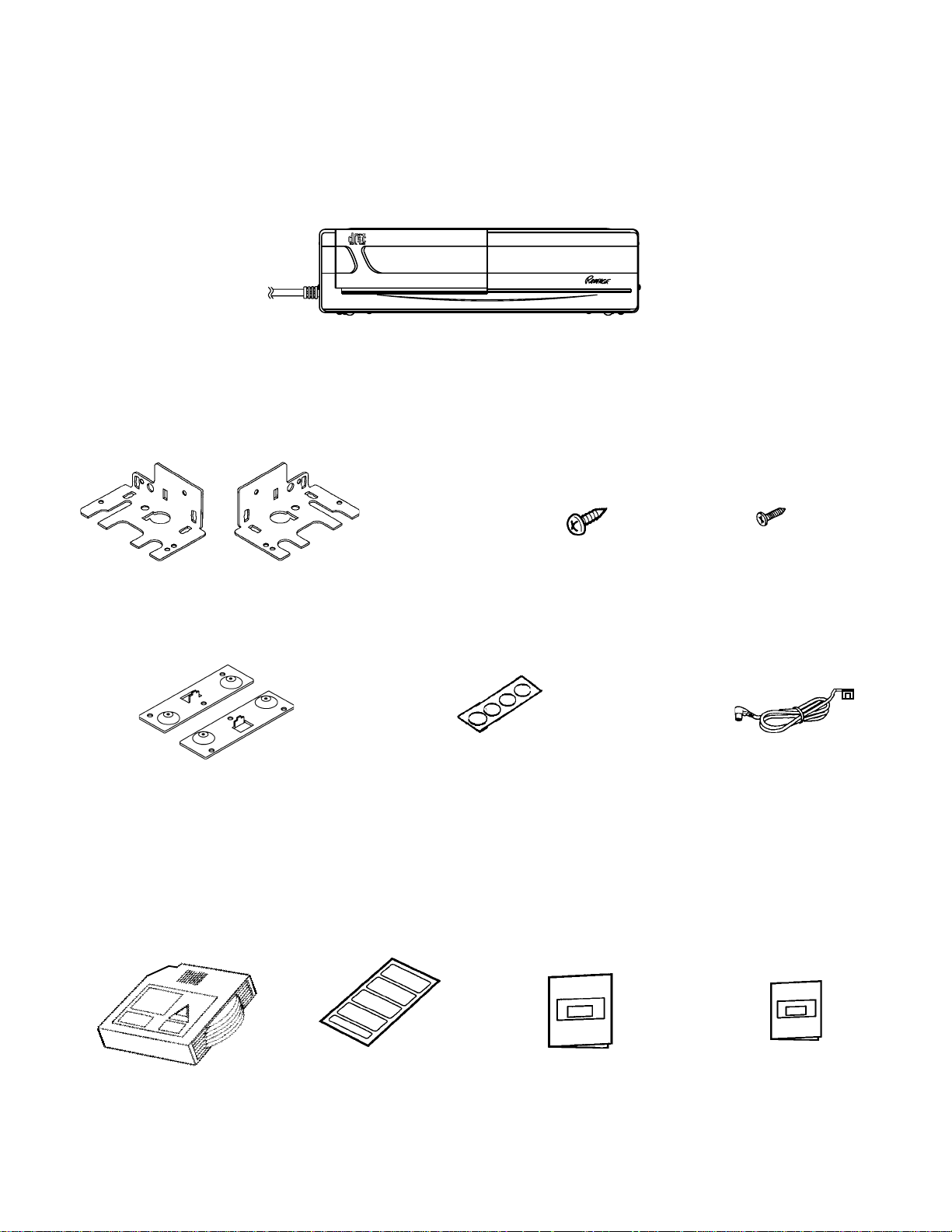
PACKING LIST
MAIN UNIT
INSTALLATION PARTS
CD Changer
ACC31
DIGITAL AUDIO 6 DISC
COMPACT DISC CHANGER
BY AUDIOVOX
Changer Mounting Brackets
L
1 each
Floor Mounting Brackets
LR
1 each
ACCESSORIES
R
Self-tapping screw
(M5 x 12),
w/Lockwashers
6 pcs. each
Screw Hole Cover Labels
1 pc.
Phillips Hex -Head
Bolt (Small), w/Flat
Washers and Lockwashers
8 pcs. each
5 Meter Din Cable
1 pc.
CD Magazine
P/N:ACC31MAZ
1 pc.
Index seal sheet
1 pc.
Installation Manual
1 pc.
Owner's guide
1 pc.
2
Page 3
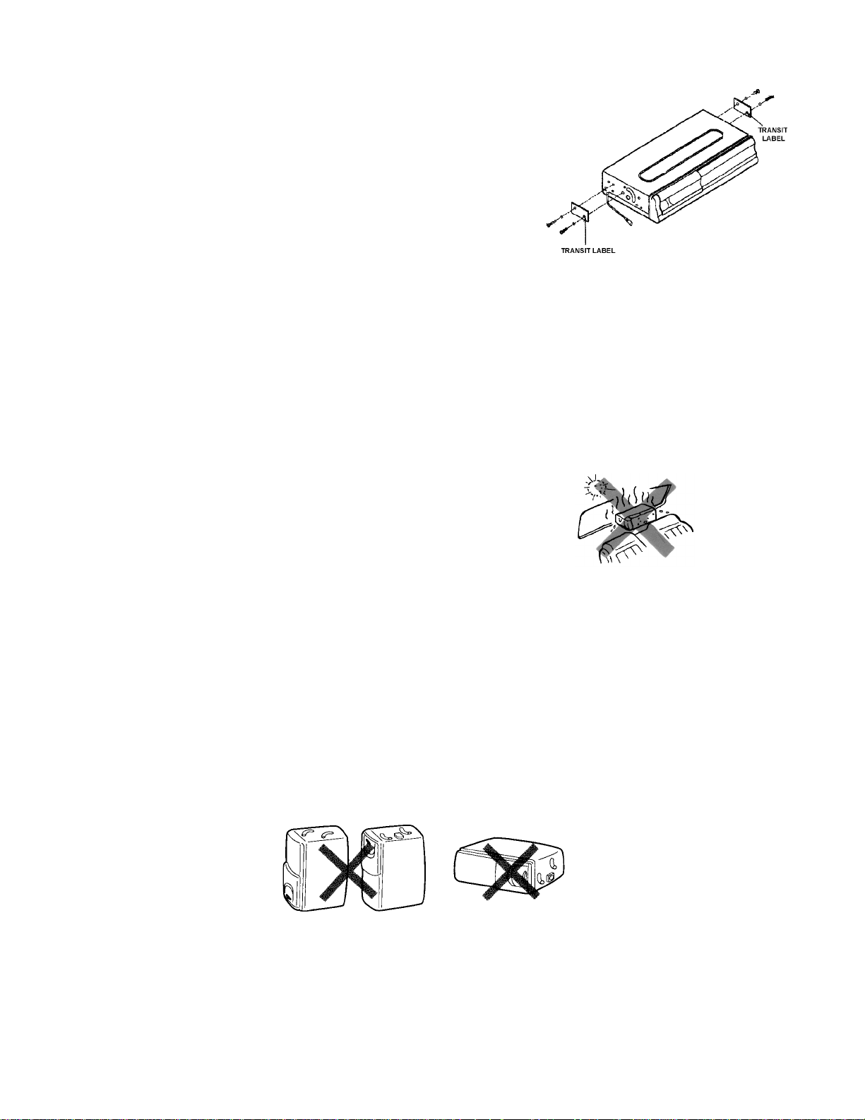
BEFORE INSTALLING THE UNIT
Transport Lock Screws
The mechanism in the CD changer is "locked" into place during
shipment by the 4 transport screws, two on each side. Be sure to remove
the screws prior to installation. Retain these screws for future use when
transporting the unit for service/maintenance.
CAUTION
After removing the transport lock screws, place the supplied seals over
the screw holes. These seals are used to keep dust out of the unit, which
could cause a malfunction.
Installation and Wiring Precautions
To prevent a short-circuit,
1
l Be sure to turn off the ignition and remove the negative (-) battery cable, prior to installation.
l Connect power wires last.
NOTE
If the changer is to be installed in a car that is equipped with an on-board drive or navigation computer, do not disconnect
the battery cable. If the cable is disconnected, the computer memory may be lost. Under these conditions, use extra caution
during installation not to cause a short circuit.
Do not install the unit in the following locations:
2
l Locations exposed to direct sunlight.
l Where hot air is discharged from the car heater.
l In areas subject to extreme temperatures.
Incorrect installation can cause the CD Changer sound to "skip" when playing
3
a disc. Mount the unit firmly in place, using the supplied brackets and screws.
Be careful not to damage the car wiring.
4
l Be sure to use the supplied screws.
5
l Be careful not to snag any wires when tightening screws.
l Do not use any of the screws that are part of the brake or steering system to install the unit.
l This unit cannot be installed on its side, end, or upside down. Installation in such positions will cause malfunctioning
6
of the mechanism.
3
Page 4

INSTALLATION
C
O
M
P
A
C
T
D
I
S
C
C
H
A
N
G
E
R
D
I
G
I
T
A
L
A
U
D
I
O
6
D
I
S
C
A
C
C
3
1
BY AUDIOVOX
The unit can be installed horizontally (position H), or vertically at a 90° angle (position V). The position of the built-in anti-vibration
springs (left and right side), must correspond to the mounting position chosen. If the springs are not set correctly for the type of
installation chosen, the anti-vibration compensation will not be effective and vibration may cause the disc to skip.
HORIZONTAL INSTALLATION
Set the anti-vibration springs to
position "H".
POSITION
"H"
POSITION
"V"
VERTICAL INSTALLAITON
Set the anti-vibration springs to
position "V".
PROCEDURE FOR HORIZONTAL INSTALLATION
1
Attach a mounting bracket to each side of the unit, using the
hex head bolts and washers.
NOTE: Make sure anti-vibration springs
are set to position "H" as shown
above.
Hex head bolts
and washers
Bracket
Determine the mounting location and drill two mounting holes.
2
NOTE:If mounting surface is carpeted, use caution
when drilling holes to prevent drill bit from
catching on carpet. Cut holes in carpet
before drilling into sub-surface.
WARNING
Never mount the unit near the fuel tank.
Secure the unit in place, using two self-tapping Phillips head
3
screws.
Use RTV (silicone sealer) on screw threads or around
the holes to prevent moisture intrusion.
Carpet
Drill holes 1/8" (4mm) in diameter.
Self-tapping Phillips head screw
A
C
C
3
1
D
I
G
I
T
A
L
C
A
O
U
M
D
P
I
O
A
C
6
T
D
D
I
S
I
S
C
C
C
H
A
N
G
E
R
BY AUDIOVOX
Bracket
4
Bracket
Page 5

PROCEDURE FOR VERTICAL INSTALLATION
Note
If the anti-vibration spring position has been changed and verified for vertical mounting (as shown on page 4), start with step 2.
Set the anti-vibration springs to position "V"
1
as shown below .
POSITION
"V"
Attach a mounting bracket to each side of the unit, using
2
the hex head bolts and washers.
Bracket
Bracket
Hex head bolt
and washer
Determine the mounting location and drill two mounting holes.
3
NOTE:If mounting surface is carpeted, use caution
when drilling holes to prevent drill bit from
catching on carpet. Cut holes in carpet
before drilling into sub-surface.
WARNING
Never mount the unit near the fuel tank.
Carpet
Drill holes 1/8" (4mm) in diameter.
Mount the unit in place, using two self-tapping Phillips head
4
screws.
Use RTV (silicone sealer) on screw threads or around
the holes to prevent moisture intrusion.
Self-tapping
Phillips head
screw
Bracket
Hex head bolt
and washer
Bracket
5
Page 6

VEHICLE COMPONENT LA Y OUT
NOTE: 1. Check with your Rampage/Audiovox audio dealer to
be sure your stereo is directly compatible with
this CD changer.
2. When used with Rampage Model AV-427 car
stereo, be sure Changer Selector switch on bottom
of radio chassis is set to position "B".
6
Page 7

© 2000 Audiovox Electronics Corporation,
Happauge, N.Y. 11788 Printed in China
8
128-5943
 Loading...