

Singer 591 Service Manual
SINGER
591
Service
Manual
CONTENTS
Page
DESCRIPTIONOFMACHINE
ADJUSTMENTS
To Set
Needle
Barat Correct Height 2
To Set
Check
Spring
Height
2 —3
To Set CheckSpringTension 3
To Set PresserBarat Correct Height 4
To Time the SewingHook and also Set the SewingHook Sidewise in Relation to the Needle 5
Feed
To
Reverse
Time
the
Lever
Feed
To Set Feed Dogat Correct Height 7
Needle
REMOVAL
To remove
To Replace Oil Filter
To Replace
BarFrame
AND
the
Sewing
the
Sewing
Driving
REPLACEMENT
Linkage
Hook
143042
Hook
Adjustments 22 —23
OF
PRINCIPAL
ASSEMBLIES
To Remove and Replace the Hook Shaft 10
The Oil Pump 11
To Remove and Replace the Upright Arm Shaft 12 —13
To Remove
and
Replace
the
Needle Bar 13
To Remove and Replace the Presser Bar 14
Needle Thread Take-up . . . 14 —16
To Remove and Replace Arm Side Shield Wick, Needle Bar Wickand Needle Bar Connecting
Stud
To
To
The
Wick on
Remove
Install
Arm
Shaft
Oil Wick
New
Oil
Drop
Feed Machines 16
Holder
Wick
Holder
17—18
18
The Bobbin Winder 22
1
6
6
8
9
9
17
—21
SERVICE
Needle
INSTRUCTIONS
BarFrame
Driving
FOR
Linkage
COMPOUND
FEED
SYSTEM
Adjustments 23
To Remove and Replace Arm Side Shield Wick,Needle Bar Wickand Needle Bar Connecting
Stud
Wick
To
To
Remove
Remove
on Compound Feed
and
and
Replace
Replace
Needle
Compound
Machines
BarFrame
Feed
★
A
Trademark
Copyright
All
Rights
Assembly
Connecting
of
©
1981
Reserved
and
Needle
Bar 25
Rod 25
THE
SINGER
THE
SINGER
Throughout
COMPANY
COMPANY
the
World
24
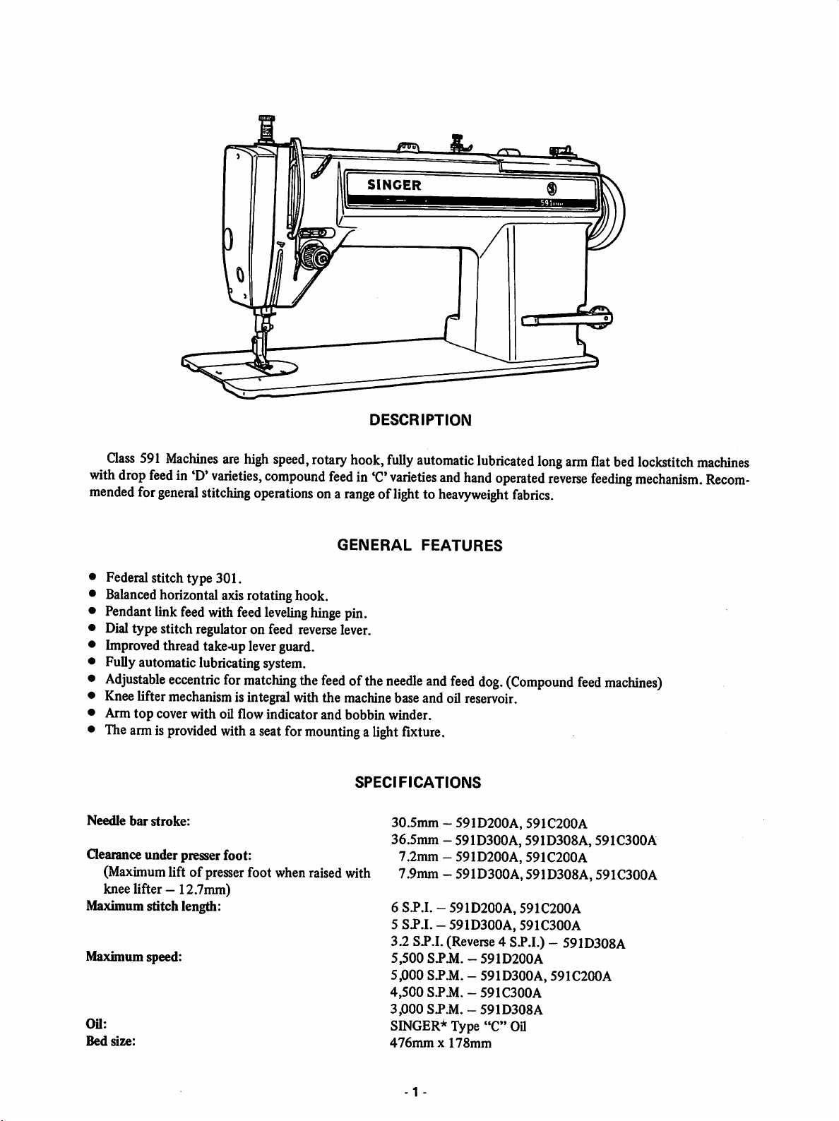
Class
with
drop
mended
591
feed
for
Machines
in'D'
general
are
varieties,
stitching
high
speed,
compound
operations
SINGER
DESCRIPTION
rotary
hook,
fully
automatic
feed
in'C
varieties
ona
rangeoflighttoheavyweight
^9^
and
lubricated
hand
operated
long
fabrics.
arm
reverse
flat
bed
feeding
lockstitch
machines
mechanism.
Recom
GENERAL
Federal stitch type 301,
Balanced
Pendantlinkfeedwith feed
Dialtype stitch regulator on feed
Improvedthread take-upleverguard.
Fully automatic lubricatingsystem.
Adjustable
Kneelifter mechanism isintegral with the machinebaseand oil reservoir.
Arm
The
Needle
Oearance under presser foot:
(Maximum liftofpresserfoot when raisedwith
knee lifter —12.7mm)
Maximum stitch length:
Maximum speed:
Oil:
Bed
size:
horizontal axis rotating hook.
leveling
eccentric
top
cover with oil flow indicator and bobbin winder.
armis
provided
bar
stroke:
for
matching
with
aseatfor
hinge
pin.
reverse
the
feedofthe
lever.
mountingalight
SPECIFICATIONS
FEATURES
needle
and
feed
fixture.
30.5mm-591D200A,
36.5mm - 591D300A, 591D308A, 591C300A
7.2mm
7.9mm
6 S.P.I. -
5
3.2 SP.I. (Reverse4 SP.I.) - 591D308A
5,500
5,000
4,500
3,000
SINGER* Type
476mmx178mm
- 591D200A,
- 591D3G0A,591D308A, 591C300A
591D200A,
SJ.I.
- 591D300A, 591C300A
SPA1.-591D200A
SP.M.
S.PJd.-591C300A
SP.M.-591D308A
dog.
(Compound
591C200A
591C200A
591C200A
- 591D300A, 591C200A
"C"
OU
feed
machines)
-1
-
TO
SET
NEEDLE
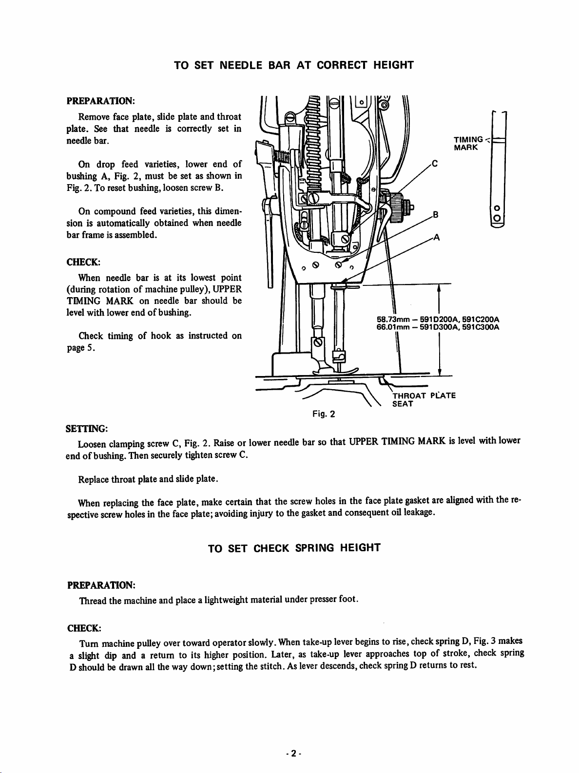
PREPARATION:
Removeface plate, slide plate and throat
plate. See that needle is correctly set in
needle
bar.
BAR
AT
CORRECT
HEIGHT
TIMING
MARK
On drop feed varieties, lower end
bushing A, Fig. 2, must be set as shown in
Fig, 2. To reset bushing, loosen screw B.
On compound feed varieties, this dimen
sion is automatically obtained when needle
bar
frameisassembled.
CHECK:
When needle bar is at its lowest point
(during rotationofmachine pulley), UPPER
TIMING
level
page 5.
SETTING:
end of
MARK
with
lower
Check timingofhook as instructed on
Loosen
clamping
bushing.
on
needle
endofbushing.
bar
should
screwC,Fig.2.Raiseorlower
Then
securely
tighten
of
be
screw
C.
needle
Fig. 2
barsothat
58.73mm-591D200A,
66.01mm-591D300A,
UPPER
TIMING
THROAT
SEAT
MARKislevel
PLATE
591C200A
591C300A
with
lower
Replace
When
spective
PREPARATION:
Threadthe
CHECK:
Turn
a
slight
Dshouldbe
throat plateand slideplate.
replacing
screw
machine
dip
the
face
plate,
holesinthe
machine
pulley
face
and
placealightweight
over
toward
andareturntoits
drawn
allthe waydown;settingthe stitch.As
make
plate;
higher
certain
avoiding
TO
SET
operator
position.
that
the
injurytothe
CHECK
material
slowly.
under
When
Later,astake-up
-2
screw
gasket
SPRING
presser
take-up
lever
holesinthe
and
consequent
HEIGHT
foot.
lever
beginstorise,
lever
descends,
face
plate
oil
leakage.
approaches
checkspringDreturns to rest.
gasket
are
aligned
check
springD,Fig.3makes
topofstroke,
with
check
the
spring
re
SETTING:
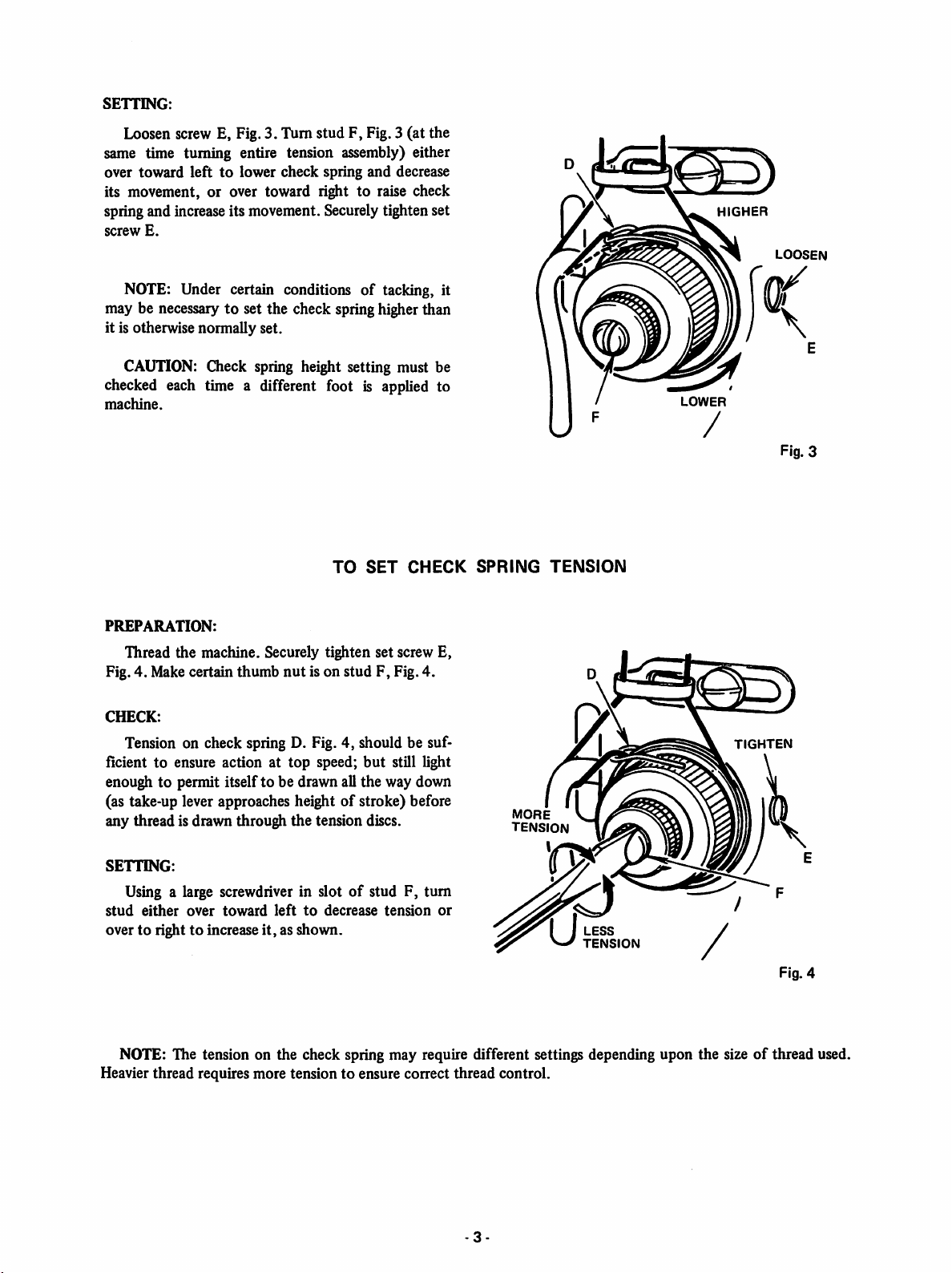
Loosen screw E, Fig. 3. Turn stud F, Fig.3 (at the
same time turning entire tension assembly) either
over toward lefttolower check spring and decrease
its movement,
or
over toward righttoraise check
springand increaseits movement. Securelytighten set
screw
E.
NOTE: Under certain conditions of tacking, it
may be necessary to set the check springhigherthan
it is otherwise normally set.
H
GHER
LOOSEN
CAUTIGN:
Check spring height setting must be
checked each time a different foot is applied to
machine.
TO
SET
CHECK
PREPARATION:
Thread the machine. Securely tighten set screw E,
nut
Fig. 4. Make certain thumb
CHECK:
is on stud F, Fig. 4.
Tension on check spring D. Fig. 4, should be suf
ficient to ensure action at top speed;
but
still light
enough to permit itself to be drawn all the way down
(as take-up lever approaches height of stroke) before
any thread is drawn through
the
tension discs.
SPRING
MORE
tension
LOWER
Fig. 3
TENSION
TIGHTEN
SETTING:
Using a large screwdriver in slotofstud F, turn
stud
either
over
toward
over to righttoincrease
lefttodecrease
it,
as shown.
tension
or
LESS
TENSION
NOTE: The tension on the check spring may require different settings depending upon the sizeofthread used.
Heavier thread requires more tension to ensure correct thread control.
-3
Fig. 4
TO
SET
PRESSER
S)
(9
BAR
CLEARANCE
FOOT
RESTING
FIRMLY
UPON
THROAT
PLATE
AT
CORRECT
AT
HIGHEST
POINT
HEIGHT
<S)
Si
AT
LOWEST
POINT
JUST
✓
CLEAR
I
I
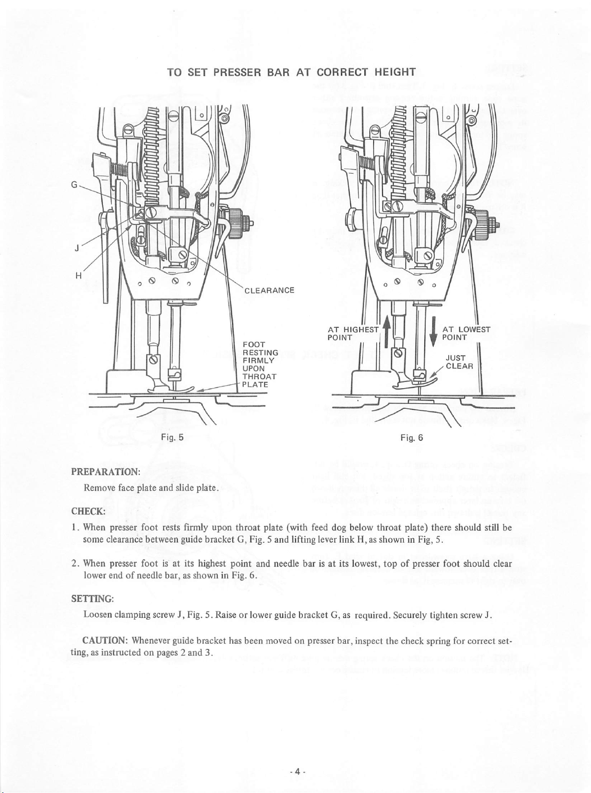
PREPARATION:
Remove face plate and slide plate.
CHECK:
1. When presser foot rests firmly upon throat plate (with feed dog below throat plate) there should still be
some clearance between guide bracket G, Fig. 5 and lifting lever link H, as shown in Fig, 5.
2. When presser foot is at its highest point and needle bar is at its lowest,
of
lower end
SETTING:
needle bar, as shown in Fig. 6.
topofpresser foot should clear
LoosenclampingscrewJ, Fig. 5. Raiseor lower guide bracket G, as required. Securely tighten screwJ.
CAUTION:
ting, as instructed on pages 2
Whenever
guidebracket has been moved on presserbar, inspect the check spring for correct set
and
3.
TO
TIME
SEWING
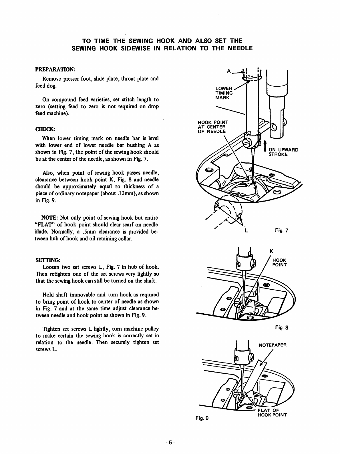
PREPARATION:
HOOK
THE
SIDEWISE
SEWING
Remove presser foot, slide plate, throat plate and
feed dog.
On compound feed varieties, set stitch length
zero (setting feed to zero is not required on drop
feed machine).
CHECK:
When lower timing mark on needle bar is level
with lower endoflower needle bar bushing A as
shown in Fig. 7, the pointofthe sewing
be at
the
centerofthe
needle, as shown in Fig. 7.
hook
should
Also, when pointofsewing hook passes needle,
clearance between
should be approximately equal to thickness
hook
point K, Fig. 8 and needle
of
pieceofordinary notepaper (about .13mm), as shown
in Fig. 9.
HOOK
IN
RELATION
to
a
AND
ALSO
TO
HOOK
AT
OF
SET
THE
LOWER
TIMING
MARK
POINT
CENTER
NEEDLE
THE
NEEDLE
ON
UPWARD
STROKE
NOTE: Not only pointofsewing hook
"FLAT"ofhook
point
should clear scarf on needle
but
entire
blade. Normally, a .5mm clearance is provided be
of
hook
tween hub
SETTING:
Loosen two set screws L, Fig. 7 in
and oil retaining collar.
hubofhook.
Then retighten oneofthe set screws very lightly so
that the sewinghook can still be turned on the shaft.
Hold shaft immovable and turn
hook
as required
to bring pointofhook to center of needle as shown
in Fig. 7 and at the same time adjust clearance be
tween needle and
hook
point as shown in Fig. 9.
Tighten set screws L lightly, turn machine pulley
to
make certain the sewing
relation
screws
to
the
needle.
L.
hook
is correctly set in
Then
securely tighten set
Fig. 7
HOOK
POINT
Fig. 8
NOTEPAPER
Fig. 9
FLAT
HOOK
OF
POINT
FEED
REVERSE
LEVER
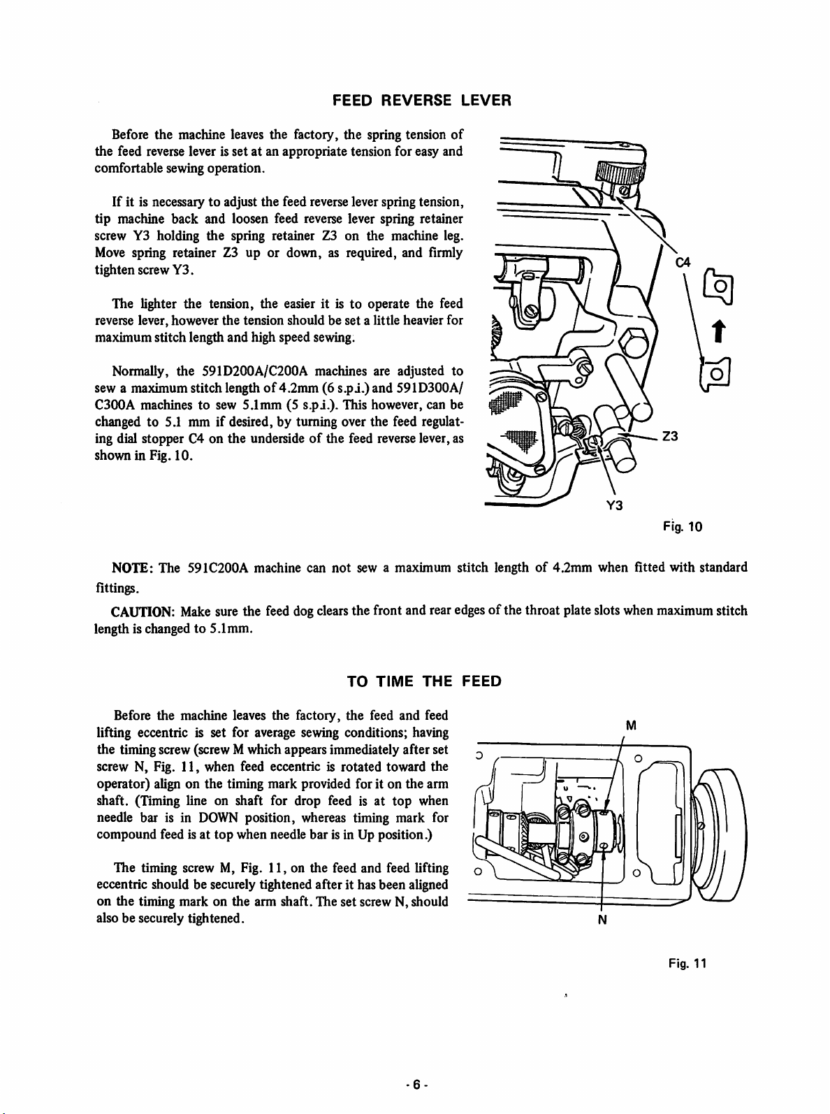
Before the machine leaves the factory, the spring tension
the feed reverse lever is set at an appropriate tension for easy and
comfortable sewing operation.
If it is necessary to adjust the feed reverse lever spring tension,
tip machine back and loosen feed reverse lever spring retainer
screw Y3 holding the spring retainer Z3 on the machine leg.
Move
spring retainer Z3 up or down, as required, and firmly
tighten screw
The lighter the tension, the easier it is to operate the feed
reverse lever, however
maximum stitch length and high speed sewing.
Y3.
the
tension should be
set
a little heavier for
of
Normally, the 591D200A/C200A machines are adjusted to
sew a maximumstitch lengthof4.2mm (6 s.pi.)and 591D300A/
C300A machines to sew 5.1mm (5
changed to 5.1 mm
ing dial stopper C4 on the underside
shown in Fig. 10.
if
desired, by turning over the feed regulat
s.pi.).
This however, can be
of
the feed reverse lever, as
0
Fig.
10
NOTE: The 591C200A machine can
fittings.
CAUTION:
length is changed to 5.1mm.
Before
Makesure the feed dogclearsthe front and rear edgesof the throat plate slots when maximumstitch
the
machine leaves the factory,
not
sew a maximum stitch lengthof4.2mm when fitted with standard
TO
the
TIME
feed
and
THE
feed
lifting eccentric is set for average sewing conditions; having
the timingscrew (screw M which appears immediately after set
screw N, Fig. 11, when feed eccentric is rotated toward the
operator) align on the timing mark provided for it on the arm
shaft. (Timing line on shaft for drop feed is at
needle bar is in
compound feed is at top when needle bar is in Up position.)
The timing screw M, Fig. 11, on the feed and feed lifting
eccentric should be securely tightened after it has been aligned
on the timing mark on the arm shaft. The set screw N, should
also be securely tightened.
DOWN
position, whereas timing mark for
top
when
FEED
Fig. 11
-6-

If for any reason, it is necessary to alter the timing of feed and feed lifting eccentric, the eccentric should be
adjusted and locked in desired setting with the timing screw Mand the set screw N.
NOTE: Whenever the timingofthe feed is changed, sewing hook should be checked for necessary adjustment
also as instructed on page 5.
TO
SET
FEED
DOG
AT
CORRECT
HEIGHT
FULL DEPTH OF TEETH
I
0.8mm
- 591D200A, 591C200A THROAT PLATE
1.0mm-591D300A, 591D308A,
t'
Fig. 12
When the feed dog is at its highest position, approximately the
full depth of all the teeth should project abovethe top surfaceof the
throat plate, as shown in Fig. 12.
Before checking the heightofthe feed dog, set the machine for
the longest stitch.
To adjust, loosen the clamping screw P, Fig. 13 and raise or lower
the feed dog (which is fastened to the feed bar Q, Fig. 13) as re
quired. Then securely tighten screw P.
The feed dog should be level at the top
its feed path.Ifnot,
tip machine back and
loosen feed bar hinge pin clamping screw A4
just enough to
tum
feed bar hinge pin (ec
centric) B4, Fig. 13. Insert screwdriver into
access hole in end
as required to level the feed dog. Securely
of
bed and
tum
hinge pin B4
tighten clamping screw A4. Check feed dog
height.
If it is found necessary to adjust the feed
dog height due to the material being sewn
and/or exchanging the feed dog and throat
plate, it should be adjusted in the manner ex
plained above.
of
HIGHER
m
LOWER
591C300A
Fig.
.
13
NOTE: Feed dog should
centrally in relationtothe front, rear and sidesofthroat plate slots.
not
contact edgesofthe throat plate slots during its movement
-7-
but
should be located
 Loading...