

Page 1
Instruction
Manual
and
Parts List
High Speed Straight
Lockstitch Sewing Machine
® Singer
191D
~
is
a registered trademark
© 2009
SINGER
of
The Si
nger
Company Limited
Copyright
The Si
nger
Company Limited
20!20C
30/30C
70/
70C
"
or
its
aff
iliated companies.
Page 2
Contents
1 Safety
1.1
Important
1.2 Safe Operation
2 Product Description and Machine Specification
2.1
Product Description
2.2 Machine Specification
2.3
Motor,
Setup and
3
3.1
Table Cut-
3.2 Oil Reservoir Installation
3.3 Belt Cover
3.4 Lubrication
3.5 Thread Take-up Lever
3.6 Rotating
3.7 Needle
3.8
Bobbin
3.9 Machine
3.10 Stitch Length
3.11
Thread Tension
3.12 ThreadTake-Up
3.13 Knee Lifter
3.14 Presser Foot Lifter
3.15 Presser Foot Pressure
3.16
FeedTiming
3.17 Feed Dog
3.18 Needle
3.19 Presser Bar
3.20 Thread Take4 Maintenance
4.1
Machine Head Cleaning
4.2 Lubrication
Safety Inspection
4.3
5
Troubleshooting
Instructions
Safety
Motor
Adjustment
Out
and
Hook
Attachment
Case
Threading
Height
to
Rotating Hook Relation
Instructions
Pulley
Drawing
Attachment
Adjustment
Height
Adjustment
Height
Up
and
Bobbin
Oil
Supply
Adjustment
Spring
Adjustment
Adjustment
Adjustment
Adjustment
Stroke
V-Belt Specifications
Instructions
Winder
Oil
Supply
Adjustment
Adjustment
Adjustment
Installation
Adjustment
Adjustment
Adjustment
1
1
2
3
3
4
4
5
5
6
7
8
8
9
10
11
11
12
12
13
14
14
15
16
17
18
19
20
21
21
21
21
22
Page 3
Contents
6 Parts List
6.1 Frame
6.2
Arm
6.3 Needle Bar,
Components
6.4 Presser Foot
6.5 Feed Mechanism
6.6
Lubr
6.7 Oil Reservoir
6.8 Belt Cover,
6.9 Machine Accessories
and
Cover
Shaft andThreadTake-
ication
Bobbin
Components
Upright
Components
Components
Components
Components
Winder
Up
Lever
Components
Shaft and Rotating Hook
and
Thread Stand
Driving
Components
Shaft
23
24
26
28
30
32
34
36
38
40
Page 4
Safety Instructions
1.1
Important Safety
Instructions
Important
When using the
machine, basic safety
procedures
be followed.
with attention all
instructions before
using the machine.
When using
understand that
all basic safety
instructions are
not
limited to the
following items.
Read all instructions,
take care
manual, and use
as
reference when
must
Read
1t,
of
this
necessary.
it
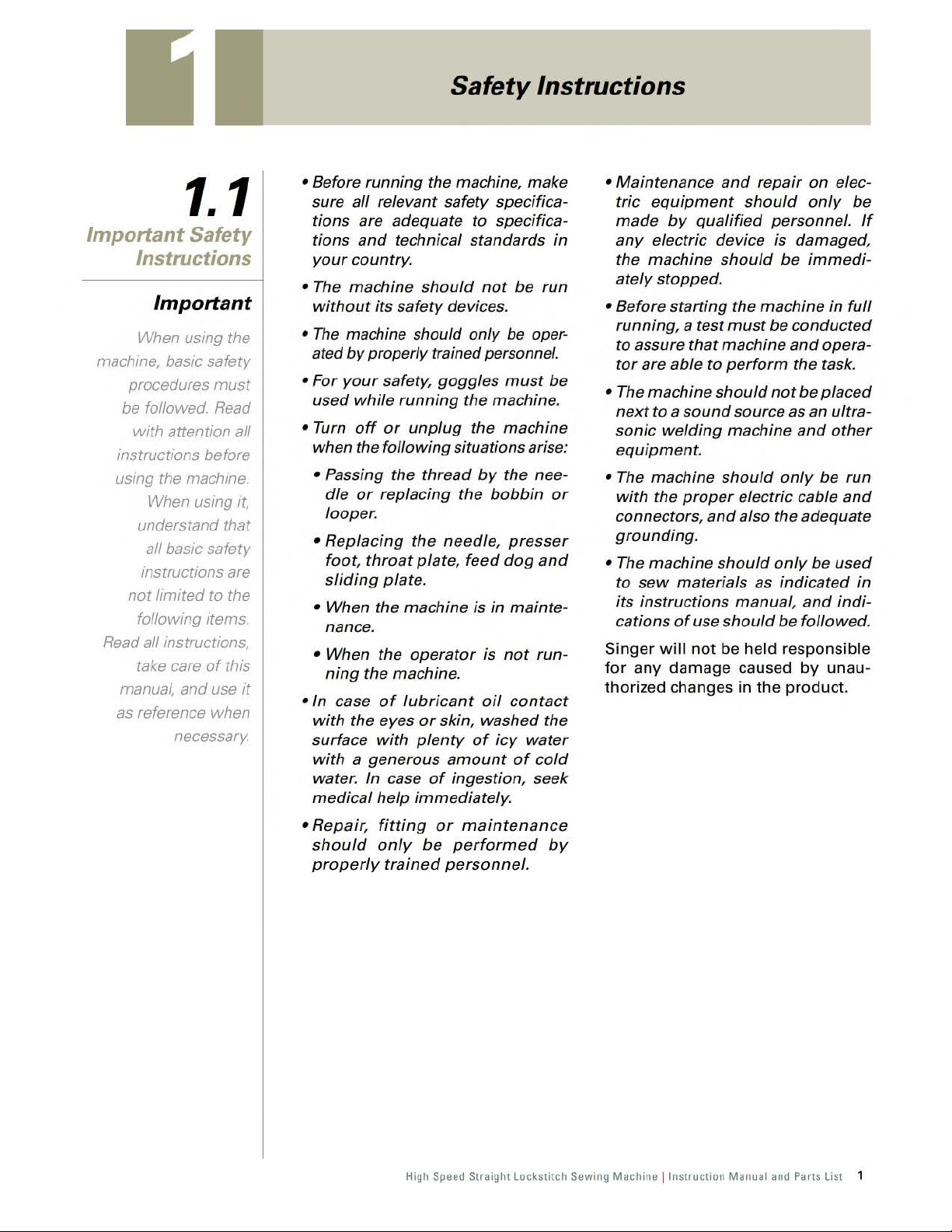
• Before running the machine, make
all
sure
tions are adequate
tions
your
• The machine
without
•
The
ated
• For
used
• Turn
when the
• Passing
dle
looper.
•
Replacing
foot,
sliding
• When the machine is in
nance.
• When the
ning
•In
with
surface
with
water. In case
medical
relevant safety specifica-
to
and
technical standards
country.
should
its
safety
machine should only
by
properly trained personnel.
your
safety,
while
running
off
or
unplug
following
the
thread
or
replacing the
the
throat
the machine.
case
the eyes
a generous
plate,
plate.
operator
of
lubricant
or
with
plenty
of
help
immediately.
not
devices.
goggles
the machine.
the machine
situations arise:
by
needle,
feed
is
oil
skin, washed the
of
amount
ingestion, seek
specifica-
be
run
be
oper-
must
the nee-
bobbin
presser
dog
and
mainte-
not
run-
contact
icy
water
of
cold
in
be
or
• Maintenance
equipment
tric
made
any
the machine
ately
• Before starting the machine
running, a test
to assure
tor
• The machine
next
sonic
equipment.
• The machine
with
connectors,
grounding.
• The machine
to
its instructions manual,
cations
Singer
for
thorized changes
by
electric device is damaged,
stopped.
are
able
to a sound
welding
the
sew
of
will
any
damage
and
repair
should
qualified
should
must
that
machine
to
perform
should
source as an ultra-
machine
should
proper
materials as indicated
not
electric cable
and
also the adequate
should
use
should
be held responsible
caused
in
the
on
only
personnel.
be
immedi-
be
conducted
and
the task.
not
be
and
only
only
be
and
be followed.
by
product.
elec-
be
If
in
full
opera-
placed
other
be
run
and
used
in
indi-
unau-
• Repair,
should
properly
fitting
only
trained
or
maintenance
be
performed
personnel.
High Speed Straight Lockstitch Sewing Mach ine !
by
Instruct
ion Man ual and Parts List 1
Page 5
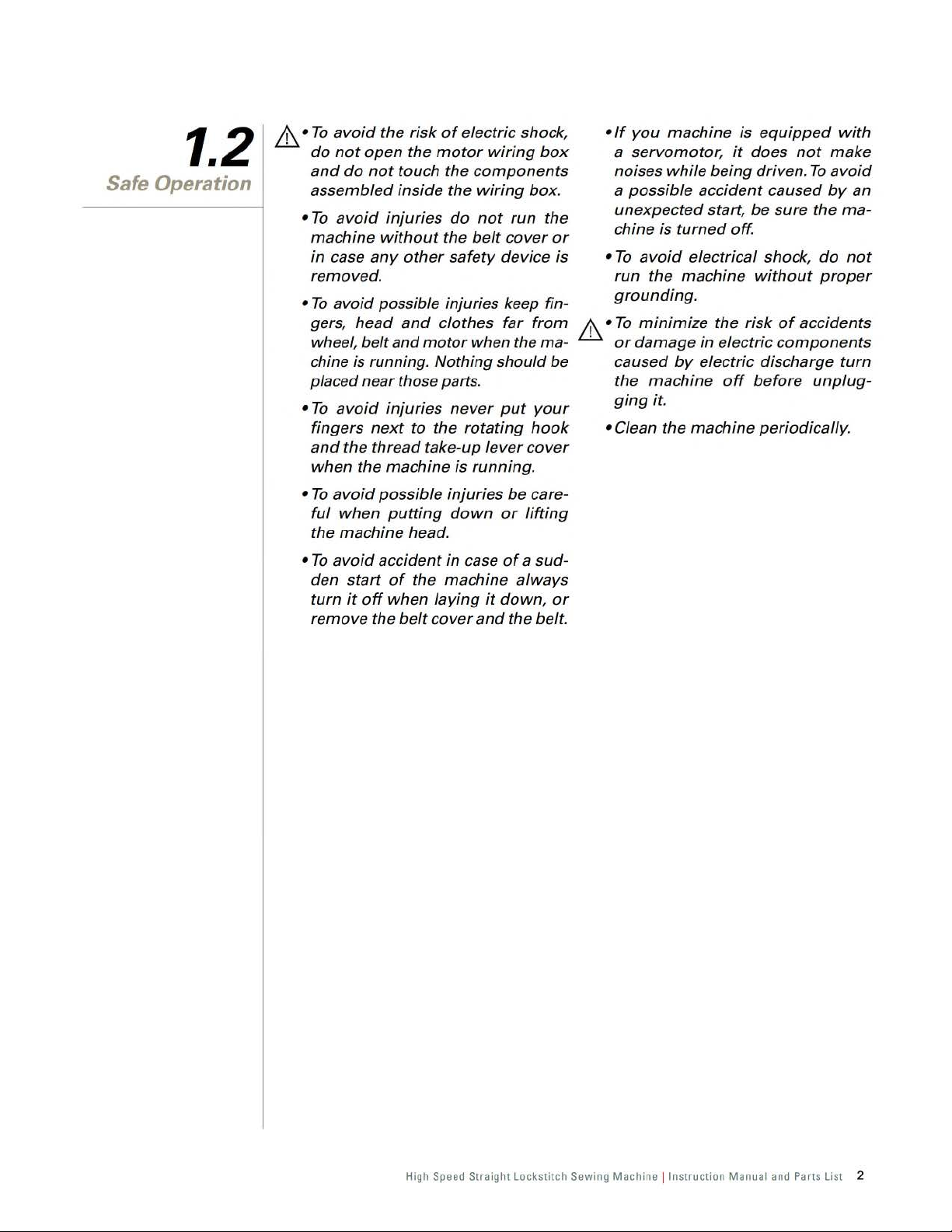
1.2
Safe Operation
.&_
•
To
avoid
the risk
do
not
open
and
do
not
assembled
•
To
avoid
machine
in
case
removed.
•
To
avoid possible injuries keep fingers,
wheel, belt and
chine is running. Nothing should be
placed near those parts.
•
To
avoid
fingers
and
when
•
To
avoid
ful
when
the machine head.
•
To
avoid
den
turn
remove the
injuries
without
any
head
injuries never
next
the
thread
the
machine is running.
possible injuries
putting
accident
start
of
it
off
when
of
electric shock,
the
motor
touch the
inside
other
and
motor
to
take-up
the machine always
belt
components
the
do
the
belt
safety
clothes
when the ma-
the
rotating
down
in
case
laying
cover
and
wiring
not
lever
it
wiring
box.
run
cover
device is
far
from
put
hook
cover
be
care-
or
lifting
of
a sud-
down,
the belt.
box
the
or
your
or
•
If
you
machine is
a servomotor,
noises while being driven.
a possible accident caused
unexpected start,
chine is
•
To
run the machine
grounding.
.&_
•
To
·
or
caused
the machine
ging
• Clean
turned
avoid
minimize
damage
by
it.
the
it
off.
electrical shock,
the
in
electric
electric discharge
off
machine periodically.
equipped
does
not
be
sure
without
risk
of
accidents
components
before
with
make
To
avoid
by
an
the
ma-
do
not
proper
turn
unplug-
High Speed Straight Lockstitch Sewing
Machine !Instruction
Manual and Parts List 2
Page 6
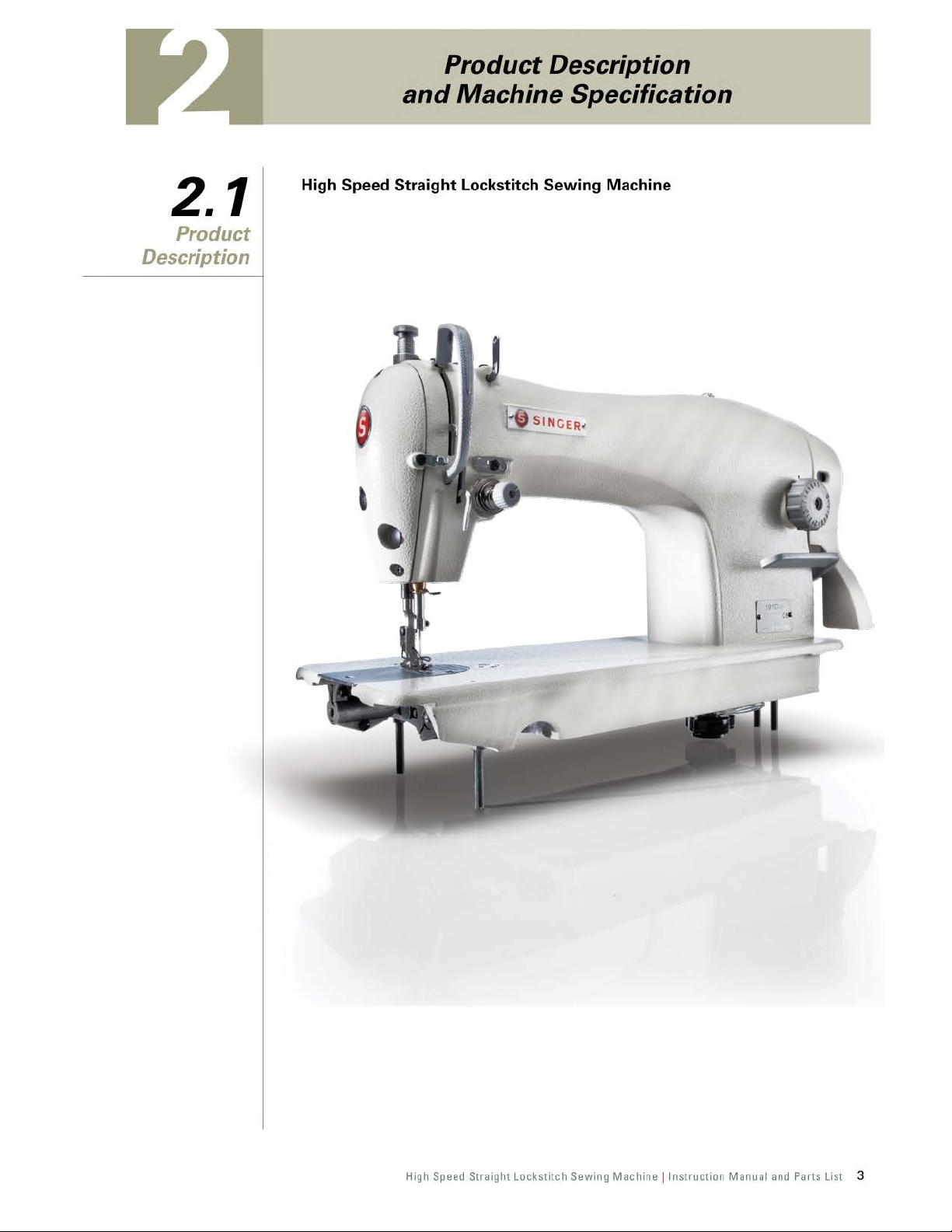
Product Description
2.1
Product
Description
and
High Speed Straight Lockstitch Sewing Machine
Machine Specification
c
High Speed Straight
Lockstitch
Sewing
Machine !Instruction
Manual and Parts List 3
Page 7
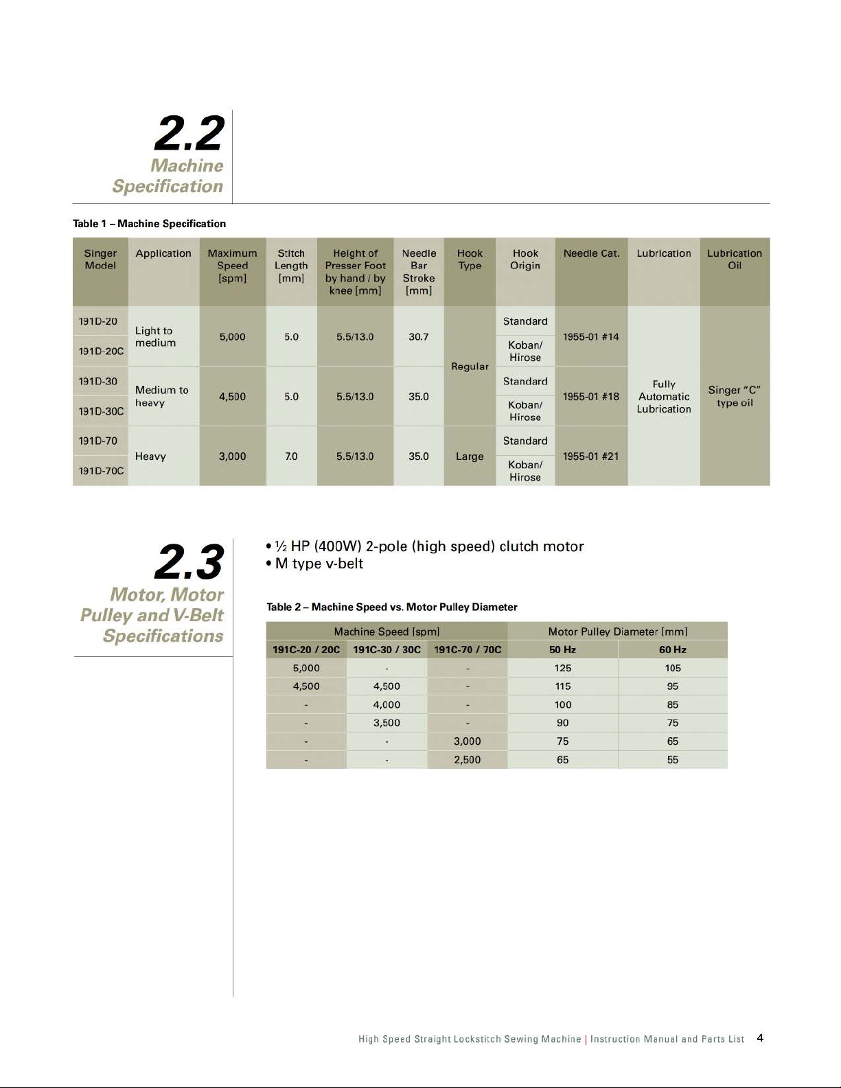
Specification
Tab
le 1 -
Mac
hin
Singe
r Application
Model
1910-
20
light
20C
medium
Medium
heavy
1910-
1910-30
1910-30C
2.2
Machine
e Specification
Maximum
Speed
to
to
[spm)
5,000
4,500
Stitch
Length
[mm)
5.0
5.0
Height
Presser Foot
by
of
hand
/
knee[mm)
by
5.5/13.0 30.7
5.5/13.0 35.0
Needle Hook Hook Needle Cat. Lubrication
Bar
Stroke
[mm]
Type
Regul
ar
Origin
Standard
Koban/
Hirose
Standard
Koban/
Hirose
1955-01
1955-01
#14
#18
Fully
Automatic
Lubrication
Lubrication
Oil
ucw
Singer
type
oil
1910-70
Heavy 3,000
1910-70C
2.3
Motor,
Pulley
and
Specifications
Motor
V-Belt
7.0
•
V2
HP (400W)
• M
type
Table 2 - Machine Speed vs.
19
1C-20
5,000
4,500 4,500
5.5/13.0 35.0 Large
2-po
v-belt
Machine
/20C
Speed [
191C-30
4,000
3,500
/30C
le
Motor
(high
spm)
speed) clutch
Pulley Diameter
191C-70 / 70C
3,000
2,500
Standard
Koban/
Hirose
1955-01
motor
Motor
50Hz
125
115
100
90
75
65
#21
Pulley Diameter
[mm]
60Hz
105
95
85
75
65
55
High
Speed
Straight Lockstitch Sewing Machine ! Instruction Manual
and
Parts List 4
Page 8
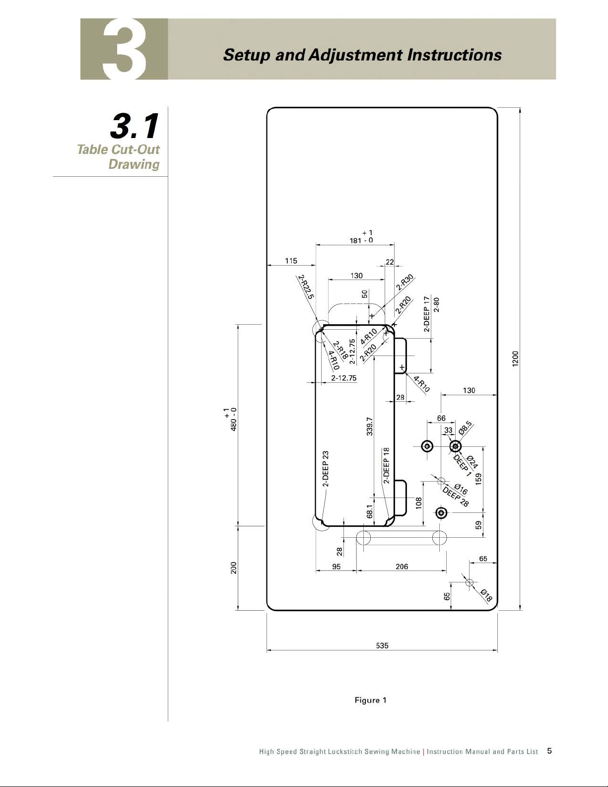
Setup
and
Adjustment Instructions
3.1
Table Cut-Out
Drawing
,---------------------------------~
+ 1
181
- 0
115
-
130
---
0
0
N
~o
+ '
0
~
----
0
0
N
----
.....
ai
""
""
00
N
""
c...
LU
LU
Cl
~
c...
LU
LU
Cl
N
f-
"'
,J
I--"'
00
N
95
'---------------------------~------'
~
I
535
LO
"'
:---
Figure 1
High Speed Straight Lockstitch Sewing
Machine !Instruction
Manual and Parts List 5
Page 9
3.2
Oil
Reservoir
Installation
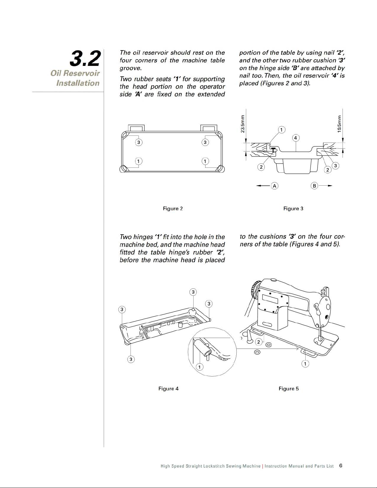
The
oil
reservoir
four
corners
groove.
Two
rubber seats
the head portion on the operator
~~
side
are fixed
should
of
the machine table
'1'
Figure 2 Figure 3
rest on the
for
supporting
on
the extended
of
portion
and the
on the hinge side
nail
placed (Figures 2
the table
other
two
too. Then, the
- ® ®-
by
using
nail
rubber cushion
'8'
are attached
oil
reservoir
and
3).
'4'
'2',
'3'
by
is
Two hinges
machine bed,
fitted the table hinge's
before the machine head is placed
'1'
fit
into the
and
the machine head
Figure 4
hole
in the
rubber
'2',
to the cushions
of
ners
the table (Figures 4
Figure 5
'3'
on
the
four
and
cor-
5).
High Speed Straight Lockstitch Sewing Machine ! Instruction Manual and Parts List 6
Page 10
3.3
Belt Cover
Bobbin Winder
Installation
For safety, the
belt cover should
be installed.
right parts
bobbin winder
should be parallel
belt
machine table.
and
Caution
The
left and
of
the
to the plate
slot
on the
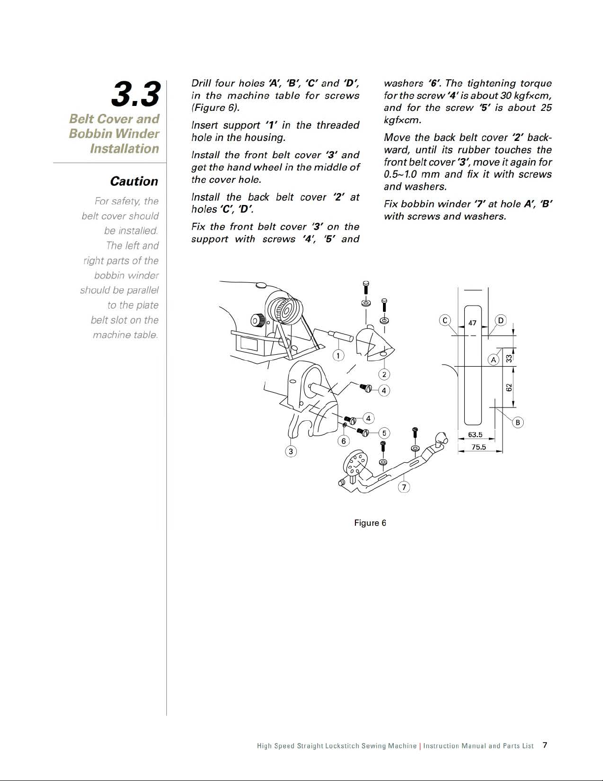
Drill
four
holes J1', '8',
in
the
machine
(Figure
Insert
hole
Install the
get
the
Install the back
holes 'C
Fix the
support
6).
support
in the housing.
front
the
hand
wheel in the
cover
hole.
',
'D'.
front
belt
with
'C'
and
'D:
table
'1' in the threaded
belt
screws '4
cover
belt
cover
for
screws
'3'
middle
cover
'3' on the
',
'5'
'2'
and
of
at
and
washers '6'. The
for
the
and
for
kgfxcm
Move
ward,
front
belt
0.5-1.0
and
washers.
Fix
bobbin
with
screws
screw
the back
until
the
.
cover
mm
'4' is
screw
its
and
winder
and
~
tightening
about
'5' is
belt
cover
rubber
'3',
move
fix
it
'7
'
at
washers.
47
~
torque
30
kgfxcm,
about
touches the
it
again
with
hole A',
'2'
back-
screws
25
for
'8'
Fi
gure
N
CD
1 • 63.5 .1
75
.5
6
High Speed Straight Lockstitch Sewing
Machine !Instruct
ion Manual and Parts List 7
Page 11
3.4
Lubrication
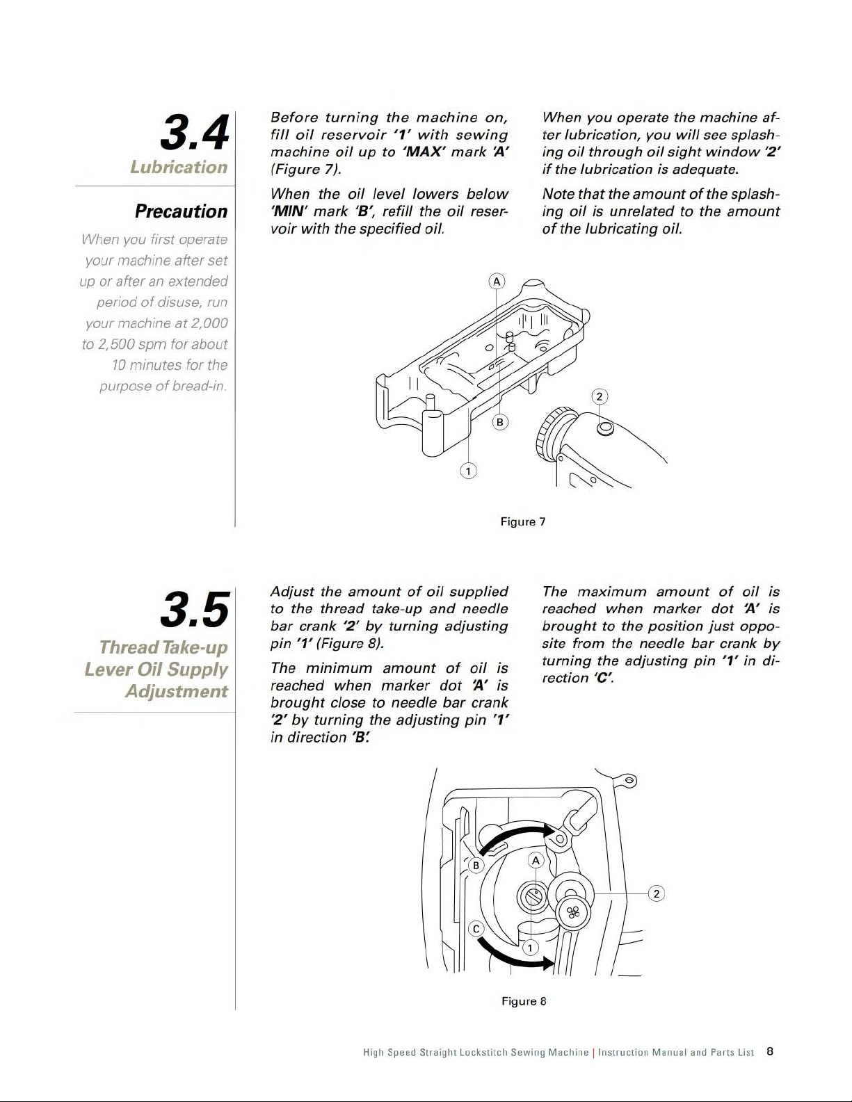
Before
fill
oil
reservoir
machine
(Figure
turning
oil
up
7).
the
machine
'1'
to 'MA
with
X'
on,
sewing
mark
~~
When
ter
ing
if
you
lubrication,
oil
the
lubrication
operate the
through
machine
you
will
see splash-
oil
sight
window
is adequate.
af-
'2'
Precaution
When you first operate
your machine after
up
or
after
an
period
your machine
to
2,
of
disuse,
500 spm for about
10
minutes for the
purpose
of
set
extended
run
at
2,
000
bread-in.
3.5
Thread Take-up
Oil
Lever
Supply
Adjustment
When the
'
MIN' mark '8',
voir
with
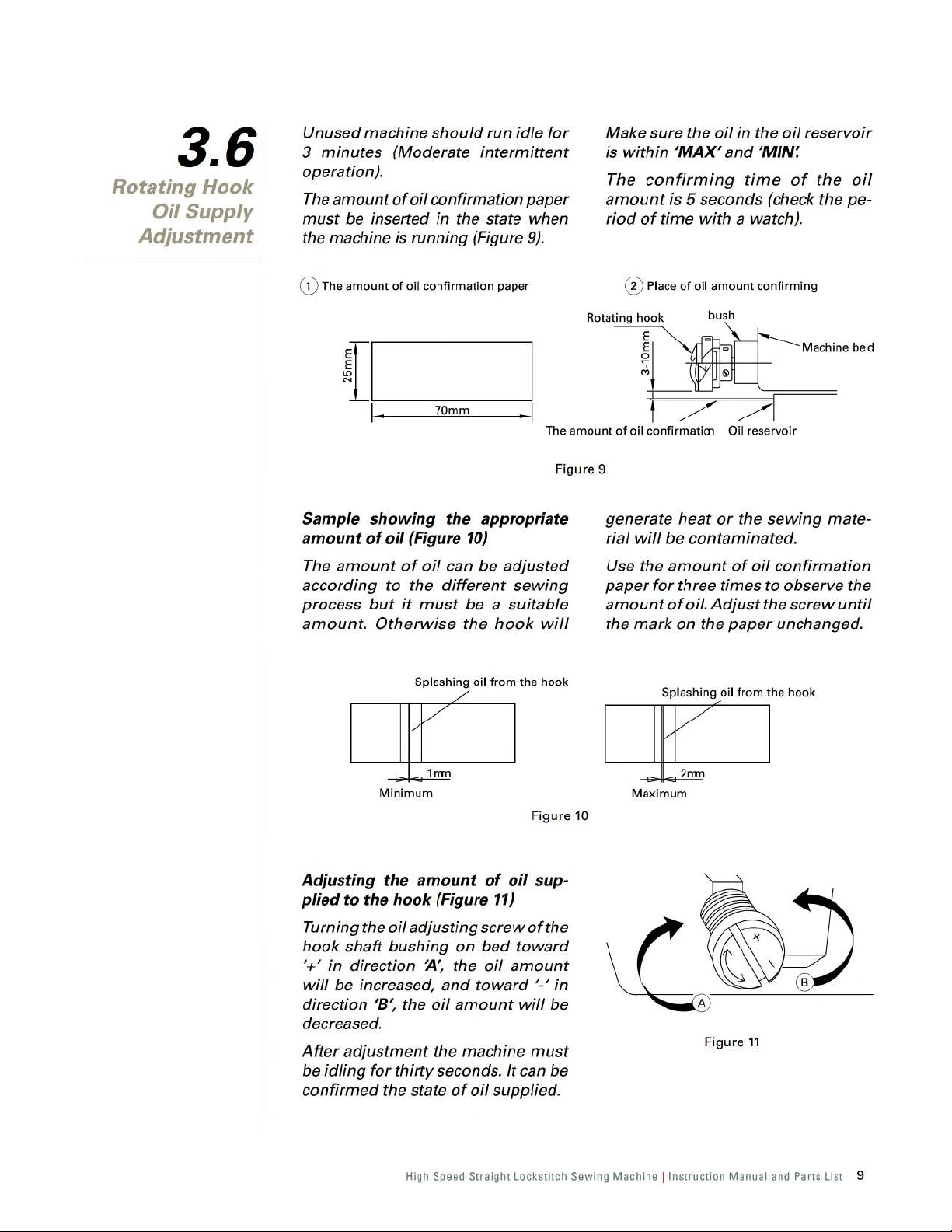
Adjust
to
the
bar
crank
pin
'1' (Figure
The
reached
brought
'2'
by
in
direction
oil
the specified oil.
the
amount
thread
'2'
minimum
when
close to needle
turning
'8:
level
refill
take-up
by
turning
B).
amount
marker
the
adjusting
lowers
the
of
oil
and
dot
below
oil
reser-
supplied
needle
adjusting
of
oil
is
~'
is
bar
crank
pin
'1'
Figure 7
Note
that
ing
oil
is
of
the
lubricating
The
maximum
reached
brought
site
from
turning
rection 'C
the
amount
unrelated
when
to
the
position
the needle
the
adjusting
'.
of
to
oil.
amount
marker
bar
pin
the splash-
the
amount
of
oil
dot
~~
just
oppo-
crank
'1'
in
is
is
by
di-
Figure 8
High Speed Straight Lock
stitch
Sewing Mach ine !
Instruct
ion Manual and Part
s List 8
Page 12
3.6
Rotating Hook
Oil
Supply
Adjustment
Unused machine
3
minutes
operation).
The
amount
must
be inserted in the state when
the machine is running (Figure
G)
The am
ount
~~
!-----_
1 , 70mm , 1
should
(Moderate
of
oil
confirmation paper
of
oil confirmation
intermittent
run idle
paper
for
9).
Make sure the
within
is
The
amount
riod
0 Place
I
amou
nt
The
Fi
gur
of oil confir
e 9
oil
in
the
oil
'MAX'
confirming
is 5 seconds (check the pe-
of
time
of
mat
with
oil
amount
i01
and
'MIN:
time
a watch).
confirm
Oil reser
of
voir
reservoir
the
oil
ing
Machine bed
Sample showing the appropriate
amount
The
according to the
process
amount. Otherwise
Adjusting the
plied to the hook (Figure
Turning the
hook
'+' in direction
will
direction
decreased.
After
be idling
confirmed
of
oil (Figure
amount
shaft bushing on bed
be increased,
adjustment
of
but
it
I
Minimum
oil
adjusting
'8
', the
for
thirty
the state
must
Splashi
//
amount
10)
oil
can be
different
be a suitable
the
ng
oil from
/
1mn
screw
~
:
the
oil
and
toward
oil
amount
the machine
seconds.
of
oil
adjusted
sewing
hook
the
Fi
of
oil sup-
11)
of
toward
amount
'-'
will
must
It
can be
supplied.
will
hook
gure
the
in
be
generate heat
rial
will
Use the
paper
amount
the
mark
Maxim
10
or
the
be contaminated.
amount
for
three
of
on the
um
of
oil
times
oil. Adjust
paper
Fi
gure
11
to observe the
the
sewing
confirmation
unchanged.
mate
screw
until
-
High
Speed
Straight Lockstitch Sewing Machine ! Instruction Manual
and
Parts List 9
Page 13
3.7
Needle
Attachment
Caution
Choose a proper
needle size
according to the
count
of
thread and
the type
The
should be
of
sewing
material used.
power
before attaching
the needle.
supply
cut
off
the
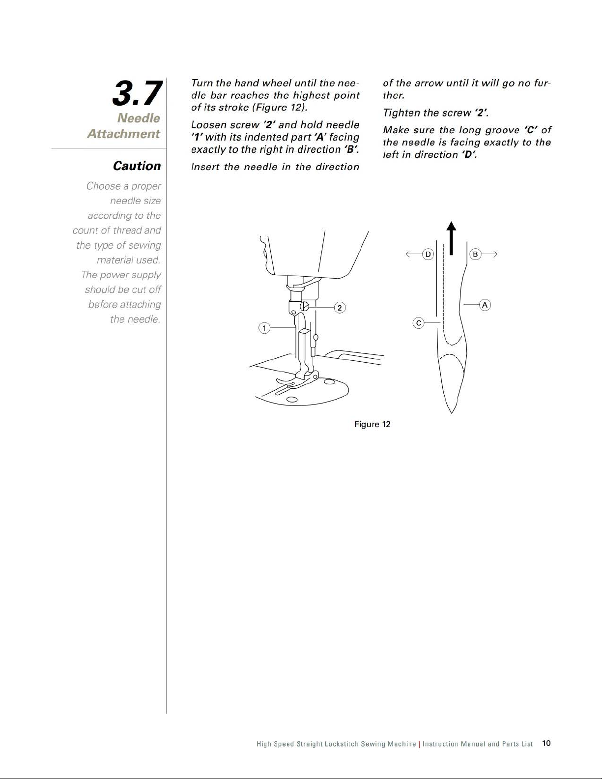
Turn
dle
bar
of
its
stroke
L
oosen
'1'
with
exactly
Insert
hand
reaches
screw
its
indented
to
the
the
needle
wheel
the
(Figure
'2'
and
right
until
the
highest
12).
hold
part
'A'
in
direction '8'.
in
the
direction
nee-
point
needle
facing
of
the
ther
.
Tighten
Make
the
left
sure
needle
in
arrow
direction 'D'.
until
the
screw '2'.
the
is
long
facing
t
it
will
groove
exactly
go
no
'C'
to
fur-
of
the
Fi
gure
12
High Speed
Straight Lock
sti
tch Sewing Machine !
Instruct
ion Manual and Part
s List
10
Page 14
3.8
Bobbin Case
Attachment
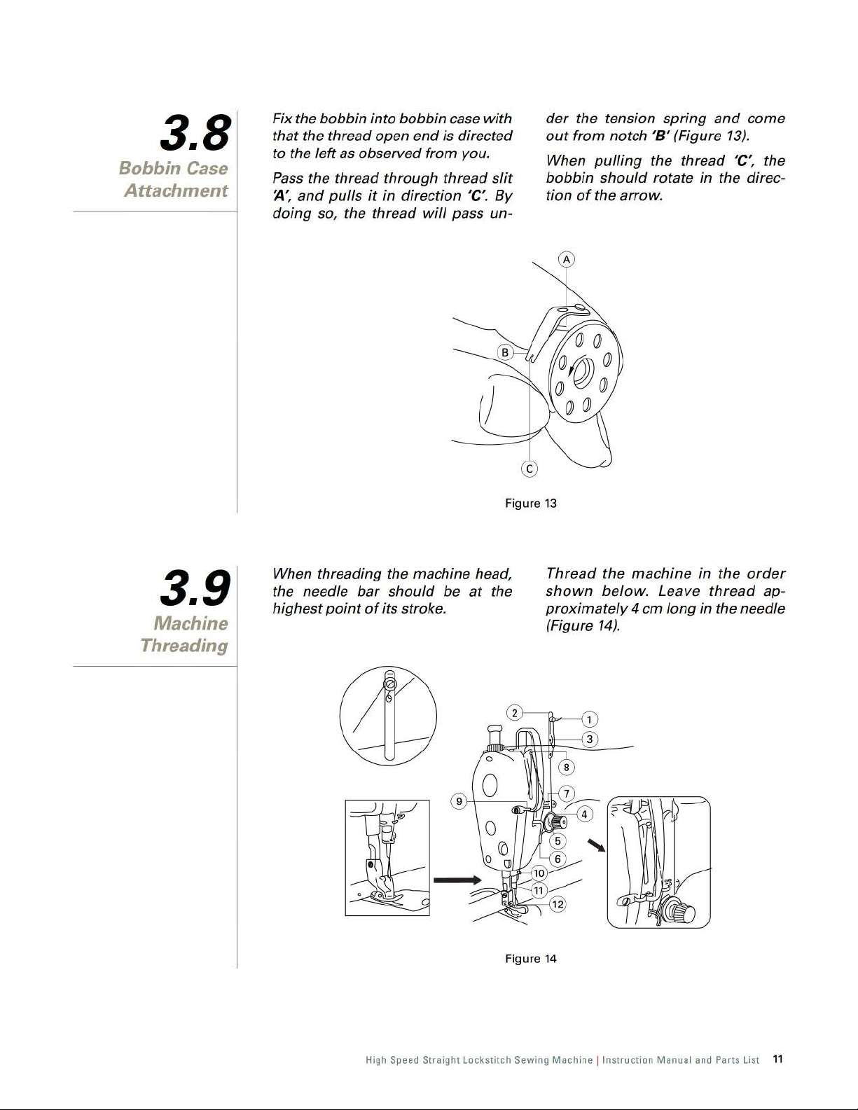
Fix the
that
to the left as observed
Pass the
J4',
doing
bobbin
the thread open
and
pulls
so, the thread
into
thread
it
through
in
bobbin
end
direction 'C'.
case
is directed
from
you.
thread
will
pass un-
with
slit
By
Figure
der
the tension
out
from
When
bobbin
tion
of
13
spring
notch '8 ' (Figure
pulling
should
the
the thread 'C', the
rotate in the direc-
arrow
.
and
13).
come
3.9
Machine
Threading
When threading the machine head,
bar
the needle
highest
point
should
of
its stroke.
be
at
the
Figure
Thread
shown
proximately
(Figure
14
the
below
14).
machine
. Leave
4 em
long
in
the
order
thread ap-
in
the needle
High Speed Straight Lockstitch Sewing Machine ! Instruction Manual and Parts List 11
Page 15

3.10
Stitch Length
Adjustment
Turn
stitch length dial '1' in the direc-
tion
of
the arrow, and align the
sired number to marker
machine arm (Figure
The
indication
meters.
of
dot
15)
.
the dial is in milli-
~,
de-
on
the
Fi
When
you want to decrease the stitch
length, turn stitch length dial
pressing feed reverse lever
of
the arrow.
gure
direction
15
'1' while
'2' in the
3.11
Thread Tension
Adjustment
Adjusting needle thre
(Fi
gur
e 16)
Adjust
using
cording
tions.
Turn the
tion ~
Turn the
(in direction
decrease.
the tension
tension adjusting
to
different
nut
'),
the tension
nut
of
'1' clockwise (in direc-
'1' counterclockwise
'8
'),
the tension
ad
tension
needle thread
nut
'1' ac-
sewing
will
condi-
increase.
will
Adjusting the bobbin thre
sion (Figure 17)
Turn
the
tension
clockwise (in direction 'C'), the
bin
thread
Turn
the
screw
(in direction
tension
will
adjusting
tension
'2'
counterclockwise
'D
'),
the
decrease.
will
bobbin
ad
screw
increase.
thread
ten-
'2'
bob-
Fi
gure
16
High Speed Straight Lockstitch Sewing Machine ! Instruction Manual
Figure 17
and
Parts List
12
Page 16

3.12
Thread
Take-Up Spring
Adjustment
The
adjustment
thread take-up spring (Figure 18)
Loosen setting
Turn the
clockwise (in
stroke
will
of
the thr
be
increased.
Turn the
c
ounter
-clockwise (
the stroke
spring
will
of
the
stroke
screw
thread
'2
tension
direction
ead
take- up
thread
of
tension
the
in
direction
thread
be decreased.
'.
of
post
~
'),
spring
post
'8 '
take-up
the
'3'
the
'3'
),
Loosen setting screw '4'
the tension
Turn the tension
in
direction
(
spring
Tu
rn the tension
ter
clockwise (in
pressure
•
Usually
'1' has been
fore
leaving the factory.
will
, the
post
'3
post
~'),
the pressure
be
increased.
direction
will
be decreased.
thread
properly
'.
'3' clockwise
pos
t '3' coun-
take-
adjusted
and
of
'8'), the
up
spring
turn
the
be-
Adjusting the pressure
take-up spring '1' (Figure 19)
Loosen
out
setting
thread
tensi
Figure
screw
on
of
the thre ad
'2'
and
assembly
18
take
'5'.
• Only wh
or
using
ment
necessary.
en
sewing
special
special clothes
thread
Fi
gure
is readjust-
19
High Speed
Straight
Lockst1tch Sewing
Machine !Instruction
Manual and Parts List
13
Page 17

3.13
Knee Lifter
Adjustment
Height
When
standard
10mm.
You
up
lifter
using
can
to
13
adjusting
height
adjust
mm
Fi
the
knee lifter, the
of
presser
the presser
by
turning
screw
gure
'1'
(Figure 20).
20
foot
is
foot
lift
the knee
When the presser
10
mm,
be
sure
that
of
the needle
position
foot
'3'
(Figure
does
bar
not
21
Fi
gure
foot
'2'
).
the
in
hit
21
lifts
to
over
bottom
the presser
its
end
lowest
3.14
Presser Foot Lifter
Adjustment
Turn the presser
direction
(Figure 22).
The presser
5.5
mm
~~
and
to
lift
foot
stop.
foot
lifter
the presser
will
go
up
'1'
in
foot
about
The presser
original
turned
ure 23).
position
down
foot
in
will
go
back to its
when
direction
the
lifter
'8'
is
(Fig-
Figure 22
High Speed Straight Lockstitch Sewing Machine ! Instruction Manual
Figure 23
and
Parts List
14
Page 18

3.15
Presser Foot
Pressure
Adjustment
Loosen the
presser
wise (in
of
(Figure
Turn the
wise (in
sure
creased.
33-36mm
the
of
spring
direction
presser
24).
regulator
direction
the
nut
'2;
regulator
J1'),
foot
presser
and
'1'
the pressure
will
be increased
'1'
counter
'8'),
the
foot
will
turn
clock-
clock-
be
the
pres-
de-
Tighten
For
general
standard
the
spring
33-36
nut
'2'.
sewing
height
regulator
mm
(5
kg).
'1'
of
the fabrics,
of
the
will
be
presser
around
Figure 24
High Speed Straight Lockstitch Sewing Machine ! Instruction Manual
and
Parts List
15
Page 19

3.16
Feed Timing
Adjustment
Caution
If
the feed
eccentric cam is
moved too
the needle will
be broken.
far,
Loosen screws
eccentric
eccentric
of
the
of
the arrow,
screws
For the
so
that
and
are flush
cam
cam
arrow
'2'
standard
the
the
top
with
or
and
and
top
end
,tf!
I
'2'
and
'1',
move
'1'
in
the
opposite
firmly
'3'
(Figure 25).
adjustment,
surface
top
of
of
needle eyelet
surface
'3'
in
feed
the feed
direction
direction
tighten the
adjust
feed
dog
of
throat
plate
when
below
To
advance the feed
to
prevent
move
direction
To
delay
increase stitch tightness,
feed eccentric
from
the arrow.
the feed
the
throat
uneven
the feed eccentric cam in the
of
the arrow.
the feed
cam
dog
plate.
timing
material
timing
in the
standard
a
dvanc
descends
in
order
feed,
in
order
move
ed
the
direction
to
~~
0(~~
Figure 25
High Speed Straight Lockstitch Sewing Mach ine !
Instruct
ion Man ual
and Parts List
16
Page 20

3.17
Feed Dog Height
Adjustment
Caution
If
the screw
is tightening
too much, the
crank
be worn out.
'1'
'2'
will
When the feed
est
position,
above the
plate
top
'8 ' as the
each machine
dog J4' is
the teeth
surface
below
variety
(Figure 26).
at
should
of
the
height
its
high-
throat
be
for
Loosen
Move
screw
the feed
'2'
of
bar
crank '1
up
make a correct height.
Securely
tighten
See description bel
screw '2'.
ow
or
for
'.
down
height
to
Figure 26
1910-20 I 20C 0.
1910-30 I 30C 0.80 - 0.90
1910-70/70C
70
- 0.80
1.15 - 1.
25mm
mm
mm
High Sp
eed
Straight Lock
stitch
Sewing Mach ine !
Instruct
ion Manual and Parts List
17
Page 21

3.18
Needle to
Rotating
Hook Relation
Adjustment
Precaution
If
the clearance
is too small, the
rotating hook points
will
wear out, and
too big,
When replacing the
should
it
will
cause
the skip stitch
rotating hook,
be
usmg the
origmal one.
it
Adjusting the height
bar
(Figure 27)
Turn
the
handwheel
dle
bar
has been
point
, loosen
The
line
align
with
bar
lower
tighten
~
,
the
bushing
the
setscrew
the
setscrew
on
the
bottom
'3; then
of
the needle
unt
il
at
the
needle
end
of
'1:
the nee-
lowest
'1'.
bar
'2'
needle
securely
Adjusting the position
ing hook
Loosen
screws
til
the
wi
th
lower
After
the
with
make
the
'5' is
two
rotating
and
turn
the
line
'8'
on
needle
the
bottom
bushing '3'.
the
above
rotating
the
center
sure the clearance
needle
end
adjustments
hook
point
of
needle
and the rotat
0.04-0.1 mm.
handwheel un-
of
hook
of
needle
the rotat-
set
bar
align
bar
steps
'5'
aligns
'4',
and
between
ing
hook
-
,
F
igure
27
High Speed Straight Lockstitch Sewi
ng
Machine ! Instruction Manual and Parts List
18
Page 22

3.19
Presser
Bar Height
Adjustment
Loosen
adjust
When the presser
highest, the distance
setscrew
the
height
'1' (Figure 28)
of
the
foot
and
presser
rises to the
between
bar
the
.
throat
5.5
Tighten the
justment.
plate
mm
(Figure 29).
and
the
setscrew
presser
'1'
after
foot
is
ad-
Figure 28
Figure
29
High Speed Straight Lockstitch Sewing Machine ! Instruction Manual
and
Parts List
19
Page 23

3.20
Thread
Up
Adjustment
Take-
Stroke
When
terial,
the
the length
the
When
the
sewing
the
left
(in
thread
sewing
thread
for
thread
guides
direction
of
thread
take-up.
light
guides
heavy
J4')
pulled
weight
'1'
move
weight ma-
'1'
move
to
to
increase
out
by
material,
to
the
right
(in direction '8 ')
of
the length
the
thread
When
guide
the screw that is standard (Figure
marker
'1'
thread
take-up.
line
is aligned with the center
'C'
to
decrease
pulled
on
the
out
thread
by
of
30).
Fi
gur
e 30
High Speed Straight Lockstitch Sewing Machine ! Instruction Manual
and
Parts List
20
Page 24

Maintenance
4.1
Machine Head
Cleaning
4.2
Lubrication
4.3
Safety
Inspection
Clean the machine
a
soft
and
dry
cloth to
of
dust
excess
Do
not
use
ner
to
wipe
If
the
machine
time
, lubricate the machine
ding
to
3.4 to
3.6
Check
vices are
justed
Check
screws
adequately
periodically
.
if
of
on the machine head.
any
kind
the surface.
was
the
instructions
.
properly
all
fixing
the
machine
tighten.
periodically
remove
of
lacquer
idle
for a long
of
if
all
safety de-
installed
and
and ad-
supporting
head
with
the
thin
accor
topics
are
-
-
Check
worn
Check
the electrical
power
ged.
if
the
and
if
there is
cord
v-belt
if
it
motor
and
is
not
has the
no
and
plug
excessively
right
tension.
overheating
check
if
are
not
dama
in
the
-
High Speed Straight Lockstitch Sewing Machine ! Instruction Manual
and
Parts List 21
Page 25

Troubleshooting
Problems
Needle
break
1.
Needle is installed wrong
2. Wrong needle type
3. Needle is bended
4. Wrong relation
5. Needle doesn't
or
presser foot
1.
Low
quality thread
2. Thread
3. Wrong threading
is
Possible Causes
with
center
thicker than needle hole
4. Thread tension is too strong
Thread break
Skip stitches
Loosen stitches
Wrinkled stitches 3. Inadequate pressure
5. Needle is installed wrong
6. Thread stand installed wrong
7.
Thread tension disc, thread guide, needle,
and
needle plate are burred
B.
Wrong relation with rotary
7. Wrong relation
2. Wrong threading 2. Rethread the machine correctly
3. Needle
4. Inadequate thread tension
5. Hook
point
6. Needle is bended
1. Wrong threading
2. Thread is thicker than needle hole
3. Inadequate thread tension
4. Wrong setting
1. Thread tension is too strong 1. Readjust the thread tension
2.
Take-up
4. Inadequate
5. Needle
of
needle
is
installed wrong
is damaged
of
needle
spring is too strong
height
of
is
too thick
Possible Solutio
1. Install needle correctly
or size
2. Use proper needle for fabric
3. Replace needle
rotary hook
the needle hole
of
throat plate
4. Readjust the rotary
5. Readjust the needle plate and presser foot
1. Change the thread
2. Use proper needle
hook
for
fabric and thread
3. Rethreaded the machine correctly
4. Readjust the thread tension
5. Install needle correctly
6. Install thread stand correctly
hook
hook
and
hook
point
point
7.
Grind off. polish
B. Readjust needle
1. Readjust needle
or
replace
and
and
hook
hook
3. Installed needle correctly
4.
Readjust the thread tension
5. Replace
by a new
part
6. Replace needle
1. Rethread the machine correctly
2. Use proper needle for fabric and thread
3. Readjust the thread tension
and
hook
point
of
presser foot 3. Readjust the presser foot pressure
feed dog 4. Readjust the feed
4.
Readjust needle
and
hook
2. Readjust the take-up spring
dog
5. Use proper needle for fabric and thread
ns
and
thread
nut
by a new
point
relation
point
nut
nut
point
nut
parts
High Speed Straight Lockstitch Sewing Machine ! Instruction Manual and Parts List
22
Page 26

Parts List
Page 27

Frame
and
Components
6.1
Cover
Part
No
No
2
3
4
5
.
10101034
10122096
101511010
10112024
10122005
.
Description
Face
plate
Face
plate gasket
Screw SM1/8x44 L=4
Arm
oil
shield assembly
plug 2 2 2 2 2 2
Rubber
High Speed Straight Lockstitch Sewing Machine ! Instruction Manual and Parts List
Oty
.
20
20C
30
30C
70
1 1 1 1 1 1
70C
24
Page 28

Frame
and
Components
6.
Cover
1
No.
10 10122006
11
12 100017
13
14
15
17
18
19
20
21
22 10127002 Tension
23 10112006 Tension disk
24
25
26
27
28 101S15005
29
30 10126002 Tension releasing
31
32
33
34
35
36
37
38 10115002
39 10127009
40
41
42
43
44
45
46
47 11237003
48
49 10112008 Thread
50
51
52 101S30003 Hi
53
54
Part No.
6 10122003
101
S11001
7
8 10112063
10122097
9
10122007
10113003
J900112101S11004
10113004
101S11007
1011301500 Thread
400597
101S16001
10112007 Tension
10127017
10112005
101S30002 Tension
10127001
10103011
101S15006
10115001
10115005
10115014
101S17002
10113005
101
10122003
101
1011500200
101
101S12001
10112002
101S11002
J900191-
R03001
10112062
10112064
101
101
10127004 Tension
J900112-002
J900112-004
001
S11007
S11001
S11019
xxx
1300700 Thread
12009 Tension
Description
Rubber
plug
Screw
SM3/16x28
Side
plate
Side
plate
gasket
Rubber
plug
Rubber
plug
Frame
Two-hole
Singer
Screw
Right
Screw SM1
Thread
Tension
Tension
Thread
Thread
Tension
Screw
Screw
Throat
Throat
Thr
Screw
Left
Screw
Rubber plug
Screw
Slide
Slide
Slide
Screw
Screw
Scale
Screw
Mo
Model
Thread take-up
Thread
Safety
Singer
thread
"S"
cameo
SM3/16
arm
thread
1164
tension
tension
adjusting
disk
stopper
spring
spring
holder
tension
post
take-up
post
socket
SM9/64x40
SM15/64x28 L=7
plate
plate
oat
plate
SM11/64 x
arm
thread
SM11/64x40 L=6
SM3/16x28 L=9 3 3 3 3 3 3
plate
assembly
plate
plate
spring
SM3/32x56 L=1.9 2 2 2 2 2 2
stud
base
plate
SM11/64 x
del
plate
plate
rivet
take-
up
label
guide
rod
guide
rod
disk
spring
nge
screw
logo
resin pl
Oty
.
20 20C 30 30C
1 1
1
L=9 8 8 8 8 8 8
eyelet
guide
x 28 L=6 2 2 2 2 2 2
guide
x 40 L=6
regulator
regulator
disk
spring
guide
lever
lever
assembly
assembly
nut
L=5.5
pin
40
L=8.5 2 2 2 2 2 2
40
L=5 2 2 2 2 2 2
cover
cover
assembly
ate
(front)
1
1 1 1 1 1 1
1 1 1 0 0
0 0 0 0
1 1 0 0 0 0
0 0
1 1 1 1
2 2 2 2 2 2
1 1 0 0 0 0
0 0 0 0
0 0 0 0 1
2 2 2 2 2 2
1 1 1 1
4 4 4
4
1 1 1 1 1
1 1
2 2 2 2 2 2
1 0 0
0 0
1 1 1 1 1
2 2
0 0
2
70
70C
1 1 1
1 1
4
2 2
2
4
High Speed Straight Lockstitch Sewing Machine ! Instruction Manual
and
Parts List
25
Page 29

6.2
Arm
and
Take-Up Lever
Components
Shaft
Thread
High Speed Straight Lockstitch Sewing Machine ! Instruction Manual and Parts List
26
Page 30

6.2
Arm
and
Take-Up Lever
Components
Shaft
Thread
Oty
Part
No
S15001
.
Description
up
crank shaft
Screw
SM15/64 x 28 L=10.5
Screw
Thread take-
Thread take-
Needle
Needle
Screw
Screw
Counter
Screw
Feed
Screw SMI
Arm
Snap
Thrust
Arm
adjusting
Arm
T
hrust
Screw
Arm
Roller
amount
up lever link
up
lever
link
up lever link
bar
crank
bar
crank 0 0 1 1 0 0
bar
crank 0 0 0 0
bar
crank
SM9/64 x 40 L=4.8
SM9/32 x 28 L=16
weight
SM1/4 x40 L=6 2 2 2 2 2 2
ring
drive
eccentric
drive
eccentric
/4
x 40
shaft
bushing
ring
collar
40
shaft
bushing
collar
shaft
bushing
collar
whee
l 1 1 1 1
SM
15/64 x 28 L=15 2 2 2 2 2 2
shaft
felt
adjustin
assembly 0 0 0 0 1 1
rod
cam
cam
L=1
1 2 2 2 2 2 2
(rear)
L=6 2 2 2 2 2 2
(front)
(middle)
pin
20 20C 30 30C
1 1
0 0
1
0 0 0 0
1 1 1 1 1
1 1 1
No
.
10126001 Thread take101
2
3 101S3001
10105001
4
10105006 Thread take1223800300
10124001 Needle bearing 2 2 2 2 2 2
6
1011000100
7
1011000400 Needle
1221000100 Needle
8 10105002
101S15007
9
101S15004
10
10104001
11
12 101S15002
10122010 Rubber
13
14 101S11003 Screw SM9/32 x 28 L=6 1
10110003 Feed
15
400058
16
101S11013
10103001
17
10122008 Oil seal 2 2 2 2 2 2
18
H03002
19
10108001
20
21
101S15007 Screw SM1 /4 x
10103004
22
10112003 Oil
23
10103003
24
25 101S15006 Screw
10112017
26
10135007 Hand
27
101S15008
28
10102001
29
10122012
30
31
101S11005 Oil
.
70
1
1 1 1 1
0 0 0 0
1
0 0 0 0
0 0
1
0 0
1 1 1
1
70C
1
High Speed Straight Lockstitch Sewing Machine ! Instruction Manual
and
Parts List
27
Page 31

6.3
Needle
Upright Shaft
Rotating Hook
Driving Shaft
Components
Bar,
and
Part
No
13009
.
Description
Cap
bar
Needle
Needle
Needle
Needle
Needle
Screw
Slide block 1 1 1 1
Needle
Needle
Needle
Needle
High Speed Straight Lockstitch Sewing Machine ! Instruction Manual
bushing
bar
bar
bar
bar
connection
SM9
/64 x
bar
thread
bar
thread
bar
bushing (lower) 1 1
bar
bushing (lower)
(upper) 1 1 1 1
40
L=6
guide
guide
No.
1
2
3
4
5
6
7
8
10122013
10103009
10102002
10102012
10102021
10138002
101 S11005
10109001
10113001
101
10103010
10103023
Oty.
20
20C
30
1 1
0 0
0 0 0 0
1 1
0 0
0 0
0 0 0 0
1 1
0 0 0 0
1 1 1 1
0 0 0 0
30C
and
70
0 0
Parts List
28
Page 32

6.3
Needle
Upright Shaft
Rotating Hook
Driving Shaft
Components
Bar,
and
Part
No
01
01
01
1800
1
08002
101
1
0000000
5008
02006
5006
S11008
.
No
.
101S11006
9
10
10113002
11 1955-
1955-
195512 10125004
13
101 S15009
14
10125003
15 10125002
16 10125001
17 10102007
18
10118003
10818501
19
10103017
101S15006
20
21
10103016
10103015
22
23
10118504
101
10118505
10118509
11018001
10818001
24
101
101S11012
25
26
10112016 Posi
10112032 Posi
27
101 S1
28
101
29
101S1
10122015 T
30
31
10123002
101
32
12202003
10118501
33
10118517
10818502
34
10123003 Oil
101S30005 Oil seal
35
101S1
36
37
10109002
1
01
38
Description
Screw
SM
1/8 x
44
L=4
.5
Need
le
bar
thread
guide
Needle#
Need
Needle#21
Gear
Screw
Pinion
Gear
Pinion
Upright
Bobbin
Bobbin
Upright
Screw
Upright
Hook
Rotating
Rotating
Rotating
Rotating
Rotating
Rotating
Thrust
Screw
Screw
Hook
Screw
Screw
Hook
Hook
Bobbin
Bobbin
Bobbin
Screw
Needle
Screw
14 1 1
le #18
SMI/4 x 40
(upper)
large
(lower)
shaft
shaft
SM3/16
shaft
shaft
hook
hook
hook
hook
hook
hook
collar
SM 11/
tion
finger
tion
finger
SM11/64 x
shaft
hrust coll
SM 11164
shaft
shaft
case 1 1 1 1
case
case
wick
screw
SM3/16 x 28
bar
SM11/
bushing
x28
bushing
bushing
64x
bushing
ar
slid
block gui
64x40
L=8
(upper)
L=9
(lower)
(rear) 1 1 1 1 1
40
L=4 .8 2 2 2
40
L=9.5
(front)
x40
L=3.5 2 2 2 2 2 2
L=12
de
L=B 2 2 2 2 2 2
Oty
.
20
20C
30
1 1 1 1
0 0 0 0
0 0
0 0 0 0
1 1 1 1 1 1
8 8 8 8 8 8
1 1 1 1
0 0 0 0
1
0
0 0
0 0 0
0 0 0 0
0 0 0 0 0
1 1 1 1 1
1 1
0 0 0 0
1 1 1 1 1 1
1 1 1 1
0 0 0 0
0 0 0 0
0 0 0 0 0
1 1 1 1 1 1
1 1
0 0 0 0 0
1
0 0 0 0
1
0 0 0
70
30C
0 0
1 1
0 0
0 0 0
1
0 0
1
2 2
0 0
1 1
0 0
1
70C
0
1
2
0
Speed Straight Lockstitch Sewing Machine ! Instruction Manual
High
and
Parts List
29
Page 33

6.4
Presser Foot
Components
~
i I
I I
! I
I !
High Speed Straight Lockstitch Sewing Machine ! Instruction Manual and Parts List
30
Page 34

6.4
Presser Foot
Components
Part
No
No
.
10111001
101 S11
2
3
001004
1011000200
4
5
1011201100
6
H05009
101
7
1011600100
8
1011600400
1011600800
H05009
9
10112010
10
11
H05009
101S20004
12
13 101S20003
10
112014
14
15 10126003 Connecting
10
112013
16
H05009
17
10
127008 Tension release
18
19 10127003 Tension release
20 10126003 Tension release
21 10112012 Tension release plate
22 101S20002 Tension release screw stud
101S30004
23
24
101
25 10102003 Presser
10127005 Presser
26
10127018
27 10109003 Presser
10102004
28
10113008
29
30
101S
101S11005
31
10103012
32
101S11009
33
34
10128002 Washer
10122034 Pres
35
.
Description
Hand
lifter
010
S20001 Link screw stud 2 2 2 2 2 2
S16002 Presser
15007 Screw
Screw
SM9/64 x
Rubber ri
Hand
Hand
Snap
Presser
Presser
Presser
Snap
Lifting
Snap
Screw
Screw
Lifting
Lifting
Snap
Presser
Presser
Presser
Presser
Screw
Presser
Screw
ng
lifter
cam
assembly
lifter
link
assembly
ring
foot
assembly 1
foot
assembly 0 0 1 1 0 0
foot
assembly 0 0 0 0 1
ring
lever
ring
lever
link
rod
vertical
lever
connecti
ring
return
pin
supporting
spring
regulator
spring
regulator
guide
bar
spring
spring
bar
guide
bar
bar
thread
SM
1/4 x
40
SM
9/64 x 40 L=8.5 2 2 2 2 2 2
bar
bushing (lower)
SM9
/64 x 40 L=l0.5
ser
bar oil (1rotection bushing
40
L=9.5
on
spring
spring
bracket
guide
L=8 1 1 1 1 1 1
rod
nut
pin
Oty
.
20 20C 30 30C
1
1
1
3 3 3 3 3 3
2 2 2 2 2 2
0 0
1 1 1 1
1
0 0 0 0
1 1 1
0 0 0 0
70 70C
1
High Speed Straight Lockstitch Sewing Machine ! Instruction Manual
and
Parts List 31
Page 35

6.5
Feed Mechanism
Components
N
o.
P
art
2
3
4
5
6
7
8
9
10
11
10105005
12212003
10126016
10101004
10103020
10126014
10127010
10126015
0111052
1
12211001
101511022
10105003
400083
10126006
No.
Descrip
tio
n
Feed
regulator
Feed
regulator
Feed
regulator
regulator
Feed
Feed
regulator
Feed
regulator
Spring
Pin 1 1
dia
Feed
Feed
dia
Screw
Feed rock
Feed rock
Pin
High Speed Straight Lockstitch Sewing
connecting
connecting
pin
bushing
screw
l
l 0 0 0 0
SM3
f16X28 L=18
shaft
crank
shaft
crank connecting
rod
rod
connecting
rod
rod
Machine !Instruction
Oty.
20
20C
30
30C
70
1 1 1 1 0 0
0 0 0 0
1
1 1 1
1 1 1 1 0 0
0 0 0 0
1
1
Manual and Parts List
1
0 0
1
1 1
70C
1
0
32
Page 36

6.5
Feed Mechanism
Components
No.
12
13
14
15
16
17
18
19
20
21
22
23
24
25
26
27
28
29
30
31
32
33
34
35
36
37
38
39
40
41
42
43
44
45
Part No.
101S11005
10105004 Feed
10122016
10127012
12227001
H05009
1010400500
101S17003
H05009
101S11005
1012007
10109005
10109004
1010100200 Feed
10126009 Feed
101S15010
101S11005
10126013 Feed
H03001
10114001 Feed
10114004
10114012
101S11018
1010700100
10112018 Feed
10102008 Feed rock
10126011
101S11005
101S16003
10104002 Feed rock
12204003
101S11016
10104004 Feed l
101S11021
101S20005
10102009
10108003
101S15002
Description
Screw
lifting
Rubber
Spring
Spring
Snap
ring
Feed
reverse
Screw
Snap
ring
Screw
Pin
Link
Link
adjust
adjust
Screw
Screw
bar
Retaining
dog
Feed
dog
Feed
dog
Screw
Feed
bar
spring
Pin
Screw
Nut
SM9132X
Feed rock
Screw
ifting
Screw
Screw
Fe
ed
driving
Thrust
Screw
46 10103018 Feed rock
101S11023
47
101S11025
48
H03001
49
10101003 Feed
50
51
101S11016
10128003
52
10104003
53
101S11020
54
55
10103018 Feed dri
56
10108003
101S15002
57
10122017
58
10102010 Feed
59
10103021 Feed
60
61
10101005 Reverse
62
101S15007
101S15011
63
10112019
64
10127011
65
12227002
101S11025
66
67
10126010
GT0569
68
69
GT0570 Feed
Screw
Screw
Retaining
bar
Screw
Washer
Lifting
Screw
Thrust
Screw
Rubber
reverse
reverse
Screw
Screw
Adjusting
Reverse
Reverse feed
Screw
Screw
Washer
adjusting
SM9/64x
40
rock
shaft
ring
arm
assembly
SM9164x
40
link
assembly
link
shaft
SM15/64x28
SM9/64x40
SM118X44
SM9164x
SM3116 X
SM3116 x
collar
SM1/4 x 40
SM3116 x
SM11/64 x
SM3116 x
fork
SM11/64 x
ving
collar
SM1/4 x 40
ring
feed
SM1/4 x 40
SM1/4 x 40
feed
SMI1/64 X 40
shaft
ring
assembly
hook
shaft
28
shaft
crank
shaft
crank
rock
shaft
shaft
bushing
ring
driving
shaft
shaft
shaft
control
link
spring
spring
spring
shaft
L=6
L=6
plate
40
28
shaft
28
L=6
28
40
crank
28
40
bushing
l=6
l=8
L=10
L=6
crank
L=6
L=7
L=6
L=15.5
crank
L=15.5
l=7
L=7
L=14
L=10.5
bushing
lever
guide
L=5
connecting
(back)
rod
Oty.
20
20C
30
1
1
0 0 0 0
1 1 1 1 1 1
2 2 2 2 2 2
2 2 2 2 2 2
2 2 2 2 2 2
2 2 2 2 2 2
1 1 1 1 1 1
2 2 2 2 2 2
2 2 2 2 2 2
2
1 1
0 0 1 1 0 0
0 0 0 0 1 1
2 2 2 2 2 2
1 1 1 1 0 0
0 0 0 0
1 1 1 1 1 1
2 2 2 2 2 2
1 1 1 1 1 1
2 2 2 2 2 2
1 1 1 0 0
0 0 0 0
2 2 2 2 2 2
0 0 0 0
0 0 0 0
0 0 0 0
1 1 0 0
1
2
2
1 1
1 1 1 1
0 0 0 0
30C
2 2
1
70
1 1
1 1
1 1
70C
2
High Speed Straight Lock
stitch
Sewing Mach ine !
Instruct
ion Manual and Parts List
33
Page 37

6.6
Lubrication
Components
High Speed Straight Lockstitch Sewing Machine ! Instruction Manual and Parts List
34
Page 38

6.6
Lubrication
Components
Oty
P
No.
2
3 10121002
4
5
6
7
8
9
10
11
12
13
14
15 101S30009
16 10120001
17 10112020
18
19
20
21 101S30006 Screw 3 3 3 3 3 3
22
23 10112021 Oil
24
25
26
27
28
29
30
31 10112025 Oil wick set plate assembly
32 10112026 Presser plate
33 101S11033 Screw
art No.
101
11004 Oil si
10122019
101S30008
101
S11026
101
S11004
10127015 Oil felt
1012701500
101
12023 Oil ret
10123001
10121003
10112022
101S1
1026
10127014
00
101 S11
011
10
120001
10111003
10111007
10122018
10127013
10
1S30007
10121001
101 S11011
10
136001 Oil tube
101S11010
Description
Rubber ri
Arm
Oil
pump
Screw
Screw
return
Oil
Oil
wick
Oil
tube
Oil
tube
Screw SM15/64 x 28 L=9
Spring
Oil adjusting
Oil
pump
Oil
pump
Screw x 8 3 3 3 3 3 3
Oil
pump
Oil
pump
Oil
pump
pump
Plun
ger
Pl
unger
Pl
unger
Hook
Screw SM11/64 x
Oil wick set plate screw 2 2 2 2 2 2
20 20C 30 30C
ght
window
ng
shaft
oil
tube
support
SM
15/64 x 28 L=9
SM3/16 x 28 L=6
clip
tube
assembly
urn
tube
holder
holder
(lower)
screw
assembly
installing base 1 1 1 1
impeller
cover
impeller
spring
screw
driving
joint
shaft
cover
oil
40
L=9.5
tube
1 1 1 1 1
.
70 70C
1
1
1
High Speed Straight Lockstitch Sewing Machine ! Instruction Manual
and
Parts List
35
Page 39

6.7
Oil
Reservoir
Components
High Speed Straight Lockstitch Sewing Machine ! Instruction Manual and Parts List
36
Page 40

6.7
Oil
Reservoir
Components
Part
No
100600
S30010
.
Descripti
Knee presser l
Oil
Oil
Gasket
Rubber
Screw
Knee
Spring
Snap
Screw
Nut
Screw SM15/64 x 20 L=30 2 2 2 2 2 2
Screw
Knee
Knee
Knee
Oil
Oil
Nail
on
ift
rod
reservoir assembly
reservoir
cushion
ring
lifter
connecting rod
ring
SM9/32x 20 L=20
SM15/64 x 28 2 2 2 2 2 2
lifter
shaft
lifter
plate assembly
lifter
plate
cover
lifter
plate
rod
lifter
plate
rubber
lifter
plate
lifter
plate
holder
reservoir felt
reservoir
cushion
rubber
cushion
20 20C 30 30C
1
1 1 1 1
4
2 2 2 2 2 2
2 2 2 2 2 2
2 2 2 2 2 2
4 4
No
.
10111005
2
1010
3
10101006
10122020
4
10122031
5
101 S11028
6
10122021 Rubber
7
101112027
8
10127016
9
H05010
10
11
10101008 Bracket
101S12003
12
101S16004
13
101S15012
14
10
1S12002
15
10102011
16
10
11202800 Knee
17
10
122024
18
19 10112028 Knee
20 10122025 Knee
21 10112029 Knee
10
112030
22
23 101S12004 Screw SM15/64 x 28 L=15 1 1 1 1
10
122022
24
10
122023
25
101
26
Oty
4 4
4
.
70 70C
4 4 4
4 4
4
High Speed Straight Lockstitch Sewing Machine ! Instruction Manual
and
Parts List
37
Page 41

6.8
Belt Cover,
Bobbin Winder
and
Thread
Components
~
-
~
------------------------1
I I
I I
I I
I
I
I
I
I
:i
MD
I
®~
Stand
---------..1
_______________________
J
High Speed Straight Lockstitch Sewing Machine ! Instruction Manual and Parts List
38
Page 42

6.8
Belt Cover,
Bobbin Winder
and
Thread
Components
Stand
Part
No
No
.
1011100600 Belt
10111006
2
4 1011100900 Belt
10111009
5
6
1011101000
101
7
101
8
101S11030
9
10
10128007 Washer 1 1
101
11
10128006 Washer 2 2 2 2 2 2
12
1011203200
13
14 10112037 Thread
S04006
15
16
10112038 Tension disk 2 2 2 2 2 2
10127018 Tension
17
18 101S16005 Tension
19 S04006 Screw SMI
20 10112035 Rubber brake bracket
21
10122027 Rubber brake
10112036
22
23 10120006
S04017 Screw
24
S04006 Screw
25
10128001 Washer
26
10112032
27
10101010
28
10102012
29
101S30014
30
10128008
31
1013100900 Thread stand assembly
32
10122028
33
10131008
34
35 10131009 Spool
10112039 Spool
36
37 10112040 Spool
10112041
38
S04013 Screw 2 2 2 2 2 2
39
40
10113010
10131010
41
10128009
42
43
10128002 Washer 2 2 2 2 2 2
101S16006
44
10111013
45
10111014
46
10128010 Washer 2 2 2 2 2 2
47
10128006
48
49 N02003
10104003
50
51
101
10102009
52
.
Description
Belt
Belt
Belt
S30012
S11029 Belt
S30011
S11020
Belt
Screw
Screw
Bobbin
Screw
Bobbin
Hinge
Bobbin
Bobbin
Bobbin
Screw 2 2 2 2 2 2
Washer 2 2 2 2 2 2
Rubber cap
Spool
Spool
Thread guide 2 2 2 2 2 2
Spool
Spring
Nut
Spool rest 2 2 2 2 2 2
Spool retainer 2 2 2 2 2 2
Spring
Nut
Screw
Nut
Spool
cover
assembly
cover
cover
back assembly
cover
back
cover
back latch
cover
support
cover
screw
winder
assembly
tension
bracket
SMI1164 x 40 L=7
spring
nut
1164
' x 40 L=5
winder
spring
screw SMI/Sx44 L=12.5
winder
base
winder
pulley
winder
post
post
(lower)
post
(upper)
post
joint
arm
(upper)
arm
(lower)
pin
washer
washer
rest
cushion
20 20C 30 30C
1
2 2 2 2 2 2
2 2 2 2 2 2
1
1 1 1 1 1 1
2 2 2 2 2 2
2 2 2 2 2 2
2 2 2 2 2 2
1 1 1 1 1 1
2
2 2 2 2 2 2
2 2 2 2 2 2
Oty
1 1
1 1
1
2 2 2 2
2
.
70
70C
1 1 1
1 1 1
1
High Speed Straight Lockstitch Sewing Machine ! Instruction Manual
and
Parts List
39
Page 43

6.9
Machine
Accessories
/
"-,
"
//
-----®
High Speed Straight Lockstitch Sewing Machine ! Instruction Manual and Parts List
40
Page 44

6.9
Machine
Accessories
Part
No
No
.
1011203100 Machine
10122026 Machine
2
3 101S30010 Nail Set 4
1955-
4
19551955-
5 10131002
10131003
6
7
10131004
10118003
8
10818501
IP07042-
9
10
101110
1011105500
11
12 101
.
Description
01
01
01
001
11 Machine rest
31001
Needle #14 3 3 0 0 0 0
Needle #18 0 0 3 3 0 0
Needle
Screw
Screw
Screw
Bobbin 3 3 3 3 0 0
Bobbin 0 0 0 0 3 3
Dust
cover
Oil
container
Oil
reservoir
hinge
hinge
#21
driver
driver
driver
plate 2 2 2 2 2 2
rubber
cushion
(large)
(medium)
(small)
pin
magnet
Oty
.
20 20C 30 30C
2 2 2 2 2 2
4
4 4 4 4
0 0 0 0 3 3
1 1 1
1 1 1 1 1
70
70C
1
High Speed Straight Lockstitch Sewing Machine ! Instruction Manual
and
Parts List 41
Page 45

0
....
0
N
c
ro
....,
0
>
Q)
a:
 Loading...