

Page 1

F*rM 2#31S
Rmr, (157)
SEWING MACHINES
INSTRUCTIONS
FOR USING
SINGER*
REVERSIBLE FEED
LOCK STITCH, FOR FAMILY USE
WEtUitiNG
Oil,
Farts, »n
F il AIRS f #R
Y#ui* MACHiNi
^SINGER '
THE SINGER MANÜFACTORING GO.
Lo*K F#ii iHK
; Ftr *5’'
' I'tiRRK A!*f-r '
ERY.' '
;n u. 3. A
Page 2

THE IMPORTANCE OF USING
SINGER*
LUBRICANTS FOR
YOUR ELECTRIC SEWING MACHINE
it
The Best is the Cheapest”
Use SINGER Sewing Machine
Oil on Machine
Knowing from many years* experience
the great importance of using good oil,
SINGER sells an extra quality sewing
machine oil, in cans, especially prepared
for sewing machines.
TO ALL WHOM IT MAY CONCERN:
The improper placing or renewal
of the Trade Mark SINGER’ ’ or any
other of the Trade Marks of The Singer
Manufacturing Company (all of which are
duly Registered Trade Marks) on any
machine that has been repaired» rebuilt,
reconditioned, or altered in any way
whatsoever outside of a SINGER factory or
an authorized SINGER agency is forbidden.
Page 3
20316
INSTRUCTIONS FOR USING
SINGER
15*
SEWING MACHINES
(WITH ATTACHMENTS)
REVERSIBLE FEED
OSCILLATING SHUTTLE
FOR FAMILY USE
THE SINGER MANUFACTURING COMPANY
*A Trade Mark of THE SINGER MANUFACTURING COMPANY
Copyright (c) 1951 by The Singer Manufacturing Company
Page 4
to
Page 5

8
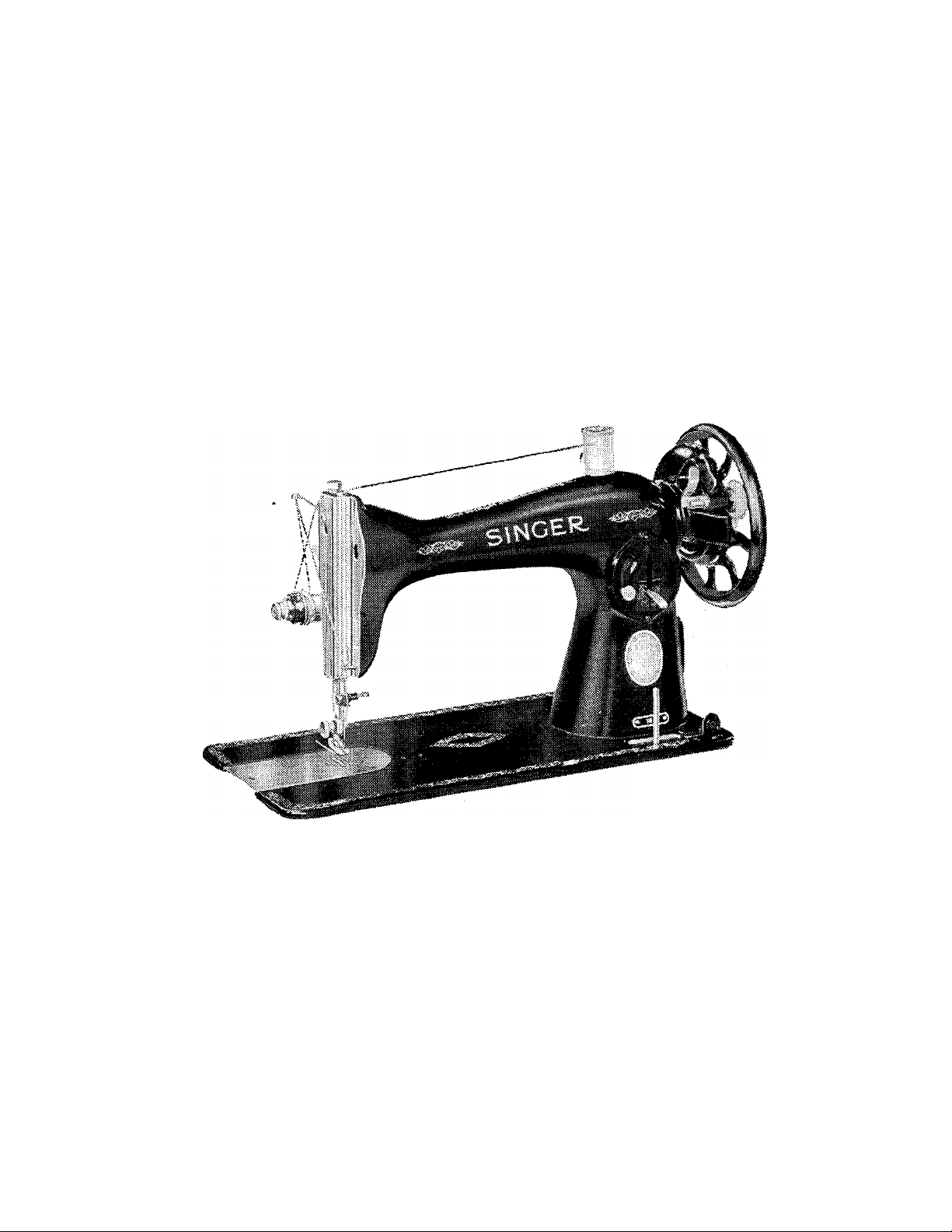
DESCRIPTION
These SINGER family sewing machines will give
you practically life-time service.
Machine 15-88 is intended for operation by foot
power and is regularly equipped with a treadle stand.
Machine 15-89 has a hand driving attachment
and is provided with a wooden base and cover. This
portable outfit can be conveniently carried from
place to place as desired.
Each machine has an oscillating shuttle on a hori
zontal axis and makes the lock stitch. Both machines
have reverse feeding mechanism which enables you
to sew either in a forward or backward direction,
making it easy to back tack and to fasten the ends
of seams.
In addition to plain sewing, a great variety of
pleasing effects such as hemming, binding, edge
stitching, shirring, ruffling, etc., can be produced
with the aid of the attachments furnished with each
machine. These attachments and other popular
SINGER Fashion Aids will enable you to obtain the
much desired tailored appearance of professionally-
made garments and to add new fashion touches or
finishes demanded by swiftly changing styles at a
fraction of the cost of ready-made garments.
READ THIS BOOK CAREFULLY TO GET
THE UTMOST SERVICE
FROM YOUR SEWING MACHINE
Page 6

SINGER SERVICE
Now that you have purchased your new SINGER,
we do not want you to feel that your relations
with us have come to an end. You are cordially
invited to visit your SINGER Shop at any time for
assistance in your sewing problems. You will be
most welcome.
We hope, too, that you will make the SINGER
Shop your headquarters for sewing supplies and
service. Only there or through authorized bonded
SINGER representatives can you secure warranted
SINGER Sewing Machine Oil, needles, belts, parts,
etc., so important in getting the best results from
your machine. And remember, only an authorized
SINGER representative should be allowed to touch
your machine when repairs or adjustments are required.
World-wide SINGER Service has no equal.
Use it!
Page 7
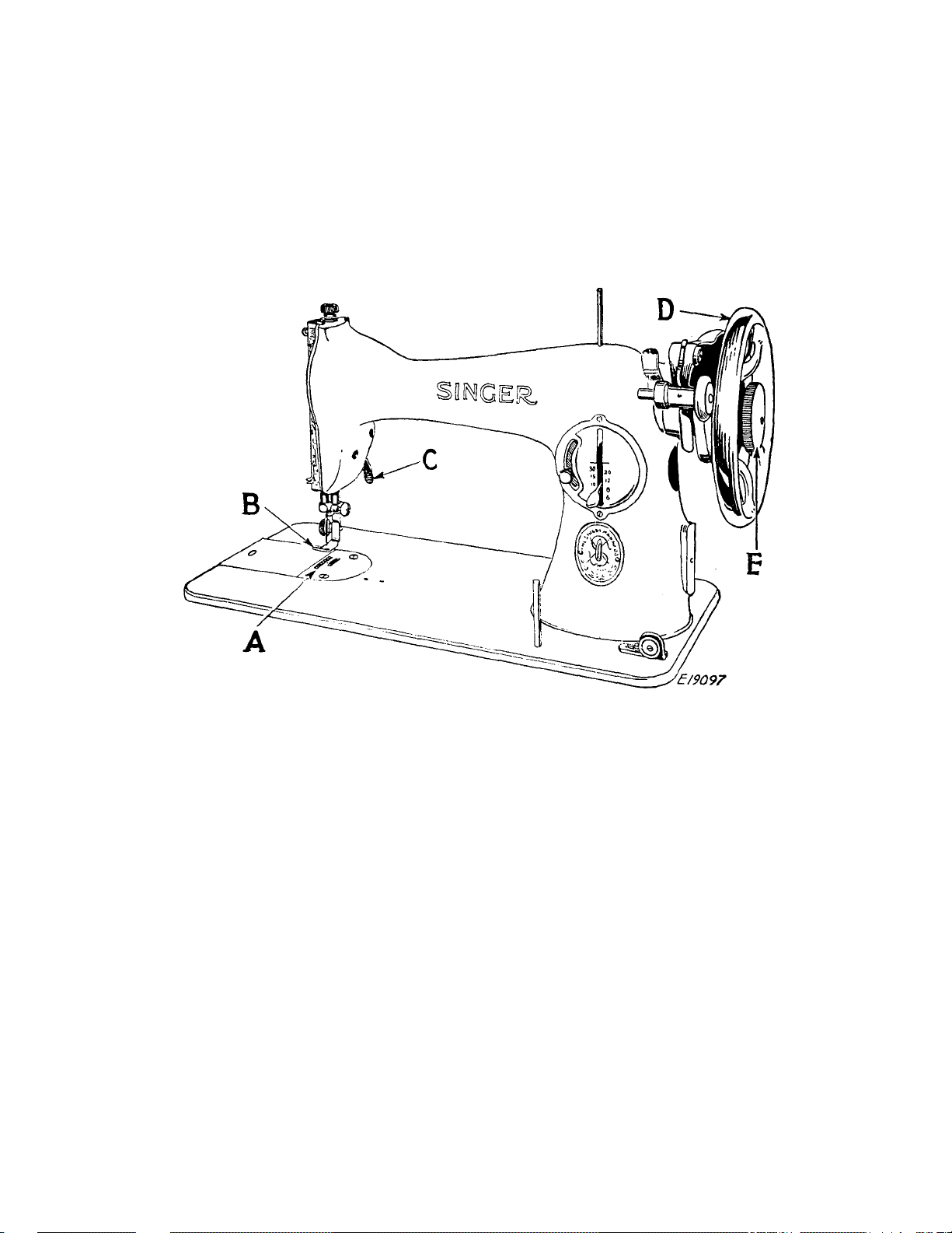
TO OPERATE THE TREADLE MACHINE
(See Fig. 3)
Raise the presser foot B by means of the presser
bar lifter C to prevent injury to the foot B and feed A.
Fig. 3. Front View of the Machine
Hold the balance wheel D with the left hand and,
with the right hand, loosen the stop motion screw E
to release the balance wheel from the stitching
mechanism.
Place your feet upon the treadle and, with the
right hand, turn the balance wheel over toward you.
Continue the balance wheel in motion by an alter
nate pressure of heel and toe on the treadle, until a
regular and easy movement is acquired. Then tighten
the stop motion screw E to connect the balance wheel
with the stitching mechanism.
Place a piece of cloth under the presser foot B and
lower the foot by means of the presser bar lifter C
and operate the machine, without thread, until you
have become accustomed to guiding the material.
Page 8
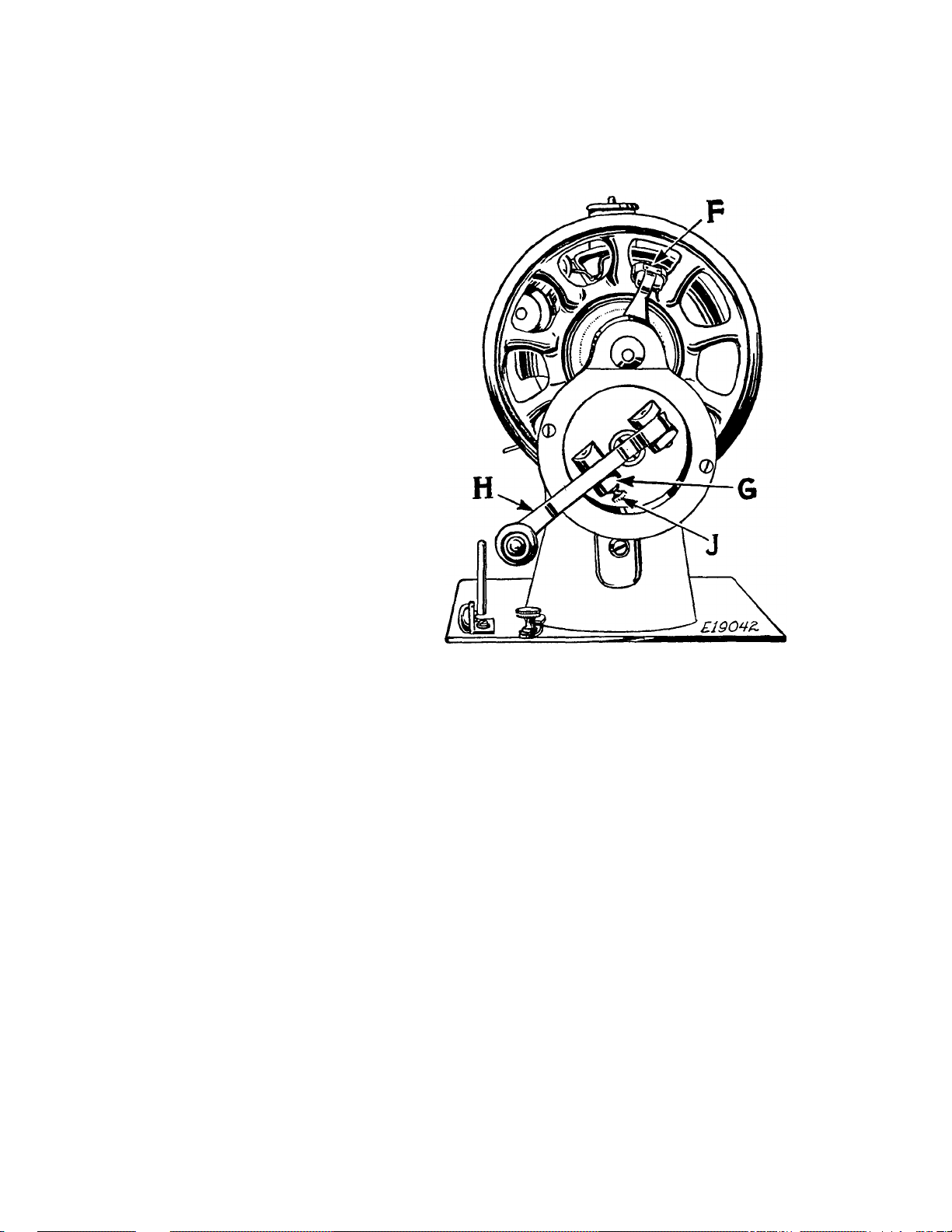
TO OPERATE THE HAND MACHINE
Place the lever H
of the hand driving
attachment in the
socket G and turn
the hinged finger F
back between the
spokes of the balance
wheel, as shown.
6
(See Fig. 4)
Fig. 4. End View of Machine 15-89
Showing Hand Driving Attachment
Raise the presser foot B, Fig. 3 by means of the
presser bar lifter C, Fig. 3 to prevent injury to the
foot B and feed A, Fig. 3.
Turn the lever H of the hand driving attachment
over from you, continuing the motion thus begun
until a regular and easy movement is acquired. Then
tighten the stop motion screw E, Fig. 3 to connect
the balance wheel with the stitching mechanism.
Place a piece of cloth under the presser foot
B, Fig. 3, lower the foot by means of the presser bar
lifter C, Fig. 3 and operate the machine, without
thread, until you have become accustomed to guid
ing the material with the left hand.
NOTE: To release the lever H from the socket G,
withdraw the plunger J and pull out the lever.
Page 9

CHART SHOWING THE RELATIONSHIP OF
TYPES OF FABRICS,
THREAD AND NEEDLE SIZES AND
MACHINE STITCH SETTINGS
MACHINE
TYPES OF
FAB BIGS
THREAD
SIZES
NEEDLE
SIZES
STITCH
SETTINGS
Filmy materials comparable
to Net, Marquisette,
Chiffion, Silk, Organdie,
Ninon, Silk Velvet, Nylon
Sheers.
Sheer materials comparable
to Lawn, Dimity, Voile,
Batiste, Rayon Sheer,
Rayon Crepe, Silk Crepe.
Lightweight materials com
parable to Gingham, Chambray. Sheer Wool Crepe,
Taffeta.
Medium lightweight mater
ials comparable to Poplin,
Pique, Percale, Chintz.
Faille, Bengaline, Wool
Flannel, Wool Crepe, W'ool
Jersey.
Medium heavy materials
comparable to Crash, Gab
ardine, Rep, Corduroy,
Velveteen, Coatings, Suit
ings.
Heavy materials compar
able to Sailcloth, Sturdy
Denim, Ticking, Drill
Cloth, Heavy Coating.
100 Cotton
00 and 000
Silk
80 to 100
Cotton
0 Silk
50 Mercerized
60 to 80
Cotton
A Silk
50 Mercerized
50 to 70
Cotton
A or В Silk
50 Mercerized
40 to 50
Cotton
C Silk
Heavy Duty
Mercerized
30 to 40 Cotton
20to24 Cotton
D Silk
9
11 12-15
14
14
16
18
19
18 or 19
INSIDE
SEAMS
15-20
12
12
10
8
TOP
STITCHING
20-30
15-20
15-18
15-16
12
10
40 to 60 Linen
Very heavy materials com
parable to overcoating.
20 to 24 Cotton
E Silk
21
6
8
Mercerized
Plastic materials.
Cotton
11
10 12
When ordering needles, always specify “Class and
Variety 15x1 ’ ’and state the size and quan ti ty required.
Page 10
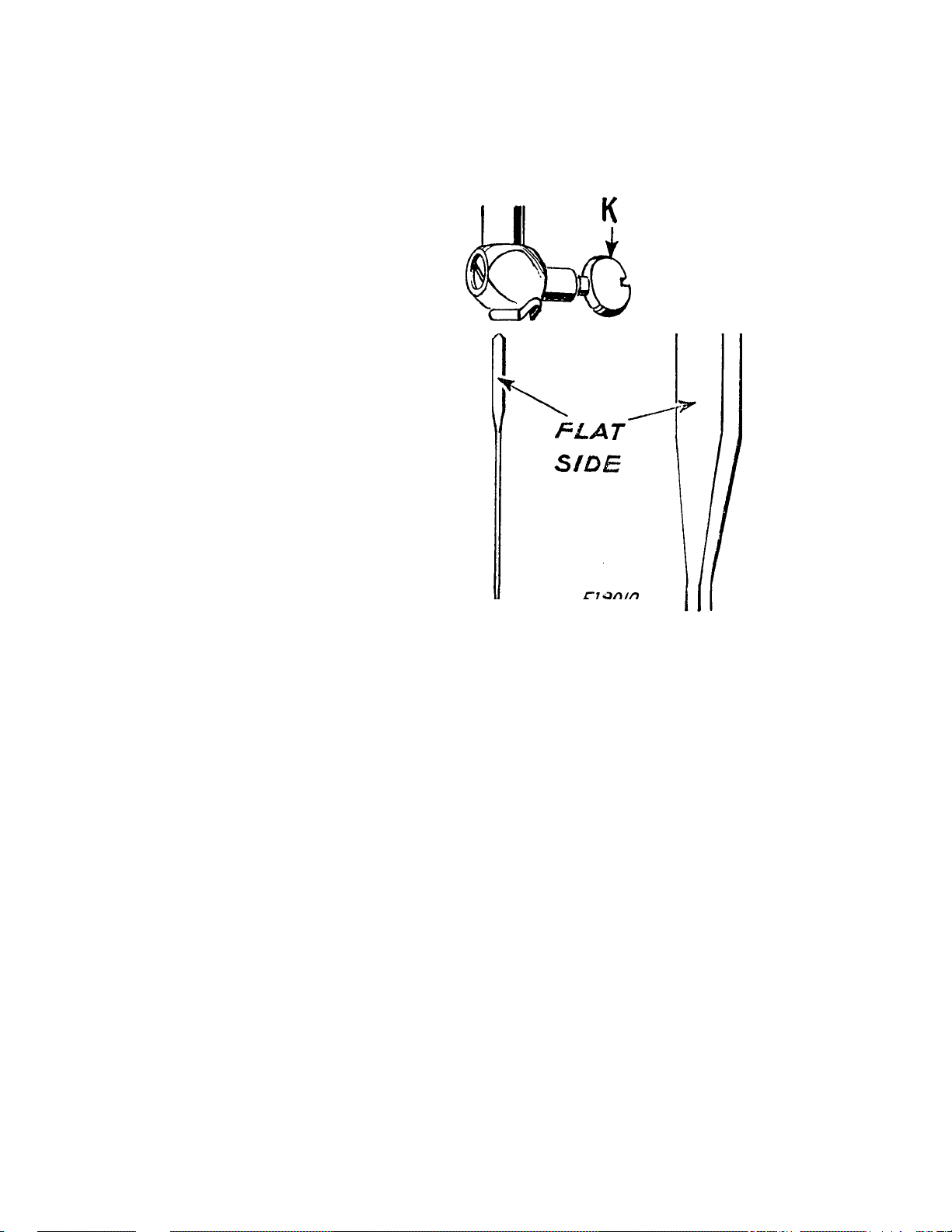
TO SET THE NEEDLE
Select the cor
rect needle ac
cording to the
table on page 7.
Be sure that the
needle is not
blunt or bent.
Raise the needle
bar to its highest
position and
loosen the thumb
screw K in the
needle clamp.
Push the needle
with its flat side
to the left up
into the needle
clamp as far as
it will go, then
tighten the
thumb screw.
8
Eieoio
Fig. 5. Setting the Needle
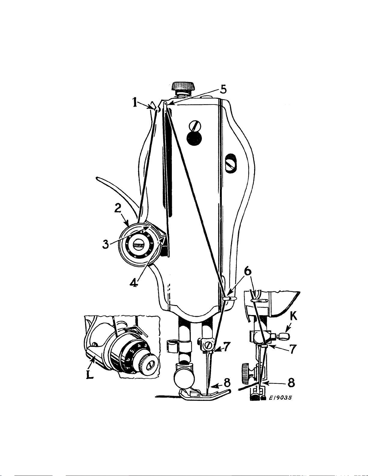
UPPER THREADING
(See Fig. 6 on the Following Page)
Raise the take-up lever 5 to its highest point.
Place the spool of thread on spool pin at top of
machine
Pass the thread through the thread guide 1
Down, under and from back to front between the
tension discs 2 (the thread guard L guiding the
thread between the discs)
Hold the spool tightly and pull the thread against
the take-up spring 4 until it enters the retain
ing fork 3
Pass the thread from back to front through the
hole 5 in the take-up lever
Down through the guide 6 on the face plate
Into the guide 7 on the needle clamp
From right to left through the eye 8 of the needle.
Draw about two inches of thread through the eye
of the needle with which to commence sewing.
Page 11
9
Fig. 6. Upper Threading
Page 12
10
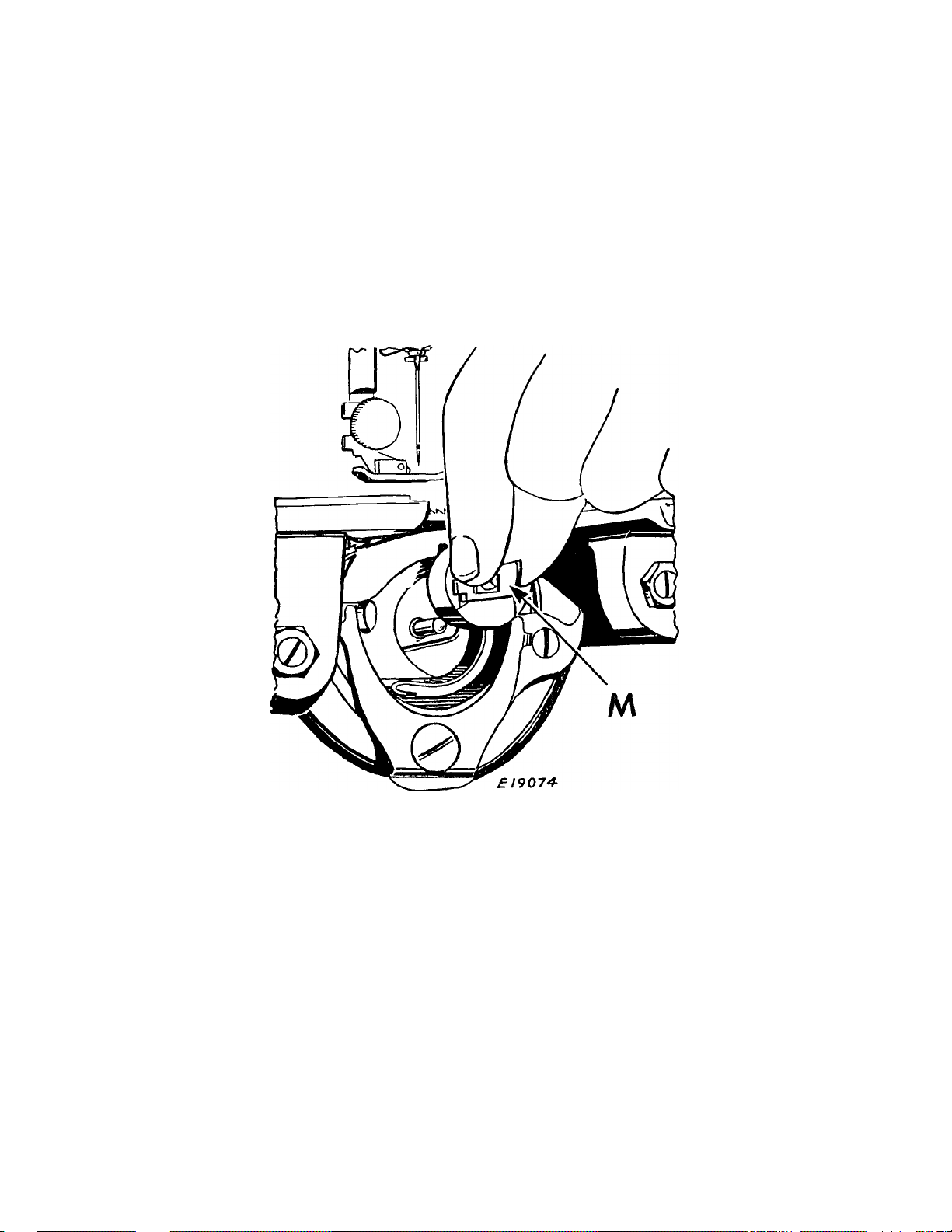
TO REMOVE THE BOBBIN
Raise the take-up lever 5, Fig. 6 to its highest point.
Withdraw the bed slide plate. Reach down with
the left hand and open the bobbin case latch M and
lift out the bobbin case. Release the latch and re
move the bobbin from the bobbin case.
Fig. 7. Removing the Bobbin Case
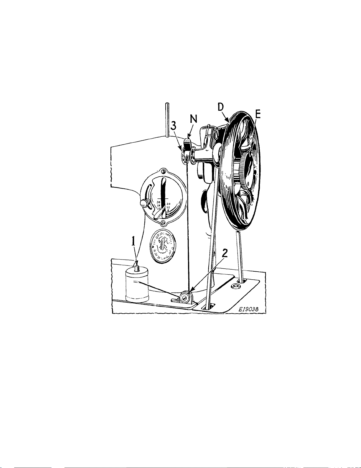
TO WIND THE BOBBIN
(See Fig. 8 on the Following Page)
Hold the balance wheel D with the left hand and,
with the right hand, loosen the stop motion screw E
to release the balance wheel from the stitching
mechanism.
Place the bobbin on the bobbin winder spindle as
far as it will go, having the small pin enter the
hole in the side of the bobbin.
Page 13
11
Place the spool of thread on the spool pin 1
Pass the thread to the right between the tension
discs 2
Up and to the left through one of the holes in the
left side of the bobbin 3, from the inside.
Fig. 8. Winding the Bobbin
The end of the thread must be held by the hand
until a few coils are wound and then should be
broken off.
Press down on the bobbin and the bobbin winder
latch will drop down and hold the bobbin winder
pulley against the hub of the balance wheel.
Then operate the machine the same as for sewing.
When sufficient thread has been wound upon the
bobbin, the bobbin winder is automatically released
from the balance wheel.
Then tighten the stop motion screw E.
Page 14
12
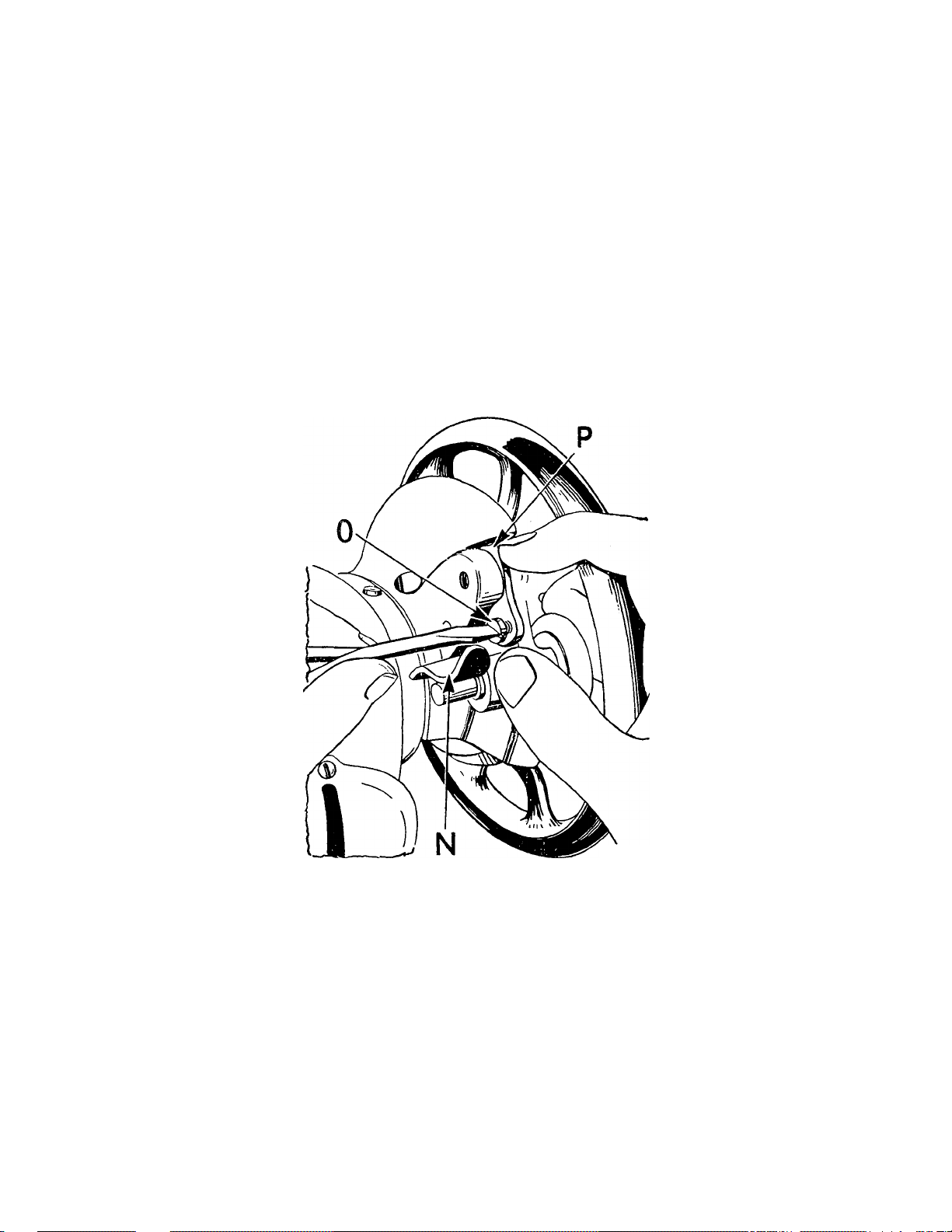
If the pressure of the bobbin winder pulley against
the hub of the balance wheel is insufficient for wind
ing the bobbin, press down the bobbin winder until
the latch N, Fig. 9 drops down and holds it, then
loosen the adjusting screw O, Fig. 9. With the fore
finger, push back the upper end of the slotted plate
P as far as it will go, as shown in Fig. 9, and at the
same time press the bobbin winder pulley against
the hub of the balance wheel, then tighten the
adjusting screw O.
£19072
Fig. 9. Adjustment of Bobbin Windek
If the thread does not wind evenly on the bobbin,
loosen the screw which holds the tension bracket
2, Fig. 8 in position on the bed of the machine and
slide the tension bracket to the right or left, as may
be required, then tighten the screw.
Bobbins can also be wound while the machine
is sewing.
Page 15
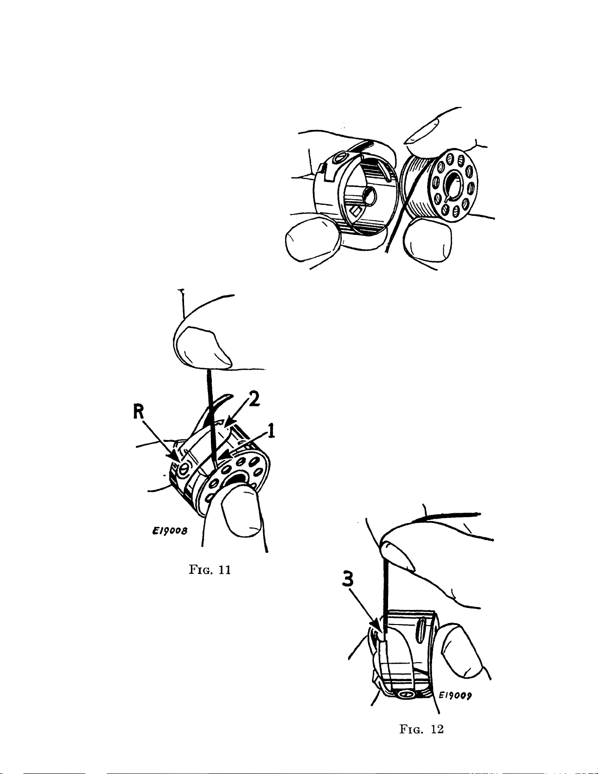
TO THREAD THE BOBBIN CASE
Hold the
bobbin so that
the thread will
unwind in the
direction
shown in
13
Fig. 10.
EI9007
Fig. 10
Hold the bobbin
case as shown in
Fig. 10, and place
the bobbin into it.
Pull the thread into
the slot 1, under the
tension spring 2 and
into the slot 3 at the
end of the spring.
Page 16

14
TO REPLACE THE BOBBIN CASE
Hold the bobbin case by the latch and place it
on the stud T of the shuttle body with the position
finger S opposite the notch at the top of the shuttle
race.
£19096
Fig. 13. Bobbin Case Threaded and Replaced
Release the latch and press the bobbin case back
until the latch enters the groove in the stud. Allow
about three inches of thread to hang free from the
bobbin case and close the bed slide plate.
Page 17
TO PREPARE FOR SEWING
Hold the end of the
needle thread with the
left hand and turn
the balance wheel
over toward you
until the needle goes
down and up again and
the thread take-up
lever 5, Fig. 16 is at its
highest point. Pull up
the needle thread and
15
bobbin thread will come
with it, as shown in
Fig. 14.
Fig. 15
Threads in Position to
Commence Sewing
Fig. 14
Drawing Up the Bobbin Threat
Lay both threads back
under the presser foot diag
onally across the feed, as
shown in Fig. 15, to the right
or left, depending upon
which side of the needle the
material is to be located, so
that when the presser foot
is lowered, the threads will
be firmly held between the
feed and the presser foot.
Page 18
TO COMMENCE SEWING
Be sure to have the
thread take-up lever
5 at its highest point.
Place the material
beneath the presser
foot B, lower the foot
by means of the presser
bar lifter C and com
mence to sew, turning
16
the balance wheel over
toward you.
Never pull the ma
terial along when
stitching. This is liable
to bend the needle.
Guide the material only.
Never operate the
machine without cloth
under presser foot.
Fig, 16
The slide over the bobbin case should be kept
closed when the machine is in operation.
The balance wheel must always turn over toward
the operator.
Page 19

17
TO TURN A CORNER
Stop the machine when the needle is commencing
its upward stroke. Raise the presser foot and turn
the work as desired, using the needle as a pivot,
then lower the presser foot.
BASTING
The longest stitch, No. 6 on the stitch indicator,
adjusted by lever X, Fig. 17, is satisfactory
for basting. These basting stitches can be easily
removed by clipping every sixth stitch and with
drawing the long continuous thread.
Machine basting is firmer, more even and much
quicker than hand basting.
TO SEW BIAS SEAMS
Use a shorter stitch when sewing bias or curved
seams to increase the elasticity of the seam and
to prevent seam failure under strain.
No change in tensions is required.
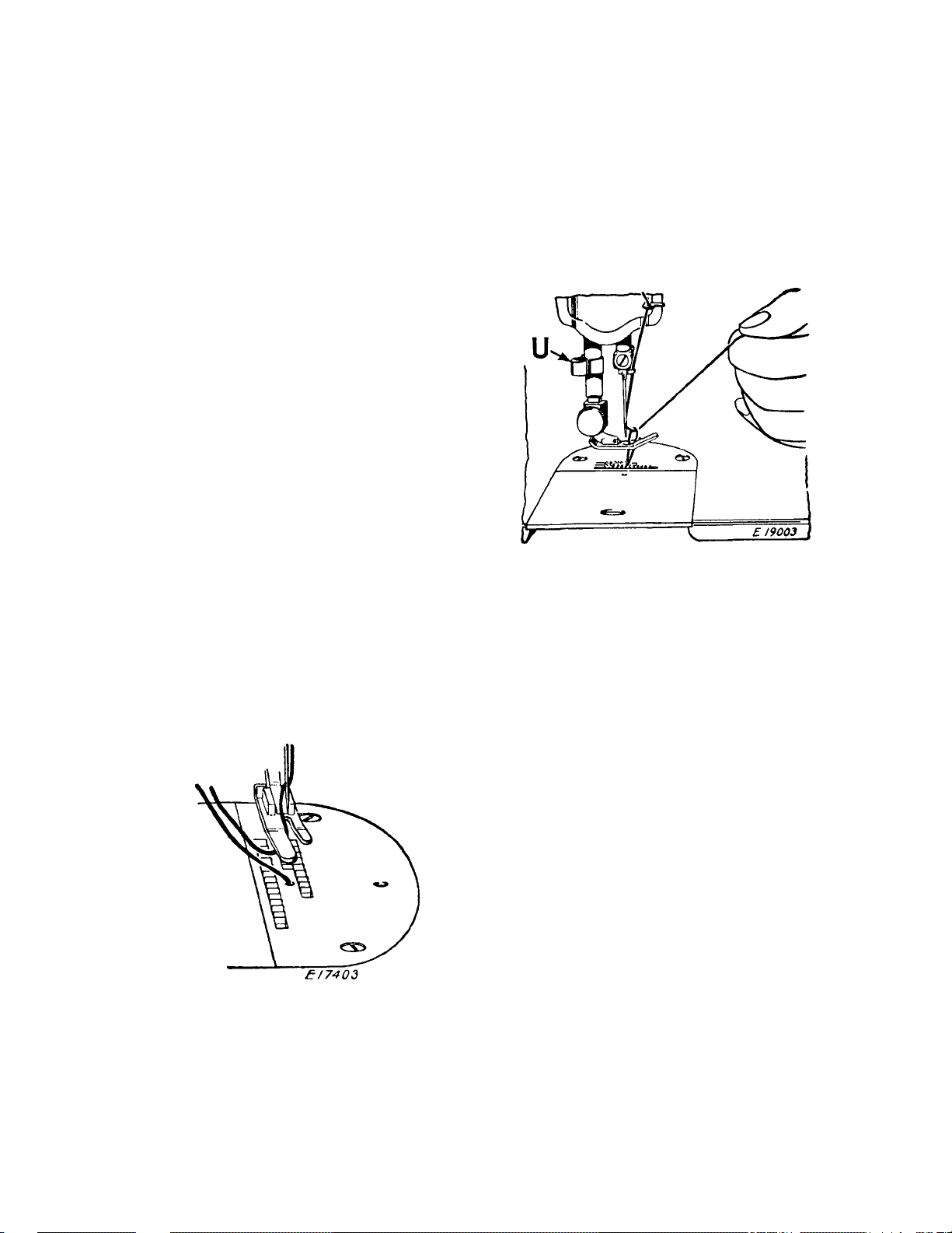
TO REMOVE THE WORK
Stop the machine with the thread take-up lever
5, Fig. 16 at its highest position. Raise the presser
foot, draw the fabric back and to the left, and sever
the threads on the thread cutter U, Fig. 16. Place
the ends of the threads under the presser foot, as
shown in Fig. 15.
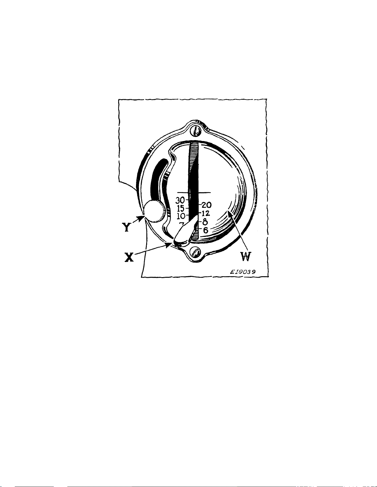
Page 20
18
TO REGULATE THE LENGTH OF STITCH
The machine is adjustable to make from 6 to 30
stitches per inch, as indicated by the numerals on
the stitch indicator plate
W.
Fig. 17. Showing Lever for Reversing Direction
OF Feed and Regulating Length of Stitch
The number of stitches to the inch that the ma
chine is set to make is indicated by the number
which is in line with the upper side of the stitch
regulating lever X.
To change the length of stitch, loosen the thumb
screw Y and move it to the bottom of the slot. Then
move the stitch regulating lever X until its upper
side is in line with the number of the desired length
of stitch. Now move the thumb screw Y until the
stitch regulating plate touches the lever X, then
tighten the thumb screw
Y.
The machine will now make the indicated number
of stitches to the inch in either a forward or reverse
direction, depending on whether the lever X is at
its lowest or highest position.
Page 21

19
TO REGULATE THE DIRECTION OF FEED
To feed the material from you, push down the
stitch regulating lever X Fig. 17 as far as it will go.
To feed the material toward you, raise the stitch
regulating lever X as high as it will go.
The direction of feeding can be reversed at any
point of a seam without removing the work from
the machine.
The reverse feed makes it easy to do 'Tack tack
ing” and to fasten the ends of seams.
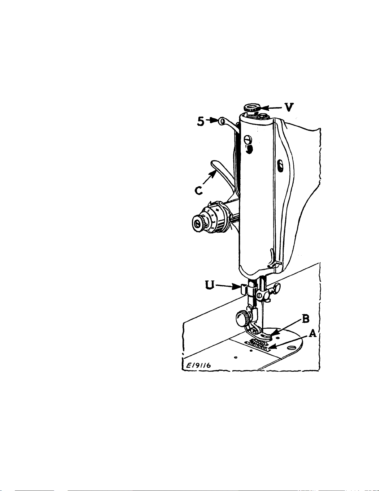
TO REGULATE PRESSURE ON
PRESSER FOOT
For ordinary sewing, the pressure of the presser
foot on the material seldom requires changing. Heavy
materials require more pressure than light weight
materials. The pressure should be only heavy enough
to prevent the material from rising with the needle
and to enable the feed to move the work along
evenly. To increase the pressure, turn the thumb
screw V, Fig. 16 clockwise or downward. To lighten
the pressure, turn the thumb screw so that it screws
upvrard.
SINGER Needles should be used
in SINGER Machines
These Needles and their Containers
are marked wi th the
Company’s Trade Mark "SIMANCO.*” i
Need I es in Containers marked
"FOR SINGER MACHINES”
are NOT SINGER made needles. 2
Page 22

20
THREAD TENSIONS
For ordinary stitching, the needle and bobbin
threads should be locked in the center of the thick
ness of the material, thus:
Fig. 18. Perfect Stitching
If the tension on the needle thread is too tight, or
if that on the bobbin thread is too loose, the needle
thread will lie straight along the upper surface of
the material, thus:
---
Enm
Fig. 19. Tight Needle Thread Tension
If the tension on the bobbin thread is too tight,
or if that on the needle thread is too loose, the bobbin
thread will lie straight along the under side of the
material, thus:
m.
E1I3I9
Fig. 20. Loose Needle Thread Tension
TO REGULATE THE
NEEDLE THREAD TENSION
The tension on the
needle thread can be
regulated only when
the presser foot is
down.
The numerals “0 to
9’’ on the dial C, Fig.
21 indicate the dif
ferent degrees of ten-
sion that can be
obtained. The num
bers do not denote the
size of thread or ounces
of tension.
Fig. 21. Needle Thread Tension
Page 23

21
When the tension has been correctly set for aver
age sewing, note the number at the indicator line Q,
so that the tension may be reset should it be altered
for special work or change in size of thread.
To increase the tension, turn the thumb screw A
gradually to the right (clockwise) until the required
tension is obtained. Each higher number denotes
increased tension.
To decrease the tension, turn the thumb screw
A gradually to the left (counter-clockwise) until the
required tension is obtained. Each lower number
denotes less tension.
TO REGULATE THE
BOBBIN THREAD TENSION
The tension on the bobbin thread is regulated by
the screw R, Fig. 11 in the tension spring on the
outside of the bobbin case. To increase the tension,
turn the screw R over to the right. To decrease
the tension, turn this screw over to the left.
When the tension on the bobbin thread has been
once properly adjusted, it is seldom necessary to
change it, as a correct stitch can usually be obtained
by varying the tension on the needle thread.
Page 24

22
TO DISASSEMBLE THE
NEEDLE THREAD TENSION
NOTE: The needle thread tension, Figs. 21
to 23 inclusive, is correctly adjusted at the fac
tory to produce the complete range of tensions
with one revolution of the thumb nut A,
There should be no necessity for removing or
taking this tension apart. However if, for any
reason, it becomes necessary to remove the
tension, proceed as follows:
Turn the thumb nut A, Fig. 22 away from you
(toward the left) until it stops at “0” on the num-
A B c s F
DF2
M P
Fig. 22, Needle Thread Tension Disassembled
bered dial C. Press in the dial to disengage the pin
B in the thumb nut and remove the thumb nut,
£190St
dial, stop washer D, tension spring F, indicator G,
the two tension discs H, thread guard plate L, and
the tension releasing pin J, as shown in Fig. 22. To
remove the pin J from the stud N, take off the face
plate and tilt it so that the pin will drop out.
Page 25

23
TO REASSEMBLE THE
NEEDLE THREAD TENSION
Replace the face plate, insert the tension releasing
pin in the stud, place the thread guard plate on the
Fig. 23. Reassembling and Replacing the Tension
stud, being sure that the lug M, Fig. 22 engages
the short recess P to prevent the plate from turn
ing on the stud. Next, place the two tension discs
H on the stud, having the flat thread-bearing sides
of the discs together. Replace the indicator G with
the large open side facing end of stud so that the
plus and minus signs will be readily seen from a
sewing position as shown in Fig. 23. Insert the ten
sion spring F in the indicator so that the first half
turn F2 of this spring will straddle the lower half of
the tension stud. Guide the stop washer D onto the
stud so that the extension S will be above the ten
sion stud as shown in Fig. 23.
NOTE; If the
spring and stop
washer are in cor
rect position, the
extension will clear
the first
halfcoil of the spring,
as shown in
Fig. 24.
Next place the
numbered dial on
the stud so that the
Fig. 24
£ /90*8
numeral 2 is oppo
Page 26

24
site the stop washer extension S, then push
the dial to compress the spring so that the
thumb nut can be turned onto the stud,
carefully guiding the pin in the thumb nut into
one of the holes in the numbered dial. Lower
the presser bar and turn the thumb nut
A to the
left until it stops at “0.” Thread the tension and
pull the thread through the tension discs to test the
amount of tension at the position. At this point
there should be a barely perceptible pull on the
thread to indicate that there is a minimum tension
which gradually increases with the turn of the thumb
nut to the right, providing a full range of tensions
from light to heavy within one revolution of the
thumb nut. If the pull is too strong for a minimum
tension, press in the numbered dial to disengage the
pin in the thumb nut from the dial and reset the pin
in one of the holes to the
left of the previous setting.
This resetting of the pin will produce less tension at
zero. On the other hand, should there be insufficient
tension at zero, press in the dial and reset the pin
in one of the holes to the right of the previous set
ting. Repeat this process until the desired minimum
tension is obtained.
If Correct Stitching is Not Obtained:
If the bobbin thread tension has been disturbed,
or a correct stitch cannot be obtained without a
very heavy or very light needle thread tension, then
the following procedure is recommended:
Using No. 50 thread in the needle and on the bob
bin, adjust the needle thread tension as instructed
above. Then turn the tension thumb nut to “4” and,
with two thicknesses of thin material in the machine,
adjust the bobbin thread tension, as instructed on
page 21, until the stitch is correctly locked in the
material as shown in Fig. 18.
A wide range of materials and threads can now
be accommodated without further adjustment of
the bobbin thread tension.
Page 27

25
TO OIL THE MACHINE
If the machine is used continuously, it should be
oiled daily. If moderately used, an occasional oiling
is sufficient.
Apply one drop of oil at each of the places indicated
by the unlettered arrows in Figs. 25 and 27 to 29.
Draw to the left the bed slide plate, and after
removing the lint and dust which may have accumu
lated (see instructions on pages 28, 29 and 30),
apply oil to the shuttle race A, Fig. 30. The slide
should then be closed.
Page 28

26
Loosen the thumb screw in the round cover plate
at the back of the machine, turn the plate upward
and fasten by tightening the screw. Turn the bal
ance wheel over toward you until the connecting
Fig. 26. Oiling Points at the Back of the Machine
rod Z, Fig. 26 is at its highest position. Then apply
a few drops of oil through the hole in the top of the
machine, to the wick which is retained in the cap
of the connecting rod, as shown in Fig. 26. Also
oil the other moving parts inside, turn the cover
nlate down and fasten it as before.
Page 29

27
Loosen the screw A2, Fig. 27
near the upper end of the face
plate, raise the plate and slip
it off over the head of the
screw. Apply one drop of oil
at each of the places indicated
by the unlettered arrows in
Fig. 27, then replace the face
plate and fasten it as before.
Fig. 27. End View
“Showing Oiling Points
Apply a drop of
oil at each of the
oil holes in the hand
driving attachment,
as shown by arrows
in Fig. 28.
Fig. 28. Oiling Points in
Hand Driving Attachment
Page 30

28
When the machine is used on a foot power stand,
to reach the parts underneath the bed of the ma
chine, press the belt shifter to the left and operate
£/9096
Fig. 29. Oiling Points in Base of Machine
the treadle meanwhile until the belt is released,
then turn the machine back on its hinges. Apply
one drop of oil at each of the places indicated by
arrows in Fig. 29.
Also lubricate each of the bearing points in the
stand.
Machine Working Heavily;
If the machine runs hard after standing idle for
some time, use a little kerosene in the oiling places,
run the machine rapidly, then wipe clean and oil.
To Clean the Stitch Forming Mechanism:
After considerable use, the stitch forming mechan
ism in the bed of the machine may become clogged
with lint and this may interfere with the perfect
operation of the machine.
Page 31

29
Occasionally remove the shuttle from the machine,
as instructed below and remove any lint, etc., which
has accumulated in the machine.
TO REMOVE THE SHUTTLE
Draw to the left the bed slide plate. Turn the
balance wheel over toward you until the needle is
Fig. 30. Showing Position of Shuttle for
Removal from Machine
at its highest point and the point of the shuttle is
at the position shown in Fig. 30.
Remove the bobbin case and bobbin. Take out
the thumb screw D, Fig. 30, also the spring
C, Fig. 30 and the shuttle race back B, Figs. 30
and 31. The shuttle A, Figs. 30 and 31 may now
be easily removed and the parts cleaned.
Page 32

30
TO REPLACE THE SHUTTLE
See that the needle is at its highest point. Replace
the shuttle with its point A in the position shown
£/9033
Fig. 31. Shuttle and Paets Removed from Machine
in Fig. 31, then replace the other parts in the order
illustrated in Fig. 31. Replace and tighten the
thumb screw D. Replace the bobbin and bobbin
case and close the bed slide plate.
Page 33

31
SEWING SUGGESTIONS
Breaking of Needles Might be Caused by;
(1) Improper Size of Needle for Thread and Material.
See page 7.
(2) Needle Bent.
(3) Pulling of Material when Stitching.
(4) Needle Striking Improperly Fastened Presser Foot
or Attachments.
(5) Crossing Too Thick Seams with Too Small a Needle.
Breaking of Needle Thread Might be Caused by:
(1) A Knot in the Thread.
(2) Improper Threading. See page 9.
(3) Upper Tension Too Tight. See page 20.
(4) Needle Set Incorrectly. See page 8.
(5) Needle Blunt or Bent.
(6) Thread Too Coarse for Needle. See page 7.
(7) Roughened Hole in Throat Plate.
(8) Improper Arrangement of Threads to Commence
Sewing. See page 15.
Breaking of Bobbin Thread Might be Caused by:
(1) Improper Threading of the Bobbin Case.
See page 13.
(2) Bobbin Thread Tension Too Tight. See page 21.
Skipping of Stitches Might be Caused by;
(1) Improper Setting of Needles. See page 8.
(2) Needle Blunt or Bent.
(3) Needle Too Small for Thread. See page 7.
Belt Tension:
The belt should be just tight enough to keep from
slipping. If too loose, remove the hook at one end,
shorten the belt and rejoin.
Free Instruction for using the machine is gladly
given at any SINGER Shop.
Page 34

32
DARNING OR EMBROIDERING
Turn the machine back on its hinges. Unscrew as
far as possible the thumb screw B, Fig. 32 which
is located in the lower end of the slot of the feed
A B
Fig. 32. Adjustment for Darning or Embroidering
lifting crank A, Fig. 32. The feed is thus rendered
inoperative and will not interfere with the free
movement of the work. Bring the machine forward
into place.
Move the stitch regulating lever X, Fig. 17 to
its neutral position in the center of the slot at the
front of the machine.
Remove the presser foot and let down the presser
bar lifter C, Fig. 16 to restore the tension on the
needle thread which is released when the lifter is raised.
Draw up the bobbin thread as instructed on
page 15.
Page 35

When darning
flat work, it is
advisable to use
embroidery
hoops to hold
the work.
Place the work
in the machine,
having the un
worn part near
the hole under
the needle. Com
mence the darn
ing by making a
line of stitches
across the hole a
little longer than
the width of the
hole. Continue ma
king parallel lines
33
K "'' I
-■'W:- i
Fig. 33. Darning in Process
of stitches across the
and forward and at
hole, moving the work backward
the same time gradually moving
the work side-
-r-.= -/-"v"i wise until the
hole is covered
Cf with lines of
; stitches running
".crj across the hole.
:g ? Then commence
; as before and
T ; move the work
, lengthwise of the
\ hole until the
stitches across
2 the hole are
V; completely cov-
ered and the
£!2M'-. darn is finished.
Fig. 34. Darning Finished
Page 36

34
When you have finished the darning or embroidery,
raise the presser bar lifter and replace the presser
foot. Turn the machine back on its hinges and move
the thumb screw B, Fig. 32 down to the bottom
of the slot of the feed lifting crank A, Fig. 32 and
make sure that the thumb screw is firmly tightened.
Bring the machine forward into place, return the
stitch regulating lever X, Fig. 17 to its original posi
tion and the machine is ready for regular stitching.
Stockings and socks, underwear, etc., can be
more conveniently darned on the machine with the
SINGER Darner which can be purchased at any
SINGER Shop or from any SINGER Salesman.
SINGER Needles should be used
in SINGER Machines
These Needles and their Containers
are marked with the
Company’s Trade Mark “SIMANCO.*” i
Needles in Containers marked
“FOR SINGER MACHINES”
are NOT SINGER made needles. 2
Page 37

35
INSTRUCTIONS
FOR USING
THE ATTACHMENTS
Page 38

36
THE FOOT HEMMER
The foot hemmer may be used for hemming the
edge of the material, making hemmed and felled
seams and for hemming and sewing on lace in one
operation.
e/bobff
Fig. 35. Foot Hemmer
To Attach the Foot Hemmer:
Raise the needle to its highest point, remove the
presser foot and attach the foot hemmer to the
presser bar in place of the presser foot.
Pull up the bobbin thread as instructed on page 15.
To Start the Hem at the Edge;
(1) Fold the edge of the material over about }/s inch
at the starting point for a distance of about
one inch.
(2) Place the material in the foot hemmer with the
folded edge at the back of the hemmer leading
at an angle to the right.
Page 39

37
(3) Draw the material toward you through the hem-
mer, at the same time folding the edge a second
time. Continue to draw the material through
the hemmer until the edge is just under the
needle.
Fig. 36. Hemming Edge of Material
(4) Place the needle and bobbin threads under the
foot hemmer, lower the hemmer and commence
to sew, assisting the starting of the hem by
slightly pulling the threads from the back while
sewing.
(5) Keep the mouth of the foot hemmer full to pro
duce a smooth, even hem.
Page 40

38
TO MAKE A HEMMED SEAM WITH THE
FOOT HEMMER
(1) When making this seam,
the garment must first be
fitted and the edge of the ma
terial trimmed, allowing for
about yg inch seam. Insert
the two edges of the material,
right sides together, in the
hemmer in the same manner
as a single hem as shown in
Fig. 37. If the material is
bulky, place the edge of the
Fig. 37
Making a Hemmed Seam
(First Operation)
upper piece of material about
ys inch to the left of the
edge of the under piece.
(2) The free edge of the hem
med seam may be stitched
flat to the garment, if
desired. To do this, open
the work out flat, wrong
side up, then insert the
hem in the scroll of the
hemmer, holding the edge
of the hem in position
while it is being stitched.
If the seam is stitched
flat to the garment, one
row of stitching is visible
on the right side.
Fig. 38
Making a Hemmed Seam
(Second Operation)
Page 41

39
TO MAKE A FELLED SEAM WITH THE
FOOT HEMMER
(1) Place the right
sides of the material to
gether, having the edge
of the upper piece about
3/8 iJich to the left of the
edge of the under piece»
Stitch the two pieces to
gether, using the hemmer
as a presser foot. Guide
both pieces by the pro
Fig. 39. Making a Felled Seam
(First Operation)
(2) Open the work
out flat, wrong side up,
and hem the free edge
of the seam, stitching it
flat to the garment as
jecting toe of the hem
mer, as shown in Fig. 39.
shown in Fig. 40.
F;g. 10. Making a Felled Seam
(Second Operation)
Page 42

40
TO НЕМ AND SEW ON LACE
IN ONE OPERATION
(1) Start the hem in the regular way.
(2) Hold the hem in position with the needle.
Fig. 41. Hemming and Sewing on Lace
(3) Raise the presser bar and insert the edge of the
lace in the slot of the hemmer and back under
the hemmer.
(4) Lower the presser bar and commence sewing,
catching the edge of the lace with the needle.
(5) Guide the hem with the right hand and the lace
with the left, being careful not to stretch the
lace as it enters the hemmer.
Page 43

41
ADJUSTABLE HEMMER
To Make Hems from 3/16 to 15/16 Inch Wide
(1) Attach the adjustable hemmer to the presser bar
in place of the presser foot.
(2) Pull up the bobbin thread, as instructed on page 15.
Fig. 42. Showing How Adjustable Hemmer is Used
FOR Making Hems up to 15/16 Inch Wide
(3) Loosen the thumb screw on the hemmer and move
the scale until the pointer registers with the
number of the desired width of hem, No. 1 indi
cating the narrowest hem and No. 8, the widest,
then tighten the thumb screw.
(4) Place the cloth in the hemmer and draw it back
and forth until the hem is formed, as shown
in Fig. 42.
(5) Draw the end of the hem back under the needle,
lower the presser bar and commence to sew.
(6) Guide sufficient cloth into the hemmer to turn the
hem properly.
Page 44

42
ADJUSTABLE HEMMER
To Make Hems Wider than 15/16 Inch
(1) Loosen the thumb screw on the hemmer, move the
scale to the right as far as it will go, then swing
it toward you, as shown in Fig. 43, and tighten
the thumb screw.
(2) Fold and crease the desired width of hem.
Fig. 43. Showing How Adjustable Hemmer is Used
FOR Making Hems Wider than 15/16 Inch
(3) Place the fold under the extension at the right
of the hemmer and the edge into the folder, as
shown in Fig. 43.
(4) Draw the end of the hem back under the needle,
lower the presser bar and commence to sew.
(5) Guide the cloth to keep the hem flat.
Page 45

43
MULTIPLE SLOTTED BINDER
This multiple slotted Binder will apply unfolded
bias binding ^inch in width and commercial folded
binding in sizes if 2y 3) 4 and 5 to the seams or to
the edges of garments. These sizes of folded binding
are 34, /4, A and inch in width, respectively,
and are fed through slots of corresponding sizes in
the binder scroll. See Fig. 44. Binding may be
purchased in a variety of materials and colors.
For convenience in determining the correct width
of unfolded binding inch), this measurement
is marked on the Binder, as shown in Fig. 44.
The two upright guide pins shown in Fig. 44 elim
inate manual guiding of the binding.
ADJUSTING
LUG
SCROLL FOR
UNFOLDED
OUTSIDE
SLOTS FOR
DIFFERENT
WIDTHS OF
FOLDED
BINDING
CENTER SLOT
OF SCROLL
Fig. 44. Multiple Slotted Binder 160359
EDGE GUIDE
FOR PIPING
ONLY
BINDING
B/BI6S
The wide range of bindings that can be applied
with this Binder makes it useful for a large variety
of work. It will be found particularly advantageous
for making children’s wear, lingerie, summer dresses,
and other dainty articles which call for the nar
rower bindings.
Page 46

44
As two different widths of binding of contrasting
color can be fed through the Binder at the same
time, attractive binding and piping effects can be
produced in one operation.
TO ATTACH THE BINDER
Raise the needle to its highest position, then at
tach the Binder to the presser bar in place of the
presser foot.
See that the needle enters the center of the
needle hole.
TO INSERT THE BINDING
IN THE BINDER
Cut all binding to a long point
to the left, as shown in Fig. 45.
Folded Bias Binding must be
inserted in the slot or slots of cor
responding sizes. See
Fig. 48.
Unfolded or Raw Edge Bias
Binding must be inserted in the
open end of the scroll. See
Fig. 46.
After inserting the pointed end of the binding in
the Binder, push it through until the full width of
the binding is under the needle.
Guide the binding by means of the two upright
pins, as shown in Figs. 46 and 48.
Page 47

45
TO INSERT THE GARMENT
IN THE BINDER
Place the edge to be bound as far to the right as
it will go in the center slot of the scroll, as shown in
Fig. 46, and draw it back under the binder foot.
Fig. 46. Binding with Unfolded Binding
Lower the Binder by means of the presser foot
lifter, and commence to sew. Keep the material
well within the center slot of the scroll so that the
edge will be caught in the binding.
TO ADJUST THE BINDER
To bring the inner edge of the binding closer to
the stitching, move the scroll C2, Fig. 46 to the
right by means of the lug B2, Fig. 46. This is
the usual adjustment when binding straight edges.
When binding curves, move the scroll to the left
to bring the inner edge of the binding farther from
the stitching and allow for the sweep of the curve.
Page 48

46
PIPED EDGE
To produce a piped edge on garments, move the
lug B2, Fig. 47 to the left to bring the stitching
about midway of the folded binding.
Fig. 47
Position of Garment and Binding when Piping Edges
Crease the raw edges of the garment toward the
wrong side about 3^ inch, and insert the folded
edge, raw edges uppermost, into the edge guide on
the Binder, and beneath the binding.
When stitched, both sides of the garment will be
finished, and the right side will show the piped edge.
Page 49

47
PIPING AND BINDING IN
ONE OPERATION
A garment can be piped and bound in one opera^
tion, as shown in Fig. 48.
Fig. 48. Piping and Binding in One Operation
IMPORTANT : When piping and binding at the
same time, as shown above, insert the narrow width
of binding first in its slot, then insert the wider
width in its slot. Two consecutive widths should
not be used at the same time. That is, if No. 1
is used, the wider binding should not be smaller than
No. 3 . If No. 2 is used, the wider binding should
be not less than No. 4. Never use Nos. 1 and 2,
or 2 and 3, etc., together.
Use the upright guide pins to guide the wider of
the two widths of binding, as shown in Fig. 48.
Page 50

48
TO BIND OUTSIDE CURVES
Allow the edge to be bound to pass freely through
the scroll without crowding against the scroll wall.
The material must be guided from the back of the
Binder and to the left, permitting unfinished edges
to swing naturally into the scroll of the Binder.
Fig. 49. Binding an Outside Curve
Never pull the binding while it is being fed through
the Binder, as this may stretch the binding, making
it too narrow to stitch or to turn in the edges.
When binding curves, turn the material only as
fast as the machine sews.
Do not push the material in too fast as this will
pucker the edge.
Do not stretch the material as this will distort
the edge so that the curve will not have the proper
shape when finished.
If the stitching does not catch the edge of the
binding, adjust the scroll slightly to the left.
TO BIND INSIDE CURVES
When binding an inside curve, straighten out the
edge of the material while feeding it into the Binder,
being careful not to stretch the material.
Soft materials like batiste or crepe de chine require
a row of stitching added close to the edge of the
curve before binding.
Page 51

49
TO APPLY FRENCH FOLDS
TO CURVES
Place the material under the Binder and stitch
the binding onto the face of the material, as shown
in Fig. 50.
Fig. 50. Applying a French Fold
For guidance in applying the rows of French folds,
mark the material with a line of basting stitches
or with chalk or pencil.
Page 52

50
THE EDGE-STITCHER
This attachment should be used when the stitch
ing must be kept accurately on the extreme edge of
the material. It is also useful for sewing together
laces, insertions and embroideries, sewing in position
hemmed or folded edges, piping or sewing flat braid
to a garment.
To Adjust the
Edge-Stitcher
Fasten this attachment to
the presser bar in place of
the presser foot.
See that the needle enters
the center of the'needle hole.
i
The distance from the line
of stitching to the edge of
the material in the slots is
regulated by moving the lug
D2, Fig. 51 to the right or
left.
The Edge-Stitcher
Fig. 51
To Sew Lace Together:
(1) Insert one of the laces in slot 1 of the edge stitcher
and the other in slot 4, Fig. 51.
(2) Adjust the lug D2 until the edges to be joined
are caught by the stitching.
(3) Slightly overlap the edges of the lace while stitch
ing to keep them against the ends of the slots.
^4) Loosen both thread tensions to avoid puckering
of fine lace.
Page 53

51
Fig. 52. Sewing Lace Together
To Insert Lace or Ribbon:
(1) Fold the edge of the material to which the lace
or ribbon is to be sewn and insert it in the slot 1
of the edge-stitcher.
(2) Insert the lace or ribbon in the slot 4 of the edge-
stitcher and proceed to sew.
(3) Cut away the surplus folded material close to
the stitching.
Fig. 53. Setting in Lace Insertion
Page 54

To Pipe with the
Edge-Stitcher
(1) Cut the piping bias and
twice the width of the
slot 3 so that it can be
folded once.
(2) Insert the piping with its
folded edge to the left
in slot 3 and the edge
52
to be piped in slot 4,
Fig. 51.
Piping with Edge-Stitcher
Fig. 54
To Apply Folded Bias Tape or Military Braid
(1) Place the garment under the edge-stitcher and the
tape in slot 1 or 4, Fig. 51.
Fig. 55. Applying Bias Folded Tape
(2) To make square corners, sew to the turning point,
remove the tape from the attachment, form the
corner by hand, replace the tape and continue
stitching.
(3) To space two or more parallel rows, mark the
material with a guide line, using a crease, chalk
or basting thread.
Page 55

To Stitch a Wide Hem
(1) A wide hem may be
stitched evenly on
sheets, pillow slips,
etc., with the edge-
Stitcher after the
hem has been
measured and the
edge turned.
(2) Insert the edge in slot
5, Fig. 51, and ad
just the lug D2 to
stitch as close to
the edge as desired.
53
Fig. 56.
Making a Wide Hem
To Make a French Seam
Fig. 57.
Making a French Seam
(Second Operation)
(1) To make a uniform
width French seam,
insert the two edges
to be joined, wrong
sides together, in
slot 1 or 2 Fig. 51
and stitch close
to the edge.
(2) Fold both right sides
together and insert
the back of the
seam in the slot 1
and stitch, allow
ing just enough
margin to conceal
the raw edges.
Page 56

54
To Tuck with the Edge-Stitcher
The maximum width of tuck that can be made
with the edge-stitcher is 3^ inch.
Fig. 58. Tucking with the Edge-Stitcher
(1) Fold and crease the material for the desired width
of tuck.
(2) For succeeding tucks, fold the material the de
sired distance from the previous tuck, running
the fold lengthwise over a straight edge, then
crease the folds.
(3) Insert the creased folds in the slot 1 and adjust
the edge-stitcher to the right or left for the de
sired width of tuck. Use a light tension, short
stitch and fine thread and needle.
Page 57

55
GATHERING FOOT
To Shirr with the Gathering Foot
(1) Fasten the Gathering Foot to the presser bar in
place of the presser foot.
Fig. 59. Shirring with the Gathering Foot
(2) Place the material under the Gathering Foot and
stitch in the usual way.
(3) The fullness of the shirring or amount of gather
ing is regulated by the length of stitch. A longer
stitch increases the fullness of the gathers.
Page 58

56
PRINCIPAL PARTS OF THE RÜFFLER
Fig. 6ü. Principal Parts of the Rüffler
A—Foot—attaches ruffler to the presser bar.
B—Fork Arm—straddles the needle clamp.
C—Adjusting Screw—regulates fullness of the gathers.
D—Projection—engages the slots in adjusting lever.
E—Adjusting Lever—sets the ruffler for gathering or
for making a plait once at every six stitches or once
every twelve stitches as desired; also for disengag
ing the ruffler, when either plaiting or gathering
is not desired.
F—Adjusting Finger—regulates the width or size
of the plaits.
G—Separator Guide—contains slots into which
the edge of the material is placed to keep the
heading of the ruffle even; also for separating
the material to be ruffled from the material to
which the ruffle is to be attached.
H—Ruffling Blade—pushes the material in plaits
up to the needle.
J—Separator Blade—prevents the teeth of the
ruffling blade coming into concact with the
feed of the machine or the material to which
ruffle or plaiting is to be applied.
Page 59

57
TO ATTACH THE RUFFLER
(1) Raise the needle to its highest point.
(2) Loosen the presser foot thumb screw and attach
the ruffler to the presser bar in place of the
presser foot, at the same time placing the fork
arm B astride the needle clamp.
(3) See that the needle enters the center of the needle
hole in the ruffler.
Fig. 61. Gathering with the Ruffler
TO ADJUST THE RUFFLER FOR GATHERING
(1) Swing the adjusting finger F away from the needle.
(2) Raise the adjusting lever E and move it until the
projection D can be entered in the slot
marked
O
O
£/00a9X
Fig. 62.
Correct Position for Material to be Ruffled
MATeR/AL
(3) Insert the material to be ruffled between the two
blue blades Line 2, Fig. 62.
(4) Draw the material slightly back of the needle,
lower the presser bar and commence to sew.
(5) For fine gathering, turn the adjusting screw C
upward and shorten the stitch.
(6) For full gathering, turn the adjusting screw C
downward and lengthen the stitch.
Page 60

58
To Make a RufHe and Sew it to a Garment
in One Operation
(1) Insert the material to be ruffled between the two
blue blades Line 2, Fig. 63.
Fig. 64
Making a Ruffle and Attaching it in One Operation
(2) Place the material to which the ruffle is to be
attached under the separator blade
Line 1, Fig. 63.
(3) Proceed the same as for plain gathering.
Page 61

59
To Make a RufHe and Attach it with a
Facing in One Operation
(1) Insert the material to be ruffled between the two
blue blades Line 2, Fig. 65.
^RUFFLING MA TERIA^^
GARMENT^*
EIB090A
Fig. 65. Correct Positions for the Materials
(2) Place the material to which the ruffle is to be at
tached under the separator blade Line 1, Fig. 65.
(3) Place the facing material over the upper blue
blade Line 4, Fig. 65.
Fig. 66. Making a Ruffle and Attaching
IT WITH A Facing in One Operation
(4) If the facing is to be on the right side of the gar
ment, place the wrong sides of the garment
and ruffle together.
(5) If the facing is to be on the wrong side, place the
right sides of the garment and ruffle together.
Page 62

60
To Pipe a Ruffle:
Cl) Insert the material to be ruffled between the two
blue blades Line 3, Fig. 67. This material must
not exceed inches in width.
Fig. 67. Correct Positions for the Materials
(2) The piping material is usually cut on the bias and
it should be about 34 inch wide when folded in
the center. Place the piping material in the
ruffler, following Line 5, Fig. 67 with the folded
edge of the piping to the right.
Fig. 68. Piping a Ruffle
(3) Fold the edge of the material to which the piping
and ruffling are to be attached and insert it in
the rufffer, following Line 6, Fig. 67.
Page 63

61
To Adjust the Ruffler for Plaiting:
(1) Raise the adjusting lever E and move it until the
projection D can be entered in the slot marked
“6.” The ruffler will then plait once every six
stitches. To plait once every 12 stitches, have
the projection D enter the slot “12’* in the
adjusting lever E.
Fig. 69. Plaiting with the Ruffler
(2) Insert the material to be plaited between the two
blue blades Line 2, Fig. 70.
MATERIAL
Fig. 70. Correct Position for the Material
(3) To increase the width of plait, move the adjust
ing finger F back toward the needle and turn
the adjusting screw C downward. To make a
smaller plait, turn the adjusting screw C up
ward. The distance between plaits is regulated
by the length of stitch.
Page 64

62
To Adjust the Ruffler for Group Plaiting;
(1) To make the space between the groups of plaits,
raise the adjusting lever E and move it until
the projection D can be entered in the small
slot indicated by the star on the adjusting lever
E. The ruffler will then stop plaiting and plain
stitching will be made.
Fig. 71. Group Plaiting with the Ruffler
(2) When the desired space is made, set the projec
tion D in either of the slots 6 or 12.
(3) Insert the material to be plaited between the two
blue blades Line 2, Fig. 72.
MATERIAL
Fig. 72. Correct Position for the Material
TO OIL THE RUFFLER
Occasionally apply a drop of oil to the working
parts of the ruffler at each of the places indicated
in Fig. 71.
Page 65

63
The SINGER Universal Threader and
Seam Ripper
Makes Threading Easy
£¡3004
This useful little accessory enables you to thread a
hand sewing needle or a machine needle without eyestrain. As shown on the following page, it also serves
Threading
Needle
WITH
SINGER
Needle
Threader
etSBJB
as a seam ripper with a blade set at just the right
angle for quickly picking out stitches. Both ends
fold into the handle like a jack-knife. It is sold by
all SINGER Shops at a reasonable price.
Page 66

64
The SINGER Material Gripper
Taking out stitches is no longer a tedious job when
you use the SINGER Seam Ripper and Material
Opening Seam with
SINGER Seam Ripper
Material Gripper Holds Cloth
Gripper, as shown above. The gripper acts as a
third hand, holding your material while you pin,
sew or rip. It is sold by all SINGER Shops at a
reasonable price.
Page 67

THE I MPO RTA NCE OF US ING
SINGER*
NEEDL ES FOR YO UR
SEWI NG MACH INE
You will obtain the best stitchm g
resu lts fro m your sewing machin e
if it is fitte d with
a SINGER
Need le.
SINGER
chase d from any
or
SINGER
SINGER
in the
Need les can be pur
SINGER
Sale sman .
Need les are containe d
SINGER
Gree n Needle
Shop
Pack et with the famo us red letter
"S" upon it .
Page 68

FOR YOUR PROTECTI
Singer sells its machines onl
SINGER Sewing Centers, identifi
\
i
i
CO
yj c
Red “S” on the window, and nevei
department stores or other outlets.
When your machine needs servi«
your Singer Sewing Center anc
of warranted SINGER parts and
Check local address in teiephon
tory under name of
SINGER SEWING MACHINE CO>
o S
c
O S
oo
 Loading...