

Page 1

OPERATOR
INSTRUCTIONS
SINGER
MODEL
1501
INTELLIGENT TERMINAL
SINGER
BUSINESS
MACHINES
Page 2

OPERATOR
INSTRUCTIONS
SINGER
INTELLIGENT
MODEL
TERMINAL
1501
22-6504-01
AUGUST
1975
SINGE;R
BUSINESS
.
PRIN~£D
MACHINES
IN
;U.S.A.
Page 3

REVISION
RECORD
Edition
Letter Suffix
Description
None
"
00
Original
Printing
August
-
1975
"
,
"
"
Operator Instructions
, .
8/75
Page 4

CONTENTS
SECTION
1
2
3
INTRODUCTION
GENERAL
DESCRIPTION
OPERATOR
OPERATING
3-1.
3-2.
3-3.
3-4.
3-5.
. . . .
CONTROL
PROCEDURES
Scope
Inspection of the
Application of
Loading a Tape
Normal
3-6. Unloading a
3-7.
3-8.
Removal
Error or
pANELS
..
of
this
Operation
Tape
of
Power
Check
...•
Section
Terminal
Power
...
Cartridge .
•...
Cartridge
Conditions
PAGE
iv
1-1
2-1
3-1
3-1
3-1
3-1
3-1
3-3
3~3
3-4
3-4
4
Tape
3-9.
OPERATOR
MAINTENANCE
Errors
4-1. General Information
4-2.
4-3.
4-4.
Tape
Leader
Freeing a
Drjve Cleaning
Replacement
Jammed
• . • . •
Loader
i
3-6
4-1
4-1
4-1
4-5
4-9
Page 5

CONTENTS
ILLUSTRATIONS
FIGURE
1-1
2-1
2-2
2-3
2-4
2-5
2-6
4-1
4-2
4-3
4-4
4-5
4-6
4-7
Singer
Location of the
Location of the
Keyboard
Controls
Tape
Tape
Releasing the
Seri
Removing
Cleaning the
Removing
Inserting the Leader Eyelet in the Clip
Connecting the
Model
Cartridge •
Cartridge with Cartridge
es
1500
1501
Layout
on
the
Tape
the
Leader
Capstan
the
Leader
Intelligent
Power
Switch
. . .
Tape
.
.
Loader
Dri
Leader
On/Uff
Well
. · .
Drive.
.
.
·
Retainer
ve
•
· · · ·
Eyelet •
After
Clip
From
Eyelet to the Post
Terminal. • • . • • . • • •
Switch
. .
Cap
Lock
Leader
the Clip
· · ·
.
· · ·
Removal
·
.
·
· ·
·
Channel
Channel
on
the
· · ·
· · · ·
· ·
.
· · ·
.
· · · ·
· · · ·
Clip.
..
·
· · ·
·
·
· · ·
· · ·
·
·
·
PAGE
1-1
2-2
2-2
2-2
2-3
2-4
2-4
4-2
4-3
~-~
4-4
4-5
4-6
4-7
4-8
4-9
4-10
Moving
Leader
Fre~ing
the Clip into the
Shown
a
Jammed
in
Tape
Loader
Path
Channel
·
ii
. .
·
·
· · · · ·
4-7
4-8
4-9
Page 6

CONTENTS
TABLES
TABLE
3-1
Error or
Check
Conditions
••••••••••••.•.••.
PAGE
3-5
iii
Page 7

This
manual
Intelligent
provides the operating instructions for the
Terminal.
It
includes the following information:
Model
INTRODUCTION
1501
SECTION 1 GENERAL
of
how
the
equipment
and
identifies
SECTION 2 OPERATOR
and
appearance of
what
each
control
SECTION 3 OPERATING
step-by-step procedures required to operate the
section
operating
conditions
SECTION 4 OPERATOR
be
provided in
does
programs.
performed
not include instructions
and
this
DESCRIPTION,
functions
all
major
CONTROL
all
does
PROCEDURES.
It
the
checks
MAINTENANCE.
by
the operator
section.
which
from
parts of the equipment.
PANELS.
operator controls.
when
it
is
does,
to
however,
be
and
provides a
the viewpoint of
This section
operated.
Included in
that
include a
made
to correct
Routine maintenance functions to
the procedures to
It
also
this
are provided with the
brief
machine.
them.
description
an
operator
shows
list
the location
briefly
section are the
perform
describes
This
of
error
them
are
iv
Page 8

SECTION
1
The
Singer
pact desk-top
houses a
efficient
can
serve
program
functions
program
Model
keyboard
1501
unit
that
slmi1ar to
Intelligent
provides
fi11-in-the-b1ank type
as
either
that
controls operation of the
can
be
tapes
and
input or output
obtained
by
following the
that
simply loading
Operator controls other than the
program
errors
in the keyboard
load,
is
and
both visual
program
on
section.
interrupt
the display screen
Terminal
all
the functions
shown
GENERAL
in figure
of
a mini-computer.
DESCRIPTION
1-1
is a com-
of a typewriter, a display screen
of
data
entry,
units,
1501.
instructions
keyboard
include power-on, system
two
tape drives
and a memory
that
Various, wide-ranging
different
given
pre-recorded
by
the
program.
that
stores the
switches. Notification of data entry
and
audible through a speaker
It
for
reset,
Figure 1-1. Singer
Model
1-1
1501
Intelligent
Terminal
Page 9

SECTION
2
The
Model
aside
the table
a.
b.
c.
d.
from
The
power
in figure 2-1.
A
well
INTERRUPT
figure 2-2.
The
keyboard,
supplemented
in figure 2-3.
On
each
the supply
which
these controls
1501
Intelligent
the keyboard.
below,
beneath the display screen houses the
;s
and
their
on/off switch
and
the
which
by
the addition of
tape drive, there
and
take-up
used
to lock the tape cartridge in place.
is
Terminal
The
function of these controls
location
is
SYSTEM
shown
RESET
is
similar in layout to
is a manual
reels.
in figure 2-4.
has
is
located
switches,
some
There
relatively
as
follows:
on
the
which
special purpose keys,
rewind
is
also a cartridge lock
OPERATOR
few
operator controls
right
side panel, as
PROGRAM
are
shown
that
of a typewriter
switch located
The
CONTROL
is
described in
LOAD/PROGRAM
in
location of
PANELS
shown
is
shown
between
lever,
Control
Keyboard
PROGRAM
PROGRAM
and
Rewind
Power
LOAD
INTERRUPT
SYSTEM
Button
on/off
Switch
RESET
Switch
Switch
Function
Data
entry
mined
Enables operator to load a
the tape in drive 2 (Switch forward for
program
Used
when
programs
Rewinds
Controls
up
for
and
various functions
by
program
load)
called for
tape into cartridge
AC
power
power
on)
by
to the
program
specific
1501
(Switch·
deter-
from
2-1
Page 10

OPERATOR
CONTROL
PANELS
Figure 2-1. Location of the
On/Off
Switch
Power
Figure 2-2. Location of the
Switch
Well
Figure 2-3.
Keyboard
2-2
Layout
Page 11

OPERATOR
CONTROL
PANELS
Figure 2-4. Controls
Operation of the
tape
cartridges.
100
contains
feet
a storage device
clear
outer case
CARTRIDGE
LOCK'LEVER
Model
1501
This snap-in
of
computer
used
with
fully
encloses the inner tape
REWIND
BUTTON
Intelligent
cartridge,
grade tape
all
Series
on
the
Tape
Drive
Terminal requires handling of the
which
on
1500
is
shown
in figure 2-5,
a floating inner
Intelligent
Terminals. A
reel,
reel.
and
is
located
the write pin
tape cannot
on
the IIwrite-enable
It
the tape
leader eyelet
is
Cartridge caps are supplied with
on
the
bottom
is
important
loaded.
the outer case
is
inserted into the position
be
written on.
of the
li
position.
that
is
loaded or the
must
be
is
a two-position hole for the write pin.
If
the write pin
cartridge,
the tape
the tape
be
fully
cartridge
in the position
each
rewound
removed
shown
cartridge
vibrating out of position during shipping.
it
off
with
bottom
rewind
fingertips.
side of the tape
loose tapes.
To
cartridge.
(See
figure 2-6.)
install
2-3
a cap,
Turn
on
is
may
be
from
in figure
To
push
the
cap
If
top of the
cartridge,
the
inserted into the position
written on;
this
is
called
within the cartridge before
the tape drive.
2-5
before the tape
to prevent the
remove
cap
the cap, simply
into place
in direction
The
eyelet
on
the
of
arrow to
tape
from
pry
Page 12

OPERATOR
CONTROL
PANELS
Figure 2-5.
Tape
Cartridge
Figure 2-6.
Tape
Cartridge with Cartridge
2-4
Cap
Page 13

SECTION
3
3-1.
3-2.
OPERATING
SCOPE
This section contains the procedures for operating the
Intelligent
further operating instructions.
by
this
you;
to explain the procedure to you.
INSPECTION
Inspect the terminal before using,
a.
b.
OF
THIS
SECTION.
Terminal
an
operator
section.
ask
your supervisor, sales engineer, or
Make
sure
place correctly.
Check
cables
when
Do
OF
THE
that
to see
and
plugs are properly connected.
up
to the point
errors or malfunctions occur are also included in
not attempt to perform
TERMINAL.
I/O
if
cabling
the
power
is
cord
at
which
Steps to
as
follows:
connected
is
properly
be
any
the
taken
step
field
and
terminator
plugged
program
and
that
service representative
Model
checks
is
in
1501
provides
to
not clear to
(if
and
any
PROCEDURES
be
made
any)
is
in
other
3-3.
3-4.
c.
Make
sure
that
the cooling airways are not blocked.
APPLICATION
a.
Turn
located
b.
Listen for indication
LOADING A TAPE
Always
tape, observe the following instructions
a. After
cover,
lever to the unlock
position.
OF
the
power
on
load the
opening
move
POWER.
on/off switch to the
the
right
CARTRIDGE.
first
the access
the locking
side of the unit near the back.
that
program
tape cartridge
the
fan
on
(up)
position.
is
operating properly.
on
tape drive
and
photographs:
The
2.
switch
To
load a
is
3-1
Page 14

b.
Lift
the loader.
called the cartridge
tion position.
c.
Insert
into tape drive
that
pin
the tape cartridge
the position of write
is
correct.
OPERATING
Thi
sis
inser-
2.
Check
PROCEDURES
Push
down
on
d.
with the tape cartridge
inserted.
Move
e.
the locking lever to
the lock position,
close the access cover.
the loader
and
3-2
Page 15

f.
g.
Locate
cover.
Move
tape,
OPERATING
PROCEDURES
the well beneath the visual display,
the
PROGRAM
and
close the access cover.
LOAD
switch
forward
to load the
and
lift
the
program
well
from
access
the
3-5.
NORMAL
After the
. tions appear
task
described in the following paragraphs.
3-6.
UNLOADING A TAPE
Unload
a.
b.
OPERATION.
program
is
completed; then
has
on
the display screen.
CARTRIDGE.
a tape cartridge
Open
the access cover and,
if
tape
is
not already
rewound
cartridge~
into the tape
push
button.
Move
th~
locking lever to
the
unlock
position.
been
the
loaded
unload
as
follows:
rewind
as a result
Follow
the tapes
of step (g) above, instruc-
these instructions until the
and
turn
off
the
machine
as
c.
Lift
the loader
3-3
Page 16

d.
Remove
Push
e.
tape cartridge
OPERATING
the tape cartridge.
down
the loader with
removed.
PROCEDURES
3-7.
3-8.
f.
Keep
the locking lever in
unlock
the
leader in place,
the access cover.
REMOVAL
a.
b.
ERROR
There
lems
Terminal.
be
OF
Turn
maintenance procedures.
taken.
the
is
located
Refer to Section 4 of
OR
CHECK
are several steps
that
position to
POWER.
power
on
CONDITIONS
occur during
Table
3-1
keep
and
close
on/off switch to the
the
right
lists
side
this
that
normal
some
panel
manual
an
operator
operation of the
of these
off
(down)
near the back.
and
perform
can
take to correct
Model
problems
position.
all
necessary operator
1501
and
the action
The
minor
Intelligent
switch
prob-
that
can
3-4
Page 17

OPERATING
PROCEDURES
Symptom
Cooling
rotating
lights
dri
Line
ves
on
fuse
fan
and
tape
blows
not
continually
Program
does
load
Burning
odor
Failure during
program
no
not
Table 3-1. Error or
Possible
1.
AC
line fuse
2.
AC
line
3.
AC
power
switch not
1.
Wrong
2.
Internal defect
1.
Tape
cartridge
Cause
cord loose
on/off
on
size fuse
installed
improperly
2.
PROGRAM
LOAD
defective
Burned
Component
Undetermined
Check
blown
switch
Conditions
Action to
Replace
Check
Turn
switch
Check
fuse.
line
fuse rating
be
cord.
on.
Taken
Call service representative.
Check
Tape
Loading
procedure.
Retry
Turn
PROGRAM
power
off
LOAD
switch
and
call
service representative
Retry
program
Display
Read
is
and/or write
errors
Leader
has
returning to
"home"
Tape
position
runaway
blank
trouble
Program
did not
load
Dirty read
1 •
2.
Dirty write
Dirty capstan
1 •
2. Faulty leader
Broken
1 •
2.
Broken
head
head
leader
tape
Retry
Follow
under
Clean
Replace
Follow
tape
runaway
program
load
directions
read/write errors.
capstan.
leader.
directions
under
3-5
Page 18

OPERATING
PROCEDURES
3-9.
TAPE
Tape
error
depending
ERRORS.
errors
may
occur
if
preventive maintenance
occurs, the tape read or write operation
on
the type of
error.
following:
Tape
Runaway.
If
both tape
off
immediately. There are
recommended
a.
If
the leader breaks, a tape
reels
that
ever spin uncontrollably
two
the
entire
program
using the procedure in Section 4 of
b.
If
the tape breaks, a tape
and
refer
this
to the procedure for freeing a
manual.
Read/Write Errors.
This type of
while loading a
of the tape drive.
be
reloaded
For
read/write
completed
be
determined. Depressing the
after
and
error
is
accompanied
program
The
the cause of the
errors
later
with data tapes, the current
reattempted.
tape, depress the
program
The
two
major
at
possible causes.
be
reattempted.
runaway
occurs.
this
runaway
by
occurs.
an
error
red
tape, or the
error
The
ERROR
is
determined
cause of the read/write
key
will quiet the
is
inadequate.
may
have
to
error
classes are the
high speeds, turn
In
all
cases
Replace
the leader,
manual.
Replace
jammed
tone.
rewind
copy
of the
the tape
loader in Section 4 of
If
read
button in the middle
program
and
program
error
If
a tape
be
aborted,
power
it
is
cartridge,
error
occurs
tape,
corrected.
should
be
error
must
tone.
may
Possible causes of read/write
a.
On
a tape write operation, the write pin
cartridge position.
b.
Dirt
on
the read/write heads, caused
maintenance.
c.
d.
Wrinkled
The
tape.
leader threading
was
tape guides.
errors
include the following:
was
not in the
by
inadequate preventive
bottom
not aligned in the proper grooves of the
3-6
Page 19

The
corrective action to
If
a.
b.
c.
unable to write
It
must
operation.
Check
leader
Section 4 of
Follow
if
be
the leader threading path
if
necessary
the tape drive cleaning procedure in Section 4 of
solutions (a)
in the
this
OPERATING
be
taken for read/write
on
a tape,
bottom
manual.
and
position
by
following the leader replacement procedure in
(b)
above
PROCEDURES
check
the position of the write pin.
on
the
cartridge.
and
inspect the leader. Replace the
do
not apply.
errors
is
as follows:
Retry
this
this
manual
3-7
Page 20

SECTION
4
4-1.
4-2.
OPERATOR
GENERAL
The
any
keyboard,
Foreign material
dampened
metallic objects
can
through into the electronic
Other than the overall cleaning outlined above, the only preventive
maintenance required of the user
once
leader
The
TAPE
INFORMATION.
Model
high-quality piece of
easily
inspection
1501
Intelligent
and
display screen regularly with a clean,
such
with a mild detergent or Freon.
such
each
week,
each
DRIVE
cause
CLEANING.
jamming
using the procedure in
time the tape drive
and
replacement procedures are included in
Terminal should
electronic
as
coffee or
as
paper
of the
circuits.
candy
clips
keys
is
is
cleaned,
be
given the care worthy
equipment.
should
Keep
and
hairpins, since these items
or
electrical
to clean
this
Dust
the cabinet,
soft
be
removed
the
keyboard
shorts
all
tape drives
section. Inspect the tape
and
replace
it
MAINTENANCE
cloth.
with a cloth
free of
if
they
drop
at
least
as necessary.
this
section.
of
Perform
a.
b.
c.
the following steps to clean each tape drive:
The
first
follows:
Move
(1)
(2) Firmly pull the loader
(3)
as
Lift
the leader eyelet
indicated in figure 4-3.
channel because the locking lever
Remove
twisted, replace
in
this
step
is
to
move
the locking lever to the unlock position
loader to the
cannot
performing the following step.
shown
Now
become
be
in figure 4-1,
that
familiar with the various
shown
the leader
section.
cartridge
raised, perform the steps in paragraph 4-4 before
the loader
in figure 4-2.
upward
from
its
it
as
described in the leader replacement procedure
the loader to the upright position, as
and
lift
the
insertion position.
retainer
and
lift
is
in the upright positio'n, take time to
Note
off
The
leader
path.
lock with a forefinger,
the loader.
components
the threading path of the leader.
the pin
is
If
on
the take-up
clip
will
in the unlock position.
the leader
If
the loader
on
the tape drive,
remain
has
in the
worn
reel,
spots or
as
as
clip
is
4-1
Page 21

OPERATOR
MAINTENANCE
Figure 4-1. Releasing the
d.
Obtain the tape cleaning
Freon
Wet
e.
tape guides,
scrubbed,
liquid,
a cotton
as
cotton
swab
and
shown
with
the capstan.
in figure 4-4.
kit.
swabs,
Freon
the side in order to clean the area
cotton
f
.'
C1
Do
g.
Place the leader eyelet
the leader along
swab
ean
the
wet,
exposed
and
replace
part of the 1 eader
not stretch the leader.
its
path,
back
of the tape guides.
h.
Return
the loader to the cartridge insertion position.
In
and
cloths.
liquid.
The
it
if
on
the pin
making
Loader
the
kit,
Scrub
capstan
The
scrubbing
where
it
becomes
us i ng
sure
Retainer
you
the
must
the tape
the cloths
on
the take-up
it
is
in the proper grooves
Lock
will find a
two
tape heads,
be
held while
motion
moves.
dirty.
wet
reel.
bottle
must
Keep
wi
of
being
be
from
the
th Freon.
Thread
4-2
Page 22

OPERATOR
MAINTENANCE
CAPSTAN
TAPE
GUIDES
LOADER
RETAINER
LOCK
LEADER
TAKE
UP
REEL
REWIND
BUTTON
CARTRIDGE
LOCK
LEVER
LEADER
CLIP
Figure
4-2. Series
4-3
1500
Tape
Drive
Page 23

OPERATOR
MAINTENANCE
J""A230,
.if'
..
Figure
4-3.
Removing
the
Leader
Eyelet
·CAPSTAN
Figure
4-4.
Cleaning
the
Capstan
4-4
After
Leader
Removal
Page 24

OPERATOR
MAINTENANCE
4-3.
LEADER
The
each
has
jammed
REPLACEMENT.
leader should
time
that
worn
spots or
it
be
could
is
in lock position perform the steps in paragraph 4-4 before
proceeding.
Perform
if
a.
b.
the following steps to gain access to the leader, inspect
necessary replace
Move
the locking lever to the
Lift
the loader to the cartridge insertion position.
c. Pull the loader
d.
Remove
the leader eyelet
figure 4-3.)
Move
e.
locking lever to the lock position.
in the lock position, the
may
be
removed.
step. )
inspected every
be
the cause of a tape
wrinkled,
it
it:
retainer
lock
from
clip
(See
figure
time
must
unlock
and
the pin
channel
4-5
for
the tape drive
problem.
be
replaced.
position.
lift
the loader.
on
the take-up
When
is
open
this
step
is
cleaned
If
the leader
If
the loader
is
it,
(See
figure 4-1.)
reel.
(See
the locking lever
and
the leader
and
the following
clip
and
and
is
LEADER
CLIP
Figure 4-5.
Removing
the
Leader
4-5
Clip
From
the Clip
Channel
Page 25

f.
g.
h.
Remove
take-up
replace
errors
If
guides
earlier
With
in the
the leader
reel.
it.
and
necessary, the leader, capstan,
may
in
the locking lever in the lock position,
clip
eyelet through the
OPERATOR
clip
from
If
it
is
If
a defective leader
MAINTENANCE
the
wrinkled, twisted, or
read/write errors are
be
cleaned
this
section.
channel,
at
as
clip
this
time.
pictured in figure 4-6.
channel.
clip
is
likely
two
channel
by
pulling
has
worn
not replaced, tape
to occur.
tape heads,
Tape
drive cleaning
insert
and
the leader eyelet
Push
it
toward
spots
on
runaway
three tape
is
described
the leader
the
it,
Connect
i .
pictured in figure 4-7.
MOve
j.
the leader eyelet to the post
Make
sure there are
on
the
clip,
no
the leader in a counterclockwise direction
making
twists in
as
shown
4-8 but with the locking lever in the lock position. Continue to
clip
gently pull the leader until the leader
and
will
k.
Move
now
Lift
1.
the pin
m.
Place the leader along the tape path,
go
no
further,
as
shown
the locking lever to the
securely in the
clip
channel.
the leader eyelet off the post
on
the take-up
reel.
proper grooves of the tape guides.
(See
insertion position.
figure 4-9.)
in
figure 4-8.
unlock
position.
on
Make
sure there are
making
Return
the leader
enters the
The
leader
clip
and
no
twists in leader.
sure the leader
the loader to the cartridge
CLIP CHANNEL
LEADER EYELET
a loop,
this
loop.
in figure
clip
channel
clip
place
is
as
is
it
on
in the
Figure 4-6. Inserting the
Leader
4-6
Eyelet in the Clip
Channel
Page 26

POST
ON
THE
CLIP
LEADER
EYELET
Figure 4-7. Connecting the
Leader
Eyelet to the Post
on
the Clip
Figure 4-8.
Moving
the Clip into the Clip
4-7
Channel
Page 27

OPERATOR
MAINTENANCE
LEADER
Figure 4-9.
Leader
Shown
4-8
in
Tape
Path
Page 28
OPERATOR
MAINTENANCE
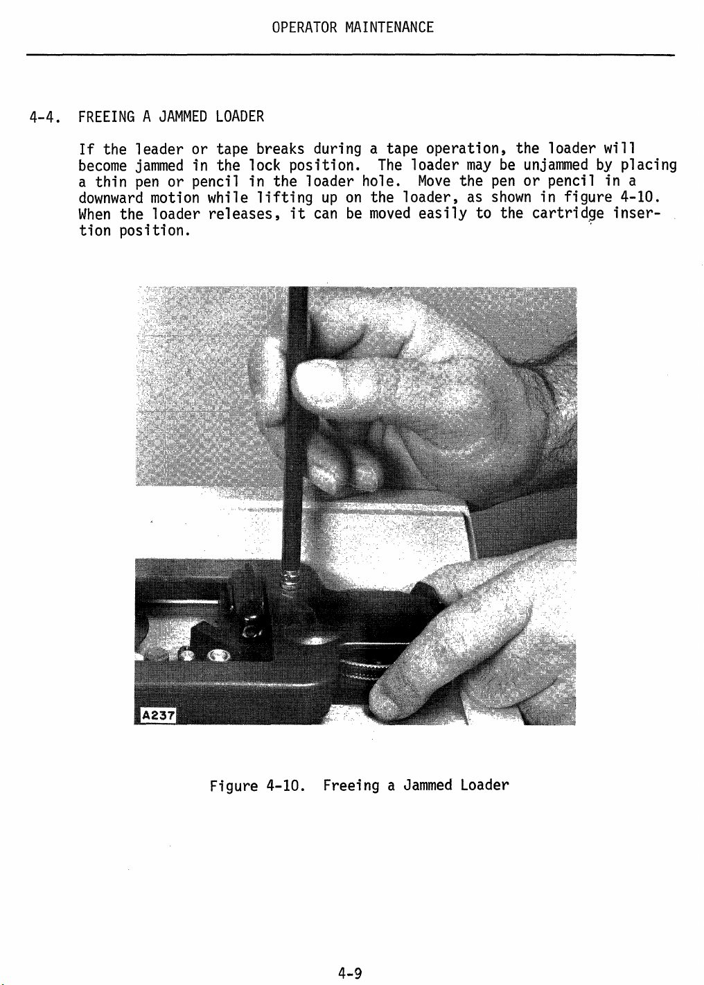
4-4.
FREEING A JAMMED
If
the leader or tape breaks during a tape operation, the loader will
become
a thin
downward
When
jammed
pen
or pencil in the loader hole.
motion
the loader
LOADER
in the lock position.
while
releases,
lifting
it
up
can
on
be
The
loader
Move
the loader,
moved
easily
may
be
unjammed
the
pen
or pencil in a
as
shown
in figure 4-10.
to the cartridge
tion position.
by
~
placing
inser-
Figure 4-10. Freeing a
4-9
Jammed
Loader
Page 29

OPERATOR
INSTRUCTIONS
FOR
THE
MODEL
Publication
We
produce
informative. That's our job.
So
welre asking
publications.
Add
any
comments
to include your
Does
If
this
not,
•
Please take a
manual
what
manuals
you
you
wish.
name
and
address.
meet
your needs?
additional information
1501
for you,
to help
few
minutes to
If
you
INTELLIGENT
No.
and
we
us
furnish
desire a reply to
Thank
would
TERMINAL
22-6504-01
want
you
you
answer
you.
be
of help to
to find
with the best possible
the following questions.
any
them
question,
you?
useful
be
sure
Yes
and
No
•
Can
you
find
what
you
Ire looking for,quickly
How
can
the organization
• Is the material easy to read
Are
Comments
•
Did
If
there
you
yes, please
enough
illustrations
------------------------------------------------------------
find
any
errors
cite
be
or ambiguities in the
page,
line,
improved:
and
to understand?
to support the text?
and/or figure
and
easily?
manual?
number
with your
Yes
Yes
Yes
comments.
No
No
No
Page 30

Staple
Fold
Staple
Back
Stamp
SINGER
BUSINESS
Publications
70
New
Dutch
Fairfield,
MACHINES
and
Lane
New
Jersey
Services
07006
Fold
Back
Page 31

,SINGER
BUSINESS
22-6504-01
MACHINES
 Loading...