

Page 1

SERVICE MANUAL
MS-H09AISW PT, MS-H12AISW PT
MULTI SYSTEM SERIES
SYMPHONY
Page 2

2
Page 3

1. Summary
Part
Ⅰ
: Technical Information
Indoor Unit
Remote Controller
MS-H09AISW PT
MS-H12AISW PT
YAA1FB1
3
Page 4

The above data is subject to change without notice; please refer to the nameplate of the unit.
Model
MS-H09AISW PT
Product Code
Rated Voltage V 220-240
Rated Frequency Hz 50
Phases 1
Min/Max Voltage V 198/264
Cooling Capacity KW 2.6
Heating Capacity KW 2.8
Air ow volume(max~min) m3/h 450/420/380/330/300/280/260
Dehumidifying Volume L/h 0.8
Fan Type Cross-ow
Fan Diameter-height mm Φ81X643
Cooling Fan Motor Speed(max~min) rpm 1350/1200/1100/1000/900/800/700
Heating Fan Motor Speed(max~min) rpm 1350/1250/1170/1090/1020/950/900
Fan Motor Power Output W 10
Fan motor Running Current A 0.13
Fan Motor Capacitor μF 1
Evaporator Material Aluminum Fin-copper Tube
Evaporator Pipe Diameter mm Φ7
Evaporator Number of Rows-Fin Pitch mm 2-1.5
Evaporator Length(L) X Height(H) X Width(W) mm 635X25.4X286
Fuse Current A 3.15
Sound Pressure Level (max~min) dB(A) 38/35/32/30/28/26/24
Sound Power Level (max~min) dB(A) 53/50/47/45/43/41/39
Dimension of Outline (WXHXD) mm 860X153X299
Dimension of Carton Box (LXWXH) mm 941X383X232
Dimension of Package (LXWXH) mm 944X386X247
Net Weight kg 9.5
Gross Weight kg 12.5
Liquid pipe mm Φ6
Gas Pipe(to indoor unit) mm Φ9.52
2. Specications
2.1 Specication Sheet
4
Page 5

Model
MS-H12AISW PT
Product Code
Rated Voltage V~ 220-240
Rated Frequency Hz 50
Phases 1
Min/Max Voltage V~ 198/264
Cooling Capacity KW 3.5
Heating Capacity KW 3.8
Air ow volume(max~min) m3/h 560/440/400/350/320/300/280
Dehumidifying Volume L/h 1.4
Fan Type Cross-ow
Fan Diameter-height mm Φ85X687
Cooling Fan Motor Speed(max~min) rpm 1350/1250/1150/1050/950/850/700
Heating Fan Motor Speed(max~min) rpm 1350/1270/1180/1100/1040/980/900
Fan Motor Power Output W 20
Fan motor Running Current A 0.2
Fan Motor Capacitor μF 1
Evaporator Material Aluminum Fin-copper Tube
Evaporator Pipe Diameter mm Φ7
Evaporator Number of Rows-Fin Pitch mm 2-1.4
Evaporator Length(L) X Height(H) X Width(W) mm 670X25.4X324
Fuse Current A 3.15
Sound Pressure Level (max~min) dB(A) 39/36/34/31/28/27/23
Sound Power Level (max~min) dB(A) 54/51/49/46/43/42/38
Dimension of Outline (WXHXD) mm 896X159X320
Dimension of Carton Box (LXWXH) mm 970X400X240
Dimension of Package (LXWXH) mm 973X403X255
Net Weight kg 11.5
Gross Weight kg 14.5
Liquid pipe mm Φ6
Gas Pipe(to indoor unit) mm Φ9.52
The above data is subject to change without notice; please refer to the nameplate of the unit.
5
Page 6

2.2 Noise Criteria Curve Tables for Both Models
High
Middle High
Middle
30
33
36
39
42
45
Super High
Middle Low
12K
18K
Low
Super Low
27
22
Noise/dB(A)
Indoor fan motor rotating speed
07K
09K
6
Page 7

W
QR S
D
H
Q
R
S
90 120
40
Φ55X2
90
67
Φ55X2
75
3. Outline Dimension Diagram
Unit: mm
07/09/12K
18K
Model W H D Q R S
09 860 299 153 118 542 200
12 896 320 159 64 542 290
7
Page 8

4. Refrigerant System Diagram
outdoor
indoor
D1
C
1
B1
A1
filter
A heat exchanger
gas -liquid separator
inverter compressor
discharge silencer
discharge temperature
sensor
SP
4-way valve
outdoor heat exchanger
fan
high pressure switch
B heat exchanger
C heat exchanger
D heat exchanger
filter
filter
filter
filter
Note: Not available for 14K/18K
model
C2
C3
D3
D2
B3
B2
A2
A3
A1:A-unit electronic expansion valve B1:B-unit electronic expansion valve
C1:C-unit electronic expansion valve D1:D-unit electronic expansion valve
A2:A-unit gas pipe temperature sensor B2:B-unit gas pipe temperature sensor
C2:C-unit gas pipe temperature sensor D2:D-unit gas pipe temperature sensor
A3:A-unit liquid pipe temperature sensor B3:B-unit liquid pipe temperature sensor
C3:C-unit liquid pipe temperature sensor D3:D-unit liquid pipe temperature sensor
Note: Not available for 14K/18K model
8
Page 9

5. Electrical Part
5.1 Wiring Diagram
● Indoor Unit
●Instruction
Symbol Symbol Color Symbol Symbol Color Symbol Name
WH White GN Green CAP Jumper cap
YE Yellow BN Brown COMP Compressor
RD Red BU Blue Grounding wire
YEGN Yellow/Green BK Black / /
VT Violet OG Orange / /
Note: Jumper cap is used to determine fan speed and the swing angle of horizontal lover for this model.
These wiring diagrams are subject to change without notice; please refer to the one supplied with the unit.
9
Page 10

1
2345 6789 10
11
12
13
14
15
16
1718
5.2 PCB Printed Diagram
1
风机电容
2
零线接口
3
风机接口
4
换气零线接口
5
冷等离子零线接口
6
换气火线接口
7
冷等离子火线接口
8
自动按键
9
风机反馈接口
10
上下扫风接口
11
左右扫风接口
12
显示接口
13
环境感温包接口
14
管路感温包接口
15
通讯接口
16
主芯片
17
蜂鸣器
18
火线接口
19
跳线帽
TOP VIEW
BOTTOM VIEW
19
10
Page 11

6. Function and Control
6.1 Remote Controller Introduction
Buttons on Remote Controller
Introduction for Icons on Display Screen
Introduction for Buttons on Remote Controller
T-ON T-OFF button
I FEEL button
/
ON/OFF button
MODE button
+/- button
QUIET button
SWING button
X-FAN button
TEMP button
TURBO button
SLEEP button
15
4
3
13
6
14
12
11
8
7
10
9
2
1
5
1
2
3
4
5
6
7
8
9
10
11
12
13
14
15
FAN button
button
ClOCK button
LIGHT button
/
Send signal
Turbo mode
8ć heating function
Set temperature
Set time
X-FAN function
TIMER ON /TIMER OFF
Child lock
Up & down swing
Left & right swing
Set fan speed
Light
Temp. display type
:Set temp.
:Outdoor ambient temp.
:Indoor ambient temp.
Sleep mode
Clock
Heat mode
Fan mode
Dry mode
Cool mode
Auto mode
Operation mode
I feel
Healthy mode
Scavenging functions
Quiet
ON/OFF button
1
Press this button to turn on the unit. Press this button again to turn off the unit.
ON/OFF button
+/- button
1
2
- button
Press this button to decrease set temperature. Holding it down above 2 seconds rapidly decreases set temperature. In AUTO
mode, set temperature is not adjustable.
Press this button to increase set temperature. Holding it down above 2 seconds rapidly increases set temperature. In AUTO
mode, set temperature is not adjustable.
+ button
11
Page 12

,
,
,
,
ON/OFF button
MODE button
+/- button
1
2
3
Each time you press this button , a mode is selected in a sequence that goes from AUTO,COOL, DRY, FAN, and HEAT * , as the
following:
After energization, AUTO mode is defaulted. In AUTO mode, the set temperature will not be displayed on the LCD, and the unit
will automatically select the suitable operation mode in accordance with the room temperature to make indoor room comfortable.(As
for cooling only unit,it won’t have any action when it receives the signal of heating operation.)
Press this button to set up &down swing angle, which circularly changes as below:
Press this button to turn on I FEEL function. The unit automatically adjust temperature according to the sensed temperature.
Press this button again to cancel I FEEL function.
Press this button, can select Sleep 1 ( ), Sleep 2 ( ),Sleep 3 ( ) and cancel the Sleep,circulate between these, after
electried, Sleep Cancel is defaulted.
Sleep 1 is Sleep mode 1, in Cool mode: after run for one hour in sleep mode, the main unit setting temperature will increase 1℃,
after 2 hours, the setting temperature will increase 2℃, but the maximal setting temperature is 30℃, then the unit will run at
this setting temperature all along; In Heat mode: after run for one hour in sleep mode, the setting temperature will decrease 1 ℃
after 2 hours the setting temperature will decrease 2℃, but the minimal setting temperature is 16℃, then the unit will run at this
setting temperature all along.
Sleep 2 is sleep mode 2, that is air conditioner will run according to the presetting a group of sleep temperature curve.
Sleep 3- the sleep curve setting under Sleep mode by DIY:
Press this button to achieve the on and off of healthy and scavenging functions in operation status. Press this button for the
rst time to start scavenging function; LCD displays " ". Press the button for the second time to start healthy and scavenging
functions simultaneously; LCD displays " " and " ". Press this button for the third time to quit healthy and scavenging
functions simultaneously. Press the button for the fourth time to start healthy function; LCD display " ". Press this button again
to repeat the operation above.Air function is applicable for some models.
This remote controller is universal. If any command , or is sent out, the unit will carry out the command as
indicates the guide louver swings as:
This button is used for setting Fan Speed in the sequence that goes from AUTO, to then back
to Auto.
*Note:Only for models with heating function.
ON/OFF button
MODE button
+/- button
1
2
3
4
FAN button
,
,
,
,
,
,
Auto
Medium speedLow-Medium speedLow speed
High speedMedium-High speed
ON/OFF button
MODE button
+/- button
SWING button
1
2
3
4
5
FAN button
I FEEL button
ON/OFF button
MODE button
+/- button
SWING button
1
2
3
4
5
6
FAN button
I FEEL button
/
ON/OFF button
MODE button
+/- button
SWING button
1
2
3
4
5
6
7
FAN button
button
I FEEL button
/
ON/OFF button
MODE button
+/- button
SWING button
SLEEP button
1
2
3
4
5
6
7
8
FAN button
button
(Only applicable for some models)
12
Page 13

(1) Under Sleep 3 mode, press "Turbo" button for a long time, remote control enters into user individuation sleep setting status, at this
time, the time of remote control will display "1hour ",the setting temperature "88" will display the corresponding temperature of last
setting sleep curve and blink (The rst entering will display according to the initial curve setting value of original factory);
(2) Adjust "+" and "-" button, could change the corresponding setting temperature, after adjusted, press "Trubo "button for conrmation;
(3) At this time, 1hour will be automatically increased at the timer postion on the remote control, (that are "2hours " or "3hours " or
"8hours "), the place of setting temperature "88" will display the corresponding temperature of last setting sleep curve and blink;
(4) Repeat the above step (2) ~ (3) operation, until 8hours temperature setting nished,sleep,curve setting nished, at this time, the
remote control will resume the original timer display;temperature display will resume to original setting temperature.
Sleep3- the sleep curve setting under Sleep mode by DIY could be inquired:
The user could accord to sleep curve setting method to inquire the presetting sleep curve,enter into user individuation sleep setting
status, but do not change the temperature, press "Turbo" button directly for confirmation.Note: In the above presetting or enquiry
procedure,if continuously within10s, there is no button pressed, the sleep curve setting within 10s, there is no button pressed, the sleep
curve setting status will be automatically quit and resume to display the original displaying. In the presetting or enquiry procedure, press
"ON/OFF" button, "Mode" button, "Timer"button or "Sleep" button, the sleep curve setting or enquiry status will quit similarly.
Press this button, the Quiet status is under the Auto Quiet mode (display " "signal )and Quiet mode (display " " singal) and Quiet
OFF (there is no signal of " "displayed),after powered on, the Quiet OFF is defaulted. Note: the Quiet function cannot be set up in
Fan and Dry mode;Under the Quiet mode (Display" " Under the Quiet mode) the fan speed is not available.
Press this button to activate / deactivate the Turbo function which enables the unit to reach the preset temperature in the shortest time.
In COOL mode, the unit will blow strong cooling air at super high fan speed. In HEAT mode, the unit will blow strong heating air at super
high fan speed.
Press T-ON button to initiate the auto-ON timer. To cancel the auto-timer program, simply press this button again.
After press of this button, disappears and "ON "blink s . 00:00 is displayed for ON time setting. Within 5 seconds, press + or - button
to adjust the time value. Every press of either button changes the time setting by 1 minute. Holding down either button rapidly changes
the time setting by 1 minute and then 10 minutes. Within 5 Seconds after setting, press TIMER ON button to conrm.
Press T-OFF button to initiate the auto-off timer. To cancel the auto-timer program, simply press the button again.TIMER OFF setting is
the same as TIMER ON.
Press CLOCK button,blinking. Within 5 seconds, pressing + or - button adjusts the present time. Holding down either button above
2 seconds increases or decreases the time by 1 minute every 0.5 second and then by 10 minutes every 0.5 second. During blinking
after setting, press CLOCK button again to conrm the setting, and then will be constantly displayed.
I FEEL button
/
ON/OFF button
MODE button
+/- button
SWING button
TEMP button
SLEEP button
1
2
3
4
5
6
7
8
9
FAN button
button
Press this button, you can see indoor set temperature, indoor ambient temperature on indoor unit’s display. The setting on remote
controller is selected circularly as below:
When selecting " " with remote controller or no display, temperature indicator on indoor unit displays set temperature; When
selecting " " with remote controller, temperature indicator on indoor unit displays indoor ambie nt temperature; 3s later or within 3s
it receives other remote control signal that will return to display the setting temperature.
Caution:
This model hasn't outdoor ambient temperature display function. While remote controller
can operate " " and indoor unit displays set temperature.
It’s defaulted to display set temperature when turning on the unit.
Only for the models with temperature indicator on indoor unit.
no display
I FEEL button
/
ON/OFF button
MODE button
+/- button
QUIET button
SWING button
TEMP button
SLEEP button
1
2
3
4
5
6
7
8
9
10
FAN button
button
Auto
Auto
Auto
Auto
I FEEL button
/
ON/OFF button
MODE button
+/- button
QUIET button
SWING button
TEMP button
SLEEP button
1
2
3
4
5
6
7
8
9
10
11
FAN button
button
ClOCK button
T-ON T-OFF button
I FEEL button
/
ON/OFF button
MODE button
+/- button
QUIET button
SWING button
TEMP button
SLEEP button
1
2
3
4
5
6
7
8
9
10
11
12
FAN button
button
ClOCK button
/
T-ON T-OFF button
I FEEL button
/
ON/OFF button
MODE button
+/- button
QUIET button
SWING button
TEMP button
TURBO button
SLEEP button
1
2
3
4
5
6
7
8
9
10
11
12
13
FAN button
button
ClOCK button
/
13
Page 14
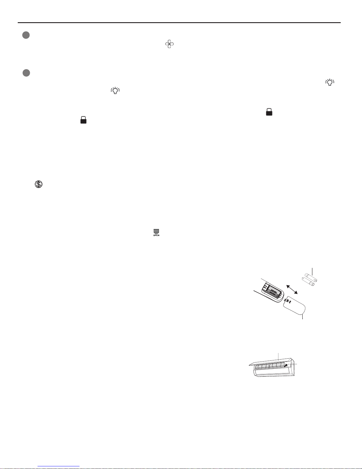
Note:
● During operation, point the remote control signal sender at the receiving window
on indoor unit.
● The distance between signal sender and receiving window should be no more than
8m, and there should be no obstacles between them.
● Signal may be interfered easily in the room where there is fluorescent lamp or
wireless telephone; remote controller should be close to indoor unit during operation.
● Replace new batteries of the same model when replacement is required.
● When you don’t use remote controller for a long time, please take out the batteries.
● If the display on remote controller is fuzzy or there’s no display, please replace
batteries.
1.Press the back side of remote controller marked with“ ”as shown in the g, and then push out the cover
of battery box along the arrow direction.
2. Replace two 7# (AAA 1.5V) dry batteries, and make sure the position of “+” polar and “-“ polar are correct.
3. Reinstall the cover of battery box.
Replacement of Batteries in Remote Controller
battery
Cover of battery box
remove
reinstall
T-ON T-OFF button
I FEEL button
/
ON/OFF button
MODE button
+/- button
QUIET button
SWING button
X-FAN button
TEMP button
TURBO button
SLEEP button
1
2
3
4
5
6
7
8
9
10
11
12
13
14
FAN button
button
ClOCK button
/
Combination of "+" and "-" buttons: About lock
Press "+" and "-" buttons simultaneously to lock or unlock the keypad. If the remote controller is locked, is displayed. In this case,
pressing any button, blinks three times.
Combination of "MODE" and "-" buttons:About switch between Fahrenheit and centigrade
At unit OFF, press "MODE" and "-" buttons simultaneously to switch between °C and °F.
Combination of "TEMP" and "CLOCK" buttons:About Energy-saving Function
Press "TEMP" and "CLOCK" simultaneously in COOL mode to start energy-saving function.Nixie tube on the remote controller displays
"SE". Repeat the operation to quit the function.
Combination of "TEMP" and "CLOCK" buttons:About 8°C Heating Function
Press "TEMP" and "CLOCK" simultaneously in HEAT mode to start 8°C Heating Function Nixie tube on the remote controller displays
" " and a selected temperature of "8°C".(46°F if Fahrenheit is adopted). Repeat the operation to quit the function.
About Back-lighting Function
The unit lights for 4s when energizing for the rst time, and 3s for later press.
Press LIGHT button to turn on the display's light and press this button again to turn off the display 's light. If the light is turned on , is
displayed. If the light is turned off, disappears.
T-ON T-OFF button
I FEEL button
/
ON/OFF button
MODE button
+/- button
QUIET button
SWING button
X-FAN button
TEMP button
TURBO button
SLEEP button
1
2
3
4
5
6
7
8
9
10
11
12
13
14
15
FAN button
button
ClOCK button
LIGHT button
/
Pressing X-FAN button in COOL or DRY mode, the icon is displayed and the indoor fan will continue operation for 2 minutes in
order to dry the indoor unit even though you have turned off the unit.
After energization, X-FAN OFF is defaulted. X-FAN is not available in AUTO, FAN or HEAT mode.
If remote controller is lost or damaged, please use auxiliary button to turn on or turn
off the air conditioner. The operation in details are as below: As shown in the g.
Open panel, press aux. button to turn on or turn off the air conditioner. When the air
conditioner is turned on, it will operate under auto mode.
Emergency Operation
Emergency operation
switch
Panel
14
Page 15

6.2 Brief Description of Modes and Functions
I. Basic Operation Mode
1. Cool; 2.Dry; 3.Heat; 4.Auto; 5.Fan
II. Basic Functions
1. Cooling Only
(1) Under cooling mode, fan and swing operate at setting status. Temperature setting range is 16~30℃.
(2) During malfunction of outdoor unit or stop operation, indoor unit keeps original operation status. Dual-8 nixie tube display error
code.
(3) Indoor fan stops operation during mode shock.
2. Drying mode
(1) Under drying mode, fan operates at low speed and swing operates at setting status. Temperature setting range is 16~30℃.
(2) During malfunction of outdoor unit or stop operation, indoor unit keeps original operation status. Dual-8 nixie tube display error
code.
(3) Protection status is same as that under cooling mode
3. Heating Mode
(1) Under heating mode, temperature setting range is 16~30℃.
(2) Operation condition and process for heating mode
After turning on the unit under heating mode, indoor unit operates according to cold air prevention condition;
During heating process, after room temperature is increased to set temperature,the complete unit stops operation. Indoor fan will
blow residual heat and delay 1min to stop operation.
During heating operation, after turning off the unit by remote controller, indoor fan will blow residual heat to delay 10s to stop operation.
(3) Protection Function.
When compressor stops operation due to malfunction (include malfunction of temperature sensor) during heating mode, indoor fan will
blow residual heat to delay 1min to stop operation.
(4) Defrosting and Oil Retrun
After receiving oil-return signal of heating from outdoor unit, heating indicator is ON 10s and OFF 0.5; When received defrosting signal
from outdoor unit, defrosting indicator is ON.
4. Auto mode
(1) Operation condition and process for auto mode
Under this mode, system will select operation mode (cooling, heating, fan) automatically according to the change of indoor ambient
temperature. There’s 30s auto delay protection for mode switchover.
◆
When Tindoor amb. ≥26℃, the system will operate under cooling mode; Ex-factory set temperature: Tpreset=25
℃
◆
Heat pump unit: When Tindoor amb. ≤22℃, the system operates under heating mode. Ex-factory set temperature: Tpreset=20
℃
◆
Cooling only unit: When Tindoor amb. ≤22℃, the system operates under fan mode. Ex-factory set temperature: Tpreset=25
℃
◆
When 22℃<Tindoor amb.<26℃: The unit will operate under fan mode when entering into auto mode after turning on the unit.
If switch to auto mode from cooling, heating or fan mode, the unit will keep original operation mode. If switch to auto mode from drying
mode, the unit will operate under fan mode.
(2) Display: operation icon, actual operation mode icon. Display set temperature, but it can’t be adjusted.
(3) Protection function is same as that under other modes. (refer to the section of system function protection)
5. Fan Mode
Under fan mode, indoor fan operates at set fan speed, while compressor and outdoor fan stops operation. 4-way valve is de-energized
(4-way valve is not available for cooling only unit). Temperature setting range is 16~30
℃.
III. Other Control
1. Buzzer
Upon energization or pressing button (emergency switch on air conditioner) or receiving signal from remote controller, the buzzer will
give out a beep.
2. Auto button
When pressing this button under OFF status, the complete unit will operate under auto mode and indoor unit will operate at auto fan
speed. Swing mode will operate when indoor fan is operating.
Press this button under ON status to turn off the unit.
3. Auto fan
(1) Auto fan speed under heating mode
When Tindoor amb.≤Tpreset+1℃, indoor fan will operate at high fan speed;
When Tpreset+1℃<Tindoor amb.<Tpreset+3℃, indoor fan operate at medium fan speed;
When Tindoor amb. ≥Tpreset+3℃, indoor fan operates at low fan speed;
15
Page 16

(2) Auto fan speed under cooling mode and fan mode
When Tamb.≥Tpreset+2℃, indoor fan operates at high fan speed;
When Tpreset<Tamb.<Tpreset+2℃, indoor fan operates at medium fan speed;
When Tamb.≤Tpreset, indoor fan operates at low fan speed;
(3) Auto fan speed under drying mode is defaulted at low fan speed.
Note: 1.Under auto fan speed, during switchover between high speed and medium speed, medium speed and low speed, and high
speed and low speed, there should at least 3min and 30s operation time.
2.Fan speed “high”, “medium”, and “low” is corresponding to “fan speed 5”, “fan speed 3” and “fan speed 1”.
4. Sleep
Sleep mode is only valid under cooling mode and heating mode;
Cooling mode: Basing on the set temperature of remote controller, after turning on the sleep function for a few hours, set temperature
will increase properly and automatically according to human body’s comfort.
Heating mode: Basing on the set temperature of remote controller, after turning on the sleep function for a few hours, set temperature
will decrease properly and automatically according to human body’s comfort.
5. Timer function
Controller is with general timer function and clock timer function simultaneously. When you selecting the remote controller with general
timer, you can only activate the general timer function of controller; when you selecting the remote controller with clock timer, you can
only activate the clock timer function of controller.
(1) General timer
Timer precision for general timer is 0.5hour, and 24hours circulating timer can’t be set.
◆
Timer ON can be set at unit OFF. If selected ON time is reached, the system will start to operate according to previous setting
status by remote controller. Time setting range is 0.5-24hr in 30-minute increments.
◆
Timer OFF can be set at unit ON. If selected OFF time is reached, the unit will stop operation. Time setting range is 0.5-24hr in
30-minute increments.
(2) Clock timer
Timer precision for clock timer is 1min, and 24hours circulating timer can be set.
◆
Timer ON:
If timer ON is set during operation of the unit, the unit will continue to operate. If timer ON is set at unit OFF, upon ON
time reaches the unit will start to operate according to previous setting status by remote controller.
◆
Timer OFF:
If timer OFF is set at unit OFF, the system will keep OFF status. If timer OFF is set at unit ON, upon OFF time reaches
the unit will stop operation.
◆
Timer change
Under timer status of system, you can set timer ON and timer OFF by pressing ON/OFF button on remote controller. You can also set
timer setting again and the system will operate according to the last setting status.
If timer ON and timer OFF are set at the same time during operation of the unit, the unit will keep operating at current status till OFF
time reaches. When ON time reaches, the unit will be turned on automatically. The unit will circulate like that every 24hours.
If timer ON and timer OFF are set at the same time at OFF status, the unit will OFF status till ON time reaches. When OFF time
reaches, the unit will be turned off automatically. The unit will circulate like that every 24hours.
6. Memory function
(1) Memory when power failure upon turning on the unit
◆
Memory content: ON status, mode, up&down swing, light, set temperature, set fan speed, general timer, Fahrenheit/ Centigrade,
◆
General timer can be memorized. Timer will be recalculated from the time of energization.
◆
Clock timer can’t be memorized.
(2) Memory when power failure upon turning off the unit
◆
Memory content: ON status, mode, up&down swing, light, set temperature, set fan speed, general timer, Fahrenheit/ Centigrade
◆
General timer can be memorized. Timer will be recalculated from the time of energization.
◆
Clock timer can’t be memorized.
7. Health function
During operation of the indoor fan, press health button on the remote controller to start health function (If there is not health button on
the remote controller, the unit defaults health function ON).
When the fan stops operation or press health button on remote controller again, health function will be turned off.
8. I FEEL function
When I FEEL command is received, the controller will operate according to the ambient temperature sent by the remote controller
(For defrosting and cold blow prevention, the unit operates according to the ambient temperature sensed by the air conditioner). The
remote controller will regularly send ambient temperature data to the controller. When the data has not been received for a long time,
the controller will operate according to the temperature sensed by the air conditioner. If I FEEL function hasn’t been started up, the
ambient temperature will be that sensed by the air conditioner.
16
Page 17

9. Reserve Fahrenheit display function
If the signal of remote controller is set at Fahrenheit temperature, set temperature display by dual-8 nixie tube is Fahrenheit
temperature. Set temperature range is 61~86°F.
If it needs to display indoor ambient temperature, indoor ambient temperature sent by remote controller will be display and then
temperature range is 0~60℃(32~99°F). Display will keep the set temperature no change if received outdoor ambient temperature
signal. After displaying ambient temperature for 3s, or receiving other valid remote control signal within 3s, the unit will turn back to
display set temperature.
10. Cold plasma function
After selecting cold plasma function by remote controller and indoor fan is operating, cold plasma function will be turned on.
After turning off cold plasma function by remote controller and indoor fan stops operation, cold plasma will be turned off.
11. Turbo function
After turbo function is started, indoor fan operate at super-high fan speed. Outdoor fan operates at high frequency under cooling or
heating mode.
12.About quiet, auto quiet function:
During operation of quiet function: Indoor fan operates under quiet mode.
During operation of auto quiet function:
1. Under cooling mode: When Tindoor amb. >28℃, indoor fan operates at fan speed 4 at rst. 10min later or when indoor ambient
temperature≤28℃, indoor fan will select fan speed 2 or quiet mode to operate according to the relationship between indoor ambient
temperature and set temperature.
2. Under heating mode: Indoor fan will select fan speed 2 or quiet mode to operate according to the relationship between indoor
ambient temperature and set temperature.
3. Under drying or fan mode: indoor fan operate at quiet mode.
4. Under auto mode, indoor fan will operate at the auto quiet mode under actual cooling, heating or fan mode.
13. Compulsory defrosting function
(1) Start up compulsory defrosting function
Under ON status, set heating mode with remote controller and adjust the temperature to 16℃. Press “+, -, +, -, +,-” button successively
within 5s and the complete unit will enter into compulsory defrosting status. Meanwhile, defrosting indicator is ON. (Note: If complete
unit has malfunction or stops operation due to protection, compulsory defrosting function can be started up after malfunction or
protection is resumed.
(2) Exit compulsory defrosting mode
After compulsory defrosting is started up, the complete unit will exit defrosting operation according to the actual defrosting result, and
the complete unit will resume normal heating operation.
14. Refrigerant recovery function (applicable for moving the unit or maintaining the unit)
(1) Start up refrigerant recovery function
Set cooling mode with remote controller within 5min after energization, adjust temperature at 16℃ and press light button on remote
controller for 3 times successively to any one indoor unit within 3s and then the complete unit will enter into refrigerant recovery status.
All indoor units display Fo. Maintenance person close all liquid valves. After 5min, withstand the thimble of all checking valves with tools
one by one. If there’s no refrigerant spraying out, close corresponding valve immediately, turn off the unit with remote controller and
then remove the connection pipe.
(2) Exit refrigerant recovery function
During refrigerant recovery process, if any one indoor unit receives any remote control signal or refrigerant recovery function has
operates for about 25min, refrigerant recovery function will be exited automatically. If the complete unit is at standby status before
refrigerant recovery, the complete unit will still at standby status after refrigerant recovery. If the complete unit is at ON status, the unit
will operate according to original operation mode.
After entering refrigerant recovery function: Indoor unit operates at cooling mode. Fan speed is super-high speed and set temperature
is 16°C. Horizontal will open at the minimum operation angle.
15.Dry and mildew-proof function
After setting dry function with remote controller under cooling or drying mode and then turn off the unit, indoor fan delay 2min to stop
operation to dry the fan. Horizontal louver will stop at horizontal position.
8℃ heating function (this function is realized by setting 8℃ heating signal with remote controller. Please refer to corresponding part of
remote controller in instruction manual)
8℃ heating function is only valid under heating mode. After setting is succeeded, indoor unit displays 8℃.
17
Page 18

Mode Indoor unit with
mode shock
Operation status after mode shock
Indoor unit A Indoor unit B Indoor unit A Indoor unit B
Cooling/drying heating Indoor unit B Cooling/drying
Indoor fan stops
operation
Heating Cooling, drying, fan Indoor unit B Heating
Indoor fan stops
operation
Fan Heating Indoor unit A
Indoor fan stops
operation
Heating
Turbo function can’t be set after setting 8℃ heating function. Fan speed is adjusted according to below condition:
When Tindoor amb.≤Tpreset+1℃, indoor fan operates at high speed;
When Tpreset+1℃<Tindoor amb.<Tpreset+3℃, indoor fan operate at medium speed;
When Tindoor amb.≥Tpreset+3℃, indoor fan operates at low speed;
There should be at least 3min and 30s operation time for the switchover among high speed, medium speed and low speed.
8℃ heating mode can’t be coexisted with sleeping mode (realized by remote controller). Eg
:
When you have set 8℃ heating mode, if you continue to set sleeping mode with remote controller, 8℃ heating mode will be canceled and
the unit operates at sleeping mode. Meanwhile, the set temperature value is the set temperature before entering into 8℃ heating mode.
On the contrary, when you have set sleeping mode, if you continue to set 8℃ heating mode with remote controller, sleeping mode will be
canceled and the unit will operates under 8℃ heating mode.
Other requirement and protection is same as that under heating mode.
If set 8℃ heating function again under 8℃ heating mode, it will exit 8℃ heating mode.
Comfortable and energy-saving function (this function is realized by setting energy-saving signal with remote controller. Please refer to
corresponding part of remote controller in instruction manual)
Comfortable and energy-saving function is only valid under cooling mode. After setting is succeeded, set temperature of indoor unit is 27℃
and indoor unit displays “SE”.
After setting is succeeded and compressor operates, fan speed is adjusted automatically according to below condition:
When Tamb.≥32℃, indoor fan operates at super-high speed;
When 32℃>Tamb.≥Tpreset+2℃, indoor fan operates at high speed;
When Tpreset<Tamb.<Tpreet+2℃, indoor fan operates at medium speed;
When Tamb.≤Tpreset, indoor fan operates at low speed.
After setting is succeeded and compressor operates, the unit operates at low speed.
There should be at least 3min and 30s operation time for the switchover among high speed, medium speed and low speed.
After entering into energy-saving mode and When Tamb. ≥28℃, horizontal louver operates at x-angle position 4. 10min later or Tamb.
<28℃ or after receiving the changing order for swing angle, horizontal louver will operate the angle set by remote controller.
Other requirement and protection is same as that under cooling mode.
If set energy-saving function again under energy-saving mode, it will exit energy-saving mode.
16. Mode shock
When there’s indoor unit under operation, if start up other indoor unit and the setting mode is inconsistent with that indoor unit, mode
shock will occur. The indoor with mode shock displays “E7” and indoor fan stops operation. Corresponding relationship for mode shock
and operation status after shock is as below:
Mode relationship table for mode shock:
18
Page 19

1. Select the installation location according to the requirement of this manual.(See the requirements in installation
part)
2. Handle unit transportation with care; the unit should not
be carried by only one person if it is more than 20kg.
3. When installing the indoor unit and outdoor unit, a sufcient xing bolt must be installed; make sure the installation
support is rm.
4. Ware safety belt if the height of working is above 2m.
5. Use equipped components or appointed components during installation.
6. Make sure no foreign objects are left in the unit after nishing installation.
Electrical Safety Precautions:
7. Notes for Installation and Maintenance
Safety Precautions:
Important!
Please read the safety precautions carefully before installation and maintenance.
The following contents are very important for installation
and maintenance.
Please follow the instructions below.
●The installation or maintenance must accord with the
instructions.
●Comply with all national electrical codes and local
electrical codes.
●Pay attention to the warnings and cautions in this
manual.
●All installation and maintenance shall be performed by
distributor or qualied person.
●All electric work must be performed by a licensed
technician according to local regulations and the
instructions given in this manual.
●Be caution during installation and maintenance. Prohibit
incorrect operation to prevent electric shock, casualty and
other accidents.
1. Cut off the power supply of air conditioner before
checking and maintenance.
2. The air condition must apply specialized circuit and
prohibit share the same circuit with other appliances.
3. The air conditioner should be installed in suitable
location and ensure the power plug is touchable.
4. Make sure each wiring terminal is connected firmly
during installation and maintenance.
5. Have the unit adequately grounded. The grounding
wire can’t be used for other purposes.
6. Must apply protective accessories such as protective
boards, cable-cross loop and wire clip.
7. The live wire, neutral wire and grounding wire of
power supply must be corresponding to the live wire,
neutral wire and grounding wire of the air conditioner.
8. The power cord and power connection wires can’t be
pressed by hard objects.
9. If power cord or connection wire is broken, it must be
replaced by a qualied person.
1. Avoid contact between refrigerant and re as it generates
poisonous gas; Prohibit prolong the connection pipe by
welding.
2. Apply specied refrigerant only. Never have it mixed with
any other refrigerant. Never have air remain in the refrigerant
line as it may lead to rupture or other hazards.
3. Make sure no refrigerant gas is leaking out when
installation is completed.
4. If there is refrigerant leakage, please take sufficient
measure to minimize the density of refrigerant.
5. Never touch the refrigerant piping or compressor without
wearing glove to avoid scald or frostbite.
Warnings
Refrigerant Safety Precautions:
Improper installation may lead to re hazard, explosion,
electric shock or injury.
Installation Safety Precautions:
Part
Ⅱ
: Installation and Maintenance
10. If the power cord or connection wire is not long enough,
please get the specialized power cord or connection wire
from the manufacture or distributor. Prohibit prolong the wire
by yourself.
11. For the air conditioner without plug, an air switch must
be installed in the circuit. The air switch should be all-pole
parting and the contact parting distance should be more than
3mm.
12. Make sure all wires and pipes are connected properly and
the valves are opened before energizing.
13. Check if there is electric leakage on the unit body. If yes,
please eliminate the electric leakage.
14. Replace the fuse with a new one of the same specication
if it is burnt down; don’t replace it with a cooper wire or
conducting wire.
15. If the unit is to be installed in a humid place, the circuit
breaker must be installed.
19
Page 20

Main Tools for Installation and Maintenance
1. Level meter, measuring tape
4. Electroprobe
7. Electronic leakage detector
10. Pipe pliers, pipe cutter
2. Screw driver
5. Universal meter
8. Vacuum pump
11. Pipe expander, pipe bender
3. Impact drill, drill head, electric drill
6. Torque wrench, open-end wrench, inner
hexagon spanner
9. Pressure meter
12. Soldering appliance, refrigerant container
20
Page 21

8. Installation
8.1 Installation Dimension Diagram
Space to the ceiling
Space to the wall
At least 15cm
At least 15cm
At least 15cm
At least 250cm
Space to the wall
Space to the obstruction
roolf eht ot ecapS
Drainage pipe
At least 300cm
21
Page 22

Preparation before installation
Prepare tools
Read the requirements
for electric connection
select installation
location
Select indoor unit
installation location
Install wall-mounting
frame, drill wall holes
Connect pipes of indoor
unit and drainage pipe
Connect wires of indoor unit
Connect wires of outdoor unit
Bind up pipes and
hang the indoor unit
Make the bound pipes pass
through the wall hole and then
connect outdoor unit
Neaten the pipes
Vacuum pumping and leakage detection
Check after installation and test operation
Finish installation
Note: this flow is only for reference; please find the more detailed installation steps in this section.
Select outdoor unit
installation location
Install the support of outdoor unit
(select it according to the actual situation)
Install drainage joint of outdoor unit
(only for cooling and heating unit)
Connect pipes of outdoor unit
Start installation
Fix outdoor unit
Installation procedures
22
Page 23

No. Name No. Name
1 Indoor unit 8 Sealing gum
2 Outdoor unit 9 Wrapping tape
3 Connection pipe 10
Support of outdoor
unit
4 Drainage pipe 11 Fixing screw
5
Wall-mounting
frame
12
Drainage plug(cooling
and heating unit)
6
Connecting
cable(power cord)
13
Owner’s manual,
remote controller
7 Wall pipe
1. Safety precaution
(1) Must follow the electric safety regulations when installing
the unit.
(2) According to the local safety regulations, use qualified
power supply circuit and air switch.
(3) Make sure the power supply matches with the requirement
of air conditioner. Unstable power supply or incorrect wiring
may result in electric shock,re hazard or malfunction. Please
install proper power supply cables before using the air
conditioner.
(4) Properly connect the live wire, neutral wire and grounding
wire of power socket.
(5) Be sure to cut off the power supply before proceeding any
work related to electricity and safety.
(6) Do not put through the power before nishing installation.
(7) For appliances with type Y attachment,the instructions
shall contain the substance of thefollowing.If the supply cord is
damaged,it must be replaced by the manufacturer,its service
agent or similarly qualied persons in order to avoid a hazard.
(8) The temperature of refrigerant circuit will be high, please
keep the interconnection cable away from the copper tube.
8.2 Installation Parts-checking
8.3 Selection of Installation Location
8.4 Electric Connection Requirement
8.5 Installation of Indoor Unit
1.Please contact the local agent for installation.
2.Don't use unqualied power cord.
1. Basic Requirement:
Installing the unit in the following places may cause
malfunction. If it is unavoidable, please consult the local dealer:
(1) The place with strong heat sources, vapors, ammable or
explosive gas, or volatile objects spread in the air.
(2) The place with high-frequency devices (such as welding
machine, medical equipment).
(3) The place near coast area.
(4) The place with oil or fumes in the air. in the air.
(5) The place with sulfureted gas.
(6) Other places with special circumstances.
2. Grounding requirement:
(1) The air conditioner is rst class electric appliance. It must
be properly grounding with specialized grounding device
by a professional. Please make sure it is always grounded
effectively, otherwise it may cause electric shock.
(2) The yellow-green wire in air conditioner is grounding wire,
which can't be used for other purposes.
(3) The grounding resistance should comply with national
electric safety regulations.
(4) The appliance must be positioned so that the plug is
accessible
(5) An all-pole disconnection switch having a contact separation
of at least 3mm in all poles should be connected in xed wiring.
(6) Including an air switch with suitable capacity, please note
the following table. Air switch should be included magnet
buckle and heating buckle function, it can protect the circuitshort and overload. (Caution: please do not use the fuse only
for protect the circuit)
1. Choosing Installation Iocation
Recommend the installation location to the client and then
conrm it with the client.
2. Install Wall-mounting Frame
(1) Hang the wall-mounting frame on the wall; adjust it in
horizontal position with the level meter and then point out the
screw xing holes on the wall.
(2) Drill the screw xing holes on the wall with impact drill (the
specification of drill head should be the same as the plastic
expansion particle) and then ll the plastic expansion particles
in the holes.
(3) Fix the wall-mounting frame on the wall with tapping screws
(ST4.2X25TA) and then check if the frame is rmly installed by
pulling the frame. If the plastic expansion particle is loose,
please drill another xing hole nearby.
2. Indoor Unit:
(1) There should be no obstruction near air inlet and air outlet.
(2) Select a location where the condensation water can be
dispersed easily and won't affect other people.
(3) Select a location which is convenient to connect the
outdoor unit and near the power socket.
(4) Select a location which is out of reach for children.
(5) The location should be able to withstand the weight of
indoor unit and won't increase noise and vibration.
(6) The appliance must be installed 2.5m above oor.
(7) Don't install the indoor unit right above the electric
appliance.
(8) The appliance shall not be installed in the laundry
Note:
23
Page 24

Outlet
pipe
Drain hose
Drain hose
Tape
Outlet pipe
Insulating pipe
Torque wrench
Open-end
wrench
Indoor pipe
Pipe
Union nut
Union nutPipe joint
Pipe
Hex nut diameter(mm) Tightening torque(N.m)
Φ6 15~20
Φ9.52 30~40
Φ12 45~55
Φ16 60~65
Φ19 70~75
Refer to the following table for wrench moment of force
:
Left
Rear left
Right
Rear right
Drain hose
Insulating pipe
(1) Pay attention to dust prevention and take relevant safety
measures when opening the hole.
(2) The plastic expansion particles are not provided and should
be bought locally.
(1) Add insulating pipe in the indoor drain hose in order to
prevent condensation.
(2) The plastic expansion particles are not provided.
(As show in Fig.10)
Fig.5 Fig.6
Fig.7
Fig.8
Fig.9
Fig.10
Fig.3
Fig.4
3. Install Wall-mounting Frame
(1) Choose the position of piping hole according to the direction
of outlet pipe. The position of piping hole should be a little
lower than the wall-mounted frame.(As show in Fig.1)
5. Connect the Pipe of Indoor Unit
(1) Aim the pipe joint at the corresponding bellmouth.(As show
in Fig.5)
(2) Pretightening the union nut with hand.
(3) Adjust the torque force by referring to the following sheet.
Place the open-end wrench on the pipe joint and place the
torque wrench on the union nut. Tighten the union nut with
torque wrench.(As show in Fig.6)
(4) Wrap the indoor pipe and joint of connection pipe with
insulating pipe, and then wrap it with tape.(As show in Fig.7)
6. Install Drain Hose
(1) Connect the drain hose to the outlet pipe of indoor unit.(As
show in Fig.8)
(2) Bind the joint with tape.(As show in Fig.9)
4. Outlet pipe
(1) The pipe can be led out in the direction of right, rear right,
left or rear left.(As show in Fig.3)
(2) When selecting leading out the pipe from left or right, please
cut off the corresponding hole on the bottom case.(As show in
Fig.4)
(2) Open a piping hole with the diameter of Φ55 on the selected
outlet pipe position.In order to drain smoothly, slant the piping
hole on the wall slightly downward to the outdoor side with the
gradient of 5-10°.(As show in Fig.2)
Note:
Note:
5-10
°
Φ55
Indoor
Outdoor
Fig.2
Wall
Wall
Mark on the middle of it
Gradienter
Left
Right
(Rear piping hole)
(Rear piping hole)
Space
to the
wall
above
Space
to the
wall
above
1 5 0mm
1 5 0mm
Φ55mm
Φ55mm
Cut off
the hole
Left Right
24
Page 25

(4) Put wiring cover back and then tighten the screw.
(5) Close the panel.
Indoor unit
Gas
pipe
Indoor and
outdoor power cord
Liquid
pipe
Drain hose
Band
Drain hose
Band
Connection pipe
Indoor power cord
Power connection
wire
Cable-cross
hole
(1) All wires of indoor unit and outdoor unit should be
connected by a professional.
(2) If the length of power connection wire is insufcient, please
contact the supplier for a new one. Avoid extending the wire by
yourself.
(3) For the air conditioner with plug, the plug should be
reachable after nishing installation.
(4) For the air conditioner without plug, an air switch must be
installed in the line. The air switch should be all-pole parting
and the contact parting distance should be more than 3mm.
(1) The power cord and control wire can't be crossed or
winding.
(2) The drain hose should be bound at the bottom.
Do not bend the drain hose too excessively in order to prevent
blocking.
7. Connect Wire of Indoor Unit
(1) Open the panel, remove the screw on the wiring cover and
then take down the cover.(As show in Fig.11)
8. Bind up Pipe
(1) Bind up the connection pipe, power cord
and drain hose with the band.(As show in Fig.14)
(2) Reserve a certain length of drain hose and power cord
for installation when binding them. When binding to a certain
degree, separate the indoor power and then separate the drain
hose.(As show in Fig.15)
(3) Bind them evenly.
(4) The liquid pipe and gas pipe should be bound separately at
the end.
9. Hang the Indoor Unit
(1) Put the bound pipes in the wall pipe and then make them
pass through the wall hole.
(2) Hang the indoor unit on the wall-mounting frame.
(3) Stuff the gap between pipes and wall hole with sealing gum.
(4) Fix the wall pipe.
(As show in Fig.16)
(5) Check if the indoor unit is installed rmly and closed to the
wall.(As show in Fig.17)
(2) Make the power connection wire go through the cable-cross
hole at the back of indoor unit and then pull it out from the front
side.(As show in Fig.12)
(3) Remove the wire clip; connect the power connection wire
to the wiring terminal according to the color; tighten the screw
and then x the power connection wire with wire clip.(As show
in Fig.13)
Note:
Note:
Note:
Indoor
Outdoor
Wall pipe
Sealing gum
Fig.11
Fig.12
Fig.13
Fig.14
Fig.15
Fig.16
Fig.17
Wiring cover
Screw
Panel
Connect to outdoor unit
brown
yellow-
green
N(1)
black
blue
23
Upper hook
Lower hook of
wall-mounting frame
25
Page 26

NO. Items to be checked Possible malfunction
1
Has the unit been
installed rmly?
The unit may drop, shake or
emit noise.
2
Have you done the
refrigerant leakage test?
It may cause insufcient cooling
(heating) capacity.
3
Is heat insulation of
pipeline sufcient?
It may cause condensation and
water dripping.
4 Is water drained well?
It may cause condensation and
water dripping.
5
Is the voltage of power
supply according to the
voltage marked on the
nameplate?
It may cause malfunction or
damage the parts.
6
Is electric wiring and
pipeline installed
correctly?
It may cause malfunction or
damage the parts.
7
Is the unit grounded
securely?
It may cause electric leakage.
8
Does the power cord
follow the specication?
It may cause malfunction or
damage the parts.
9
Is there any obstruction
in air inlet and air outlet?
It may cause insufcient cooling
(heating).
10
The dust and
sundries caused
during installation are
removed?
It may cause malfunction or
damaging the parts.
11
The gas valve and liquid
valve of connection pipe
are open completely?
It may cause insufcient cooling
(heating) capacity.
1. Check after Installation
Check according to the following requirement after finishing
installation.
2. Test operation
(1) Preparation of test operation
● The client approves the air conditioner installation.
● Specify the important notes for air conditioner to the client.
(2) Method of test operation
● Put through the power, press ON/OFF button on the remote
controller to start operation.
● Press MODE button to select AUTO, COOL, DRY, FAN and
HEAT to check whether the operation is normal or not.
● If the ambient temperature is lower than 16℃, the air
conditioner can’t start cooling.
8.6 Check after Installation and Test
Operation
26
Page 27

9. Maintenance
9.1 Error Code
1. Malfunction display requirement
When there are several malfunctions, they will be displayed circularly.
2. Malfunction display method
(1) Hardware malfunction: immediate display; refer to “error code list”;
(2) Operation state: immediate display; refer to “error code list”;
(3) Other malfunctions: it is displayed after the compressor stops for 200s; refer to “error code list”.
Note: when the compressor is restarted, the malfunction display delay time (200s) is cleared.
3. Display control viaremote controller
Enter display control: press light button successively for 6 times within 3s to display the corresponding malfunction code;
Exit display control: pressing light button successively for 6 times within 3s or after display is shown for 5min, the display will
terminate.
Malfunction Name Malfunction types
Dual-8
Nixie Tube
Indicator Display
Operation
indicator
Cooling
indicator
Heating
indicator
Fault in input power zero Hardware malfunction U8
Jumper cap malfunction protection Hardware malfunction C5
No feedback of indoor fan motor Hardware malfunction H6
Indoor ambient sensor open or short circuit Hardware malfunction F1
Indoor tube sensor open or short circuit Hardware malfunction F2
Inlet tube sensor malfunction Hardware malfunction b5
Outlet tube sensor malfunction Hardware malfunction b7
IPM sensor circuit malfunction Hardware malfunction P7
Outdoor ambient sensor open or short circuit Hardware malfunction F3
Inlet pipe temperature sensor of outdoor
condenser is open-circuit/short circuit(commercial
air con)
Hardware malfunction A5
Outdoor tube sensor open or short circuit Hardware malfunction F4
outlet pipe temperature sensor of outdoor
condenser is open-circuit/short circuit(commercial
air con)
Hardware malfunction A7
Exhaust sensor open or short circuit Hardware malfunction F5
Communication failure between indoor unit and
outdoor unit
Hardware malfunction E6
Compressor phase current detection circuit
malfunction
Hardware malfunction U1
Compressor demagnetization protection It can be displayed
through remote
controller within 200s
and displayed directly
after 200s
HE
PN voltage drop protection U3
IPM high temperature protection P8
Refrigerant-lacking or blockage protection F0
Capacitor charge malfunction Hardware malfunction PU
Refrigerant system high pressure protection Hardware malfunction E1
system low-pressure protection (reserved) Hardware malfunction E3
Compressor over load protection
It can be displayed
through remote
controller within 200s
and displayed directly
after 200s
H3
Fault in matching Hardware malfunction LP
Loading EEPROM malfunction Hardware malfunction EE
AC current detect circuit malfunction Hardware malfunction U5
Error Code List
27
Page 28

Outdoor DC fan motor 1 malfunction Hardware malfunction L3
Outdoor DC fan motor 2 malfunction Hardware malfunction LA
Drive board ambient temperature sensor
malfunction (commercial)
Hardware malfunction
PF
AC contactor protection (commercial) Hardware malfunction P9
Temperature drift protection (commercial) Hardware malfunction PE
Sensor connection protection (commercial) Hardware malfunction Pd
Drive board communication malfunction
(commercial)
Hardware malfunction
P6
Wrong connection of communication wire or
expansion valve malfunction (free match)
Hardware malfunction
dn
Wrong connection of communication wire or
expansion valve malfunction detection status
(free match)
Hardware malfunction
dd
Outdoor unit malfunction flag bit Hardware malfunction oE
Mode conflict Operation status E7
Recovery refrigerant mode Operation status Fo
Defrosting or oil return in heating Operation status
OFF for 0.5s
and ON for 10s
Startup failure
It can be displayed
through remote
controller within 200s
and displayed directly
after 200s
Lc
Compressor exhaust high temperature
protection
E4
Anti-high temperature protection E8
AC over-current protection E5
Over compressor phase current protection P5
Compressor loss step protection H7
Compressor loss of phase protection Ld
IPM protection H5
Low PN voltage protection PL
Over voltage protection for PN PH
PFC protection HC
4-way valve reversal abnormal U7
Compressor open phase protection U2
Over high power protection (not applicable
for residential outdoor unit)
L9
Compressor stalling (commercial) LE
Drive modular reset (commercial) P0
Overspeed (commercial) LF
28
Page 29

9.2 Procedure of Troubleshooting
1. Malfunction of Temperature Sensor F1, F2
Start
Insert the temperature
sensor tightly
yes
Ma lfunction is
eliminated.
Make the parts upright
yes
Malfunction is
eliminated.
Replace the controller with
one of the same model
End
no
no
no
no
yes
yes
Malfunction is
removed.
no
yes
yes
no
Is the wiring
terminal between temperature
sensor and the controller loosened or
poo rly contacted?
Is there short circuit due to tri-pover
of the pa rts?
Is the temperature
sensor normal according to the
Resistance Table?
Replace it with a
temperature sensor
of the same model
29
Page 30

2.
Malfunction of Blocked Protection of IDU Fan Motor H6
END
No
Yes
No
Yes
No
Yes
Yes
Yes
No
No
No
Yes
start
Yes
No
It's the malfunction
of motor. Replace
the motor.
It's the malfunction of
main board.
Replace
the main board with
the same model
It's the malfunction of
main board.
Replace
the main board with
the same model
It's the malfunction of
main board.
Replace
the main board with
the same model
Pull the blade by
hand under
de-energization
status
Whether the
blade can operate
smoothly
Adjust the motor and
blade assembly to let
the motor can operate
smoothly
Check whether the
wiring terminal between
indoor fan and main
board is loose
Reinsert the wiring
terminal of indoor fan
Energize and restart up the
unit, test whether the voltage beween black
terminal and white terminal of motor
interface is 280~310VDC
Test whether the voltage bewween
black terminal and white terminal of motor
interface
is 15VDC
Test whether there's voltage signal
beween black terminal and yellow
terminal of motor interface
Check whether
the malfunction is elliminated
after energization
Check whether
the malfunction is elliminated
after energization
30
Page 31

Appearance of
the jumper cap
Troubleshooting for C5
malfunction
Is there jumper cap on the
mainboard
?
Is
the jumper cap inserted
correctly and
tightly
?
Replace the jumper cap
withthe same model
End
yes
yes
Assemble the jumper
cap with the same
model
no
Is malf unction
elim inated
no
yes
Insert the
jumper cap
tightly
Is malfunction
eliminated
no
no
yes
Is malfunction
eliminated
no
yes
Replace the mainboard
with the same model.
3.
Malfunction of Protection of Jumper Cap C5
31
Page 32

Troubleshooting
for U8 malfunction
Re-energize1
minute after
de-erergization
U8 is still
displayed
The unit returns to normal.
Conclusion:U8 is displayed due
to instant energization afte deenergization while the capacitor
discharges slowly.
The zero-cross detection
circuit of the mainboard is
defined abnormal.Replace
the mainboard with the same
model
End
No
Yes
4.
Malfunction of Zero-crossing Inspection Circuit Malfunction of the IDU Fan Motor U8
32
Page 33

5. E6 Malfunction
Communication malfunction o
f
some indoor units
Does the
broken-down indoor
unit resume normal?
De-energize the unit and check
if the connecting wire of indoor
and outdoor unit and wiring of
electric box are correct.
Is wire connected
correctly˛
Connect wires
according to the
wiring diagram
De-energize the unit. Change the communication cable
of indoor units. Energize the unit and wait for 3 min
Yes
No
Replace mainboard
of outdoor unit
Replace the broken-down
mainboard of the indoor unit
No
Yes
End
Is malfunction
removed˛
Yes
No
33
Page 34

Communication malfunction o
f
all indoor units
De-energize the unit and check if the
connecting wire of indoor and outdoor unit
and wiring of electric box are correct.
Is wire connected
correctly˛
Connect wires
according to the
wiring diagram
De-energize the unit. Check if the connecting wire
between outdoor mainbaord and filter plate is correct.
Yes
No
Check if there is power input between
neutral wire and live wire of outdoor unit.
No
Yes
End
Is malfunction
removed˛
Yes
No
Does communication
resume normal˛
Is there power
in
p
ut?
Replace filter plate of
outdoor unit
Replace mainboard of outdoor unit
Is wire connected
correctl
y
˛
Replace mainboard
of indoor unit
Is connecting wire
dama
g
ed˛
Replace the
connecting wire
Connect wires
according to the
wiring diagram
Yes
No
Yes
No
No
Yes
Yes
No
No
Yes
Yes
No
Is malfunction
removed˛
Is malfunction
removed˛
Is malfunction
removed˛
34
Page 35

11. Removal Procedure
Caution: discharge the refrigerant
completely before removal.
clasps
Procedure
Steps
1. Before disassembly
2. Remove lter
front panel
Loosen clasps on filter and push the filter
inwards. Then lift it up to remove it.
Loosen clasps on both sides of front panel and
open front panel.
1
2
Take A1 panel for example
35
Page 36

Procedure
Steps
3. Remove front panel
4. Remove horizontal louver
Remove axle sleeve of horizontal louver
and bend the horizontal louver. Then draw it
outwards to remove it.
Remove screws fixing display on front panel.
Slide rotating shaft of front panel along the
groove to remove the front panel.
display
horizontal louver
rotating shaft
front panel
screws
clasps
5. Remove front case
Open screw caps and remove 6 screws fixing
front case and 1 screw on electric box cover 2.
screws
screw
1
36
Page 37

Procedure
Steps
6. Remove electric box subassembly
Loosen clasps on the joint of electric box cover
1 and electric box. Then remove electric box
cover 1.
Remove electric box cover 2
Loosen clasps on the rear of front case. Lift the
front case up to remove it.
1
2 Unplug splicing ear of motor and step motor
inside electric box.
front case
electric box cover 2
electric box cover 1
2
3
37
Page 38

Procedure
Steps
7. Remove evaporator
Remove screws on connecting pipe clamp and
then remove the connecting pipe clamp.
Remove screw xing electric box.
Remove electric box subassembly.
Remove screws on the joint of evaporator and
rear case. Slightly adjust pipe of evaporator and
then remove evaporator.
3
4
1
2
evaporator
electric box subassembly
screw
screw
connecting pipe clamp
38
Page 39

Procedure
Steps
8. Remove cross ow fan blade and motor
Unplug holder of bearing ring.
Remove motor clamp and step motor.
Remove screws on the joint of cross flow fan
blade and motor.
Remove motor.
Remove screws fixing motor clamp and step
motor.
motor
holder of bearing ring
screw
screws
motor clamp
step motor
1
2
3
4
5
39
Page 40

Procedure
Steps
9. Remove vertical louver
Loosen clasps between vertical louver and rear
case. Then remove vertical louver.
vertical louver
40
Page 41

Appendix:
1.Standard length of connection pipe
● 5m, 7.5m, 8m.
2.Min. length of connection pipe is 3m.
3.Max. length of connection pipe and max. high difference.
4.The additional refrigerant oil and refrigerant charging required after
prolonging connection pipe
● After the length of connection pipe is prolonged for 10m at the basis
of standard length, you should add 5ml of refrigerant oil for each
additional 5m of connection pipe.
● The calculation method of additional refrigerant charging amount (on
the basis of liquid pipe):
Appendix 1: Reference Sheet of Celsius and Fahrenheit
Appendix 2: Conguration of Connection Pipe
Cooling capacity
Max length of
connection pipe
Max height
difference
5000 Btu/h(1465 W) 15 m 5 m
7000 Btu/h(2051 W) 15 m 5 m
9000 Btu/h(2637 W) 15 m 10 m
12000 Btu/h(3516 W) 20 m 10 m
18000 Btu/h(5274 W) 25 m 10 m
24000 Btu/h(7032 W) 25 m 10 m
28000 Btu/h(8204 W) 30 m 10 m
36000 Btu/h(10548 W) 30 m 20 m
42000 Btu/h(12306 W) 30 m 20 m
48000 Btu/h(14064 W) 30 m 20 m
Set temperature
Conversion formula for Fahrenheit degree and Celsius degree: Tf=Tcx1.8+32
Ambient temperature
Fahrenheit
display
temperature
(℉)
Fahrenheit
(℉)
Celsius
(℃)
Fahrenheit
display
temperature
(℉)
Fahrenheit
(℉)
Celsius
(℃)
Fahrenheit
display
temperature
(℉)
Fahrenheit
(℉)
Celsius
(℃)
32/33 32 0 55/56 55.4 13 79/80 78.8 26
34/35 33.8 1 57/58 57.2 14 81 80.6 27
36 35.6 2 59/60 59 15 82/83 82.4 28
37/38 37.4 3 61/62 60.8 16 84/85 84.2 29
39/40 39.2 4 63 62.6 17 86/87 86 30
41/42 41 5 64/65 64.4 18 88/89 87.8 31
43/44 42.8 6 66/67 66.2 19 90 89.6 32
45 44.6 7 68/69 68 20 91/92 91.4 33
46/47 46.4 8 70/71 69.8 21 93/94 93.2 34
48/49 48.2 9 72 71.6 22 95/96 95 35
50/51 50 10 73/74 73.4 23 97/98 96.8 36
52/53 51.8 11 75/76 75.2 24 99 98.6 37
54 53.6 12 77/78 77 25
Fahrenheit
display
temperature
(℉)
Fahrenheit
(℉)
Celsius
(℃)
Fahrenheit
display
temperature
(℉)
Fahrenheit
(℉)
Celsius
(℃)
Fahrenheit
display
temperature
(℉)
Fahrenheit
(℉)
Celsius
(℃)
61 60.8 16 69/70 69.8 21 78/79 78.8 26
62/63 62.6 17 71/72 71.6 22 80/81 80.6 27
64/65 64.4 18 73/74 73.4 23 82/83 82.4 28
66/67 66.2 19 75/76 75.2 24 84/85 84.2 29
68 68 20 77 77 25 86 86 30
Additional refrigerant charging amount for R22, R407C, R410A and R134a
Diameter of connection pipe Outdoor unit throttle
Liquid pipe(mm) Gas pipe(mm) Cooling only(g/m) Cooling and heating(g/m)
Ф6 Ф9.5 or Ф12 15 20
Ф6 or Ф9.5 Ф16 or Ф19 15 20
Ф12 Ф19 or Ф22.2 30 120
Ф16 Ф25.4 or Ф31.8 60 120
Ф19 / 250 250
Ф22.2 / 350 350
● When the length of connection pipe is above 5m, add refrigerant according to the prolonged length of liquid pipe. The additional
refrigerant charging amount per meter is different according to the diameter of liquid pipe. See the following sheet.
● Additional refrigerant charging amount = prolonged length of liquid pipe X additional refrigerant charging amount per meter
41
Page 42

F:Inspection
● Check the quality of expanding port. If there is any blemish, expand the
port again according to the steps above.
The length is equal
Improper expanding
leaning
damaged
surface
crack uneven
thickness
Smooth surface
Downwards
Pipe
Shaper
Union pipe
Pipe
Expander
Hard
mold
Pipe
Pipe
Pipe cutter
Leaning Uneven Burr
Improper pipe expanding is the main cause of refrigerant leakage.Please
expand the pipe according to the following steps:
A:Cut the pip
● Conrm the pipe length according to the distance of indoor unit and outdoor unit.
● Cut the required pipe with pipe cutter.
B:Remove the burrs
● Remove the burrs with shaper and prevent the burrs from getting into the pipe.
C:Put on suitable insulating pipe
D:Put on the union nut
● Remove the union nut on the indoor connection pipe and outdoor valve; install
the union nut on the pipe.
E:Expand the port
● Expand the port with expander.
● "A" is different according to the diameter, please refer to the sheet below:
Outer diameter(mm)
A(mm)
Max Min
Ф6 - 6.35 (1/4") 1.3 0.7
Ф9.52 (3/8”) 1.6 1.0
Ф12 - 12.70 (1/2”) 1.8 1.0
Ф16 - 15.88 (5/8”) 2.4 2.2
Appendix 3: Pipe Expanding Method
Note:
Note:
42
Page 43

Appendix 4: List of Resistance for Ambient Temperature Sensor
Resistance Table of Ambient Temperature Sensor for Indoor and Outdoor Units(15K)
Temp(oC) Resistance(kΩ) Temp(oC) Resistance(kΩ) Temp(oC) Resistance(kΩ) Temp(oC) Resistance(kΩ)
-19 138.1 20 18.75 59 3.848 98 1.071
-18 128.6 21 17.93 60 3.711 99 1.039
-17 121.6 22 17.14 61 3.579 100 1.009
-16 115 23 16.39 62 3.454 101 0.98
-15 108.7 24 15.68 63 3.333 102 0.952
-14 102.9 25 15 64 3.217 103 0.925
-13 97.4 26 14.36 65 3.105 104 0.898
-12 92.22 27 13.74 66 2.998 105 0.873
-11 87.35 28 13.16 67 2.896 106 0.848
-10 82.75 29 12.6 68 2.797 107 0.825
-9 78.43 30 12.07 69 2.702 108 0.802
-8 74.35 31 11.57 70 2.611 109 0.779
-7 70.5 32 11.09 71 2.523 11 0 0.758
-6 66.88 33 10.63 72 2.439 111 0.737
-5 63.46 34 10.2 73 2.358 112 0.717
-4 60.23 35 9.779 74 2.28 113 0.697
-3 57.18 36 9.382 75 2.206 114 0.678
-2 54.31 37 9.003 76 2.133 115 0.66
-1 51.59 38 8.642 77 2.064 116 0.642
0 49.02 39 8.297 78 1.997 11 7 0.625
1 46.6 40 7.967 79 1.933 11 8 0.608
2 44.31 41 7.653 80 1.871 11 9 0.592
3 42.14 42 7.352 81 1.811 120 0.577
4 40.09 43 7.065 82 1.754 121 0.561
5 38.15 44 6.791 83 1.699 122 0.547
6 36.32 45 6.529 84 1.645 123 0.532
7 34.58 46 6.278 85 1.594 124 0.519
8 32.94 47 6.038 86 1.544 125 0.505
9 31.38 48 5.809 87 1.497 126 0.492
10 29.9 49 5.589 88 1.451 127 0.48
11 28.51 50 5.379 89 1.408 128 0.467
12 27.18 51 5.197 90 1.363 129 0.456
13 25.92 52 4.986 91 1.322 130 0.444
14 24.73 53 4.802 92 1.282 131 0.433
15 23.6 54 4.625 93 1.244 132 0.422
16 22.53 55 4.456 94 1.207 133 0.412
17 21.51 56 4.294 95 1.171 134 0.401
18 20.54 57 4.139 96 1.136 135 0.391
19 19.63 58 3.99 97 1.103 136 0.382
43
Page 44

Resistance Table of Ambient Temperature Sensor for Indoor and Outdoor Units(20K)
Temp(oC) Resistance(kΩ) Temp(oC) Resistance(kΩ) Temp(oC) Resistance(kΩ) Temp(oC) Resistance(kΩ)
-19 181.4 20 25.01 59 5.13 98 1.427
-18 171.4 21 23.9 60 4.948 99 1.386
-17 162.1 22 22.85 61 4.773 100 1.346
-16 153.3 23 21.85 62 4.605 101 1.307
-15 145 24 20.9 63 4.443 102 1.269
-14 137.2 25 20 64 4.289 103 1.233
-13 129.9 26 19.14 65 4.14 104 1.198
-12 123 27 18.13 66 3.998 105 1.164
-11 116.5 28 17.55 67 3.861 106 1.131
-10 110.3 29 16.8 68 3.729 107 1.099
-9 104.6 30 16.1 69 3.603 108 1.069
-8 99.13 31 15.43 70 3.481 109 1.039
-7 94 32 14.79 71 3.364 110 1.01
-6 89.17 33 14.18 72 3.252 111 0.983
-5 84.61 34 13.59 73 3.144 112 0.956
-4 80.31 35 13.04 74 3.04 113 0.93
-3 76.24 36 12.51 75 2.94 114 0.904
-2 72.41 37 12 76 2.844 115 0.88
-1 68.79 38 11.52 77 2.752 116 0.856
0 65.37 39 11.06 78 2.663 117 0.833
1 62.13 40 10.62 79 2.577 118 0.811
2 59.08 41 10.2 80 2.495 119 0.77
3 56.19 42 9.803 81 2.415 120 0.769
4 53.46 43 9.42 82 2.339 121 0.746
5 50.87 44 9.054 83 2.265 122 0.729
6 48.42 45 8.705 84 2.194 123 0.71
7 46.11 46 8.37 85 2.125 124 0.692
8 43.92 47 8.051 86 2.059 125 0.674
9 41.84 48 7.745 87 1.996 126 0.658
10 39.87 49 7.453 88 1.934 127 0.64
11 38.01 50 7.173 89 1.875 128 0.623
12 36.24 51 6.905 90 1.818 129 0.607
13 34.57 52 6.648 91 1.736 130 0.592
14 32.98 53 6.403 92 1.71 131 0.577
15 31.47 54 6.167 93 1.658 132 0.563
16 30.04 55 5.942 94 1.609 133 0.549
17 28.68 56 5.726 95 1.561 134 0.535
18 27.39 57 5.519 96 1.515 135 0.521
19 26.17 58 5.32 97 1.47 136 0.509
44
Page 45

Resistance Table of Ambient Temperature Sensor for Indoor and Outdoor Units(50K)
Temp(oC) Resistance(kΩ) Temp(oC) Resistance(kΩ) Temp(oC) Resistance(kΩ) Temp(oC) Resistance(kΩ)
-29 853.5 10 98 49 18.34 88 4.75
-28 799.8 11 93.42 50 17.65 89 4.61
-27 750 12 89.07 51 16.99 90 4.47
-26 703.8 13 84.95 52 16.36 91 4.33
-25 660.8 14 81.05 53 15.75 92 4.20
-24 620.8 15 77.35 54 15.17 93 4.08
-23 580.6 16 73.83 55 14.62 94 3.96
-22 548.9 17 70.5 56 14.09 95 3.84
-21 516.6 18 67.34 57 13.58 96 3.73
-20 486.5 19 64.33 58 13.09 97 3.62
-19 458.3 20 61.48 59 12.62 98 3.51
-18 432 21 58.77 60 12.17 99 3.41
-17 407.4 22 56.19 61 11.74 100 3.32
-16 384.5 23 53.74 62 11.32 101 3.22
-15 362.9 24 51.41 63 10.93 102 3.13
-14 342.8 25 49.19 64 10.54 103 3.04
-13 323.9 26 47.08 65 10.18 104 2.96
-12 306.2 27 45.07 66 9.83 105 2.87
-11 289.6 28 43.16 67 9.49 106 2.79
-10 274 29 41.34 68 9.17 107 2.72
-9 259.3 30 39.61 69 8.85 108 2.64
-8 245.6 31 37.96 70 8.56 109 2.57
-7 232.6 32 36.38 71 8.27 11 0 2.50
-6 220.5 33 34.88 72 7.99 111 2.43
-5 209 34 33.45 73 7.73 112 2.37
-4 198.3 35 32.09 74 7.47 11 3 2.30
-3 199.1 36 30.79 75 7.22 11 4 2.24
-2 178.5 37 29.54 76 7.00 11 5 2.18
-1 169.5 38 28.36 77 6.76 11 6 2.12
0 161 39 27.23 78 6.54 11 7 2.07
1 153 40 26.15 79 6.33 11 8 2.02
2 145.4 41 25.11 80 6.13 119 1.96
3 138.3 42 24.13 81 5.93 120 1.91
4 131.5 43 23.19 82 5.75 121 1.86
5 125.1 44 22.29 83 5.57 122 1.82
6 119.1 45 21.43 84 5.39 123 1.77
7 113.4 46 20.6 85 5.22 124 1.73
8 108 47 19.81 86 5.06 125 1.68
9 102.8 48 19.06 87 4.90 126 1.64
45
Page 46

46
Page 47

PARTS GUIDE
MS-H09AISW PT, MS-H12AISW PT
MULTI SYSTEM SERIES
47
Page 48

48
 Loading...