


HEAT PUMP WATER HEATER
SWH-35/300TS, SWH-300T
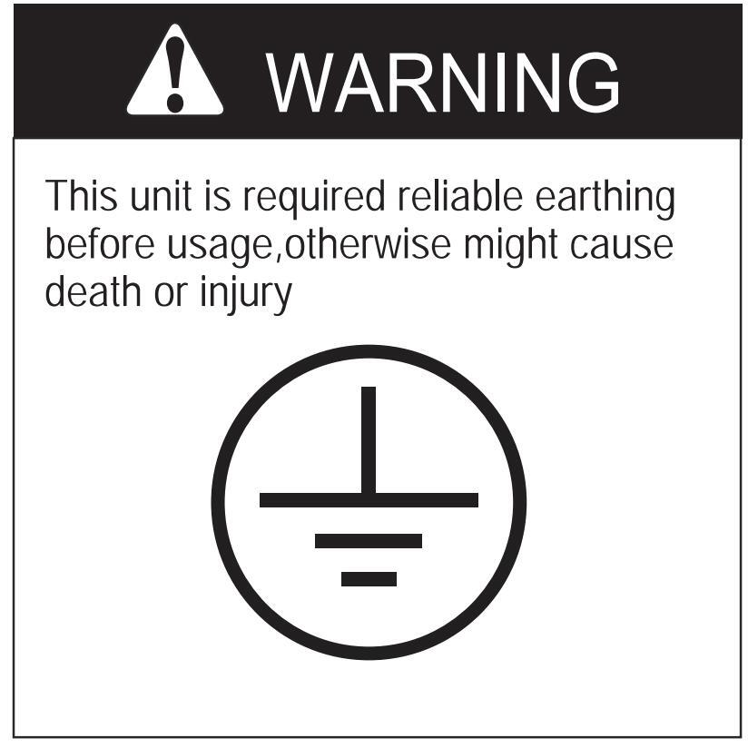
Please ask skilled service persons for reliable earthing connection
Your safety is the most important thing we concerned !
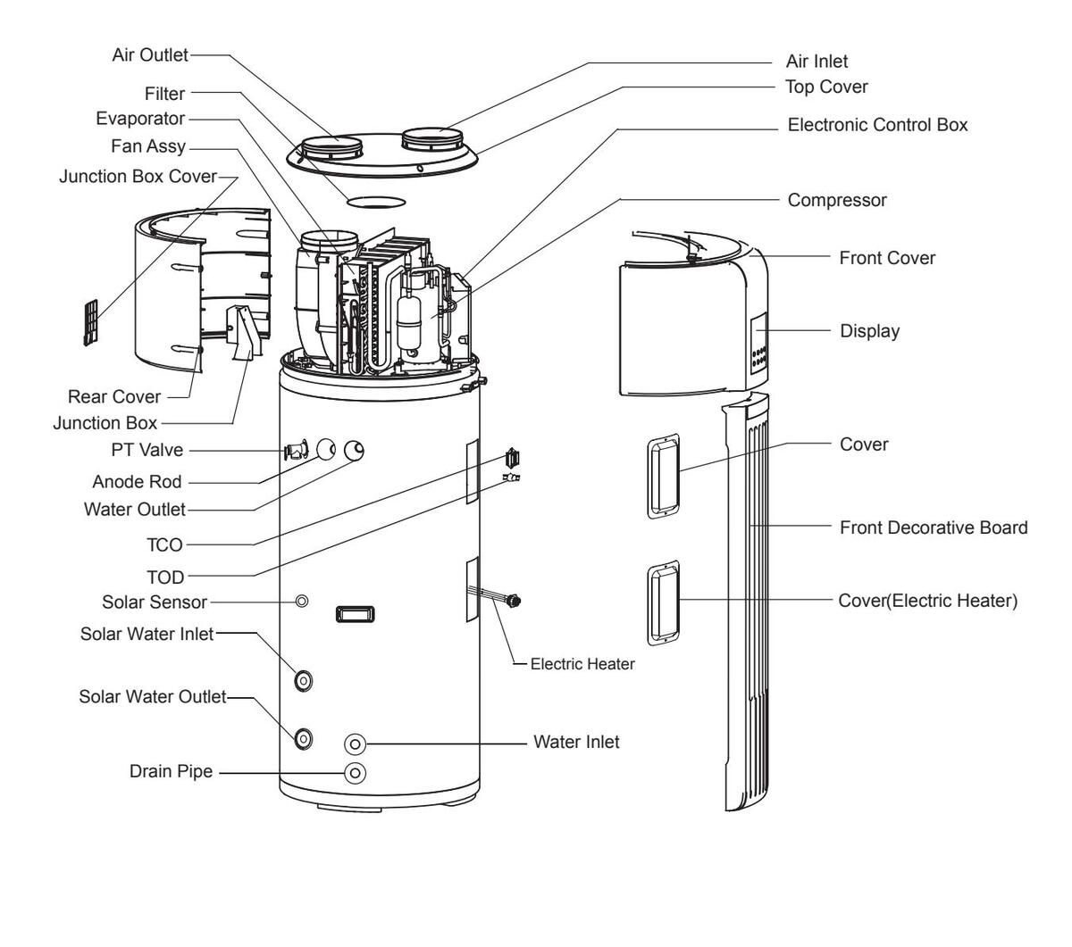
PARTS NAMES
| NOTE |
|---|
|
All the picture in this manual are for explanation purpose only. They may be slightly different from the heat pump water heaterr you purchased (depand on mode). The actual shaped shall prevail. |
CONTENTS
PAGE
| PRECAUTIONS | 1 |
|---|---|
| ACCESSORIES | 2 |
| INSTALLATION LOCATION | 2 |
| INSTALLATION | 3 |
| PIPELINE CONNECTION | 4 |
| DUCT CONNECTION WAY | 5 |
| ELECTRIC CONNECTION | 6 |
| OPERATING INSTRUCTION | 8 |
| RUNNING AND CAPABILITY | 14 |
| MAINTENANCE | 16 |
| SPECIFICATIONS | 17 |
1. PRECAUTIONS
To prevent injury to the user or other people and property damage, the following instructions must be followed. Incorrect operation due to ignoring of instructions may cause harm or damage.
The safety precautions listed here are divided into two categories. In either case, important safety instructions are listed to which close attention must be paid

WARNING
Failure to observe a warning may result in death or serious Iniury.

CAUTION
Failure to observe a caution may result in injury or damage to the equipment.
Â
WARNING
The water heating unit must be earthed effectively .
- A creepage breaker must be installed near the power supply
- Do not tear off the labels on the units for the purpose of warning or reminding
WARNING
- Ask the professional installer for installation of the air source heat pump water heating units, improper installation may result in water leakage, electric shock or fire.
- Ask the professional service person for the repair and maintenance. Improper repair and maintenance may result in water leakage, electric shock or fire
- In order to avoid electric shock, fire or injury, if any abnormality is detected, such as smell of fire, turn off the power supply and call your service agent for instructions.
- Never use the wire and fuse with wrong rated current.. Use of wrong wire or fuse may cause the unit to break down or a fire.
- Do not insert fingers, rods or other objects into the air inlet or outlet. When the fan is rotating at high speed, it will cause injury.
-
Never use a flammable spray such as hair spray, lacquer
- paint near the unit. It may cause a fire.
- Never touch the air outlet or the horizontal blades while the swing flap is in operation. Fingers may become caught or the unit may break down.
- Never put any objects into the air inlet or outlet. Objects touching the fan of high speed can be dangerous.
- Do not dispose this product as unsorted municipal waste.Collection of such waste separately for special treatment is necessary.
- The appliance shall be installed in accordance national wiring regulations.
- The appliance should not be used by children without supervision.
- If the supply cord is damaged, it must be replaced by the manufacturer or its service agent or a similarly qualified person in order to avoid a hazard.
- An all-pole disconnection device which has at least 3mm separation distance in all pole and a residual current device(RCD)with the rating of above 10mA shall be incorporated in the fixed wiring according to the national rule.
- DISPOSAL: Do not dispose this product as unsorted municipal waste. Collection of such waste separately for special treatment is necessary. Do not dispose of electrical appliances as unsorted municipal waste, use separate collection facilities. Contact you local government for information regarding the collection systems available.
- If electrical appliances are disposed of in landfills or dumps, hazardous substances can leak into the groundwater and get into the food chain, damaging your health and well-being.
1
CAUTION
- The earth pole of terminal must be earthed, and the rated current should be more than 10A. Make sure that power supply terminal and power supply plug are dry enough and have a good connection. Method: Turn on power supply run the unit for half a hour then turn it off and check whether the power supply plug is hot or nor.If it's hot (more than 50°C), please change it with a new and eligible one, or it may result in an electric shock or fire. Do not use the air-source water heater for other purposes
- Before cleaning, be sure to stop the operation and turn the breaker off or pull out the power cord. Otherwise, an electric shock and injury may be caused.
- The hot water probable need to mix with cold water too hot water (over 50°C) in the heating unit may could injury.
- In order to avoid injury, do not remove the fan guard on the outdoor unit.
- Do not operate the air-source water heater with a wet hand. An electric shock may be caused.
- The installation height of power supply should be over 1.8m, if any water may spatter. And safe from water.
- In the water inlet side, the One Way valve must be installed.
- It's normal if some water drops from the hole of PT valve during operation.Bit, if the water is in a great amount, call your service agent for instructions.
After a long term use, check the unit stand and fittings. If damaged, the unit may fall and result in injury.
Arrange the drain hose to ensure smooth drainpipe. Improper drainpipe may cause wetting of the building, furniture etc.
Do not touch the inner parts of the controller. Do not remove the front panel. Some parts inside are dangerous to touch, and a machine malfunction may be caused.
Do not turn off the power supply.
System will stop or restart heating automatically. A continuous power supply for water heating is necessary, except service and maintenance.
2. ACCESSORIES
Table, 2-1
| Accessory Name | Qty. | Sharp Purpose | |
|---|---|---|---|
|
Owner's & Installation
Manual |
1 |
Installation and use instruc
This manual |
|
| Y-shaped Filter | 1 | ₽ | To filtrate inlet water |
| One Way Valve | 1 | 6 -3 |
Prevent water from
flowing back |
| Adaptor | 1 | Drain condensate water | |
3. INSTALLATION LOCATION
- Enough space is installation and maintenance shall be preserved.
- The air inlet and outlet should be free from obstacles and strong wind.
- The bearing surface should be flat able to bear weight of the unit and suitable for installing the unit without increasing noise or vibration.
- The operation noise and air flow expelled shall not affect neighbors.
- No flammable gas is leaked nearby.
- It is convenient for piping and wiring
- If it is installed in indoor space, it might cause indoor temp declined and noise disturbance, Please take preventive measures for this.
- If the unit need to be installed on a metal holder, make sure they are insulated well and in accordance with local standard.
A
CAUTION
- Installing the equipment in any of the following places may lead to malfunction of the equipment (if it is inevitable, consult the supplier).
- The site contains mineral oils such as cutting lubricant.
- Seaside where the air contains much salt
- Hot spring area where corrosive gases exist, e.g., sulfide gas
- Factories where the power voltage fluctuates seriously.
- Inside a car or cabin.
- Place like kitchen where oil permeates.
- Place where strong electromagnetic waves exist.
- Place where flammable gases or materials exist.
- Place where acid or alkali gases evaporate.
- Other special environments.
- Precautions before installation
- Decide the correct way of conveying the equipment.
- Decide the correct way of conveying the equipment.
- If the unit has to be installed on a metal part of the building, electric insulation must be installed, and the installation must meet the relevant technical standards for electric devices.
- Installation space
Before installing the unit, reserve the space of maintenance shown in the following figure.
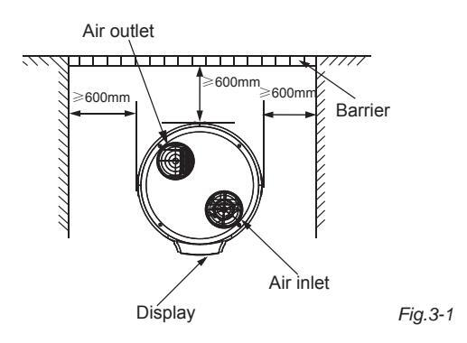
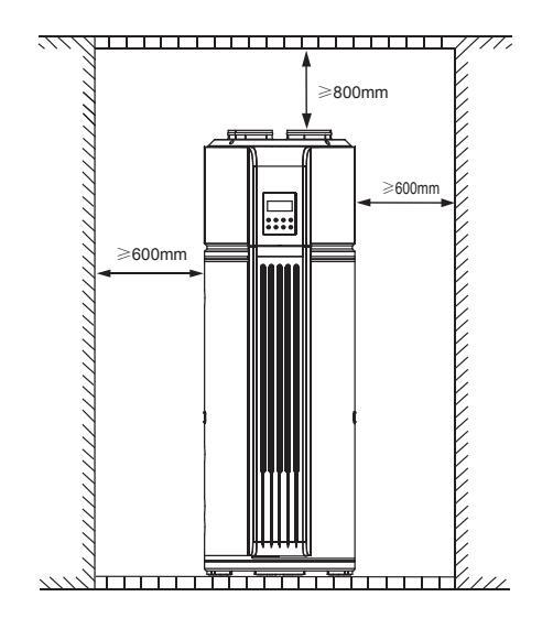
Fig.3-2
4. INSTALLATION
WARNING
- Ask your supplier to install the air source heat pump water heating units. Incomplete installation performed by yourself may result in a water leakage, electric shock, or fire.
- The place without direct sunlight and other heat supplies. If there's no way to avoid these, please install a covering.
- The unit must be securely fixed, or else, noise and shaking will be resulted.
- Make sure that there's no remora around the unit
- In the place where there is strong wind like seashore, fix the unit in the location protected from the wind.
- Carry the unit onto the site
- In order to avoid scratch or deformation of the unit surface, apply guard boards to the contacting surface.
- No contact of fingers and other things with the vanes
- Don't incline the unit more than 45° in moving, and keep it vertical when installing.
- This system is very heavy, it need to be carried by 2 or more persons, othewise might cause injury and damage.
- Install the unit.
- The circulating air for every unit should be more than 700m3/h.
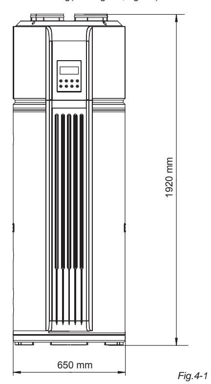
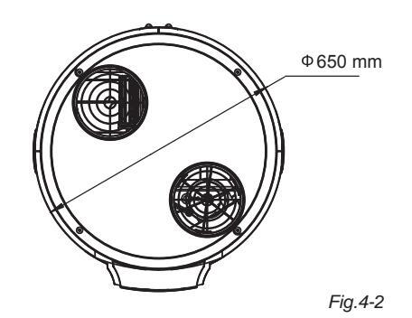
- Make sure there is enough Installation space.
- Outline dimensional drawing(see Fig.4-1, Fig.4-2 )
Installation 8 Owner's Manua
5. PIPELINE CONNECTION
Pipeline Connection Sketch
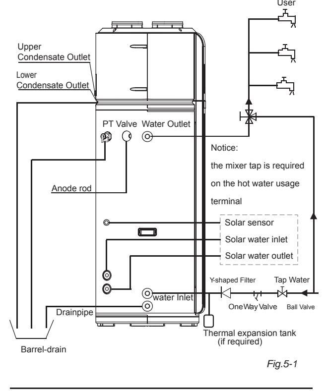
When install the main unit, please set a drain valve at the drain orifice of the unit by self.
Pipeline Connection Explanation
- Installation of the water inlet or outlet pipes: The spec of the water inlet or outlet thread is RC3/4" (internal thread). Pipes must be heat-resistant and durable.
- Installation of the pipe for PT valve: The spec of the valve connecting thread is RC3/4" (internal thread). After installation, it must be confirmed that the drainpipe outlet is exposed in the air. When flexible drainpipe is jointed to the pressure relief orifice of this valve, it must be confirmed that the flexible drainpipe is downwards vertically and exposed in the air.
Installation & Owner's Manual
NOTE
A safety valve should be installed at the water inlet of the unit. Arrange water pipes and which connected fittings as illustration of the above figure. In case of install it at a place where outside temperature below freezing point, insulation must be provided for all hydraulic components.
•The handle of PT Valve should be pulled out once per half year, to make sure that there is no jam of the valve.
Please beware of burn, because of the high temperature of water. The drainage pipe should be well installed ,in order to avoid freezing up in cold weather.
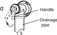
-
Do not press the handle of PT Valve
Do not dismantle the PT Valve,
- Do not block off the Drainage pipe.
It will cause explosion and injury, if do not comply with the above instruction.
- Installation of the One Way Valve: The spec of the One Way Valve thread in accessories is RC3/4". It is used to prevent backflow of water.
- Installation of the Y-shaped filter: The spec of the Y-shaped filter thread in accessories is RC3/4". It is used to filtrate inlet water.
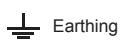
- After all the pipes installed turn on the cool water inlet and hot water outlet and start effusing the tank. When there is water normally flowing out from water outlet, the tank is full. Turn off all valves and check all pipes. If there is any leakage, please repair.
- If the inlet water pressure is less than 0.15MPa, a pressure pump should be installed at the water inlet. For guarantee the long safety using age of tank at the condition of water supply hydraulic higher than 0.65MPa, a reducing valve should be mounted at the water inlet pipe.
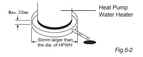
- Probably may cause water leakage because of blockage during the drainage, pit is suggested to use a water collector as instruction in Fig 5-2 .
Solar Energy Coil Electrical Control Instruction
The mainboard of machine has two dedicated ports use for connecting to the solar thermal, they are CN17 ON/OFF port and CN18 Feedback port. The ports ensure heat pump and solar thermal won't work together.
■ Among them, the CN17 ON/OFF port is used for receiving the control signal of the solar energy water heating system, this signal needs to be voltage free switch signal. When the control signal is closing signal, the heat pump system will be locked and can't open to heat; when the control signal is open circuit signal, the heat pump system will be relieved its locked state, and the unit will judge to open or shut down according to the unit's own condition.
■ The CN18 Feedback port is used to send the feed backing of open/stop situation to the solar thermal, this port feeds back the high and low level signals. When both sides of the terminal is low level (0V) for outlet, means that the heat pump unit is under open state; when both sides of the terminal is high level (5V) for outlet, means that the heat pump unit is under shut down state.
Which need to be declared is that the heat pump unit only receives and provides the above two signals, the control software needs to be wrote according to the entire water heating system control while designing the project installation.
■ Be caution, as the water tank can automatic recover temperature protection switch TCO when operating temperature is 78°C, and the operating temperature for the manual recover temperature protection switch is 85°C, when the water temperature of the solar thermal which enter the water tank coil is over heated (higher than the operating temperature of the TCO), it will lead to TCO operates and every part of the machine loads, include the power of the main control board, the display screen will be cut off, so please be sure the water temperature of the solar thermal which enter the water tank coil won't be over heated.
Fig. 6-1
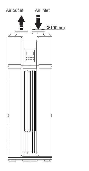
6. DUCT CONNECTION WAY
Air inlet and outlet no need to connect with canvas
Note: Upon connect canvas, portion airflow and capacity in heat pump system will lose in the system.
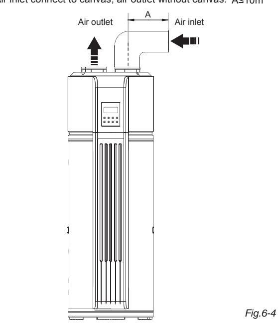
■ Air inlet without canvas, air outlet connect to canvas. A≤10m
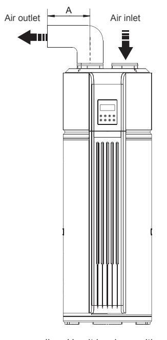
Fia.6-3
Recommending: Use it in where with surplus heat or indoor place in the winter where with surplus heat.
■ Air inlet and outlet need to connect with canvas. A+B≤10m
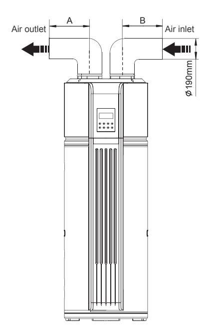
■ Air inlet connect to canvas, air outlet without canvas. A≤10m
Recommending: In summer, use this connection way could charge flesh air into room.
Canvas Duct Description
| Canvas Duct | Round canvas duct | Rectangle canvas duct | Other shaped canvas duct |
|---|---|---|---|
|
Dimension
(mm) |
Dimension ⊕190
(mm) |
||
|
Straight-line
pressure drop (Pa/m) |
≤2 | ≤2 | |
|
Straight-line
length (m) |
≤10 | ≤10 | Refer to above data |
|
Bent pressure
drop(Pa) |
≤2 | ≤2 | |
| Bent's qty. | ≤5 | ≤5 | |
V
Canvas duct to be connected at air outlet better than at inlet.
NOTE
| WARNING |
|---|
| Linen connect convex nortion cirflew and |
Upon connect canvas, portion airflow and capacity in heat pump system will lose in the system.
- For the case of main unit connect with canvas, the diameter of the duct must ≥190mm, total length of the ducts should not longer than 10m or the maximum static pressure should not exceed than 50Pa. Be in mind of the bending site of the duct no more than 5.
- For main unit air outlet connects with canvas, when main unit operating, condensate dew be generates at the outside of air outlet canvas. Please pay attention to the discharge of condensate water. We suggest you to wrap the thermal insulated layer at the outside of air outlet canvas.
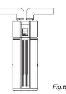
- Recommending install the main unit at indoor ambient. It is not allow to install the unit at outdoor or rain achieving place.
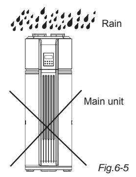
- Warning: In case of rain entering to internal components of the main unit, the component might be damaged or causing physical danger.( Fig.6-5 )
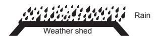
- In terms of the main unit connect with canvas reaching to outdoor, a reliable water-resistant measure must be conduct on the duct, resist water drop into internal of the main unit.( Fig.6-6 )
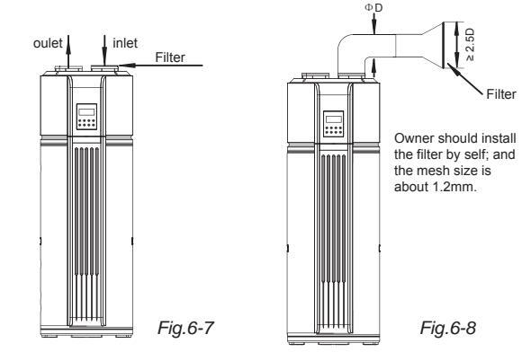
■ Filter installing at the main unit inlet. In terms of the main unit connect with canvas, filter in there must be put forward to the air inlet of duct. ( Fig.6-7/6-8 )
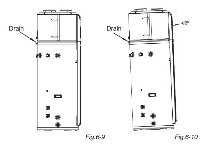
To fluently drain condensate water from evaporator, please install the main unit at a horizontal floor. Otherwise, please ensuring the drain vent is at the lowest place. Recommending the inclination angle of unit to the ground should no more than 2°.
Installation & Owner's Manual
7. ELECTRIC CONNECTION
- The power supply for the unit must be specialized according to the rated voltage.
- Earthing must be included in the power circuit. And it must be connected with the effective external ground wire.
- The wiring must be performed by professional technicians according to the circuit diagram.
- Set the electric leakage protector according to the relevant electric technical standards of the State.
- The power cord and the signal cord shall be laid out neatly and properly without mutual interference or contacting the connection pipe or valve.
- After wire connection is finished, check it again and make sure the correctness before supplying power.
7.1 Specifications of Power Supply
Table. 7-1
| Model Name SWH-35/300TS | |||
|---|---|---|---|
| Power Supply | 220-240V~50Hz | ||
|
Mlin. Diameter of Power
Supply Line(mm2) |
4 | ||
| Earth Wire(mm2) | 4 | ||
| Manual Switch(A) Capcity/Fuse | 32/25 | ||
| Creepage Breaker | 30 mA ≤0.1sec | ||
- Please choose the power cable according to above table, and it should comply with local electric standard.
- The power cord type designation is H05RN-F.

WARNING
Just to be on the safe side, the unit must be installed an Creepage Breaker near the power supply and must be effectively earthed.
7.2 Electric Wiring Illustration
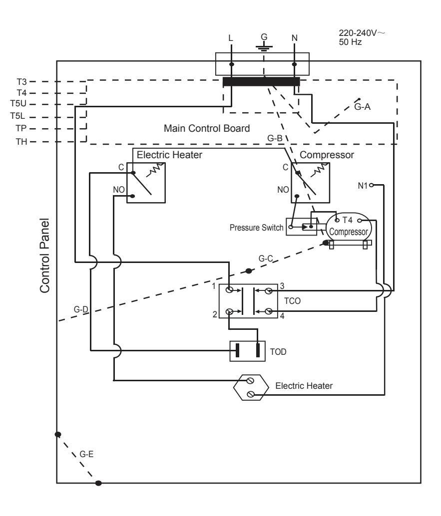
T3: Tube Temp. Sensor T4: Ambient Temp. Sensor T5U: Tank Temp. Sensor (upper) T5L: Tank Temp. Sensor (lower) TP: Discharge Temp. Sensor(upper) TH: Return air temperature sen

8. OPERATING INSTRUCTION
8.1 Operation steps
Before using this unit, please follow the steps below.
Water Affusion: If the unit is used for the first time or used again after emptying the tank, please make sure that the tank is full of water before turning on the power. Method: see Fia.7-1
CAUTION
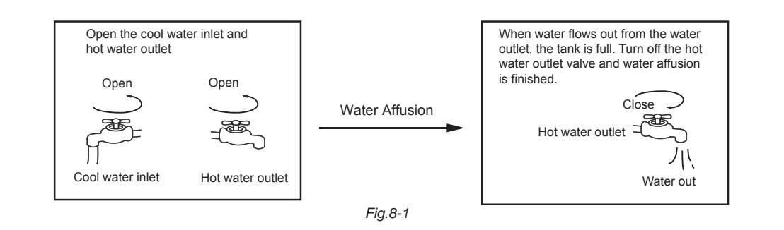
Operation without water in water tank may result in damage of auxiliary e-heater. Due to such damage, the supplier is not responsible for the quality issue.
After powered on, the display lights up. Users can operate the unit through the buttons under the display for different modes

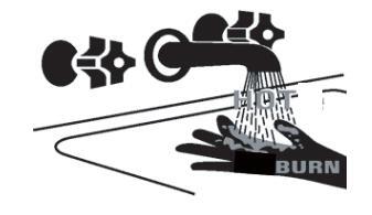
Over 50°C may result in serious burn or so caused death. Special care should be paid to the children, the disabled and the old in case of water burn
Emptying: If the unit needs cleaning, moving etc, the tank should be emptied. Method: See Fig.8-2 :
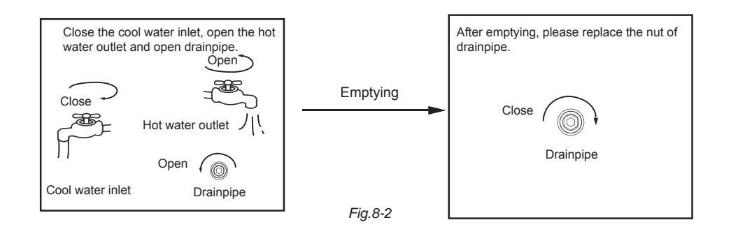
8-2 Operation steps
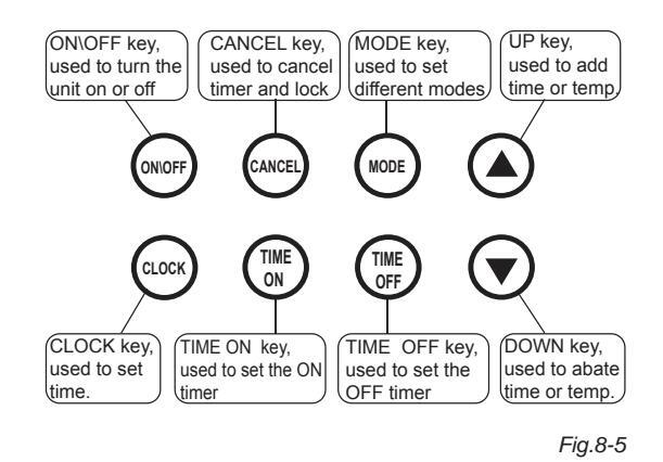
1 Control Panel Explanation
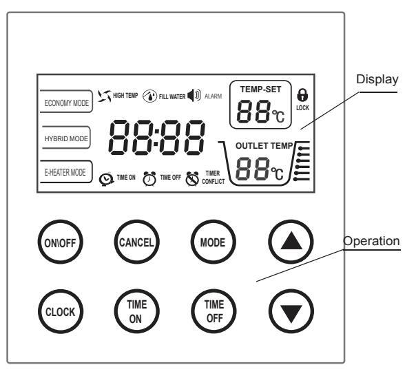
Fig.8-3
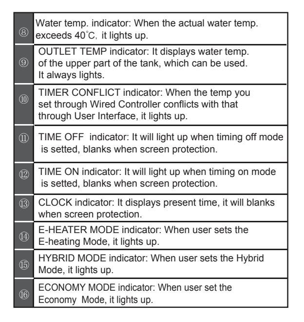
2 Display Explanation
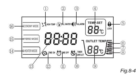
Table. 8-1
| 1 | HIGH TEMP indicator: When the setting temp. exceeds 50°C, it lights up to remind you that the outlet temp. is too high for direct spray. |
|---|---|
| 2 | FILL WATER indicator: When the power supply is turned on, it lights up to remind you to re-affuse water. |
| 3 | ALARM indicator: It will flashing at the malfunction or protection time. |
| 4 |
TEMP-SET indicator: Show the setting temperature and
blank when screen protection. Codes are show at the malfunction or protection time |
| 5 | LOCK indicator: When the UI is locked, it always lights. |
| 6 | Water temp. indicator: When the actual water temp. exceeds 60°C, it lights up. |
| 7 | Water temp. indicator: When the actual water temp. exceeds 50°C, it lights up. |
3 Operation
4 Operation Instruction
Preparation before running the unit.
When you run the unit for the first time, all the indicators on the UI will light for 3 second, and the buzzer will "didi" ring twice at the same time, and then, display the fiducial web page. After no operation for 1 minute, all indicators will go out automatically except Water fill indicator flashing and tank's temp. indicator lighting. Buzzer will "di" ring when you press it.
When the tank is full, please press the ON\OFF key, the Water fill indicator will stop flashing and you can continue to function other settings. When all settings finished, please press the ON\OFF key again and the Water fill indicator will go out. And then run the unit.
When the unit is running, if there is no operation or malfunction for 20s, the backlight of the display will go out automatically except operation model,outlet temp.lock indicator.
If there no operation for 1min, the unit will lock automatically. but the lock indicator would be right all time.
Disinfection mode- unit will automaticly run disinfection mode every Friday at 23:00PM.
Display panel indicates this mode by showing "CL"
Lock and Unlock
In order to prevent wrong operation, a special lock function has been designed. If there is no operation for 1min, the unit will be locked automatically, and display the lock indicator . When the unit is locked, no keys can be operated.
Unlock
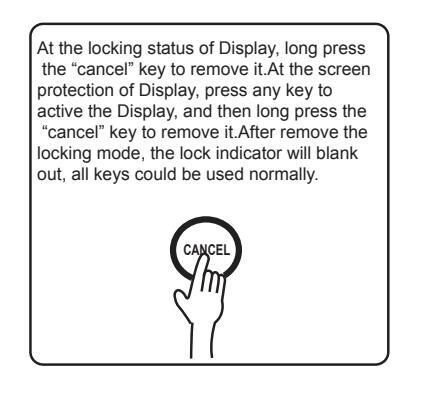
Fia.8-6
Clock Set
The clock is for a 24-hour system and the initial time is 00:00. To make a better use of this unit, it is recommended to set the time for accurate local time. Every time powered off, the clock will be reset to the initial time 00:00.
Method for time set
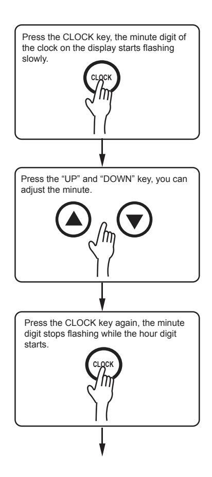
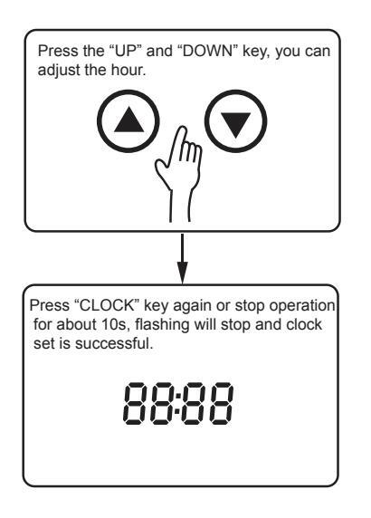
Fig.8-7
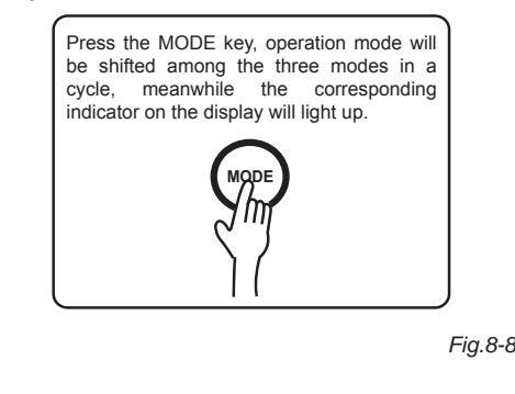
Mode Selection
- The unit is enhanced with three operation modes, Economy Mode, Hybrid Mode and E-heater Mode.
- Economy Mode: The unit heats water only by compressor drive according to heat-pump principle. Used when the ambient temp. is high.
- Hybrid Mode: The unit heats water not only by compressor drive but also by electric heater. Used when the ambient temp. is low or large amount of hot water is needed.
- E-heater Mode: The unit heats water only by electric heater. Used when the ambient temp. is very low.
- By default, the unit operates in Hybrid Mode.
- Change:
Temp. Set
Temp displayed is the water temp. in the upper part of the tank. Default is 55°C and the Economy mode setting range is 38~60°C, the Hybrid and E-heater mode setting range is 38~60°C.
Method for set
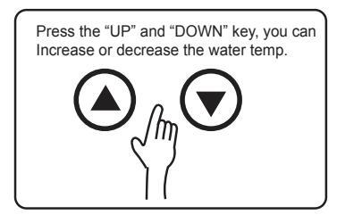
Fig.8-9
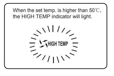
Fig.8-10
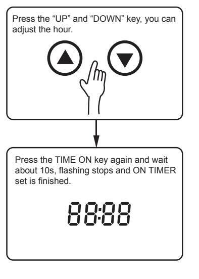
Fig.8-11
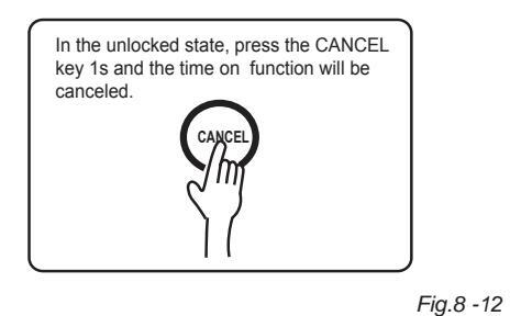
Cancel:
Timer
User can set up a running start time and a stop time on a specifically by the timer function. The least numbers of timer is ten minutes.
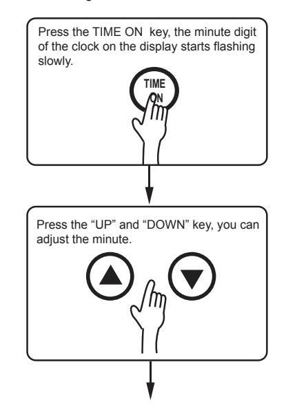
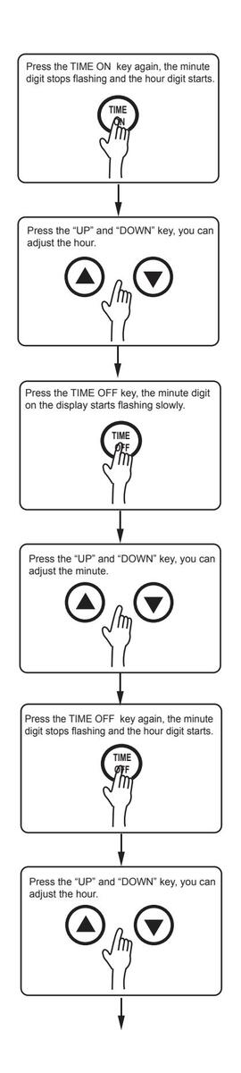
Time on: User can set up a start time by this. The unit will auto run one time between the set time and 24:00 on the same day. Method for set
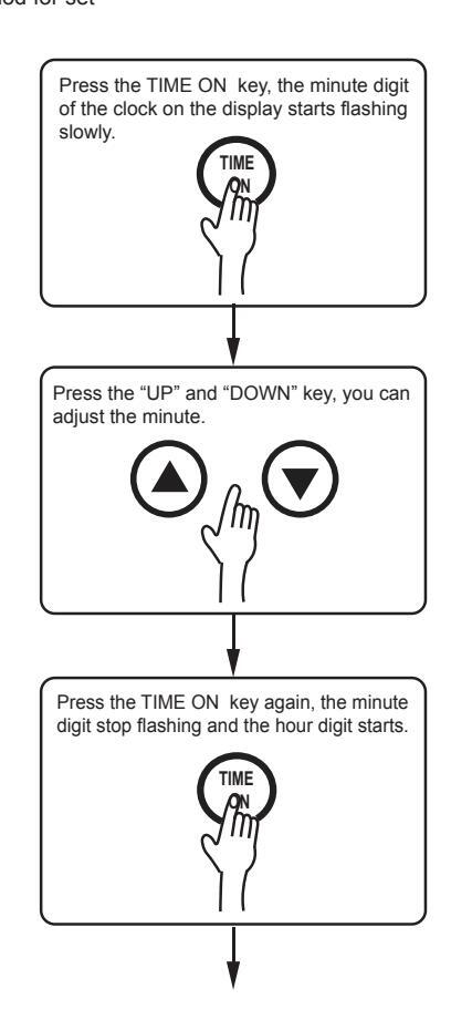
- Time on and Time off: Users can set up a running start time and a stop time. When the start time is earlier than the stop time, the unit will run between the set time. When the start time is later than the stop time, the unit will run between the start time today and the stop time next day, when user set up on a running start time and a stop time at the same time, the stop time will be delay ten minutes automatically.
- Method for setting
|
Stop operation for about 10s, flashing
stops and TIME ON+TIME OFF set is finished. |
|
|---|---|
| 88:88 | |
| Fig.8-13 | |
| Cancel |
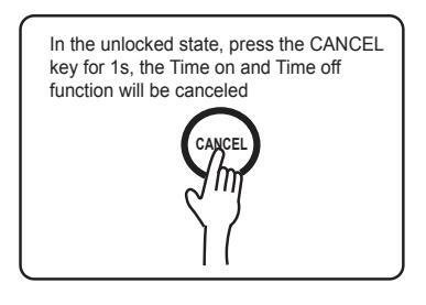
Fig.8-14
P
Time on and Time off can not be set to the same time. If they are the same, the stop time will delay 10 minutes automatically. For example, Time on and Time off set to 1:00 at the same time, then the stop time will adjust to 1:10 automatically.
NOTE
Time off function can not be used alone. The key can be used only after setted the on time. User can press the on\off key manual beyond the timer range.
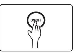
Power On and Power Off
Press Power On/Power Off button after all the above have finished and the system will run as the setting. And simply press the same button to stop it.
Fia.8-15
Operation status
• The LA code from the screen of set Temp. will appear and remind user when ambience temp. not meet the operation condition of heat pump unit(beyond -7~43°C), User can switch the economy mode to E-heating mode in sure of enough volume of hot water if need, The unit will return operation pre-status automatically in no any operation when the ambience temp. meet the operation condition of heat pump mode and the error LA will be disappear at the same time,the screen display nomally.
Installation & Owner's Manual
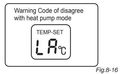
In case of continual 20 hours when in the season ambient temperature doesn't meet for the heat pump operation requirement (absent from the range -7~43°C), "LA" will display at Temp. Settings window and ALARM indicator flashing simultaneously alarming that the temperature doesn't suit for heat pump performance, only E-heating mode could be set at such circumstance. Please switch to E-heating mode manually for ensuring there's adequate hot water could be supplied, if that so code is going to disappear and indicator alarm stop flashing any more, all recover to be normal.
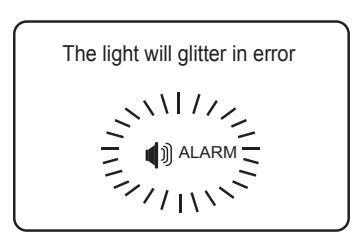
Fig.8-17
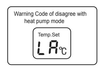
Fig.8-18
-
Error Shooting
- If some errors happen, the buzzer will buzz 3 times every other minute and the ALARM indicator will glitter fast. Press CANCEL for several seconds to stop the buzzer but the light will keep glittering.
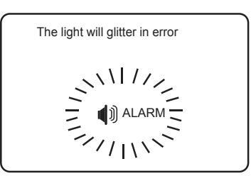
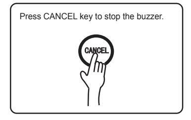
Fig.8-19
The error code from the screen of set Temp. will display when malfunction happen, the system display error code after one minute when press the key again and the screen display set temp.
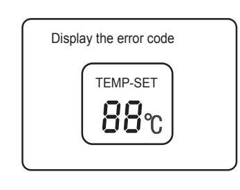
Fia.8-20
When the economy mode happen malfunction, the system can keep using after switching to E-heater mode; When some error happens, though the system could be used in some circumstances, it could not reach the expected efficiency. Please contact your supplier for help.
Error Code Explanation (See table. 8-20)
WARNING
The covers of the E-heater should not be opened
without guidance of professional technician, in case of electric shock or any danger.
Table 8-2
| Display | Malfunction Description | ||
|---|---|---|---|
| E0 | Error of sensor T5U | ||
| E1 | Error of sensor T5L | ||
| E2 | Tank and Wired Controller communication error | ||
| E4 | Evap. pipe temperature sensor error | ||
| E5 | Ambient temperature sensor error | ||
| E6 | Discharge pipe temp.sensor error | ||
| E7 | Heat Pump system error | ||
| E8 | Electric leakage protection | ||
| E9 | TH sensor condenser failure | ||
| P1 | System high pressure protection | ||
| P2 | Discharge pipe temperature overhigh protection | ||
| P3 | No current flowing in Compressor | ||
| P4 | Compressor overloaded protection | ||
| P8 | No current flowing in electric heater | ||
| P9 | Upper e-heater overloaded protection | ||
| LA | Ambient temp. is not fit for heat pumps, change the mode to E-heater mode | ||
If the errors happen, please contact the supplier or after-sale service.
9. RUNNING AND CAPABILITY
9.1 Trial Running
- Before running, please check the following items first:
- Correct installation of the system;
- Correct connection of pipeline and wiring;
- Leakage of the refrigerant pipeline tested:
- Efficient drainpipe;
- Complete insulation protection:
- Correct earthing;
- Correct power supply;
- No obstacle outside the air inlet and outlet;
- No air in the water pipeline and all valve opened;
- Effective electric leakage protector;
- Sufficient inlet water pressure(≥0.15MPa)
9.2 Operating Capability
- Water-heating Operating Capability
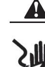
- Heating elements are included in the unit, one heat pump and one electric heaters and solar coil. All these three heating elements do not work together. This unit has two temp. sensors, which are installed at the upper 1/4 and bottom 1/2. The upper one tests the upper temp., the figure shows in the water temp. table, and the bottom one is used to test the lower water temp., which will control the ON & OFF of the unit, no shows in the display panel.
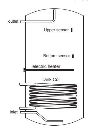
Fig.9-1
- Economy Mode: In this mode, according to the water temperature setting, heat pump in preference to electric heater. (Water outlet temp. range 38~60°C, running ambient -7~43°C)
- Hybrid Mode: In this mode, the system will adjust the working capabilities of e-heater and heat pump according to the tank water temperature.
(Water outlet temp. range 38~60 °C, running ambient -30~43 °C)
Installation & Owner's Manual
E-heater Mode: In this mode, the compressor and the fan motor will not run but the e-heater work only. (Water outlet temp. range 38~60°C, running ambient -30~43)
°C ).
| NOTE |
|---|
In the E-heat mode, only half tank of water, i.e. 150L, could be heat every time.
Defrosting during Water-heating
- In the Economy Mode and Hybrid Mode, if the evaporation frosts in a cold circumstance, the system will defrost automatically to keep effective performance(3~10 min).
- Ambient Temperature
The system's operation temperature is within -30~43°C and below are the operation temperature for each mode.
1) Economy Mode: -7~43℃
NOTE
This mode should be used at the ambient temperature maintaining at -7~43°C. While the ambient temperature below than -7°C, the energy efficient would bocome low obviously, we recommend you to using the E-heat mode at this circumstance.
2) Hybrid Mode: -30~43°C
3) E-heater Mode: -30~43°C
Mode Selection
Different mode is designed to meet different demand and the following are recommended selections.
- Economy Mode:-7~43℃, a continuous hot water demand below 250L(60℃);
- Hybrid Mode: -30~43℃, a continuous hot water demand between 300L~350L(60℃);
- E-heater Mode: -30~43°C, a continuous hot water demand between 150L(60°C).
- Self-Protection Apparatuses
- When the self-protection happens, the system will be stopped and start self-check, and restart when the protection resolved;
- When the self-protection happens, the buzzer will buzz in every other minute, the ALARM indicator glitter and the display indicate the error code and water temperature alternatively. Press CANCEL button for 3sec to stop the alarm. All stop when the protection is resolved and error code disappears on the display.
- In the following circumstances, self-protection starts:
- Air inlet or outlet is obstacled;
- 2 The evaporation is covered with too much dust;
- ③ Incorrect power supply (exceeding the range of 220-240V)
When self-protection happens, cut the power supply manually and restart after the error resolved.
NOTE
- Water Temperature Display
- The temperature on the display is the water temperature in upper part of water tank (over 1/4) which you will use, but not that of all the water.
- The 6 indicators beside the water temperature on the display are the lower part water temperature. When the temperature is higher than 40°C, the blue one will light up; when higher than 50°C, the blue and yellow ones light up; when higher than 60°C, the blue, yellow and red ones light up and when all light up, the water temperature has reached the set point.
- In water using, the temperature of the lower part may decrease while the upper part still keeps a high one, and the system will start heating the lower part. And it is normal.
- Error Shooting
- When common error happens, the system enters Standby Mode and could still work, but not so efficient as normal. Please contact the technician.
- When serious error happens, the system will be unable to carry on. Please contact the technician.
- When error happens, the buzzer will buzz in every other minute, the Warning light glitter and the display indicate the error code and water temperature alternatively. Press CANCEL button for 3sec to stop the alarm.
- Restart after Long Stop When the system is started after a long time (trial running included), it is normal if the outlet water is unclean. Keep the tap on and it will be clean soon.
- Heat-up Time
10. MAINTENANCE
10.1 Maintenance
- Check the connection between power supply plug and socket and ground wiring regularly;
- In some cold area (below 0°C), if the system will be stopped for a long time, all the water should be released in case of freezing of inner tank and damage of e-heater.
- It is recommended to clean the inner tank and e-heater regularly to keep an efficient performance.
- Check the anode rod every half year and change it if it has been used out. For more details, please contact the supplier or the after-sale service.
- It is recommended to set a lower temperature to decrease the heat release, prevent scale and save energy if the outlet water is sufficient.
- Clean the air filter every month in case of any affect on the heating performance.
- In terms of the filter set in air inlet directly (namely, air inlet without connect with canvas), the method of dismantle the filter is: anti-clockwise unscrew the air inlet ring, take out the filter and clean it completely. finally, remount it to the unit.
- Before shutting the system down for a long time, please:
- Shut down the power supply:
- Release all the water in water tank and the pipeline and close all the valves:
- Check the inner components regularly.
- How to Change the Anode rod
- Turn off the power, and turn off the water inlet valve.
- Open hot water tap, and decrease the pressure of the inner container.
- Open the temperature pressure valve, and drain out the water, until there are no water flow out of.
- Get off the anode rod according to instruction.
- Replace with a new one, and make sure effective sealed
- Open cold water valve until hot water flows out, and turn off the hot water tap.
- Restart and can be used normally
10.2 Non-error Malfunction
3-min Protection
With the power supplied, an immediate restart after the shutting down will have to wait 3 min as to protect the compressor.
- If self-protection happens and the system stops, check :
- When the power indicator lights up, if the system is forced to run while startup requirement has not been met:
- If the air outlet or inlet is jammed or strong wind blows to air outlet.
Defrosting
When it is humid and cold, the evaporate may defrost and the water-heating capacity decrease. And the system will stop heating water and start defrosting and then restart water-heating
- During defrosting, fan stops working, four-way valve reverses the flow direction, and compressor keeps working.
- The defrosting time varies from 3min to 10min according to the ambient temperature and the frost.
- Temperature Display
- When the system stops, a decrease of the temperature is normal as heat released. When it decreases to some point, the system will restart automatically;
- During water-heating, the displayed water temperature might still decrease or not increase for a period of time because of the heat exchange of the water. When the whole tank of water has reached the set temperature, the system will stop automatically.
10.3 Malfunctions and Resolutions
Table. 10-1
| Malfunction | Cause | Resolutions |
|---|---|---|
|
Outlet water
is cold. The display is dark. |
|
|
|
No hot
water from the outlet. |
|
|
|
Water
leakage |
The joints on the pipeline are not sealed well. | Check and reseal all the joints. |
10.4 After-Sale Service
If the unit runs to some malfunction or error, it should be shut down and power supply cut off. And then please contact your local service center or supplier for help.
11. SPECIFICATIONS
Table. 11-1
| Model | SWH-35/300TS | ||||||
|---|---|---|---|---|---|---|---|
| Mode | Economy Mode | Hybrid Mode | E-heater Mode | ||||
| W | ater-heating cap. | 3000W | 3000W | 3000W | |||
| R | ated power/AMPS | 1500W/6.5A | 4300W/18.7A | 3000W/13.0A | |||
| Power supply | 220-240V~ 50Hz | ||||||
| C | Dperation control | Auto/Man | ual startup, error alarm | ı, etc | |||
| Protection |
High-pressure Pro
Temp Controller&I |
tector, Over-load Prot
Protector, Electric Lea |
ector,
kage Protector, etc |
||||
| С | ompressor power | 850W | |||||
| E-heater power | 3000W | ||||||
| Regrigerant | R134a(1200g) | ||||||
| Outlet water temp. | Default 55°C,(38-60°Cadjustable) | ||||||
| Water side exchanger | Surface heat exchanger | ||||||
| Inlet pipe Dia. | DN20 | ||||||
| tem | Outlet pipe Dia. | DN20 | |||||
| sys | Solar water outlet | DN20 | |||||
| eline | Solar water inlet | DN20 | |||||
| ır pip | Drain pipe Dia. | DN20 | |||||
| Nate | PT valve Dia. | DN20 | |||||
| Max. pressure | 1.0MPa | ||||||
| Jer | Material | Hydrophilic aluminum fin, inner groove copper tube | e copper tube | ||||
|
chang
side |
Motor power | 80W | |||||
|
Exo
air : |
Outlet air type | , | /ertical upflow air sup | ply | |||
| Dimension | Ф650×1920mm | ||||||
| W | ater tank cap. | 300L | |||||
| Net weight | 123kg | ||||||
| Fu | sible link type | T5A 250VAC | |||||
|
The test conditions:
Test temperature 15/12℃(DB/WB), Water temperature from 15℃ up to 45℃. |
|||||||
Take-back of electrical waste Information for Users to Disposal of electrical and electronic equipment (private households)
Icon on the product or in the accompanying documentation means that used electric or electronic products must not be disposed together with domestic waste. For the correct disposal of the product hand it over to a place for take-back, where it is collected free of charge. By correct disposal of the product you can help to preserve valuable natural resources and help in preventing potential negative impacts to environment and human health, which could be consequence of incorrect disposal of waste. Ask for more details from local authorities, nearest collection point, in Waste Acts of respective country, in the Czech Republic in Act no. 185/2001 Coll., in the wording of later regulations. In case of incorrect disposal of this waste, a fine can be imposed according to national regulations.

Manufacturer: Sinclair Corporation Ltd., 1-4 Argyll Street, London W1F 7LD, UK
Supplier and technical support: Nepa, spol.s.r.o. Purkyňova 45 612 00 Brno Czech Republic www.nepa.cz
Toll-free info line: +420 800 100 285


 Loading...