

Page 1

USER'S MANUAL
EN
WIRED CONTOLLER
SWC-02
Page 2

“Originalinstructions”
IMPO
RTANT N
Read this manual ca
or operating your new air conditioning
unit. Make sure to save this manual for
futu
re r
efe
ence.
r
OTE:
r
efully befo
r
e installing
Page 3

User Notices
For correct installation and operation, please read all instructions carefully. Before
reading the instructions, please be aware of the following items:
(1) Prohibit installing the wired controller at wet or sunshine places.
(2) Do not knock, throw or frequently disassemble the wired controller.
(3) Do not operate the wired controller with wet hands.
(4) Do not remove or install the wired controller by yourself. If there is any
please contact our after-sales service center.
(5) The wired controller is a general model, applicable for several kinds of units.
Some functions of the wired controller are not available for certain kinds of units, more
details please refer to the owner’s manual of unit. The setting of such unavailable
function will not affect unit’s operation.
(6) The wired controller is universal. The remote receiver is either in the indoor unit
or in the wired controller. Please refer to the specific models.
question,
Page 4

Contents
1 Display ..................................................................................... 1
1.1 Appearance ................................................................................ 1
1.2 Instructions for Related Displayed Symbols ............................... 2
2 Buttons .................................................................................... 3
2.1 Button Graphics ......................................................................... 3
2.2 Function Instructions of Buttons ................................................. 3
3 Operation Instructions .............................................................. 3
3.1 Menu Structure........................................................................... 3
3.2 On/Off ........................................................................................ 5
3.3 Mode Setting .............................................................................. 5
3.4 Temperature Setting ................................................................... 5
3.5 Fan Setting ................................................................................ 5
3.6 Swing Setting ............................................................................. 6
3.7 Functions Setting ....................................................................... 8
3.8 Unit Status
3.9 Current Error View ..................................................................
3.10 Timer Setting .......................................................................... 15
3.11 Clock Setting .......................................................................... 20
3.12 Lock Setting ........................................................................... 21
View ....................................................................... 12
. 13
4 Installation Instructions .......................................................... 22
4.1 Parts and Dimension of Wired Controller ................................. 22
4.2 Installation Requirements ......................................................... 23
4.3 Installation Methods ................................................................. 23
4.4 Disassembly ............................................................................ 26
Page 5
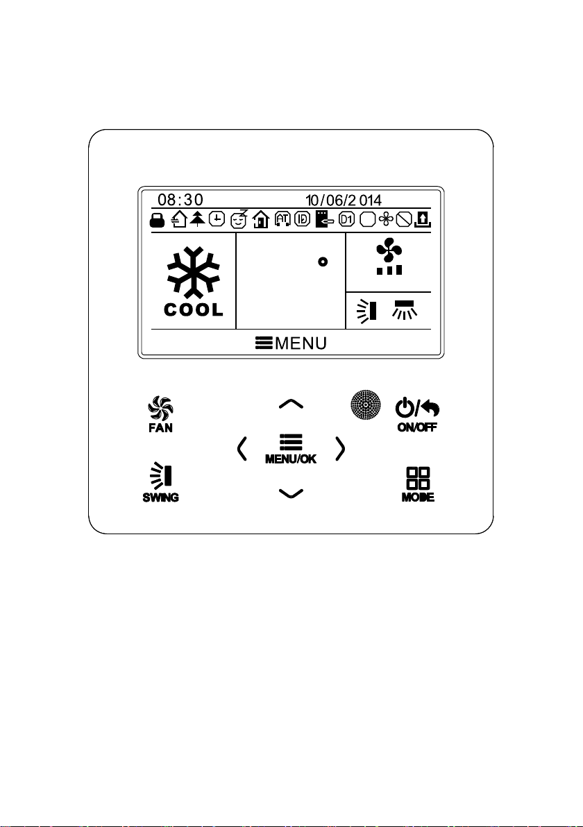
1 Display
1.1 Appearance
MON
$
SET
C
AUTO
26
Fig.1 Appearance of wired controller
1
Page 6

1.2 Instructions for Related Displayed Symbols
No. Symbols Instructions
1
2
3
4
5
6
7
8
9
10
11
12
13
14
15
16
Shielding status (Buttons, temperature, ON/OFF, mode or energy saving is
Up and down swing function
Left and right swing function
Fresh air function
Sleep function
Auto mode
Cooling mode
Dry mode
Fan mode
Heating mode
Health function
I-Demand function
Absence function
shielded by remote monitor)
Current set fan speed
Memory function (Memory in power failure)
DRED function
17
18
19
20
21
22
$
Gate card pulled-off status or nobody presented status
Save function
X-fan function
Timer on status
Quiet function
Function lock
2
Page 7
Buttons
2
2.
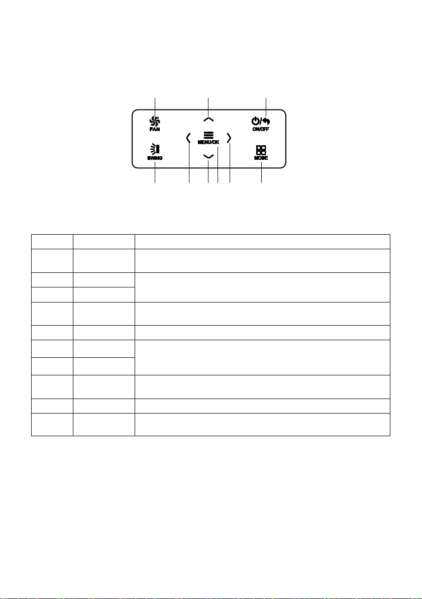
1 Button Graphics
1 2 3
4
2 Function Instructions of Buttons
2.
o. Button name Button Function
N
1 F
2
6
3
4
5
8
7
9 M
3 Ope
3.
1 Menu Structure
Norm
AN
∧
∨
ON/OFF/BACK
SWING Set up&down swing and set left&right swing
<
>
MENU/OK
ODE Set auto, cooling, dry, fan and heating modes for indoor unit.
Set low speed, medium speed,high speed, turbo and auto speed.
(1)
Set temperature
(2)
Set parameter
(3)
Move option cursor
(1) Turn on or turn off unit
Return to last page
(2)
Set related function on or off
(1)
Move option cursor
(2)
(3) Set parameter
Enter menu page
(1)
Confirm setting
(2)
ration Instructions
al setting of wired controller can be set directly on the main page, including
5 6 97 8
Fi
g. 2 Button graphics
fan speed, swing, set temperature, mode, ON/OFF. The setting and status view of
other functions can be set in corresponding submenu. Detailed menu structure is as
shown in Fig. 3.
3
Page 8
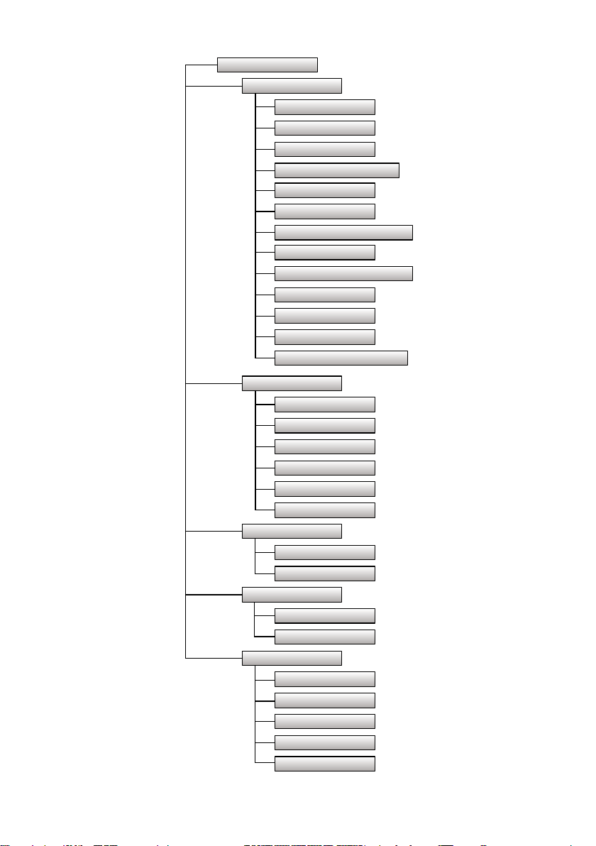
Main menu
User function menu
Fresh air function setting
Sleep function setting
Health function setting
I-DEMAND function setting
Absence function setting
Memory function setting
Fixed-angle swing function setting
Save function setting
Auxiliary heat function setting
Dry function setting
Quiet function setting
Air function setting
Fahrenheit Temperature Setting
Timer setting menu
Once
Daily
Weekly timer
Two week timer
Countdown timer on
Countdown timer off
Clock setting menu
Time format setting
Clock setting
View function menu
Unit status view
Current error view
Function lock menu
Unit ON/OFF lock
Mode setting lock
Temperature setting lock
Fan speed setting lock
Key lock
Fig. 3 Menu structure
4
Page 9

3.2 On/Off
When the wired control is on main page, press ON/OFF button to turn on the unit.
Press ON/OFF button again to turn off the unit. The interfaces of On/Off status are
shown in Fig. 4 and Fig. 5.
SET
26
MON
SET
C
26
MON
C
AUTO
Fig. 4 Off interface Fig. 5 On interface
3.3 Mode Setting
Under On status, pressing MODE button can set mode circularly as:
(COOLING) (DRY) (FAN) (HEATING)
(AUTO)
If save function is on, auto mode is not available.
Note:
3.4 Temperature Setting
Under unit on status, pressing “∧” or “∨” button on the main page increases or
decreases set temperature by 1℃(1℉); holding “∧” or “∨” button increases or
decreases set temperature by 1℃(1℉) every 0.3s.
In cooling,dry,fan and heating mode,temperature setting range is 16℃~30℃
(61℉~86℉). Under auto mode, set temperature cannot be adjusted.
3.5 Fan Setting
Under On status, pressing FAN button can set fan speed circularly as:
Low→Medium→High→Turbo→Auto→Low
Symbols displayed are as shown in Fig. 6.
TURBO AUTO
Fig. 6 Fan
setting
5
Page 10
3.6 Swing Setting
In unit on status, press SWING button for swing setting. Two swing modes are
available: fixed-angle swing and simple swing.
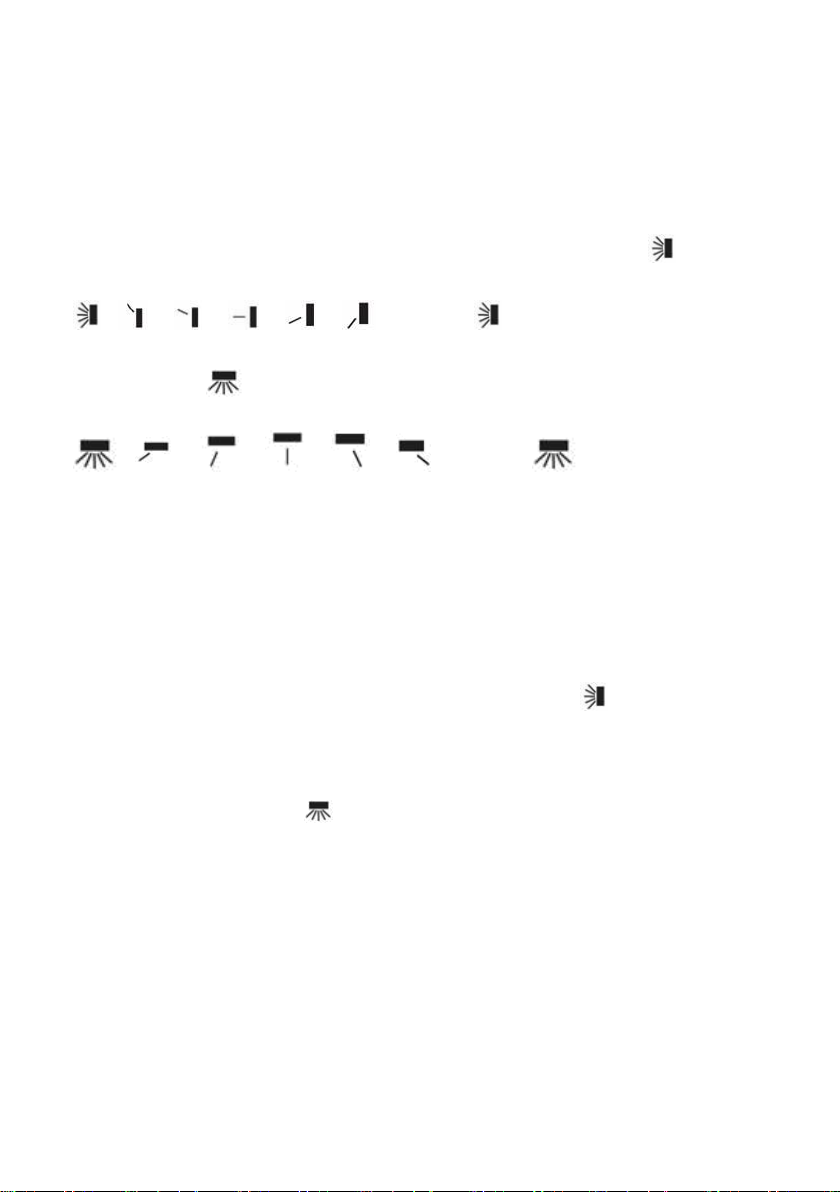
When fixed-angle swing mode is set, swing operation is as follows:
In unit on status, press SWING button to select up&down swing
swing angle will be adjusted circularly as below:
→ → → → → → closed →
Select up&down swing and left&right swing through “<” or “>” button. When
left&right swing
below:
→ → → → → → closed→
Note:
①.
Turn on fixed-angle swing mode in function setting page;
②.
If fixed-angle swing is not available for the model, fixed-angle swing will be
invalid when the wired controller turns on fixed-angle swing mode.
Simple swing mode: when fixed-angle swing mode is turned off, swing operation is
as below:
Pressing SWING button under unit on status, up&down swing frame occurs. Then
press SWING button to turn on or turn off up&down swing.
up&down swing is on and is not displayed when up&down swing is off. When up&down
swing frame have not disappeared, press “<” or “>” button to switch to left&right swing
setting. Then left&right swing frame occurs. In this case, press SWING button to turn on
or turn off left&right swing.
displayed when left&right swing is off. For detailed operation, please refer to Fig. 7.
is selected. Left&right swing angle will be adjusted circularly as
is displayed when
is displayed when left&right swing is on and is not
. Up&down
6
Page 11

SET
26
MON
C
AUTO
SET
26
MON
C
AUTO
Press SWING button to enter swing
setting status.
MON
SET
C
26
AUTO
Press SWING button to turn on or
turn off simple left&right swing
and fixed-angle left&right swing.
MON
SET
C
26
AUTO
Press SWING button to turn on or
turn off simple up&down swing
and fixed-angle up&down swing.
MON
SET
C
26
AUTO
Press “<”or “>” button to switch
between up&down swing and
left&right swing setting.
After finishing setting, setting status
will be exited automatically after 5s.
Fig. 7 Swing setting
7
Page 12

3.7 Functions Setting
Press MENU/OK button on main page to enter main menu page. Press “∧” or “∨”
or “<” or “>” button to select the function setting symbol. Then press MENU/OK button
to enter user function setting page. Press “∧” or “∨” button to select specific function
item. Press “<” or “>” button to turn on or turn off this function. If the function item
cann’t be set, it will displays with gray color. Please refer to Fig.8.
MON
SET
26
C
AUTO
SEARCH
LOCK
TIMER
FUNCTION
CLOCK
IN main page.
FUNCTION
FRESH AIR
Press MENU/OK button to enter function setting page;
press “∧” or “∨” to select function item, and press “< ” or
“>” button to set the function.
ON
ON
ON
ON
ON
ON
OFF
OFF
OFF
OFF
OFF
OFF
Fig. 8 Function setting
Press MENU/OK button to enter main menu page.
TIMER
SEARCH
LOCK
Press “>” button to select function setting item.
FUNCTION
8
CLOCK
Page 13

3.7.1 Fresh Air Function Setting
After entering user function page, press “ ” or “ ” button to select fresh air
function and press “ ” or “ ” button to turn on or turn off air function. Press MENU
button to adjust the mode of fresh air.
After entering fresh air mode setting, press “ ” or “ ” button to adjust the mode in
the range of 1~10. After setting, press MENU button to save the setting.
3.7.2 Sleep Function Setting
After entering user function page, press “∧” or “∨” button to select sleep function
and press “<” or “>” button to turn on or turn off sleep function with auto saving.
If this function is turned on, the unit will operate according to the preset sleep curve
to provide comfortable sleep environment.
Note:
●In fan or auto mode, sleep function is not available.
●Sleep function will be cancelled when turning off the unit or switching modes.
9
Page 14

3.7.3 Health Function Setting
After entering user function page, press “∧” or “∨” button to select health function
and press “<” or “>” button to turn on or turn off health function with auto saving.
3.7.4 I-DEMAND Function Setting
After entering user function page, press “∧” or “∨” button to select IDEMAND
function option and press “<” or “>” button to turn on or turn off this function with auto
saving.
Note:
This function is only available in cooling mode.
●
When this function has been set, set temperature is displayed in SE.
●
In this case, temperature setting and fan speed setting are shielded.
This function will be cancelled when switching modes.
●
●
This function and sleep function cannot be on simultaneously. If I-demand
function is set firstly and then sleep function is set, I-demand function will be
cancelled while sleep function will be valid, and vice versa.
3.7.5 Absence Function Setting
After entering user function page, press “∧” or “∨” button to select holiday function
option and press “<” or “>” button to turn on or turn off this function with auto saving.
This function is used to maintain indoor temperature so that unit can realize fast
heating.
Note:
●This function is only available in heating mode.
●When this function has been set, set temperature is displayed in 8℃(46℉). In this
case, temperature setting and fan speed setting are shielded.
●This function will be cancelled when switching modes.
●
This function and sleep function cannot be on simultaneously. If absence function
is set firstly and then sleep function is set, absence function will be cancelled while
sleep function will be valid, and vice versa.
3.7.6 Memory Function Setting
After entering user function page, press “∧” or “∨” button to select memory
function and press “<” or “>” button to turn on or turn off memory function with auto
saving.
3.7.7 Fixed-angle Swing Mode Setting
After entering user function page, press “∧” or “∨” button to select lock swing
function option and press “<” or “>” button to turn on or turn off this function with auto
saving.
If fixed-angle swing function is not available for the connected unit, this
Note:
function will be cancelled automatically after setting.
10
Page 15

3.7.8 Save Function Setting
After entering user function page, press “∧” or “∨” button to select save function
and press “<” or “>” button to turn on or turn off save function. Press MENU button to
enter save function setting page.
After entering save function setting page, press “<” or “>” button to select cooling
or heating limitation temperature. After selecting cooling or heating limitation
temperature, press “∧” or “∨” button to adjust limitation temperature value. After
setting, press MENU button to save the setting.
Note:
When save function has been set, auto mode cannot be set.
3.7.9 Auxiliary Heating Function Setting
After entering user function page, press “∧” or “∨” button to select auxiliary
heating function and press “<” or “>” button to turn on or turn off this function with auto
saving.
3.7.10 X-fan Function Setting
After entering user function page, press “∧” or “∨” button to select dry function
option and press “<” or “>” button to turn on or turn off this function with auto saving.
Note:
●
This function is only available in cooling mode and dry mode.
3.7.11 Quiet Function Setting
After entering user function page, press “∧” or “∨” button to select quiet function
and press “<” or “>” button to turn on or turn off this function with auto saving.
Note: This function is only available in cooling mode, heating mode and auto
mode.
3.7.12 Fahrenheit Temperature Setting
After entering user function page, press “∧” or “∨” button to select Fahrenheit
temperature function and press “<” or “>” button to turn on or turn off this function
with auto saving. After closing this function, Celsius temperature will be displayed.
11
Page 16

3.7.13 Air Function Setting
After entering user function page, press “∧” or “∨” button to select Air Function
and press “<” or “>” button to turn on or turn off air function. Press MENU button to
adjust the mode of Air Function .
After entering Air Function mode setting, press “∧” or “∨” button to adjust the
mode in the range of 1~2. After setting, press MENU button to save the setting.
The each mode means as follows:1- suction 2-discharge
3.8 Unit Status View
Press MENU button to enter the menu and select the function symbol to be viewed.
Then press MENU button to enter view function page. Press “∧” or “∨” button to select
status view function. Press MENU button to enter unit status view page. Press BACK
button to return to the last page. Please refer to Fig. 9.
The following statuses can be viewed: if auxiliary heating is operating;indoor ambient
temperature; outdoor ambient temperature.
SEARCH
UNIT STATUS
SEARCH
TIMER
FUNCTION
CLOCK
ERROR INFORMATION
LOCK
Fig. 9 Status View
12
UNIT STATUS
INDOOR TEMPERATURE
OUTDOOR TEMPERATURE
19℃
19℃
RETURN
Page 17

3.9 Current Error View
When error occurs in the unit, error symbol will be displayed on the main page of
wired controller to indicate that the unit is with error. In this case, you can enter error
view page to view the current error.
Press MENU button to enter the menu and select the function symbol to be viewed.
Then press MENU button to enter view function page. Press “∧” or “∨” button to select
error information. Press MENU button to enter err
errors, press “∧” or “∨” to turn pages. Press BACK button to return to the last page.
Please refer to Fig. 10.
or view page. If there are too many
AM
SET
ERROR INFORMATION
E6
MON
AUTO
RETURN
TIMER
SEARCH
LOCK
FUNCTION
CLOCK
SEARCH
UNIT STATUS
ERROR INFORMATION
Fig. 10 Current Error View
13
Page 18

Error
Return air temperature sensor open/
short circuited
evaporator temperature sensor open/
short circuited
Indoor unit liquid valve temperature
sensor open/short circuited
Indoor gas valve temperature sensor
open/ short circuited
IPM temperature sensor open/short
circuited
Outdoor ambient temperature sensor
open/ short circuited
Outdoor unit condenser mid-tube
temperature sensor open/short circuited
Discharge temperature sensor open/
short circuited
Indoor and outdoor communication error E6 Compressor startup failure Lc
DC bus under-voltage protection PL High discharge temperature protection E4
DC bus over-voltage protection PH Overload protection E8
Compressor phase current sensing
circuit error
Compressor demagnetization protection HE Over phase current protection P5
PFC protection Hc Compressor desynchronizing H7
IPM Temperature Protection P8 IPM Current protection H5
Over-power protection L9
System charge shortage or blockage
protection
Capacitor charging error PU
High pressure protection E1
Low pressure protection E3
Compressor stalling LE
Over-speeding LF
Drive board temperature sensor error PF Indoor unit full water error E9
AC contactor protection P9 Anti-freezing protection E2
Temperature drift protection PE AC input voltage abnormal PP
Sensor connection protection Pd Whole unit current sensing circuit error U5
DC bus voltage drop error U3 4-way valve reversing error U7
Outdoor fan 1 error protection L3 Motor stalling H6
Outdoor fan 2 error protection LA PG motor zero-crossing protection U8
compressor inhalation temperature
sensor error
Error
Code
F1 Drive board communication error P6
F2 Compressor overheating protection H3
b5 Indoor and outdoor units unmatched LP
Communication line misconnected or
b7
expansion valve error
P7 E7
F3 Pump-down Fo
F4 Jumper error C5
F5 Forced defrosting H1
U1 Whole unit over-current protection E5
Compressor phase loss/reversal
protection
Frequency restricted/reduced with whole
F0
unit current protection
Frequency restricted/reduced with IPM
current protection
Frequency restricted/reduced with high
discharge temperature
Frequency restricted/reduced with anti-
freezing protection
Frequency restricted/reduced with
overload protection
Frequency restricted/reduced with IPM
temperature protection
dc
Error
Error
Code
dn
Ld
F8
En
F9
FH
F6
EU
U0Indoor fan tripping error
14
Page 19

Error
Communication error between IDU and
grid conne ct ion
Communication error between ODU and
grid conne ct ion
Main error a t grid connec tion side
Error
Code
IDU network address error
Ln
Ip address alloca tion over flow
LM
y2
Error
Error
Code
y3
yb
3.10 Timer Setting
The wired controller can set 6 kinds of timer: one time clock timer, everyday timer,
one week timer, two week timer, countdown timer on and countdown timer off. Select
timer symbol after entering menu page. Press MENU button to enter timer setting page.
Press “∧” or “∨” button to select one kind of timer. Press “<” or “>” button to turn on
or turn off this timer. Please refer to Fig. 11.
TIMER
SEARCH
LOCK
TIMER
FUNCTION
CLOCK
ONCE
DAILY
WEEKLY
TWO WEEK
TIMER ON
TIMER OFF
ON
ON
ON
ON
ON
ON
OFF
OFF
OFF
OFF
OFF
OFF
Fig. 11 Turn on or turn off timer
3.10.1 One Time Clock Timer
The wired controller can set one time clock timer. If the unit is off, timer on can be
set. If the unit is on, timer off can be set. This timer will be carried out for only once
when timer time is reached and then the timer will be off automatically.
In timer function setting page, when one time timer is selected, press “<” or “>”
button to turn on or turn off this timer function.
setting page,
as shown in Fig. 12.
Press “<” or “>” button to select timer hour or minute and press “∧” or “∨” button
to adjust time. Holding “∧” or “∨” button increases or decreases time rapidly. After
finishing setting, press MENU button to save timer time.
Press MENU button to enter timer time
15
Page 20

ONCE
12:46 ON
Fig. 12 Setting page of one time clock timer
Note: If this timer function is turned on, when the unit is turned on or turned off, this
timer function will be cancelled automatically.
3.10.2 Daily Timer
In daily timer, user can set eight segments of timer individually. The individual
segment will be valid only when it is turned on. In each segment, you can set time, unit
ON/OFF, set temperature in cooling (it is valid only when the current mode is cooling),
set temperature in heating (it is valid only when the current mode is heating). Please
refer to Fig. 13.
After entering daily timer setting page, press “<” or “>” button
item. Press “∧” or “∨” button to adjust the value. Press MENU button to save setting.
to select setting
DAILY
SCH TIME OnOFF COOL HEAT
1
ON
2
ON
3
ON
4
ON
5
OFF
ON
OFF
ON
ON
OFF
26℃
26℃
26℃
26℃
26℃
26℃
26℃
26℃
26℃
26℃
Fig. 13 Daily timer setting
3.10.3 Weekly Timer
The user can set the everyday timer content for a week. In each day, the user can
set eight segments of timer content. The unit will execute corresponding timer setting in
a w
eek.
16
Page 21

After entering weekly timer setting page, press “<” or “>” button to select the day
to be set. Then press MENU button to enter timer programming of that day. Press “<”
or “>” button to select the item to be set. Press “∧” or “∨” button to adjust the content.
Press MENU button to save setting. Please refer to Fig. 14.
WEEKLY SCHEDULE
WEEK SUN MON TUE WED THU FRI SAT
1
2
3
4
5
OFF
ON
ON
ON
OFF
09:00
OFF
ON
ON
ON
ON
26℃
26℃
26℃
26℃
26℃
26℃
26℃
26℃
26℃
26℃
Enter weekly timer schedule
setting page.
WEEKLY SCHEDULE
WEEK SUN MON TUE WED THU FRI SAT
1
2
3
4
5
ON
ON
ON
ON
OFF
09:00
OFF
ON
ON
ON
ON
26℃
26℃
26℃
26℃
26℃
26℃
26℃
26℃
26℃
26℃
Press “∧” or “∨” button to
adjust the content.
WEEKLY SCHEDULE
WEEK SUN MON TUE WED THU FRI SAT
1
2
3
4
5
OFF
ON
ON
ON
OFF
09:00
OFF
ON
ON
ON
ON
Press “<” or “>” button to
select the day to beset.
WEEKLY SCHEDULE
WEEK SUN MON TUE WED THU FRI SAT
1
2
3
4
5
OFF
ON
ON
ON
OFF
09:00
OFF
ON
ON
ON
ON
Press MENU/OK button to
enter timer programming of
that day.
26℃
26℃
26℃
26℃
26℃
26℃
26℃
26℃
26℃
26℃
26℃
26℃
26℃
26℃
26℃
26℃
26℃
26℃
26℃
26℃
WEEKLY SCHEDULE
WEEK SUN MON TUE WED THU FRI SAT
1
2
3
4
5
ON
ON
ON
ON
OFF
09:00
OFF
ON
ON
ON
ON
26℃
26℃
26℃
26℃
26℃
26℃
26℃
26℃
26℃
26℃
Press “<” or “>” button to
select the item to be set.
Fig. 14 Weekly timer setting
WEEKLY SCHEDULE
WEEK SUN MON TUE WED THU FRI SAT
1
2
3
4
5
OFF
ON
ON
ON
OFF
09:00
OFF
ON
ON
ON
ON
26℃
26℃
26℃
26℃
26℃
26℃
26℃
26℃
26℃
26℃
After finshing setting, press
MENU/OK button to save
timer setting. Then the cursor
will turn back to day selection.
17
Page 22

3.10.4 Two Week Timer
The user can set the everyday timer content for two weeks. In each day, the user
can set eight segments of timer content. The unit will execute corresponding timer
setting in two weeks.
In timer function setting page, press “∧” or “∨” button to select two week timer
setting and then press MENU button to enter two week timer menu page. Press “∧” or
“∨” button to select current week option and then press “<” or “>” button to set current
week as first week or second week. Press MENU button to save current week setting.
Please refer to Fig. 15.
TIMER
ONCE
DAILY
WEEKLY
TWO WEEK
TIMER ON
TIMER OFF
ON
ON
ON
ON
ON
ON
OFF
OFF
OFF
OFF
OFF
OFF
TWO WEEK TIMER MENU
CURRENT WEEK
TWO WEEK SCHEDULE
FIRST WEEK
Fig. 15 Setting of current week
After entering two week timer menu page, press “∧” or “∨” button to select the two
week schedule option and then press MENU button to enter two week timer
programming. After entering two week timer setting page, press “<” or “>” button to
select the day to be set. Then press MENU button to enter timer programming of that
day. Press “<” or “>” button to select the item to be set. Press “∧” or “∨” button to
adjust the content. Press MENU button
to save setting. Press BACK button to exit this
page. The setting symbols please refer to weekly timer setting.
3.10.5 Countdown Timer
Countdown timer includes timer on and timer off. Unit On/Off after a desired hour
can be set. In unit on status, timer off can be set, or timer off and timer on can be set
simultaneously. In unit off status, timer on can be set, or timer off and timer on can be
set simultaneously. If timer off in x hours and timer on in y hours are set simultaneously
n unit on status, the unit will be off in x hours and then the unit will be on in y hours after
i
timer off.
18
Page 23

After entering timer on setting page, press “∧” or “∨” button to increases or
decreases timer time by 0.5h. Press MENU button to save setting. Press BACK
button to return to the last page. Please refer to Fig. 16.
TIMER ON
0.5
Fig. 16 Countdown timer on
After entering timer off setting page, press “∧” or “∨” button to increases or
decreases timer time by 0.5h. Press MENU button to save setting. Press BACK
button to return to the last page. Please refer to Fig. 17.
TIMER OFF
0.5
HOURS ON
HOURS OFF
Fig. 17 Countdown timer off
If timer function is on, the set hours will decrease as the unit operation time
reases. In this case, residual hours can be viewed after entering timer setting page.
inc
19
Page 24

This timer function will be carried out for only once and then it will be cancelled
automatically.
Note: If this timer function is turned on, when the unit is turned on or turned off, this
timer function will be cancelled automatically.
3.11 Clock Setting
3.11.1 Time Format Setting
The user can set the time format in 12-hour system or 24-hour system. Select
clock symbol in menu page and then press MENU button to enter clock setting page.
Press “∧” or “∨” button to select time format and then press “<” or “>” button to
select 1 2-hour system or 24-hour system. Please refer to Fig. 18.
CLOCK
SEARCH
TIMER
FUNCTION
CLOCK
CLOCK FORMAT
CLOCK
24
12
LOCK
Fig. 18 Time format selection
3.11.2 Clock Setting
Select clock symbol in menu page and then press MENU button to enter clock
setting page. Press “∧” or “∨” button to select time set and then press MENU button to
enter time setting.
Press “<” or “>” button to select setting items: hour, minute, year, month, day;
press “∧” or “∨” button to set the value and then press MENU button to save setting.
Please refer to Fig. 19.
Note: If you need to use both the wired controller and remote controller,
please set the time of them identically.
20
Page 25

SEARCH
TIMER
FUNCTION
CLOCK
CLOCK
CLOCK FORMAT
CLOCK
24
12
LOCK
CLOCK
TIME : 12 :05
DATE : 2014/10/08
Fig. 19 Clock setting
3.12 Lock Setting
Select lock symbol in menu page and then press MENU button to enter lock setting
page. Press “∧” or “∨” button to select the item to be locked and then press “<” or “>”
button to lock or unlock. Please refer to Fig. 20.
Items can be locked: ON/OFF, mode setting, temperature setting, fan speed
setting, key lock. After locking, the corresponding item cannot be set through buttons.
If the keys are locked, all keys cannot be operated after returning to the main page.
ase unlock according to the instructions on main page. During unlocking, press
Ple
MENU button, press “<” button and then press “>” button to unlock keys.
21
Page 26

Fig. 20 Lock setting
4 Installation Instructions
4.1 Parts and Dimension of Wired Controller
Fig. 21 Dimension of wired controller
unit:mm
31 2
Fig. 22 Parts of wired controller
No. 1 2
Name
Quantity 1 3 1
Panel of wired
controller
Sponge 20
Screw M4×25
20 3
× ×
Soleplate of wired
controller
22
3
Page 27

4.2 Installation Requirements
(1) Prohibit installing the wired controller at wet places.
(2) Prohibit installing the wired controller at the places with direct sunshine.
(3) Prohibit installing the wired controller at the place near high temperature
objects or water-splashing places.
4.3 Installation Methods
CN2 terminal is used for connecting
indoor unit and it must be connected.
CN3 terminal and CN4 terminal are
CN3CN4
CN3CN4
CN2
used for connecting the centralized
CN2
controller, and these two terminals
have the same function. Customers
can select one or two terminal(s) for
connection according to the needs.
Fig. 23 Installation diagram for wired controller
Fig. 23 is the simple installation process of wired controller; please pay attention to
the following items:
(1) Before installation, please cut off the power for indoor unit;
(2) Pull out the four-core twisted pair line from the installation holes and then let it go
through the rectangular hole behind the soleplate of the wired controller.
23
Page 28

(3) Stick the soleplate of wired controller on the wall and then use screw M4×25 to fix
soleplate and installation hole on wall together, attach the sponge 20×20×3 at the
screw hole and then press it with fingers to make sure it’s attached firmly.
(4) Insert the four-core twisted pair line into the slot of the wired controller and then
buckle the front panel and the soleplate of the wired controller together.
(5) Block the four-core wire into the groove at the left side of wiring column; bundle
the front panel of wired controller to its soleplate.
Note:
Separate the signal and communication lines of the wired controller from
the power cord and connection lines between the indoor and outdoor unit, with a
minimum interval of 20cm, otherwise the communication of the unit will probably
work abnormally.
If the air conditioning unit is installed where is vulnerable to electromagnetic
interference,then the signal and communication lines of the wired controller must
be the shielding twisted pair lines.
The 4-core terminal connects the air conditioner, while the 2-core terminal
connects the centralized controller
wire is same as that of 4-core connection wire.
No need
to set the wire of wired controller into the clasp.
. The connecting method for the 2-core connection
For matching with different models, the patch cord and the connectionwire
are necessary. As shown in fig. A.
Fig. A: Schematic diagram of patch cord and connection wire
If the air conditioner has been installed with the patch cord used for
connecting the wired controller.
24
(fig. C)
Page 29

Only use the connection wire (fig. B).
Connect the terminal ② to the terminal ④ of patch cord which has been installed
on the air conditioner; insert terminal ① to needle stand CN2 of wired controller.
If there’s protection terminal ③, pull out the protection terminal at first and then
install it.
Fig. B: Schematic diagram of connection wire: Connect terminal ① with wired
controller CN2; connect terminal ② with the terminal ④ of patch cord
Fig. C: Schematic diagram of patch cord: Terminal ③ is the protection terminal;
connect terminal ④ to the terminal ② of connection wire ;connect
terminal ⑤ to the terminal of wired controller of air conditioner
If the air conditioner hasn’t been installed with the patch cord used for
connecting the wired controller.
Use the connection wire and patch cord. Pull out the protection terminal of
patch cord at first, connect the connection wirewith the patch cord according to fig.
D, and then insert the terminal ① of connection wire into the needle stand CN2 of
wired controller and insert the terminal ⑤ of patch cord into the terminal of wired
controller of air conditioner as well.
Fig. D: Schematic diagram after the connection wire and the patch cord have
been connected: connect the terminal ② of connection wire and the
terminal ④ of patch cord
25
Page 30

4.4 Disassembly
Fig. 24 Disassembly diagram for wired controller
CN3CN4
CN2
CN3CN4
CN2
26
Page 31

ADDRESS SETTINGS
1. Press + at the same time and hold for 5 s, wired controller will enter function
interface.
2. Press or button, choose „Address Set“, press enter setting interface.
3. Press or button, choose corresponding address mode (0 use to central controller,
1 use to long distance control, this function is reserved), and then press or button to
adjust the address value (1–16), press confirm setting.
In the DEBUG SET There are 4 choices for ambient temp sensor :
temp sensor is located at return inlet in all mode.
temp sensor is located at wired controller in all mode.
auto A(temp sensor is located at return inlet in cooling, dry and fan mode, temp sensor is located at wired
controller in heating and auto mode).
auto B(temp sensor is located at return inlet in heating and auto mode, temp sensor is located at wired
controller in cooling, dry and fan mode).
Page 32

NOTE CONCERNING PROTECTION OF
ENVIRONMENT
This product must not be disposed of via normal household waste after its service life, but must be
taken to a collection station for the recycling of electrical and electronic devices. The symbol on the
product, the operating instructions or the packaging indicate such disposal procedures. The materials
are recyclable in accordance with their respective symbols. By means of re-use, material recycling or
any other form of recycling old appliances you are making an important contribution to the protection
of our environment. Please ask your local council where your nearest disposal station is located.
In case of quality problem or other please contact your local supplier or authorized service center.
Emergency number: 112
PRODUCER
SINCLAIR CORPORATION Ltd.
1-4 Argyll St.
London W1F 7LD
Great Britain
www.sinclair-world.com
This product was manufactured in China (Made in China).
REPRESENTATIVE
SINCLAIR Global Group s.r.o.
Purkynova 45
612 00 Brno
Czech Republic
TECHNICAL SUPPORT
SINCLAIR Global Group s.r.o.
Purkynova 45
612 00 Brno
Czech Republic
Tel.: +420 800 100 285
Fax: +420 541 590 124
www.sinclair-solutions.com
info@sinclair-solutions.com
 Loading...