


Installation manual
TECHNOLOGY FOR SUSTAINABLE FISHERIES
www.simrad.com
Simrad SX95
Hull unit


Simrad SX95
Installation manual
This document provides the necessary information of how
to install the Simrad SX95 Hull Unit.
For the remaining sonar installation and setup procedures,
refer to the Simrad SX90 Installation manual.
The information provided in this manual must be regarded
as general guidelines and recommendations. The installation
shipyard must design and manufacture installat
to fit the Simrad SX95 Hull Unit on each individual vessel.
ion hardware
319568/B
14 May 2008

Document history
Document number: 319568
Rev.A
Rev.B
18 April 2008 First version.
14 May 2008
Information added to drawing 322202. See SX95 Mounting trunk
outline dimensions on page 56.
Copyright
©2008 Kongsberg Maritim e AS
The information co ntained in this document remains the sole property of Kongsberg Maritime AS. No part
of this document may be copied or reproduced in any form or by any means, and the information contained
within it is not to be communicated to a third party, without the prio r written consent of Kongsberg
Maritime AS. The document, or any part of it, may not be translated to any other language without the
written approval from Kongsberg Maritime AS.
Disclaimer
Kongsberg Maritime AS endeavours to ensure tha t all information in this document is correct and fairly
stated, but does not accept liability for any errors or omissions.
Warning
The equipment to which this manual applies must only be used for the purpose for which it
designed. Improper use or maintenance may cause d am age tothe equipment and/or injury to personnel.
The user must be familiar with the contents of the appropriate manuals before attempting to install,
operate or work on the equipment.
Kongsberg Maritime AS disclaims any responsibility for damage or injury caused by improper
installation, use or maintenance of the equipment.
was
Support
If you require maintenance on your Sim rad SX95 Hull Unit, contact your local dealer. You can also contact
us using the following address: s
products, visit w
Simrad
Kongsberg Maritime AS
Strandpromenaden 50
P. O. Bo x 1 1 1
N-3191 Horten, Norway
ww.simrad.com.Onourwebsiteyouwillalsofind a list of our dealers and distributors.
imrad.support@simrad.com.I
Telephone:+4733034000
Telefax:+4733042987
www.simrad.com
simrad.sales@simrad.com
f you need information about our other

Installation manual
Table of contents
ABOUT THIS MANUAL ....................................................... 7
SIMRAD SX95 HULL UNIT ................................................. 9
Hull unit familiarization .........................................................................................10
Hull unit main parts................................................................................................ 11
Hull unit models overview ..................................................................................... 12
Technical specifications.......................................................................................... 13
Power specifications.................................................................................... 13
Weights and dimensions, hull unit ................................................................ 13
Weights and dimensions, mounting trunk ..................................................... 13
Environmental specifications....................................................................... 14
INSTALLATION PLANNING.............................................. 15
Location of the hull unit ......................................................................................... 16
Sonar room requirements ....................................................................................... 17
Sonar room physical properties.................................................................... 17
Sonar room environmental requirements ...................................................... 18
Sonar room electrical requirements.............................................................. 19
Sonar room special requirements ................................................................. 19
Sonar room arrangement example.......................................................................... 20
SONAR TRUNK INSTALLATION........................................ 22
Mounting the sonar trunk ....................................................................................... 23
Sonar trunk protection ............................................................................................ 24
Sonar trunk installation principles.......................................................................... 24
Sonar trunk installation measurements...................................................................27
HULL UNIT INSTALLATION ............................................. 28
How to unpack the hull unit from its transport box ............................................... 29
Hull unit mounting ................................................................................................. 30
Bleeding air cock.................................................................................................... 31
Mechanical support ................................................................................................ 32
Transducer alignment ............................................................................................. 32
Hull unit installation check list...............................................................................33
CABLE LAYOUT AND INSTALLATION ............................... 34
Cable plan............................................................................................................... 35
Cabling principles...................................................................................................36
Cable procedures ....................................................................................................37
AC mains to Motor Control Unit (C06) ........................................................ 38
Transceiver Unit to Motor Control Unit (C32) .............................................. 39
Transducer cable (C35) ............................................................................... 40
319568/B 3

Simrad SX95
START-UP PROCEDURES ................................................. 41
Starting up the Hull Unit ........................................................................................41
Hull unit familiarization .............................................................................. 42
Motor Control Unit familiarization............................................................... 43
Functional check......................................................................................... 44
Apply 3-phase AC power ............................................................................ 45
Check hoist motor’s 3–phase AC connections............................................... 46
Check the 3–phase connection for correct rotation direction........................... 47
Check the contactor operation...................................................................... 48
Functional check with hoist and lower operations ......................................... 49
Alignment and offset adjustments.......................................................................... 51
Alignment of the sonar picture..................................................................... 51
Adjusting the stabilisation sensor offset........................................................ 52
DRAWING FILE ............................................................... 54
SX95 Hull unit outline dimensions ........................................................................ 55
SX95 Mounting trunk outline dimensions .............................................................56
SX95 Mounting trunk production ..........................................................................57
Blind cover for sonar trunk ....................................................................................58
A CABLE DETAILS............................................................... 59
Detailed list of cables ............................................................................................. 59
SX90/C06 AC mains to Motor Control Unit ................................................. 59
SX90/C32 Transceiver to Motor Control ethernet.......................................... 59
SX90/C35 Transducer cable ........................................................................ 59
Cable specifications................................................................................................60
AC mains cable to Motor Control Unit......................................................... 61
Ethernet cable with RJ45, “straight”............................................................. 62
Cable connections...................................................................................................63
Motor Control Unit connections................................................................... 64
Transceiver Unit connections....................................................................... 65
B BASIC CABLE REQUIREMENTS ........................................ 66
Cable trays..............................................................................................................66
Radio Frequency interference ................................................................................67
Physical protection ................................................................................................. 67
Grounding............................................................................................................... 67
Cable connections...................................................................................................68
Cable terminations.................................................................................................. 68
Cable identification.................................................................................................68
C E QUIPMENT HANDLING .................................................. 69
Transportation.........................................................................................................69
Lifting..................................................................................................................... 69
Storage prior to installation or use ......................................................................... 70
4
319568/B

Installation manual
Inspection ............................................................................................................... 71
Unpacking ..............................................................................................................72
General unpacking procedure ...................................................................... 72
Unpacking electronic and electromechanical units ........................................ 72
Unpacking mechanical units ........................................................................ 73
Unpacking transducers ................................................................................ 73
Storage after unpacking.......................................................................................... 73
Storage after use ..................................................................................................... 74
Cleaning cabinets........................................................................................ 74
Mechanical units......................................................................................... 74
Cables........................................................................................................ 75
Internal batteries ......................................................................................... 75
Dehumidifier .............................................................................................. 76
Coatings..................................................................................................... 76
Re-packaging.......................................................................................................... 76
Temperature protection........................................................................................... 76
Circuit board handling and packaging....................................................................77
Beware of ESD!.......................................................................................... 77
Unpacking and handling circuit boards......................................................... 77
Unpacking on board .................................................................................... 77
Returning a circuit board............................................................................. 78
What is ESD? ......................................................................................................... 78
319568/B 5

Simrad SX95
6 319568/B

ABOUT THIS MANUAL
Purpose
The purpose of this manual i s to provide the information and
procedures required for installation of the Simrad SX95 Hull unit.
Note
This manual only describes the installation of the hull unit. For
the remaining sonar installation and setup procedures, refer to
the Simrad SX90 Installation manual.
About these instructions
The manual is intended for technical personnel, engineers and
naval architects. It is assumed that the personnel is conversant
with the general principles of sonar installation and operation.
These instructions must be followed carefully to ensure optimal
sonar performance. As a guide, installation procedures are
presented in the order they are to be performed. Successful
completion of each procedure is to be confirmed by checking
off the corresponding box. After installation, this document
should be stored on board the vessel for later reference when
updating or servicing the equipment. The manual also defines the
equipment responsibility, and provides instructions for unpacking
and storage.
About this manual
Installation drawings
Detailed vessel specific mechanical drawings for the installation
must be provided by the customer, or any shipyard contracted to
perform the installation. Simrad may, on special order, provide
assistance to these drawings. Drawings must be approved by
the appropriate vessel certification authority prior to installation
of the system.
Note
The installation instructions given in this document must be
adhered to. Failure to do so may render the guarantee void.
Kongsberg Maritime AS will accept no responsibility for any
damage or injury to the system, vessel or personnel caused by
equipment that has been incorrectly installed or maintained,
or by drawings, instructions or procedures that have not been
prepared by us.
319568/B 7

Simrad SX95
References
Refer to the following manuals for additional information
about the Simrad SX90 sonar system. Order numbers in
brackets. All documents can be downloaded from our web site
h
ttp://www.simrad.com.
• SX90 Installation Manual [307531]
• SX90 Operator Manual [307672]
• SX90 Reference Manual [307670]
8
319568/B

SIMRAD SX95 HULL UNIT
This chapter offers an introduction to the main parts and technical
specifications of the Simrad SX95 hull unit.
Topics
• Hull unit familiarization on page 10
• Hull unit main parts on page 11
• Hull unit models overview on page 12
• Technical specifications on page 13
Simrad SX95 Hull Unit
319568/B 9
Simrad SX95
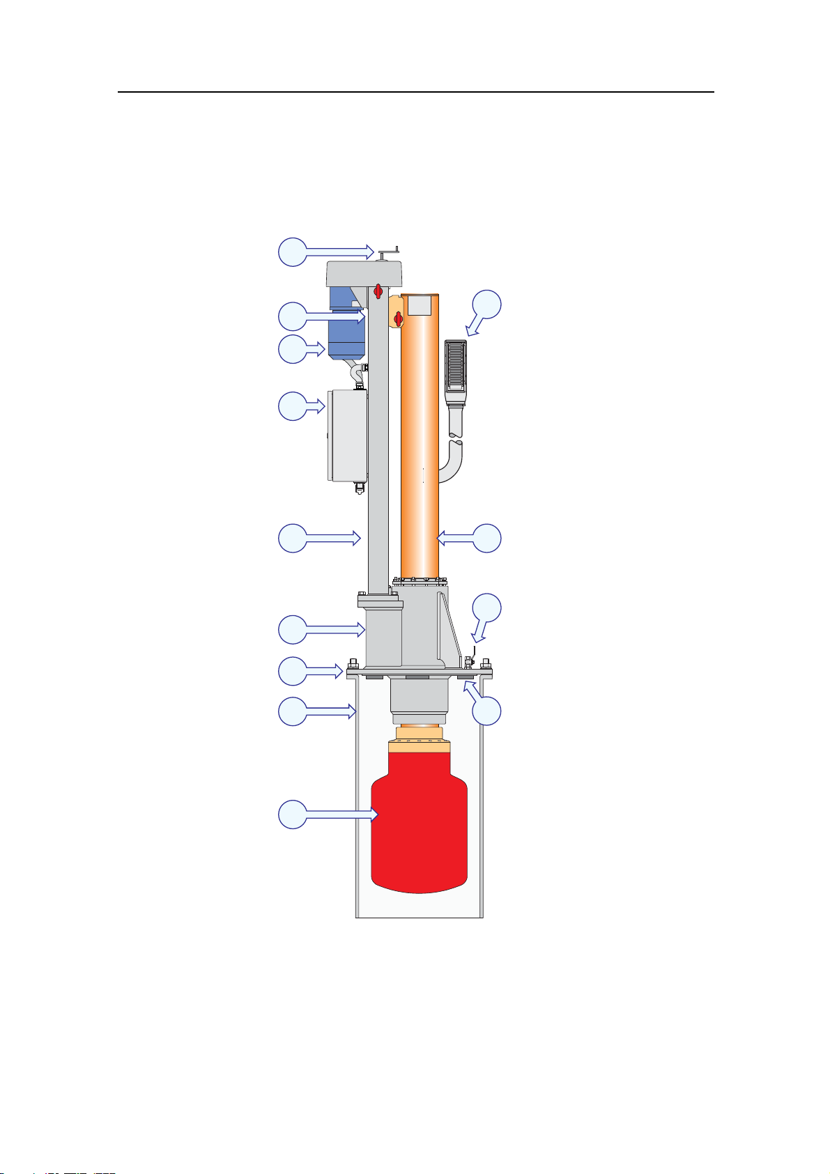
Hull unit familiarization
Figure 1 Hull unit familiarization
A
B
C
D
E
F
G
H
J
K
(A) Hand crank
L
(B) Identification label
(C) Hoisting motor
(D) Motor Control Unit
(E) Hoisting unit
M
(F) Transducer shaft sleeve
10
(G) Mounting flange
(H) Mounting trunk
(I) Transducer
I
(J) Transducer cable
(K) Transducer shaft
(L) Air bleeding cock
(CD015414-003)
(M) Zinc anodes
319568/B

Hull unit main parts
The hull unit is l ocated in the sonar room, close to the transceiver.
It is mounted on a mounting trunk, which accommodates the
transducer when the sonar is switched off. As the transducer
shaft penetrates the ship’s hull, it is required that all personnel
handling installation and service are familiar with the hull unit’s
main parts and operational principles.
Simrad SX95 Hull Unit
A The
hand crank is used for manual hoisting and lowering
of the transducer shaft. When not in use, the hand crank is
stored inside the Motor Control Unit.
B The
identification label provides the hull unit’s name, as well
as its registration- and serial numbers.
C The
hoisting motor is used to lower and hoist the transducer
shaft. In order to rotate in both directions, the motor is
powered by a 3-phase voltage. The motor is controlled by
the Motor Control Unit.
D The
Motor Control Unit controls the hoisting motor. It also
contains the sensor required for sonar beam stabilization.
E The
hoisting unit performs the hoisting and lowering of the
transducer by converting the rotary motion from the motor
to a vertical linear motion for the transducer shaft.
F The
transducer shaft sleeve supports the transducer shaft
and ensures that the assembly is water tight. The area
between the upper and lower bearings is also used as a
grease reservoir for the lubrication of the bearings and for
additional water tightening.
G The
mounting flange provides mechanical fastening of the
hull unit to the mounting trunk. A gasket is used to make the
assembly watertight.
319568/B
H The
mounting trunk accommodates the transducer when the
transducer is retracted.
Note
The trunk is not included in the standard delivery of the
sonar, but can be ordered as an option.
I The transducer has a cylindrical shape. It contains 256
separate wide-band transducer elements.
J The
transducer cable contains two wires for each transducer
element. All are housed in a flexible hose which ends up in
a plug unit for connection to the Transceiver Unit.
K The
transducer shaft penetrates the shaft sleeve, and allows
the transducer to be lowered and hoisted. The transducer is
connected to the lower end of the transducer shaft using a
special plug.
11
Simrad SX95
L The air bleeding cock is provided to avoid air inside the trunk.
We recommend that a pipe is connected to this cock with
continuous rise to the main deck or through the vessel side.
M A number of
zinc anodes are mounted below the mounting
flange to prevent corrosion on the transducer shaft.
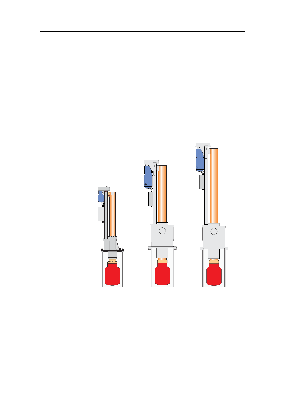
Hull unit models overview
The Simrad SX90 sonar may be delivered with any one of several
different hull unit models.
Figure 2 SX90 Hull unit models
(CD015401-001)
12
SX90
SX92SX95
SX91
SX93
• SX90: This hull unit has 1.2 m stroke length, and it is designed
for maximum speed 24 knots. It will fit on a standard Simrad
trunk with 620 mm pitch centre diameter (PCD).
• SX91: This hull unit has 1.6 m stroke length, and it is designed
for maximum speed 20 knots. It will fit on a standard Simrad
trunk with 620 mm pitch centre diameter (PCD).
• SX92: This is the "standard" hull unit for the SX90 sonar. It
has 1.2 m stroke length, and it is designed for maximum speed
24 knots. It will fit on a standard Simrad trunk with 680 mm
pitch centre diameter.
319568/B

• SX93: This hull unit has 1.6 m stroke length, and it is designed
for maximum speed 20 knots. It will fit on a standard Simrad
trunk with 680 mm pitch centre diameter.
• SX95: This hull unit has 1.0 m stroke length, and it is designed
for maximum speed 12 knots. It will fit on a standard Simrad
trunk with 540 mm pitch centre diameter.
Technical specifications
This section provides the basic technical specifications for the
Simrad SX95 Hull Unit.
Note
We are engaged in continuous development of our products and
reserves the right to alter specifications without prior notice.
Simrad SX95 Hull Unit
Power specifications
• Voltage:
– Nominal: 230 / 380 / 440 Vac, 3-phase (selectable)
– Deviation, 230 Vac: 15 % of nominal voltage
– Deviation, 380/440 Vac: 340 to 485 Vac
– Tra n sient: 20 % of nominal voltage, recover time 3 s
• Power consumption: 1100 VA
• Frequency:47to63Hz
Weights and dimensions, hull unit
• Weight: Approximately 500 kg
• Dimensions:
– SX95 Hull unit outline dimensions on page 55
Weights and dimensions, mounting trunk
• Weight: Approximately 68 kg
• Height: 990 mm
• Flange diameter: 580 mm
• Trunk diameter: 508 mm
• Drawing:
– SX95 Mounting trunk outline dimensions on page 56
– SX95 Mounting trunk production on page 57
– Blind cover for sonar trunk on page 58
319568/B 13

Simrad SX95
Environmental specifications
• Operational temperature: 0 to +40°C
• Storage temperature: -40 to +70°C
• Humidity: 5 to 95% non-condensing
14
319568/B

INSTALLATION PLANNING
Note
For installation in a previously installed trunk system, first read
the information about sonar room requirements. Then proceed
to the Hull Unit installation description.
This chapter provides the marine engineers responsible the
information necessary to plan and install the sonar’s hull unit
according to Simrad’s requirements. Correct installation of the
sonar transducer is vital to the system’s performance. Several
variables must be taken into consideration, the most important
of which is the vessel’s construction. This guide is for use in
selecting the best location for the transducer and includes a brief
description of areas to be avoided.
Note
Installation planning
All installation drawings must be supplied by the shipyard. The
installation must beapproved by the vessel’s national registry and
corresponding maritime authority and/or classification society.
The shipowner and shipyard performing the installation are
responsible for obtaining and paying for installation approval.
Simrad offers free advice for installation planning. Proposed
arrangements may be sent for commentary or suggestions
supplied by Simrad. The following drawings should be submitted
should assistance be requested:
• General arrangement
• Body plan and drawings of relevant bottom tanks and
cofferdams
• Lines plan
Topics
• Location of the hull unit on page 16
• Sonar room requirements on page 17
• Sonar room arrangement example on page 20
319568/B 15

Simrad SX95
Location of the hull unit
Fore and aft
The hull unit should preferably be located within 1/3 to 1/10
of the vessel’s Length Between Perpendiculars (LBP) from its
Forward Perpendicular (FP). Deviations should not be made
without consulting Simrad.
Athwartships
The hull unit may be located on the Centre Line (CL) of the
vessel, or alongside its keel. If the installation is offset from the
vessel’s centre line, make sure that transducer transmission and
reception will not be obstructed by the keel.
Figure 3 Location of the hull unit
16
A Water level at normal trim
B Welding marks to indicate hull unit location when docking
C Length Between Perpendiculars (LBP)
D 1/3to1/10ofLBP
Important considerations related to noise
The installation trunk must be installed so that it will remain
vertical under normal operating c onditions. The primary sources
of underwater disturbance (other than a vessel’s main propeller
and bow/stern thruster) that affect transducer reception are:
319568/B

• Main or bilge keels
• Zinc anodes
• Cooling elements protruding from the hull
• Equipment such as sonar transducers and pilot tubes
• Sea chests
• Overboard discharges
• Dents in the hull
All appendages to the hull, indentations and pipe in/outlets are
potential sources of underwater noise. They may act as resonant
cavities amplifying noise at certain frequencies, create cavitation
or turbulence. Transducers should not be located in the vicinity
of such objects and especially not immediately aft of them.
Sonar room requirements
Installation planning
It is strongly recommended to use a dedicated compartment to
house the hull unit and sonar transceiver unit. These two units
must also be installed relatively close to each other due to the
limited length of the transducer cables. Observe these minimum
sonar room requirements to obtain suitable working conditions
for sonar installation, use and maintenance.
Sonar room physical properties
The following physical properties must be taken into
consideration when the sonar room is planned:
•Size
• Access hatches
•Lifting
•Deck
Size
The sonar room must be dimensioned to house both the hull
unit and the transceiver unit. This is due to the limited length
of the flexible hose protected cabling (approximately 3.5 m)
connecting these two units. A well designed sonar room reduces
the risk of corrosion and simplifies maintenance increasing
system reliability. The sonar room should not be unnecessarily
obstructed by girders, pipes etc. which might cause installation
problems or impede maintenance.
Access hatches
The sonar room must be accessible under all conditions at sea or
at a berth. All doors or hatches should be designed so that the
equipment can be removed without being disassembled.
319568/B 17

Simrad SX95
Lifting device
An attachment point, rated at a minimum of two -2- tons, for
supporting a lifting device should be located above the hull unit.
This permanently installed fixture will facilitate installation
trunk and hull unit mounting, and also may be used for future
equipment maintenance or replacement.
Deck
Once the installation has been completed, the sonar room should
be suitably decked without restricting access to the equipment.
Sonar room environmental requirements
The following environmental properties must be taken into
consideration when the sonar room is planned:
•Heating
• Insulation
• Ventilation
Heating
The sonar room should be equipped with heater, dimensioned to
maintain the equipment within its environmental tolerances (at
least 1000 W), installed close to the deck. Heating is also an
effective method for reducing humidity.
Insulation
Bulkheads must be insulated and provided with an interior wall
to the deck. The insulation should be the minimum equivalent
of 50 mm of rock-wool. In addition, piping passing through the
space prone to condensation must be insulated.
Ventilation
The sonar room should be connected to the vessel’s ventilation
system. If this is not possible, two 3-inch vents must be provided
from the sonar room to the main deck. In the sonar room, the air
inlet should be located in close to the deck and the outlet as high
as possible. A funnel shaped drip-collector should be mounted
below the vent pipes to divert moisture to the bilge.
18
On the main deck, the best ventilation is provided when the outlet
pipe is at least four meters higher than the inlet pipe. To keep out
sea water, rain and spray, the ventilation pipes should be fitted
with goosenecks of the equivalent.
319568/B

Installation planning
Sonar room electrical requirements
The following electrical requirements must be taken into
consideration when the sonar room is planned:
• Conduit
• Bilge pump
• Lights
Conduit
If the cable between the wheelhouse and the sonar room passes
through hatches or areas where it may be damaged, it should be
run through a conduit (two inch conduit is recommended).
Bilge pump
The sonar room should be connected to the vessel’s bilge pump
system. If this is not possible, a separate bilge pump for the sonar
room must be installed.
Lights
The sonar room should be equipped with suitable lighting to
simplify the installation and aid future maintenance.
Sonar room special requirements
The following special requirements must be taken into
consideration when the sonar room is planned:
• Air vent pipe
• Precautions for dry docking
Air vent pipe
An air vent conduit with a minimum of 10 mm internal diameter
must be attached to the air bleeding cock on the hull unit. The
pipe should be laid with continuous rise to free air on deck or
through the ship’s side.
Note
Through-hull modifications are subject to approval by the vessel’s
national registry and corresponding maritime authority. The
shipowner and shipyard are responsible for obtaining installation
approval.
Precautions f or dry docking
Make sure that ample space is provided between the vessel and
dry dock for system installation.
To facilitate future dry docking, mark the position of the installed
trunk on the ship drawings as well as on the hull.
319568/B 19
Simrad SX95
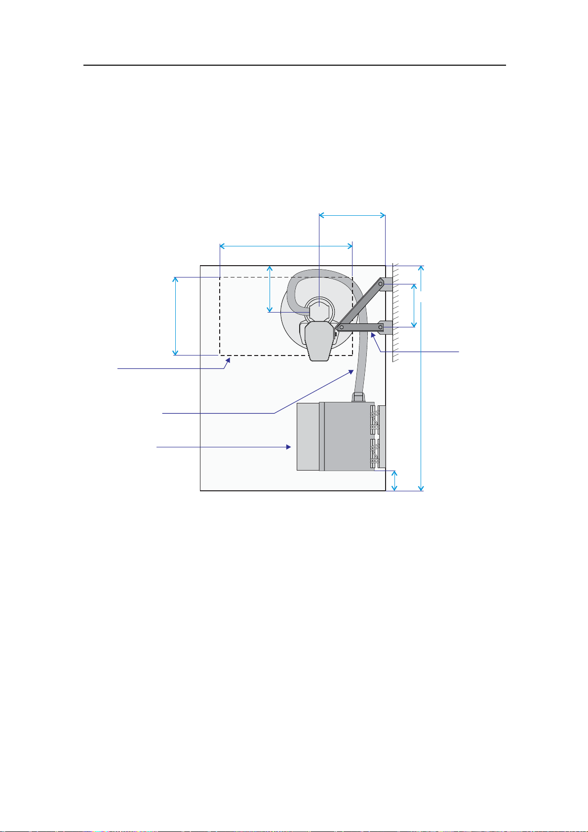
Sonar room arrangement example
These drawings illustrate a typical sonar room with ample space
for hull unit, transceiver unit and personnel.
Figure 4 Sonar room arrangement example, top view
500 mm (*)
1000 mm (*)
600 mm (*)
Hatch
(Minimum size
550 x 1000 mm)
Transducer cable
(Total length 3.5 m)
Transceiver Unit
(CD015417-002)
400 mm (*)
(*) = Recommended minimum
300 mm (*)
Removable
supports
brackets
Maximum
1000 mm
150 mm (*)
20 319568/B
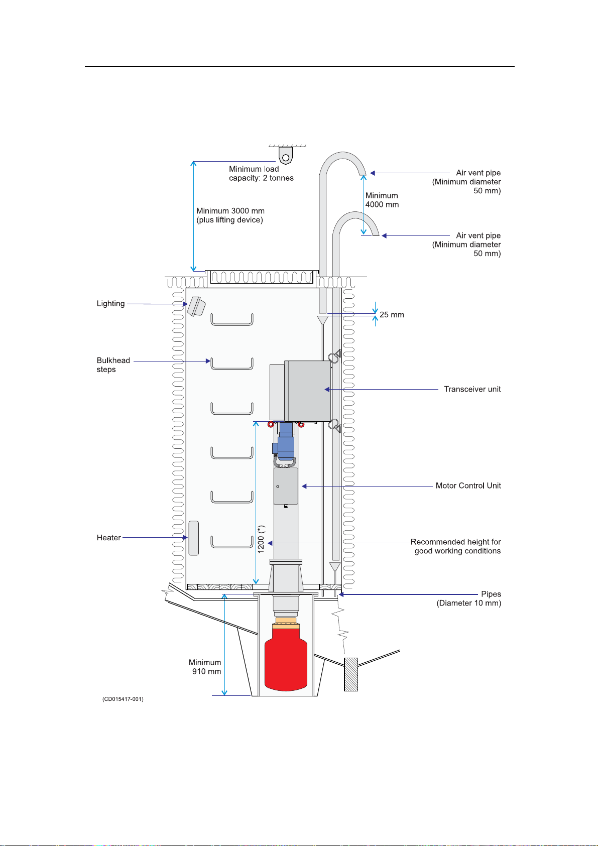
Figure 5 Sonar room arrangement example, side view
Installation planning
319568/B
21

Simrad SX95
SONAR TRUNK INSTALLATION
The sonar trunk provides the physical foundation for the entire
hull unit g antry. The trunk further penetrates the hull, and it is
therefore a crucial part of the hull unit assembly. In order to
ensure proper sonar operation, the location of the sonar trunk
must be carefully selected.
A trunk with a blind cover – approved by Det norske Veritas
(DnV) – can be ordered from Simrad as an optional delivery, or it
may be manufactured by the installation shipyard based on the
drawings in this manual and the properties of the hull.
Note
The installation shipyard must provide all necessary installation
drawings, and if required, these must be approved by the
applicable authorities.
Topics
• Mounting the sonar trunk on page 23
• Sonar trunk protection on page 24
• Sonar trunk installation principles on page 24
• Sonar trunk installation measurements on page 27
Hull unit installation drawings
• SX95 Hull unit outline dimensions on page 55
• SX95 Mounting trunk outline dimensions on page 56
• Blind cover for sonar trunk on page 58
• SX95 Mounting t runk production on page 57
22
319568/B
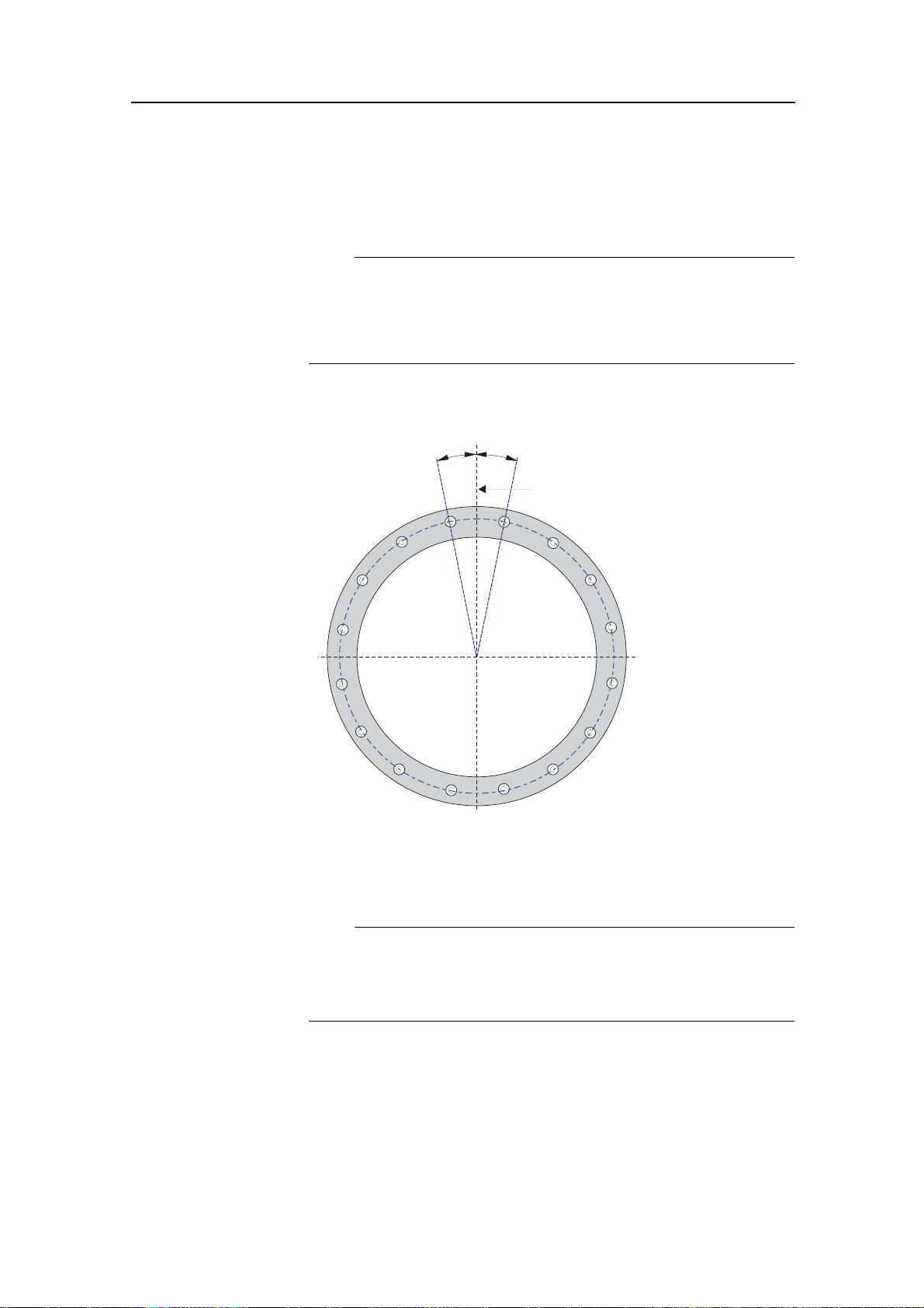
Mounting the sonar trunk
The location of the sonar trunk must be carefully selected.
Note
Note the orientation of the centre line of the trunk with regard to
the mounting bolts.
Remove the gasket on the top flange during welding.
Figure 6 Orientation of the sonar trunk
µ
Sonar trunk installation
µ± °1
Parallel to
centre line
(CD015415-003)
The height from the top of the trunk flange to the underside of
the protection blister must be selected as shown in the referenced
figures.
Note
In order to obtain optimal sonar performance, the total height
of the trunk must be as close as possible to its stated minimum
height.
The top flange must be parallel to the construction waterline in
both the fore-and-aft and athwartship directions.
The installation trunk must be welded to a doubling plate which
must be at least 1.5 times as thick as the surrounding shell plating.
The doubling plate’s final dimensions are to be governed by the
319568/B 23

Simrad SX95
approved installation drawings supplied by the shipyard. The
trunk must also be stiffened by welding knee-plates to it and the
doubling plate in both the fore-and-aft and athwartship directions.
Sonar trunk protection
Protecting the blister
A steel blister must be fitted for protection. The blister shown
is welded to the shell plating and then filled with oil to prevent
corrosion. This method provides excellent protection and
simplifies maintenance.
Corrosion protection
As soon as all installation, welding and grinding has been
performed, the trunk and the surrounding area should be primed
and painted using a quality protective coating.
Sonar trunk installation principles
Observe the next two drawings, these illustrate the i nstallation
of the sonar trunk.
24
319568/B
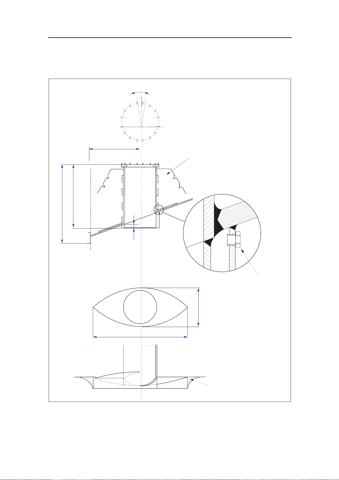
Figure 7 Installation of a trunk with open blister
Fore-and-aft view
A
Sonar trunk installation
A:
As short as possible
B:
Max. 35 7/8" (910 mm)
C:
Min. 1 9/16" (40 mm)
D:
Min. 35 7/8" (910 mm)
E:
Min. 22" (560 mm)
3-4 knee-plates, must be
welded to frames or floors
D
B
Bottom view
Side view
2.5-3xE
C
Plug for filling of oil
Thickness of plates
E
Knee-plates: 3/8" (10 mm)
Blister and deflection
bracket: 1/4" (6 mm)
The circular opening of the
blister should have a
diameter equal to the inside
diameter of the trunk.
Deflection-brackets should
be welded only to the
shell-plating.
(CD015415-004)
319568/B 25

Simrad SX95
Figure 8 Installation of a trunk with oil filled blister
Fore-and-aft view
A
3-4 knee-plates, must be
A:
As short as possible
B:
Max. 35 7/8" (910 mm)
C:
Min. 1 9/16" (40 mm)
D:
Min. 35 7/8" (910 mm)
E:
Min. 22" (560 mm)
welded to frames or floors
D
B
Bottom view
Side view
2.5 - 3xE
C
Thickness of plates
E
Knee-plates: 3/8" (10 mm)
Blister and deflection
bracket: 1/4" (6 mm)
The circular opening of the
blister should have a
diameter equal to the inside
diameter of the trunk.
Deflection-brackets must
only be welded to the
(CD015415-005)
shell-plating.
26 319568/B

Sonar trunk installation
Sonar trunk installation measurements
For future reference, the measurements “A”, “B”, “C” and “D”
from the drawing must be made and noted in the table below.
Table 1 Trunk installation measurements
Millimeters Inches
“A”
“B”
“C”
“D”
319568/B 27

Simrad SX95
HULL UNIT INSTALLATION
This chapter describes the physical installation of the Simrad
SX95 Hull Unit.
The hull unit is a crucial part of the sonar system. Due to its
physical size and weight, and the fact that the trunk penetrates
the vessel hull, it is very important that the hull unit is installed
and secured properly.
Note
The installation shipyard must provide all necessary installation
drawings, and if required, these must be approved by the
applicable authorities.
Topics
• How to unpack the hull unit from its transport box on page 29
• Hull unit mounting on page 30
• Bleeding air cock on page 31
• Mechanical support on page 32
• Transducer alignment on page 32
• Hull unit installation check list on page 33
Related topics
• Hull unit familiarization on page 10
Hull unit installation drawings
• SX95 Hull unit outline dimensions on page 55
• SX95 Mounting trunk outline dimensions on page 56
• Blind cover for sonar trunk on page 58
• SX95 Mounting t runk production on page 57
28
319568/B

Hull unit installation
How to unpack the hull unit from its transport box
Note
The transducer is protected to prevent damage during transport
and hull unit installation. This protection must remain attached
while the hull unit is being manoeuvred into the sonar room.
Figure 9 Removing the hull unit from its transport box
A
BB
C
A Lifting eye on the hoisting unit
B Mounting hardware (wooden cradle and support
construction)
C Transducer protection
1 Remove the top cover of the wooden box.
2 To remove the fastening hardware (G), pull out the
marked with Indian ink.
3 If you wish to re-use the box to hold the old h
sure that you keep all the fastening hardw
ull unit, make
are used to secure
the hull unit in the wooden box.
(CD015414-004)
nails
4 Fasten the lifting tackle to the two lift
on the top of the hoisting unit and lift
the transducer protection in place)
ing eye bolts (A)
the hull unit (with
carefully out of the
transportation box.
Note
Do not remove the transducer protection (H)fromthe
transducer until just before the hull unit is lowered onto the
mounting trunk.
319568/B 29

Simrad SX95
Figure 10 Use the correct lifting eye!
There are two lifting
eyes on each side of
the hull unit: one
on the hoisting unit
and one on the top of
the transducer shaft.
Make sure that you use
the lifting eye on the
A
hoisting unit (A)when
you lift the hull unit out
of the transportation
box!
(CD015412C)
5 Ensure that you keep the transducer cable and connector dry.
Watch these carefully to prevent them from being damaged,
stuck or hooked on to protruding objects while manoeuvring
the hull unit into the sonar room.
Hull unit mounting
Figure 11 Orientation of the hull unit
Bow
The hull unit should normally be
oriented with the hoisting/lowering
motor pointing aft. If this orientation
makes the Motor Control Unit attached
to the hull unit difficult to access, the
hull unit may be oriented in the most
suitable position.
Note
The Motor Control Unit must never be
physically disconnected from the Hull
Unit.
(CD015400D)
30 319568/B

Hull unit installation
Hull unit mounting procedure
Observe the following procedure. To ensure correct operation,
tick off every item when the action has been carried out.
1
protection in place) into the sonar room
2
the gasket is not damaged.
3
future use.
4
unit carefully onto the trunk.
5
140 Nm.
6
handle them with great care to prevent mechanical damage.
Bleeding air cock
Figure 12 Bleeding air cock
A
Use a tackle to lower the hull unit (with the transducer
Remove the blind cover from the trunk and check that
Store the blind cover in the sonar room for possible
Remove the transducer protection and lower the hull
Tighten the flange nuts with a torque of approximately
Keep the transducer cable and connector dry, and
To avoid damage to the transducer by the transmission
in air inside the trunk, a pipe with a minimum inside
diameter of 10 mm must be attached to the air bleeding
cock. This vent should be run with continuous rise to the
main deck or through the vessel’s side. Make sure the
air bleeding cock is opened.
(CD015401C)
B
C
(A) Minimum 10 mm internal diameter
(B) 3/8” pipe thread
(C) Valve shown in opened position
319568/B 31

Simrad SX95
Mechanical support
Note
To ensure the safety of the sonar system and the vessel, it is very
important that the mechanical support of the hull unit gantry
is satisfactory.
To prevent unwanted vortex induced vibration, the hull unit
must be secured to the bulkhead. Use the two pre-drilled holes
on the gantry to mount support brackets in the fore-and-aft and
sideways direction. It must be possible to remove the support
brackets if maintenance is required.
Transducer alignment
Even though you may have installed the hull unit oriented
differently than shown in this chapter, the transducer shall n
be mechanically aligned.
ot
Transducer alignment is performed in the SX90 Processor Unit
by rotating the echo presentation on the display. This is described
in section Alignment and offset adjustments on page 51.
32
319568/B

Hull unit installation check list
Perform a close visual inspection of the sonar room and the
physical installation of the hull unit. Refer to the sonar room
requirements, and fill in the table below.
Table 2 Hull unit installation check list
Hull unit installation
Item
Are the access hatches satisfact ory?
Is the heating satisfactory?
Is the insulation satisfactory?
Is the ventilation satisfactory?
Is the air vent pipe satisfactory?
Is a bilge pump installed?
Is the room lighting satisfactory?
Is the sonar room suitably decked?
Is the mechanical support of the hull unit
satisfactory?
Do you have satisfactory access to the Motor
Control Unit?
YES NO
If the answer to any of these questions is NO, note the deficiencies
in the Installation remarks and signature.
Related topics
• Sonar room requirements on page 17
319568/B 33

Simrad SX95
CABLE LAYOUT AND INSTALLATION
This chapter describes the installation requirements for Simrad
SX95 hull unit cables. These instructions must be used together
with the applicable cable plan.
Note
All electronic installations and corresponding wiring must be in
accordance with the vessel’s national registry and corresponding
maritime authority and/or classification society.
If no such guidelines exist, we recommend that Det Norske
Veritas (DNV) Report No. 80-P008 «Guidelines for Installation
and Proposal for Test of Equipment» be used as a guide.
Topics
• Cable plan on page 35
• Cabling principles on page 36
• Cable procedures on page 37
Related topics
• Detailed list of cables on page 59
• Cable specifications on page 60
• Cable connections on page 63
• Basic cable requirements on page 66
34
319568/B

Cable plan
The list below shows the cables used by the SX95 Hull Unit.
Figure 13 Simrad SX95 Hull Unit cable plan
(CD015503B)
Cable layout and installation
SX90/C31
K
SX90/C04*
SX90/C17
(Vac)
SX90/C06 (3-phase Vac)
SX90/C05*
List of units
(G) = Transceiver Unit
(H) = Hull Unit
(I) = Motor Control Unit
G
SX90/C32*
SX90/C35*
H
I
List of cables
SX90/C06: AC Mains to Hull Unit
SX90/C32: Ethernet control
SX90/C35: Transducer cable
319568/B 35

Simrad SX95
Cabling principles
This chapter provides generic information about the cabling
principles.
Cable identifications
On the cable layout drawing and in the corresponding cable
list(s), all cables are identified with individual cable numbers.
Unless otherwise defined, each cable is identified with a Cxx
number, where xx is an integer. References are made to dedicated
cable drawings. If required, the shipyard or owner may also
identify the cables according to their own system. Unless
otherwise specified, this document will however only refer to the
identification numbers provided by Simrad.
Cable parameters
A drawing with additional parameter specifications for each c able
is provided. Each cable drawing may, when applicable, include:
• Required minimum specifications
• Connections at each end (including reference to the
corresponding: system unit, terminal board identification and
plug/socket to be used)
• Corresponding terminations
• Number of cores
System and shipyard cables
Cables fall into two categories.
• System cables: These cables are supplied by Simrad.
• Shipyard cables: These cables must be provided by the
shipyard performing the installation, or the shipowner.
Note
Simrad accepts no responsibility for damage to the system or
reduced operational performance caused by improper wiring.
36 319568/B

Cable procedures
Observe the following procedure to perform the sonar cabling.
Note that detailed information about cable specifications,
termination and connectors are provided in the referenced
sections. To ensure correct operation, tick off every item when
the action has been carried out. All cables are provided by
Simrad unless otherwise specified.
Note
Before you perform the sonar cabling, ensure that the mains
circuit breaker for the sonar system is switched off.
In order to provide for maintenance and to allow for vibration,
make sure that some slack is inserted on all cables.
Note
Cable layout and installation
DO NOT mount the flexible transducer cable to the Transceiver
Unit. This will be described later.
Topics
• AC mains to Motor Control Unit (C06) on page 38
• Transceiver Unit to Motor Control Unit (C32) on page 39
• Transducer cable (C35) on page 40
Related topics
• Transceiver Unit connections on page 65
• Motor Control Unit connections on page 64
319568/B 37

Simrad SX95
AC mains to Motor Control Unit (C06)
1 Connect the 3–phase AC mains cable C06 from the
Figure 14 C06 connections
Motor Control Unit to the vessel’s AC mains.
Note
This cable must be provided by the installation shipyard.
Use 4 x 2.5 mm² cable, ensure that the screen is properly
terminated in the cable gland.
DO NOT apply 3–phase power to the Motor Control Unit
until instructed by the applicable start-up procedure.
For additional details, see SX90/C06 AC mains to Motor
Control Unit on page 59 and AC mains cable to Motor
Control Unit on page 61.
38 319568/B

Cable layout and installation
Transceiver Unit to Motor Control Unit (C32)
If the Transceiver Unit has been installed, make the following
connection:
1
2
Figure 15 C32 connections
Locate the 8 meters terminated C32 patch cable
provided with the transceiver.
Connect the ethernet cable C32 from the left ethernet
socket under the Transceiver Unit to the ethernet socket on
the Motor Control Unit.
319568/B 39

Simrad SX95
Transducer cable (C35)
The transducer cable (C35) is provided by Simrad. It is physically
connected to the top of the transducer shaft, and terminated in the
other end with a large connector.
Note
Do not mount the flexible transducer cable to the Transceiver
Unit. This operation is described in the Simrad SX90 Installation
manual.
40 319568/B

START-UP PROCEDURES
The procedures in this chapter shall be carried out once all the
hardware units have been installed, and the cabling is finished.
Note
When you carry out these procedures, make sure that you only
perform those tasks described, and in the given order.
Check off every item in the procedure as you carry on.
Topics
• Starting up the Hull Unit on page 41
• Alignment and offset adjustments on page 51
Starting up the Hull Unit
Start-up procedures
Observe the following procedure to start up the Hull Unit. To
ensure correct performance, tick off every item when the action
has been carried out.
WARNING
Beforeyoustartupthesonarequipmentona
recently launched vessel, make sure that the depth
under the keel is sufficient for the transducer to
be lowered safely.
When you start up the equipment on board a
vessel in dry dock, check first under the vessel
and inside the sonar room. Personnel, tools and
other potential obstructions must be kept clear of
thetransducerandrelatedloweringandhoisting
machinery to avoid personal injury or damage to
the equipment.
Topics
• Hull unit familiarization on page 42
• Motor Control Unit familiarization on page 43
• Functional check on page 44
319568/B
• Apply 3-phase AC power on page 45
• Check hoist motor’s 3–phase AC connections on page 46
• Check the 3–phase connection for correct rotation direction
on page 47
• Check the contactor operation on page 48
• Functional check with hoist and lower operations on page 49
41

Simrad SX95
Hull unit familiarization
Figure 16 Hull unit familiarization
A
B
C
D
E
F
G
H
J
K
(A) Hand crank
L
(B) Identification label
(C) Hoisting motor
(D) Motor Control Unit
(E) Hoisting unit
M
(F) Transducer shaft sleeve
42
(G) Mounting flange
(H) Mounting trunk
(I) Transducer
I
(J) Transducer cable
(K) Transducer shaft
(L) Air bleeding cock
(CD015414-003)
(M) Zinc anodes
319568/B

Motor Control Unit familiarization
Figure 17 Motor Control Unit familiarization
Start-up procedures
(A) Internal 24 Vdc power supply
HOIST STOP
REMOTE LOWER
S302 P302
S303
S301
E301
K303
L1
K302K301
L2
A
F301
(CD015409B)
B
(B) Ethernet connector
(F301) Fuse for internal power
supply
(E301) Terminal strip for AC
mains input
(K301) Hoisting contactor
(K302) Lowering contactor
(K303) Phase watch relay
(L1) Yellow indicator light
(L2) Green indicator light
(S301) Motor protecting switch
(S302) Hoist/lower selector
(S303) Hand crank with safety
switch
(P302) Connector for hull unit
limit switches and rotation sensor
During normal operational conditions, the two following
indicator lamps shall be lit:
• Indicator lamp
L1 indicates that the phase watch relay K303
is activated. This mean that the 3-phase voltage is applied
to the hoist/lower system, and that the three phases are
correctly connected with regard to the training direction of
the hoist/lower motor.
• Indicator lamp
L2 indicates that the internal +24 Vdc power
supply for the control electronic is operational.
319568/B 43

Simrad SX95
Functional check
Before you commence with the start-up procedure, check the
following items. To ensure correct operation, tick off every item
when the task has been carried out.
1
Check that the 3-phase mains fuses are disconnected
in the ship’s fuse box.
2
Use a spanner to open the door on the Motor Control
Unit which is mounted on the Hull Unit gantry.
3
Locate the motor protecting switch S301,andcheck
that the operating handle is pressed down to OFF position.
4
Check that t he hoist/lower switch S302 in the Motor
Control Unit is set in the STOP position.
44
319568/B

Start-up procedures
Apply 3-phase AC power
Observe the following procedure to apply 3-phase mains power
to the hull unit.
1
Locate the motor protecting switch S301 in the Motor
Control Unit, and check that the operating handle is pressed
down to OFF position.
2
Check that t he hoist/lower switch S302 in the Motor
Control Unit is set in the STOP position.
3
Re-insert the 3-phase mains fuses for the hull unit in
the ship’s fuse box.
4
Measure the three-phase voltage on the terminals E301
in the Motor Control Unit.
• Write down the measured voltage here:
Supply voltage:
5 Adjust the release current on the motor protecting
switch
S301 according to the three-phase voltage:
• 230 Vac: 5,5 A
• 380/440 Vac: 4 A (minimum)
Figure 18 Motor Control Unit with S301 and E301
S302
S301
E301
(CD015409K)
HOIST STOP
REMOTE LOWER
319568/B 45

Simrad SX95
Check hoist motor’s 3–phase AC connections
In order to ensure that the hoisting motor operates properly, and
to avoid serious damage to the motor, you must check that the
motor connections are made in accordance with the supplied
3–phase voltage.
1
Remove the 3-phase mains fuses for the hull unit in
the vessel’s fuse box.
2
Remove the cover for the mains connection on the
motor.
3
Refer to the illustration, and check if the motor
connections are made in accordance with the supplied
3–phase voltage.
Figure 19 Mains connection to the motor
230 Vac
380/440 Vac
46
(CD015407A)
Note
The order of the connection wires must not be changed!
4 If the connections do not match the 3–phase voltage,
rewire to make them correspond to the m easured voltage.
5
Re-insert the 3-phase mains fuses for the hull unit in
the vessel’s fuse box.
319568/B

Start-up procedures
Check the 3–phase connection f or correct rotation direction
The Motor Control Unit is equipped with a Phase Watch Relay
(
K303), which prevents operation of the hoist/lower motor if
the 3-phase connections are wrong with respect to the motor’s
rotation direction.
Figure 20 Motor Control Unit with S302, S301, E301, K303
and LED L1
HOIST STOP
S302
REMOTE LOWER
S301
E301
(CD015409L)
K303
L1
1 Check that t he hoist/lower switch S302 in the Motor
Control Unit is set in the STOP position.
S301 by
2
Switch on the motor protecting swi
pressing the operating handl
3
4
Check that the LED L1 on the front of the Phase
Watch Relay (
K303)islit.
If the LED is not lit, observe the following procedure:
e upwards to ON position.
tch
1 Disconnect the ship’s 3-phase fuses.
2 Change two of the 3-phase connections on the terminal
E301 in the Motor Control Unit.
3 Re-insert the 3-phase fuses in the ship’s fuse box.
4 Check again that the LED on the front of the Phase
Watch Relay (
5
Switch off the motor p
pressing the operat
319568/B 47
K303)islit.
rotecting switch
S301 by
ing handle downwards to OFF position.

Simrad SX95
Check the contactor operation
Normally, in this part of the test procedure, the transducer shaft
will be in upper position with the upper limit switch activated.
This operational test of the hoist/lower contactors will not require
the 3-phase power to be applied to the motor.
Figure 21 Motor Control Unit with S301, S302, K301, K302 and L2
1 Locate the motor protecting switch S301,andcheck
that the operating handle is pressed down to OFF position.
2
Check that the LED indicator L2 on the front of the
24 Vdc power supply is lit.
3
Set the hoist/lower switch S302 to HOIST position,
and check that the hoisting contactor
K301 is not activated.
• If the contactor was activated, press the upper limit switch
S304 upwards, and check that the contactor is deactivated.
4
5
Set the hoist/lower switch S302 to the LOWER position
and check that the lowering contactor
K302 is activated.
Press the lower limit switch S305 downwards, and
check that the contactor is deactivated while activating the
switch.
6
7
Locate the hand crank inside the Motor Control Unit.
Remove the hand crank from its storage position, and
check that the contactor is deactivated. D
o not place the
hand crank back into its storage position.
8
Set the hoist/lower switch S302 to the STOP position.
48 319568/B

Start-up procedures
Functional check with hoist and lower operations
The hull unit is now all powered up, and the final functional test
can take place.
1
Verify that the hand crank is removed from its storage
position in the Motor Control Unit.
2
Switch on the motor protecting switch S301 by
pressing the operating handle upwards to ON position.
3
Set the hoist/lower switch S302 to the LOWER
position.
Figure 22 Motor Control Unit with S301, S302 and S303
HOIST STOP
REMOTE LOWER
S302
S303
S301
(CD015409N)
4 Check the training direction of the hoist/lower motor
by very briefly pressing the hand crank safety switch
5
If the transducer shaft was hoisted, perform the
S303.
following procedure:
1 Disconnect the vessel’s 3-phase mains fuses.
2 Change two of the 3-phase connections in the mains
connection box on the motor.
3 Re-insert the 3-phase mains fuses in the vessel’s fuse
box.
4 Check that the transducer shaft is lowered when briefly
pressing the h and crank safety switch
319568/B 49
S303.

Simrad SX95
6 Set the hoist/lower switch S302 to the STOP position.
7
Put the hand crank back to its storage position in the
Motor Control Unit.
8
Check if there is sufficient space under the keel to
lower the transducer.
9
Make sure that the flexible transducer cable is in
such a position that the transducer can be lowered without
stretching or hard-bending the cable.
Note
Watch the cable carefully during the next steps in this
procedure!
10 Set the hoist/lower switch S302 to LOWER position to
lower the transducer all the way down.
• Lowering will be stopped automatically when the top of
the transducer shaft makes contact with the lower limit
switch
S305.
• If necessary, the lowering operation can easily be stopped
in any position by setting the switch
S302 to STOP
position.
11
Set the hoist/lower switch S302 to HOIST position to
hoist the transducer back up.
• Hoisting will be stopped automatically when the top of
the transducer makes contact with the upper limit switch
S304.
• If necessary, the hoisting operation can easily be stopped
in any position by setting the switch
S302 to STOP
position.
12
Repeat the hoist/lower operation to find the best
position for a permanent fastening of the flexible transducer
cable.
13
14
Set the hoist/lower switch S302 to STOP.
Switch off the motor protecting switch S301 by
pressing the operating handle downwards to OFF position.
The hull unit is now ready for further cabling (Ethernet cable to
the transceiver unit for hoist/lower control) and system testing.
The system test is provided in the relevant sonar installation
manual.
50
319568/B

Alignment and offset adjustments
When the system start-up procedure for the complete sonar
system has been performed, you must acquire the alignment
angle of the sonar picture and the stabilisation sensor offset.
These values must be entered into the sonar system.
Alignment of the sonar picture
Independent of the hull unit orientation, the alignment is always
defined as:
• the angle measured clockwise from the bow to the 0 degrees
transducer mark.
The 0 degrees transducer mark is located outermost on the
mounting flange, and it is marked as a red “0”. Depending on
the transducer mounting, it can be located at any angle on the
mounting flange, not necessarily as shown in the illustration
below.
Start-up procedures
Figure 23 Hull unit alignment
This is the alignment angle
o
0 transducer
mark
Bow
0
(CD015400F)
Observe the following procedure to align the sonar picture.
1 Locate the 0° transducer mark.
2 Estimate the approximate alignment angle ( 0 to 360°)
clockwise from the bow to the 0° transducer mark.
• The 22,5° angle between each mounting bolt can be used
as an aid.
3 Turn the echo picture on the display in the following way:
1 Open the
2 Click the
319568/B 51
Setup menu.
Test to open the System test menu.

Simrad SX95
3 Click the Installation Menu button, and observe that the
menu appears on the top of the display.
4 Select
transceiver configuration
Installation →Alignment. Observe that the Sonar
parameter dialogue appears at
the bottom of the menu field.
5 Click the
Alignment button.
6 Enter the estimated alignment angle.
4 Check that the echo picture on the display is correct in
relation to the ambient situation.
• If not, make a fine adjustment of the alignment.
In order to make a correct alignment, a particular target such
as a buoy is required. When the alignment is correct, write the
angle here.
Alignment correction (degrees):
Adjusting the stabilisation sensor offset
Independent of the hull unit orientation, the offset of the
stabilization sensor is always defined as:
• the angle measured clockwise from the 0 degrees transducer
mark to the 0 degrees reference for the stabilization sensor.
The 0 degrees transducer mark is located outermost on the
mounting flange. The 0 degrees reference for the stabilization
sensor is always related to the gantry, as indicated in the figure
below.
Figure 24 Offset angle definition
This is the offset angle
o
0 transducer
mark
0
Bow
o
0 stabilisation
sensor
(CD015400G)
52 319568/B

Start-up procedures
Estimating the offset angle
Observe the following procedure to estimate the offset of the
stabilization sensor.
1 Locate the 0 degrees transducer mark.
2 Estimate the approximate offset angle (0 to 360°) clockwise
from the 0° transducer mark to the 0° reference stabilization
mark.
• The 22,5° angle between each mounting bolt can be used
as an aid.
3 Record the estimated offset angle.
Offset angle(degrees):
Entering the stabilisation offset angle
Observe the following procedure to enter the offset stabilization
angle as a parameter into the sonar system.
1 Open the
2 Click the
3 Click the
Setup menu.
Tes t button to open the System test menu.
Installation Menu button, and observe the menu
that appears on the top of the display.
4 Select
5 Observe that t he
Installation →Installation →Alignment.
Sonar transceiver configuration parameter
dialogue appears at the bottom of the menu field.
6 Click the
Offset button.
7 Enter the estimated offset angle.
319568/B 53

Simrad SX95
DRAWING FILE
This chapter contains relevant drawings related to the electrical
and physical installation of the S X95 Series hull unit.
Note
The mechanical drawings are for information and guidance only.
They are not in scale. All dimensions are in mm unless otherwise
is noted.
The original drawings are available on PDF and/or AutoCad’s
DWG format. See the product CD, or visit w
to download.
Hull unit drawings
• SX95 Hull unit outline dimensions on page 55
ww.simrad.com
• SX95 Mounting trunk outline dimensions on page 56
• Blind cover for sonar trunk on page 58
• SX95 Mounting t runk production on page 57
54
319568/B

SX95 Hull unit outline dimensions
Drawing file
155
[6,102]
1645
[64,764]
874
[34,409]
Lifting
point
Lifting
point
220
[8,660]
990
[38,976]
ø150
[5,906]
382
[15,039]
Note:
All measurements are in mm and [inches].
The drawing is not in scale.
1000
[39,370]
ø483
[19,016]
ø508
[20,000]
ø580
[22,835]
Bow
ø662
[26,063]
CD015414-005 Page 1 of 1
318900 Rev.A
319568/B 55

Simrad SX95
SX95 Mounting trunk outline dimensions
56 319568/B

SX95 Mounting trunk production
Classification society marking
3
-
+
990
Drawing file
45°
10
18
-0
+1
(508)
22.5°
M16
0.5
16 HOLES,SPACING 22.5
+1
-0
ø460
ø540
ø580
2
+
-
(12.5)
O
Note:
All measurements are in mm.
The drawing is not in scale.
319568/B 57
CD15106-003 Page 1 of 1
830-113361 Rev.A

Simrad SX95
Blind cover for sonar trunk
2
0
-
+
13
+
0.5
-
18
0.5
16 holes, spacing 22.5
o
Note:
All measurements are in mm
The drawing is not in scale
ø540
2
+
-
ø580
CD015106-001 Page 1 of 1
830-113362 Rev.A
58 319568/B

APPENDIX A — CABLE DETAILS
This appendix contains specific cable details related to the
Simrad SX95 Hull Unit.
Topics
• Detailed list of cables on page 59
• Cable specifications on page 60
• Cable connections on page 63
Detailed list of cables
The list below specifies each cable used on the Simrad SX95
Hull Unit. References are made to detailed cable drawings and
specifications.
SX90/C06 AC mains to Motor Control Unit
Appendix A Cable details
The AC mains to the Hull Unit is connected to the Motor Control
Unit. This is a special mains cable, and it must be provided by
the installation shipyard.
Note
This cable can be prepared for installation, but it must NOT be
connected to the Motor Control Unit until specifically instructed
by the setup procedure.
Related topics
• Motor Control Unit connections on page 64
• AC mains cable to Motor Control Unit on page 61
SX90/C32 Transceiver to Motor Control ethernet
The Transceiver Unit is connected to the Motor Control Unit by
means of a single Ethernet cable. A suitable cable is provided
by Simrad.
Related topics
• Transceiver Unit connections on page 65
• Motor Control Unit connections on page 64
• Ethernet cable with RJ45, “straight” on page 62
SX90/C35 Transducer cable
The transducer cable is physically connected to the transducer. It
is connected to the side socket of the Transceiver Unit by means
of a special connector.
319568/B 59

Simrad SX95
Cable specifications
The drawings provided specifies in detail each cable used by
the SX95 Hull Unit.
60
319568/B

Appendix A Cable details
HOIST STOP
REMOTE LOWER
AC mains cable to Motor Control Unit
This cable is used to connect 3-phase mains supply and ship’s
ground to the hoist/lower motor on the hull unit. The connections
are made to the Motor Control Unit.
Ground
HOIST
Motor Control Unit
Main
screen
Cable
access
Observe proper
cable grounding!
3-phase
230/380/440 Vac mains
W323
Rev.B
Caution
Observe the difference between 230 Vac and 380/440
Vac wiring on the hoist motor!
• Conductors: 4 x 2.5 mm²
• Screen: Overall braided
• Voltage: 750 V
• Maximum diameter: 17 mm
AC Mains supply, Motor Control Unit
319568/B 61

Simrad SX95
Ethernet cable with RJ45, “straight”
This cable is used to provide standard ethernet connections. Note
that various categories exists. Normally, Cat.5 and Cat.6 cables
are used in local area networks with bandwidth exceeding 100
Mbit
Ethernet cables are available commercially in different lengths,
colours and categories.
Pin 1
RJ45 plug
Tx Data+ Tx Data+
Tx Data- Tx Data-
Rx Data+ Rx Data+
Rx Data- Rx Data-
W403
Rev.B
Pin 8
Pin 1
View
Pin 8
RJ45 plug
11
22
33
44
55
66
77
88
Pairs
Ethernet 10Base-T “Straight Through”
(White/Orange)
(Orange)
(White/Green)
(Blue)
(White/Blue)
(Green)
(White/Brown)
(Brown)
62
In order to prevent noise and crosstalk, you are strongly advised
to use the cable pairs indicated in the drawing.
• Conductors: Defined by the manufacturer
• Screen: Overall screened
• Voltage: Defined by the manufacturer
• Maximum diameter: Defined by the manufacturer
• Termination: RJ45 in each end
319568/B

Cable connections
Care must be taken to ensure that the correct terminations are
used for all cable conductors, especially those that are connected
to terminal blocks. In this case, crimped sleeve-terminations
must be fitted to prevent the conductor core from fraying and
making a bad connection with the terminal block.
Note
Wherever crimped terminals are used, the correct size of crimp
and crimping tool m
Appendix A Cable details
ust be used.
319568/B 63

Simrad SX95
Motor Control Unit connections
The illustration below shows the cable connections used on the
Motor Control Unit.
Figure 25 Motor Control Unit connections
(CD015409C)
HOIST STOP
REMOTE LOWER
Ground
3-phase
230/380/440 Vac mains
A
(A) 3–phase AC Mains power input (SX90/06)
(B) Ethernet connector (SX90/33)
Note
Observe proper grounding of th
cable to Motor Control Unit on
e mains cable. See AC mains
page 61 for details.
B
64 319568/B

Appendix A Cable details
Transceiver Unit connections
The illustration below shows the cable sockets used on the
Transceiver Unit.
Figure 26 Transceiver Unit connections
(A) Ethernet connector for Motor Control unit (SX90/C32)
(B) Ethernet connector for wheelhouse (SX90/C31)
(C) AC Mains power connector (SX90/C05)
319568/B 65

Simrad SX95
APPENDIX B — BASIC CABLE REQUIREMENTS
This chapter provides general information related to the
installation of system cables.
Cable trays
All permanently installed cables associated with the system
must be supported and protected along their entire l engths using
conduits and/or cable trays. The only exception to this rule is
over the final short distance (maximum. 0,5 meters) as the cables
run into the cabinets/units to which they are connected. These
short service loops are to allow the cabinets to move on their
shock mounts, and to allow maintenance and repair.
• Wherever possible, cable trays must be straight, accessible and
placed so as to avoid possible contamination by condensation
and dripping liquids (oil, etc.). They must be installed away
from sources of heat, and must be protected against physical
damage. Suitable shields must be provided where cables are
installed in the vicinity of heat sources.
• Unless it is absolutely unavoidable, cables should not be
installed across the vessel’s expansion joints. If the situation
is unavoidable, a loop of cable having a length proportional
to the possible expansion of the joint must be provided. The
minimum internal radius of the loop must be at least twelve
times the external diameter of the cable.
• Where a service requires duplicate s upply lines, the cables
must follow separate paths through the vessel whenever
possible.
• Signal cables must not be installed in the same cable tray or
conduit as high-power cables.
• Cables containing insulation materials with different
maximum-rated conductor temperatures should not be
bunched together (that is, in a common clip, gland, conduit or
duct). When this is impractical, the cables must be carefully
arranged such that the maximum temperature expected in
any cable in the group is within the specifications of the
lowest-rated cable.
• Cables with protective coverings which may damage other
cables should not be grouped with other cables.
66
• Cables having a copper sheath or braiding must be installed
in such a way that galvanic corrosion by contact with other
metals is prevented.
• To allow for future expansion of the system, all cables should
be allocated spare conductor pairs. Also, space within the
vessel should be set aside for the installation of extra cables.
319568/B

Appendix B Basic cable requirements
Radio Frequency interference
All cables that are to be permanently installed within 9 m (30
ft) of any source of Radio Frequency (RF) interference such as
a transmitter aerial system or radio transmitters, must, unless
shielded by a metal deck or bulkhead, be adequately screened by
sheathing, braiding or other suitable material. In such a situation
flexible cables should be screened wherever possible.
It is important that cables, other than those supplying services to
the equipment installed in a radio room, are not installed through
a radio room, high power switch gear or other potential sources
of interference. Cables which must pass through a radio room
must be screened by a continuous metal conduit or trunking
which must be bonded to the screening of the radio room at its
points of entry and exit.
Physical protection
Grounding
Cables exposed to the risk of physical damage must be enclosed
in a steel conduit or protected by a metal casing unless the cable’s
covering (e.g. armour or sheath) is sufficient to protect it from
thedamagerisk.
Cables exposed to an exceptional risk of mechanical damage
(for example in holds, storage-spaces and cargo-spaces) must be
protected by a suitable casing or conduit, even when armoured,
if the cable covering does not guarantee sufficient protection for
the cables.
Metallic materials used for the physical protection of cables must
be suitably protected against corrosion.
All metallic cable coverings (armour, metallic sheathing etc.)
must be electrically connected to the vessel’s hull at both ends
except in the case of final sub-circuits where they should be
connected at the supply end only.
Grounding connections should be made using a conductor which
has a cross-sectional area appropriate for the current rating of the
cable, or with a metal clamp which grips the metallic covering
of the cable and is bonded to the hull of the vessel. These cable
coverings may also be grounded by means of glands specially
intended for this purpose and designed to ensure a good ground
connection. The glands used must be firmly attached to, and
in good electrical contact with, a metal structure grounded in
accordance with these recommendations.
319568/B 67

Simrad SX95
Electrical continuity must be ensured along the entire length
of all cable coverings, particularly at joints and splices. In no
case should the shielding of cables be used as the only means
of grounding cables or units.
Metallic casings, pipes and conduits must be grounded, and when
fitted with joints these must be mechanically and electrically
grounded locally.
Cable connections
All cable connections are shown on the applicable cable plan
and interconnection diagrams.
Where the cable plan shows cable connections outside an
equipment box outline, the connections are to be m ade to a plug
or socket which matches the plug or socket on that particular
item of equipment.
Where two cables are connected in series via a junction box or
terminal block, the screens of both cables must be connected
together but not grounded.
Cable terminations
Care must be taken to ensure that the correct terminations
are used for all cable conductors, especially those that are
to be connected to terminal blocks. In this case, crimped
sleeve-terminations must be fitted to prevent the conductor core
from fraying and making a bad connection with the terminal
block. It is also of the utmost importance that where crimped
terminations are used, the correct size of crimp and crimping tool
are used. In addition, each cable conductor must have a minimum
of 15 cm slack (service loop) left before its termination is fitted.
Cable identification
Cable identification codes corresponding to the cable number
shown in the cable plan must be attached to each of the external
cables. These identification codes should be positioned on the
cable in such a way that they are readily visible after all panels
have been fitted. In addition, each cable conductor should be
marked with the terminal board number or socket to which it
is connected.
68
319568/B

Appendix C Equipment handling
APPENDIX C — EQUIPMENT HANDLING
This section provides the basic rules for transportation, storage
and handling of units. In this context, a unit m ay be any large or
small part of the system. It can be supplied as part of the initial
delivery, or as a spare part.
Transportation
Unless otherwise stated in the accompanying documentation,
electronic, electro-mechanical and mechanical units supplied
by Simrad can be transported using all methods approved for
delicate equipment; (by road, rail, air or sea). The units are to be
transported in accordance with general or specific instructions for
the appropriate unit(s), using pallets, transport cases, or carton
boxes as appropriate.
Note
Special local restrictions concerning air transportation may be
applied to units containing certain types of batteries. These
units must be checked properly, and the regulations must be
investigated by the packer/shipper before the unit is dispatched.
All local transportation must be carried out according to the same
specifications as for the initial delivery. In general, all units must
be handled with care.
The carton or case containing the unit must be kept dry at all
times, and must be sheltered from the weather. It must not
be subjected to shocks, excessive vibration or other rough
handling. The carton or case will normally be marked with text
or symbols indicating which way it is to be placed. Follow any
instructions given, and ensure the case is always placed with its
“top” uppermost.
The carton or case must not be used for any purpose for which i t
was not intended (step, table, etc.), and in the absence of other
information, no other cartons or cases must be stacked on top
of it.
Lifting
A heavy crate will normally be marked with its weight, and the
weights of other cartons or crates will normally be entered on
the packing list.
• You must always check the weight of a crate before you
attempt to lift it.
• You must always use lifting apparatus that is approved and
certified for the load.
319568/B 69

Simrad SX95
Heavy units may be equipped with lifting lugs for transportation
by crane within t he workshop or installation area. Before you
use a crane:
• You must check the applicable weight certificateforthecrane.
• You must check the security of the lifting lugs.
Ensure that all available lifting lugs are used. Ensure the unit
remains under control during the operation to avoid damage to
the unit, equipment or personnel.
Heavy units may be transported using a forklift truck. Special
attention must then be paid to the position o f the unit’s centre of
gravity. The units must be properly secured to the truck.
Storage prior to installation or use
When a system, a unit or a spare part has been delivered to
the customer, it may be subject to long time storage prior
to installation and use. During this storage period, certain
specifications must be met. The equipment m ust be preserved
and stored in such a way that it does not constitute any danger
to health, environment or personal injury.
1 The equipment must be stored in its original transportation
crate.
2 Ensure that the units are clearly separated in the shelves and
that each unit is easily identifiable.
3 The crate must not be used for any purpose for which it was
not intended (eg. work platform etc.).
4 The crates m ust not be placed on top of each other, unless
specific markings permit this.
5 The crates must not be placed directly on a dirt-floor.
6 Do not open the crate for inspection unless special
circumstances permit so.
• “Special circumstances” may be suspected damage to the
crate and its content, or inspections by civil authorities.
• If any units are damaged, prepare an inspection report
stating the condition of the unit and actions taken.
Describe the damage and collect photographic evidence
if possible. Re-preserve the equipment.
• If the units are not damaged, check the humidity
absorbing material. If required, dry or replace the
bags, then re-pack the unit(s) according to the packing
instructions.
70
7 If the crate has been opened, make sure that is it closed
and sealed after the inspection. Use the original packing
material as far as possible.
319568/B

Appendix C Equipment handling
8 The storage room/area must be dry, with a non-condensing
atmosphere. It must be free from corrosive agents.
9 The storage area’s mean temperature m ust not be lower than
-30° C, and not warmer than +70° C. If other limitations
apply, the crates will be marked accordingly.
10 The crate must not be exposed to moisture from fluid
leakages.
11 The crate must not be exposed to direct sunlight or excessive
warmth from heaters.
12 The crate must not be subjected to excessive shock and
vibration.
13 If the unit contains normal batteries, these may have been
disconnected/isolated before the unit was packed. These
must only be reconnected before the installation starts. Units
containing batteries are marked.
Inspection
Caution
Units containing lithium or alkaline batteries must
be handled separately and with care. Such units are
marked accordingly. Do not attempt to recharge
such batteries, open them or dispose of them by
incineration. Refer to the applicable product data
sheets.
An inspection must be carried out immediately after the unit(s)
have arrived at their destination.
1 Check all wooden or cardboard boxes, plastic bags and
pallets for physical damage. Look for signs of dropping,
immersion in w ater or other mishandling.
2 If damage is detected externally, you will have to open the
packaging to check the contents. Request a representative of
the carrier to be present while the carton is opened, so any
transportation damage can be identified.
3 If any units are damaged, prepare an inspection report
stating the condition of the unit and actions taken. Describe
the damage and collect photographic evidence if possible.
Send the inspection report to Simrad as soon as possible.
4 If the units are not damaged, check the humidity absorbing
material. If required, dry or replace the bags, then re-pack
the unit(s) according to the packing instructions.
319568/B 71

Simrad SX95
Unpacking
General unpacking procedure
Normal precautions for the handling, transportation and storage
of fragile electronic equipment must be undertaken.
Note
If the unit is not to be prepared for immediate use, you may
consider storing it unopened in its original packing material.
However, it may be useful to open the case to check its contents
for damage and retrieve any accompanying documentation.
Do not use a knife to open cardboard cartons - the contents may
lie close to the surface, and may be damaged by the blade.
1 Check the carton before opening it to ensure it shows no
signs of dropping, immersion in water or other mishandling.
If the carton shows signs of such damage, refer to the
paragraph covering Inspection on receipt.
2 Place the carton on a stable work bench or on the floor with
the top of the carton uppermost.
3 In the absence of other instructions, always open the top
of the carton first. The contents will normally have been
lowered into the carton from above, so this will usually be
the easiest route to follow. Care must be used when opening
the carton to ensure the contents are not damaged. D
use a knife to open cardboard cartons
4 If the carton has been closed using staples, remove the
staples from the carton as you open it. This will reduce the
possibilities of scratch injury to yourself and damage to the
contents.
5 If a wooden crate has been closed using screws, always
remove them using a screwdriver. Do not attempt to prise
the lid off with a crowbar or similar.
6 Once the carton is open, carefully remove all loose packing
and insulation material. Check for manuals and other
documents that may have been added to the carton during
packing, and put these to one side. Check also for special
tools, door keys etc.
o not
72
Unpacking electronic and electromechanical units
Electronic and electromechanical units will normally be wrapped
in a clear plastic bag. Lift the unit, in its bag, out of the carton
and place it in a stable position on the floor/work bench.
Inspect the unit for damage before opening the plastic bag.
319568/B

Appendix C Equipment handling
Note
Beware of the dangers of Electro-Static Discharge (ESD) both
to yourself and to the equipment, when handling electronic units
and components.
Cables must never be used as carrying handles or lifting points.
Do not break the seal to open a circuit board package before
the board is to be used. If the board package is returned to the
manufacturer with the seal broken, the contents will be assumed
to have been used and the customer will be billed accordingly.
Assuming all is well, open the bag and remove the unit.
Open the unit and check inside. Remove any packing and
desiccant material that may be inside.
Unpacking mechanical units
Mechanical units may be heavy. Using a suitably certified lifting
apparatus, lift the unit out of the crate and place it in a stable
position on the floor/work bench.
Inspect the unit for damage and remove any packing material that
may be inside the unit.
Unpacking transducers
Transducers may be supplied mounted to a hull unit (if any), or
packed separately. Crates are normally identified by the order
number and the serial number.
The transducer face must be protected by a rigid, padded cover
(e.g. a wooden box lined with foam rubber) all the time it is
exposed to the risk of physical damage.
Caution
Once transducer is unpacked, great care must be taken
to ensure that transducer body and cabling is not
exposed to any mechanical stress.
Storage after unpacking
The unit must whenever possible be stored in its original
transportation crate until ready for installation. The crate must
not be used for any purpose for which it was not intended (eg.
work platform etc.).
Once unpacked, the equipment m ust be kept in a dry, non
condensing atmosphere, free from corrosive agents and isolated
from sources of vibration.
319568/B 73

Simrad SX95
Note
Do not break the seal to open a circuit board package before
the board is to be used. If the board package is returned to the
manufacturers with the seal broken, the contents will be assumed
to have been used and the customer will be billed accordingly.
The unit must be installed in its intended operating position as
soon as possible after unpacking. If the unit contains normal
batteries, these may have been disconnected/isolated before the
unit was packed. These must then be reconnected during the
installation procedure. Units containing batteries are marked.
Note
Units containing lithium or alkaline batteries must be handled
separately and with care. Such units are marked accordingly. Do
not attempt to recharge such batteries, open them or dispose of
them by incineration. Refer to the applicable product data sheets.
Storage after use
If a unit is removed from its operating location and placed into
storage, it must be properly cleaned and prepared before packing.
Cleaning cabinets
If a cabinet has been exposed to salt atmosphere while it was in
use, it must be thoroughly cleaned both internally and externally
to prevent corrosion.
1 Wipe the cabinet externally using a damp cloth and a little
detergent. Do not use excessive amounts of water as the
unit may not be water tight. On completion, dry the unit
thoroughly.
2 All surfaces must be inspected for signs of corrosion,
flaking/bubbling paint, stains etc. Damaged or suspect areas
must be cleaned, prepared and preserved using the correct
preservation mediums for the unit. The mediums to be used
will usually be defined in the units’ maintenance manual.
3 Open the unit, and using a vacuum cleaner, remove all dust
etc. from the unit. Great care must be taken to ensure the
circuit boards and modules are not damaged in the process.
74
Mechanical units
If a mechanical unit may has been exposed to a salt atmosphere
while it was in use, it must be thoroughly cleaned both internally
and externally to prevent corrosion.
319568/B

Appendix C Equipment handling
1 If the construction materials and type of unit permits, wash
the unit using a high-pressure hose and copious amounts
of fresh water. Examples are the lower parts of hull units
(outside the hull) or subsea units
2 Ensure that all traces of mud and marine growth are
removed. Use a wooden or plastic scraper to remove
persistent growth, barnacles etc. On completion, dry the
unit thoroughly.
Caution
Do not use a high pressure hose in t he vicinity of
cables or transducers. Do not use sharp or metal
tools on a transducer face.
3 If the materials or type of unit prevents the use of a
high-pressure hose, wipe the unit using a cloth dampened
with water containing a little detergent. Examples are the
upper parts of hull units (inside the hull) and hydraulic
systems
4 Do not use excessive amounts of water as some components
on the unit may not be water tight. Wipe off the detergent
with a damp cloth, then dry the unit thoroughly.
5 All surfaces must be inspected for signs of corrosion,
flaking/bubbling paint, stains etc. Damaged or suspect
areas must be cleaned, prepared and preserved using the
correct preservation mediums. The mediums to be used will
normally be defined in the unit’s maintenance manual.
Cables
Wipe clean all exposed cables, and check for damage. If a cable
shows signs of wear or ageing, contact Simrad for advice.
Internal batteries
If the unit contains batteries, these may discharge slowly during
storage. If the unit is to be stored for an extended period,
disconnect or remove all internal batteries.
A suitable piece of insulating material can be placed between the
battery and the electrical contacts to prevent electrical discharge.
The battery can then remain in the unit, reducing the risk of it
being misplaced during the storage period.
319568/B 75

Simrad SX95
Caution
Units containing lithium or alkaline batteries must be
handled separately and with care. Such units are
marked accordingly. Do not attempt to recharge such
batteries, open them or dispose of them by incineration.
Refer to the applicable product data sheets.
Dehumidifier
Place a suitably sized bag of desiccant material (silica gel or
similar) into the unit to keep the electronic components as dry
as possible.
Coatings
Spray the unit externally with a corrosion inhibitor (e.g. a light
oil) before packing.
Re-packaging
Whenever possible, the unit must be stored and transported in
its original p acking material and/or crate. In the event that this
material is not available, proceed as follows:
• Small units must be protected from damp by being placed
within a plastic bag at least 0.15 mm thick. An appropriate
quantity of desiccant material should be placed inside this bag,
and the bag sealed. The sealed unit must then be placed in an
appropriate carton or crate, and supported in the container
by appropriate shock-absorbing insulation (polystyrene foam
chips etc.).
• Large units must be placed in a suitable cardboard box or
wooden crate. The unit must be protected against physical
damage by means of shock-absorbing insulation mats. The
box must be clearly marked with its contents, and must be
stored in a dry and dust-free area.
Temperature protection
If the unit must be protected against extremes of temperature,
the carton/crate must be lined on all walls, base and lid with 5
cm thick polyurethane or polystyrene foam. These units will be
identified as delicate in the applicable documentation.
76
The package must then be clearly marked:
Must not be transported or stored in temperatures below -5
degrees Celsius.
319568/B

Appendix C Equipment handling
Other units can normally be stored in temperatures between -30°
C and +70° C, refer to the system’s technical specifications for
details.
Unless otherwise specified, transducers m ust not be stored in
temperatures below -20° C and above +60° C.
Circuit board handling and packaging
Circuit boards are delicate items. They may work year after year
in an advanced product, but then fail due to a small spark of
static electricity. For this reason, it is very important that they are
properly handled and protected during shipping.
Beware of ESD!
When you handle electronic circuit boards, you must beware of
the dangers of electrostatic discharge (ESD), both to yourself and
to the e quipment. In order to ensure safe transport and storage,
circuit boards and other electronic units will always be wrapped
in a clear plastic protective bag, and t he bag will be sealed.
See also section What is ESD? on page 78.
Unpacking and handling circuit boards
To unpack a circuit board:
• Wherever possible, prepare a suitable workbench. It must
have an approved conductive service mat, and it must be
connected directly to a reliable earth point via its earthing
cord. You must wear a wristband in direct contact with the
skin, and the wristband must be connected to the service mat.
• Lift the circuit board, in its protective bag, out of the carton
and place it in a stable position on the a floor/work bench.
• Inspect the unit for damage before you open the plastic bag.
• Do not break the seal to open a circuit board package before
the board shall to be used. If the board package is returned
with the seal broken, we will assume that the content has been
used, and we will bill you accordingly.
• Assuming all is well, open the bag and remove the unit.
• Take out and keep the documentation. You will need it if
the circuit board shall be returned to us. Also, remove any
packing and desiccant material that may be inside.
• Keep the protective plastic bag for future use.
Unpacking on board
When you are working on board a vessel, an “approved
conductive service m at” is often far away. As you still need to
unpack circuit boards, make sure that you do it in the instrument
319568/B 77

Simrad SX95
room, or at another location where you have a steel deck. Keep
far away from the bridge or any other rooms with wall-to-wall
carpets! If possible, bring a wristband and ground yourself.
Returning a circuit board
If you wish to return a circuit board to us, observe the following
rules.
• Place the circuit board to be returned in the same protective
plastic bag as you originally received it in - or a protective bag
of similar ESD protection quality.
•D
O NOT use standard plastic bags, such as commercial
bubble wrap.
• Fill in all the necessary information on the applicable
documentation and place it inside the bag.
• Seal the bag.
What is ESD?
• Place the circuit board in a suitable carton, and secure it for
shipping.
Note
Failure to follow these rules may result in unserviceable circuit
boards.
Electro-Static Discharge (ESD) is the transfer of an electrostatic
charge between two bodies at different electrostatic levels,
caused either by direct contact or induction by an electrostatic
field. The passing of a charge through an electronic device can
cause localised overheating, and it can also “puncture” insulating
layers within the structure of the device. This may deposit a
conductive residue of the vaporised metal on the device, and thus
create a short circuit. This may result in a catastrophic failure, or
degraded performance of the device.
ESD protection
Sensitive electronic circuit boards must be transported and
stored in protective packing bags. The circuit boards must
not be transported or stored close to strong electrostatic,
electro-magnetic or radioactive fields. If it is necessary to open
and touch the circuit board inside the protective bag, then the
following precautions must be taken:
78
• The working area must be covered by an approved conductive
service mat that has a resistance of between 50 kΩ and 2
MΩ, and is connected directly to a reliable earth point via
its earthing cord.
319568/B

Appendix C Equipment handling
• The service personnel involved must wear a wristband in
direct contact with the skin, connected to the service mat.
• Printed circuit boards must be placed on the conductive
service mat during installation, maintenance etc.
• If, for any reason, it is necessary to move the circuit board
from the conductive service mat, it must be placed in an
approved antistatic transportation container (e.g. static
shielding bag) before transportation.
• During installation and servicing, all electrical equipment
(soldering irons, test equipment etc.) must be earthed.
319568/B 79

Simrad SX95
A
About
the Simr a d SX95, 9
this manual, 7
AC mains cable
Hull Unit, 59
Motor Control Unit, 5 9, 61
Access hatches
sonar room, 17
Adjustment
stabilisation sensor
offset, 52
Adjustments
alignment and offset, 51
Air bleeding, 31
Air vent pipe
sonar room, 19
Alignment
adjustment, 51
sonar picture, 51
Approval
installation drawings, 15
Arrangement
sonar room
example, 20
B
Bilge pump
sonar room, 19
Bleeding air, 31
Blind cover
outline dimensions, 58
Blister, 24
C
Cable
ethernet, straight, 62
identifications, 36
Motor Control Unit
power, 61
requirements, 66
SX90/C06, 59
SX90/C32, 59
SX90/C35, 59
Cable list, 59
Cable plan, 35
Cable requirements
connections, 68
grounding, 67
identification, 68
physical protection, 67
radio frequency
interference, 67
terminations, 68
trays, 66
Cable trays
requirements, 66
Cabling
cable plan, 35
detailed drawings, 60
installation, 63
layout, 34
list of cables, 59
principles, 36
shipyard cables, 36
system cables, 36
Centre Line, 16
Check list
hull unit installation, 33
Circuit board
handling, 77
packaging, 78
returning, 78
unpacking, 77
CL, 16
Classification society
approval, 15
Connections
Motor Contr ol Unit, 64
requirements, 68
Transceiver Unit, 65
Connector
identification
introduction, 37
Consumption
supply po wer, 13
Corrosion
protection, 24
D
Deck
sonar room, 18
Dimensions
hull unit, 13
Drawing
Blind cov er
outline dimensions, 58
Mounting trun k
outline dimensions, 57
outline dimensions, 55–56
Drawing file, 54
E
Electrical requirements
sonar room, 19
Electro-static discharge, 78
Environmental
requirements
sonar room, 18
Equipment
handling, 69
inspection, 71
lifting, 69
re-packaging, 76
storage after unpacking, 73
storage after use, 74
storage before use, 70
transportation, 69
unpacking, 72
ESD protectio n, 78
ESD, what is it?, 78
Ethernet
straight cab le, 62
Ethernet cable
Transceiver
to Motor Control, 59
Example
sonar room
arrangement, 20
F
Familiarization
Hull unit, 10
Forward
Perpendicular, 16
FP, 16
Frequency
supply power, 13
G
Grounding
requirements, 67
H
Handling
circuit boards, 77
Heating
sonar room, 18
How to
deal with ESD, 78
pack a circuit board, 78
return a circuit board, 78
unpack a circuit board, 77
unpack a circuit board
on board, 77
Hull unit
bleeding air, 31
familiarization, 10
installation, 28
installation check list, 33
location, 16
main parts, 11
mechanical support, 32
mounting, 30
start, 41
SX90, 12
SX91, 12
SX92, 12
80 319568/B

Index
SX93, 12
transducer alignment, 32
various models, 12
Hull Unit
AC mains cable, 59
outline dimensions, 55
I
Identification
cable requirements, 68
cables, 36
connectors
introduction, 37
main parts, 11
Inspection
equipment, 71
Installation drawings
approval, 15
Installation planning, 15
Installation trunk
installation, 22
installation principles, 24
mounting, 23
protection, 24
Insulation
sonar room, 18
Introduction
this manual, 9
L
LBP, 16
Length
Between Perpendiculars, 16
Lifting
equipment, 69
Lifting device
sonar room, 18
Lights
sonar room, 19
List of
drawings, 54
List of cables, 59
M
Main parts
Hull unit, 11
Mains cable
Hull Unit, 59
Motor Control Unit, 5 9, 61
Maritime author ity
approval, 15
Mechanical
drawings, 54
Mechanical support
hull unit, 32
Motor Contr ol Unit
AC mains cable, 59
connections, 64
ethernet
Transceiver, 59
power connections, 61
Mounting
hull unit, 30
Mounting trunk
bleeding air, 31
outline dimensions, 56–57
O
Offset
adjustment, 5 1
Outline dimensions
Blind cover, 58
Hull unit, 55
Mounting trunk, 56–57
P
Packaging
circuit boards, 78
Physical cable protection
requirements, 67
Physical properties
sonar room, 17
Plug sockets
Motor Contr ol Unit, 64
Transceiver Unit, 65
Power consumption
hull unit, 13
Power specifications
hull unit, 13
Procedure
adjusting the
stabilisation sensor
offset, 52
alignment of the sonar
picture, 51
start hull unit, 41
start-up hull unit, 41
Protection
against ESD, 78
temperature, 76
Protection blister, 24
Purpose
this manual, 7
R
Radio Frequency
interference
requirements, 67
Re-packaging
equipment, 76
Requirements
cables, 66
sonar room, 17
Returning
a circuit board, 78
RJ45
plug, 62
S
Shipyard
cables, 36
Size
sonar room, 17
Sockets
Motor Control Unit, 64
Transceiver Unit, 65
Sonar p icture
alignment, 51
Sonar room
access hatches, 17
air vent pipe, 19
arrangement
example, 20
bilge pump, 19
deck, 18
electrical requirements, 19
environmental
requirements, 18
heating, 18
lifting device, 18
lights, 19
nsulation, 18
physical properties, 17
requirements, 17
size, 17
ventilation, 18
Sonar trunk
installation, 22
installation principles, 24
mounting, 23
protection, 24
Specifications
power supply, 1 3
technical, 13
Stabilisation sensor offset
adjusting, 52
Start hull unit, 41
Start-up procedure
adjusting the
stabilisation sensor
offset, 52
alignment of the sonar
picture, 51
start hull unit, 41
Start-up procedures, 41
Storage
equipment (after
unpacking), 73
equipment (after use), 74
319568/B 81

Simrad SX95
equipment (before use), 70
Support brackets
hull unit, 32
SX90
Hull unit, 12
SX90/C06 cab le, 59
SX90/C32 cab le, 59
SX90/C35 cab le, 59
SX91
Hull unit, 12
SX92
Hull unit, 12
SX93
Hull unit, 12
System
cables, 36
T
Technical
specifications, 13
Temperature
protection, 76
Terminations
requirements, 68
Transceiver Unit
connections, 65
ethernet
Motor Control, 59
Transducer cable, 59
Transportation
equipment, 69
Trunk
bleeding air, 31
installation, 22
installation principles, 24
mounting, 23
protection, 24
U
Unpacking
circuit boards, 77
equipment, 72
V
Ventilation
sonar room, 18
W
Weight
hull unit, 13
Wiring
drawings, 54
82 319568/B

Index
319568/B 83

©
2008 Kongsberg Maritime AS
Simrad
Kongsberg Maritime AS
Strandpromenaden 50
P. O. Bo x 1 1 1
N-3191 Horten, Norway
Telephone:+4733034000
Telefax:+4733042987
www.simrad.com
simrad.sales@simrad.com


Simrad SX95 Hull unit
Installation manual
Simrad SX95 Hull unit
Installation manual
Simrad SX95 Hull unit
Installation manual
 Loading...