

Page 1

Installation manual
TECHNOLOGY FOR SUSTAINABLE FISHERIES
www.simrad.com
Simrad SX90
Fish nding sonar
Page 2

Page 3

SimradSX90
Installationmanual
Thisdocumentprovidesthenecessaryinformationof
howtoinstalltheSimradSX90Fishndingsonar.The
informationmustberegardedasgeneralguidelinesand
recommendationsonly.Theinstallationshipyardmust
designandmanufactureinstallationhardwaretottheSX90
Fishndingsonaroneachindividualvessel.
22January2009
307531/C
Page 4

History
Kongsbe r gM a rit imeA S
Stran d p r o m e n a de n5 0
P.O.Bo x1 11
N- 3 191H o rte n ,N orwa y
S im ra d
Tele p h o n e:+ 473 30 34 00 0
Tele fax:+ 473 30 42 98 7
contact@sim rad.com
w w w . s im r a d .c o m
Documentnumber:307531/ISBN-13:978-82-8066-092-3
Rev.A
Rev.B
Rev.C22January2009
01July2007Firstversion.
04July2008
Addedchapter“Technicalspecications”.Addedinformation
aboutmandatoryUPSsystems.Severalotherminorchanges.
Addedinformationrelatedtonewaudiooutput.Cabling
informationreorganized.
Copyright
©2009KongsbergMaritimeAS
TheinformationcontainedinthisdocumentremainsthesolepropertyofKongsbergMaritimeAS.Nopart
ofthisdocumentmaybecopiedorreproducedinanyformorbyanymeans,andtheinformationcontained
withinitisnottobecommunicatedtoathirdparty,withoutthepriorwrittenconsentofKongsberg
MaritimeAS.Thedocument,oranypartofit,maynotbetranslatedtoanyotherlanguagewithoutthe
writtenapprovalfromKongsbergMaritimeAS.
Disclaimer
KongsbergMaritimeASendeavourstoensurethatallinformationinthisdocumentiscorrectandfairly
stated,butdoesnotacceptliabilityforanyerrorsoromissions.
Warning
Theequipmenttowhichthismanualappliesmustonlybeusedforthepurposeforwhichit
wasdesigned.Improperuseormaintenancemaycausedamagetotheequipmentand/orinjury
topersonnel.Theusermustbefamiliarwiththecontentsoftheappropriatemanualsbefore
attemptingtoinstall,operateorworkontheequipment.
KongsbergMaritimeASdisclaimsanyresponsibilityfordamageorinjurycausedbyimproper
installation,useormaintenanceoftheequipment.
Support
IfyourequiremaintenanceonyourSimradproductcontactyourlocaldealer.Y oucanalsocontactususing
thefollowingaddress:s
w w . s i m r a d . c o m .Onourwebsiteyouwillalsondalistofourdealersanddistributors.
visitw
i m r a d . s u p p o r t @ s i m r a d . c o m .Ifyouneedinformationaboutourotherproducts,
Page 5

Installationmanual
Tableofcontents
ABOUTTHISMANUAL.....................................................11
SIMRADSX90FISHFINDINGSONAR..............................13
Basicinformation...................................................................................................13
Mainunits...............................................................................................................14
Wheelhouseunits........................................................................................14
Sonarroomunits.........................................................................................15
Installationprocedure.............................................................................................16
Systemdiagram......................................................................................................18
Scopeofsupply......................................................................................................19
Additionalrequireditems.......................................................................................19
Colourdisplay............................................................................................19
UninterruptedPowerSupply(UPS)..............................................................19
Installationtrunk.........................................................................................21
Speedlog...................................................................................................21
Coursegyro................................................................................................21
Additionaloptionalitems.......................................................................................21
Optionalhullunitsandinstallationtrunks.....................................................22
Optionalfunctionality.................................................................................23
Otherperipheralequipment.........................................................................23
Optionalaudiooutput..................................................................................25
Generalsupplyconditions......................................................................................27
Equipmentresponsibility.............................................................................27
Receipt,unpackingandstorage....................................................................27
Generalinstallationrequirements...........................................................................28
Approvalbyclassicationsociety................................................................28
Supplypower.............................................................................................28
Compassdeviation......................................................................................28
Noisesources.............................................................................................28
Drydocking...............................................................................................29
Wiring........................................................................................................29
INSTALLATIONPLANNING..............................................30
Aboutinstallationdrawings....................................................................................30
Locationofthehullunit.........................................................................................31
Sonarroomrequirements.......................................................................................32
Sonarroomarrangementexample..........................................................................34
SONARTRUNKINSTALLATION........................................36
Mountingthesonartrunk.......................................................................................37
Sonartrunkprotection............................................................................................38
307531/C
3
Page 6

SimradSX90
Sonartrunkinstallationprinciples..........................................................................38
Sonartrunkinstallationmeasurements...................................................................41
HULLUNITINSTALLATION.............................................42
Hullunitmodelsoverview.....................................................................................43
Howtounpackthehullunitfromitstransportbox...............................................44
Hullunitmounting.................................................................................................45
Bleedingaircock....................................................................................................47
Mechanicalsupport................................................................................................47
Transduceralignment.............................................................................................47
Hullunitinstallationchecklist...............................................................................48
TRANSCEIVERUNITINSTALLATION...............................49
TransceiverUnitpreparations................................................................................49
TransceiverUnitinstallationprocedure.................................................................49
WHEELHOUSEUNITSINSTALLATION..............................53
Physicallocationofwheelhouseunits....................................................................53
Maximumdistancesbetweentheunits...................................................................56
Installationofthedisplayunit................................................................................57
InstallationoftheOperatingPanel.........................................................................57
InstallationoftheProcessorUnit...........................................................................58
InstallationoftheBeamformerUnit......................................................................59
InstallationoftheInterfaceUnit............................................................................60
Installationoftheaudiosystem..............................................................................61
UPSINSTALLATION........................................................62
CABLELAYOUTANDINTERCONNECTIONS......................63
Cableplan...............................................................................................................64
Listofcables..........................................................................................................66
Cableprocedures....................................................................................................72
ConnectACmainstotheUninterruptedPowerSupply..................................73
ConnectthevideocablefromtheProcessorUnittothecolourdisplay...........74
ConnecttheUSBcablefromtheOperatingPaneltotheProcessorUnit...........75
ConnecttheOperatingPanel“Dualcable”....................................................76
ConnectthetwocablesfromtheInterfaceUnittotheProcessorUnit.............77
ConnecttheProcessorUnittotheBeamformerUnit......................................78
ConnectACmainsandgroundtotheProcessorUnit.....................................79
ConnectACmainsandgroundtotheBeamformerUnit................................80
ConnectACmainstothecolourdisplay.......................................................81
ConnectACmainstotheTransceiverUnit...................................................82
ConnectgroundtotheInterfaceUnit............................................................83
ConnectgroundtotheOperatingPanel........................................................84
ConnecttheBeamformerUnittotheTransceiverUnit...................................85
4
307531/C
Page 7

Installationmanual
ConnectACmainstotheMotorControlUnit...............................................86
ConnecttheTransceiverUnittotheMotorControlUnit................................87
ConnectACmainstotheHeatExchanger....................................................88
ConnecttheEthernetcableforscienticoutput.............................................89
Connectcabletoexternalaudiosystem........................................................89
Transducercable.........................................................................................90
Installationofinterfacecablestoperipheralequipment..................................90
Referencestocabledetailsanddrawings...............................................................90
START-UPPROCEDURES.................................................92
StartinguptheHullUnit........................................................................................92
Hullunitfamiliarization..............................................................................93
MotorControlUnitfamiliarization...............................................................94
Functionalcheck.........................................................................................95
Apply3-phaseACpower............................................................................96
Checkthehoistmotor’s3–phaseACconnections.........................................97
Checkthe3–phaseconnectionforcorrectrotationdirection...........................98
Checkthecontactoroperation......................................................................99
Functionalchecktoverifycorrecthoistandlowerfunctionality...................100
Startingupthewheelhouseunits..........................................................................102
CheckingtheOperatingPanel..............................................................................104
Functionaltest..........................................................................................104
StartinguptheTransceiverUnit...........................................................................112
Checkingthehoist/lowersystem..........................................................................113
Preparations..............................................................................................114
Selectthehullunittobeused.....................................................................114
Checkingthebridgefunctions....................................................................115
Checkingthesonarroomfunctions.............................................................118
Performself-noisetest..........................................................................................118
Startingupthesonarsystem.................................................................................119
Preparations.............................................................................................120
Actionsonthebridge................................................................................121
Actionsinthesonarroom..........................................................................122
Alignmentofthesonarpicture.............................................................................122
Adjustingthestabilisationsensoroffset...............................................................124
Deningownshipparameters..............................................................................125
Specifyshipdimensions............................................................................125
Specifyinstrumentpositionoffsets.............................................................126
INTERFACINGPERIPHERALEQUIPMENT......................128
Interfacesettings...................................................................................................128
Defaultinterfacesettings...........................................................................128
Howtochangetheinterfacesettings..........................................................129
Howtomonitorthetrafconaserialline...................................................130
307531/C
5
Page 8

SimradSX90
Installationprocedures.........................................................................................131
Connectingthespeedlog...........................................................................131
Connectingthecoursegyro.......................................................................133
Testprocedures.....................................................................................................134
Speedloginterfacetest.............................................................................134
Coursegyrointerfacesetupandtest...........................................................136
Positioningsysteminterfacesetupandtest.................................................137
Echosoundersysteminterfacesetupandtest..............................................137
Trawlsysteminterfacesetupandtest.........................................................138
Catchmonitoringinterfacesetupandtest...................................................139
Radiobuoysysteminterfacesetupandtest.................................................139
Currentmeterinterfacesetupandtest.........................................................140
FINALTESTSANDMEASUREMENTS..............................141
Sourcelevel(SL)measurements..........................................................................141
Preparations.............................................................................................142
Operationalmode.....................................................................................142
Testprocedure..........................................................................................143
Finalizingtheprocedure............................................................................143
Sourceleveltestresults.............................................................................144
Receivingvoltageresponse(VR)measurements.................................................145
Preparations.............................................................................................145
Testprocedure..........................................................................................145
Finalizingtheprocedure............................................................................146
Testresults...............................................................................................146
Noise/speedcurvemeasurements.........................................................................147
TECHNICALSPECIFICATIONS.......................................151
Powerspecications.............................................................................................151
Weightsandoutlinedimensions...........................................................................152
Environmentalspecications...............................................................................153
DRAWINGFILE.............................................................155
TransceiverUnitdimensions................................................................................156
InterfaceUnitdimensions....................................................................................157
MC80ProcessorUnitdimensions........................................................................158
MC81BeamformerUnitdimensions...................................................................159
OperatingPaneldimensions.................................................................................160
SX90Hullunitdimensions..................................................................................161
SX91Hullunitdimensions..................................................................................162
SX92Hullunitdimensions..................................................................................163
SX93Hullunitdimensions..................................................................................164
SX90/SX91Mountingtrunkdimensions.............................................................165
Page1......................................................................................................165
6
307531/C
Page 9

Installationmanual
Page2......................................................................................................166
SX92Mountingtrunkdimensions.......................................................................167
Page1......................................................................................................167
Page2......................................................................................................168
SX93Mountingtrunkdimensions.......................................................................169
Page1......................................................................................................169
Page2......................................................................................................170
SX90/SX91Optionaltrunkdimensions...............................................................171
SX92Optionaltrunkdimensions.........................................................................172
SX93Optionaltrunkdimensions.........................................................................173
SX90/SX91Blindcoverdimensions....................................................................174
SX92Blindcoverdimensions..............................................................................175
SX93Blindcoverdimensions..............................................................................176
AGENERALSAFETYRULES...............................................177
BEQUIPMENTHANDLING................................................178
Transportation.......................................................................................................178
Lifting...................................................................................................................178
Storagepriortoinstallationoruse.......................................................................179
Inspection.............................................................................................................180
Unpacking............................................................................................................181
Generalunpackingprocedure....................................................................181
Unpackingelectronicandelectromechanicalunits......................................182
Unpackingmechanicalunits......................................................................182
Unpackingtransducers..............................................................................182
Storageafterunpacking........................................................................................183
Storageafteruse...................................................................................................183
Cleaningcabinets......................................................................................183
Mechanicalunits.......................................................................................184
Cables......................................................................................................184
Internalbatteries.......................................................................................184
Dehumidier............................................................................................185
Coatings...................................................................................................185
Re-packaging........................................................................................................185
Temperatureprotection.........................................................................................185
Circuitboardhandlingandpackaging..................................................................186
Returningacircuitboard...........................................................................187
WhatisESD?.......................................................................................................187
CSX90CABLEDETAILS....................................................189
Cablingprinciples.................................................................................................189
Cablestoperipheraldevices.................................................................................190
Positioningsysteminterface......................................................................190
307531/C
7
Page 10

SimradSX90
Echosoundersysteminterface...................................................................191
Trawlsysteminterface..............................................................................191
Catchmonitoringsysteminterface.............................................................192
Currentmeterinterface..............................................................................193
Radiobuoysconnectioninterface...............................................................193
Cabledrawings.....................................................................................................194
InterfaceUnittoProcessorUnit................................................................195
Commercialcablewithmini-jack..............................................................196
InterfaceUnitseriallines..........................................................................197
Pulsespeedloginterface..........................................................................198
Externalsynchronisationinterface.............................................................199
RS-232totheInterfaceUnit.....................................................................200
SonarandITIcommunication....................................................................201
SonarandFS20/25communication............................................................202
SonarandPI44/PI54communication..........................................................203
SonarandPI30/PI32communication..........................................................204
Vesselground..........................................................................................205
ACmainswithIEC320/C21......................................................................206
ACmainstoMotorControlUnit...............................................................207
RJ45Ethernet,straight.............................................................................208
VGA/SVGADisplay.................................................................................209
USB.........................................................................................................210
DVI–IDisplay...........................................................................................211
Sonarserialline.......................................................................................212
OperatingPanel“Dual”............................................................................213
DBASICCABLEREQUIREMENTS......................................214
Cabletrays............................................................................................................214
RadioFrequencyinterference..............................................................................215
Physicalprotection...............................................................................................215
Grounding.............................................................................................................216
Cableconnections.................................................................................................216
Cableterminations................................................................................................216
Cableidentication...............................................................................................217
ETELEGRAMFORMATS....................................................218
TelegramsreceivedandsentbytheSX90............................................................219
Requiredsensors.......................................................................................219
Auxiliarysensors......................................................................................219
SpecicationofNMEAtelegrams.......................................................................221
DBSDepthbelowsurface.........................................................................221
DBTDepthbelowtransducer.....................................................................221
DPTDepth...............................................................................................222
GGAGlobalpositioningsystemxdata.....................................................222
8
307531/C
Page 11

Installationmanual
GLLGeographicalpositionlatitude/longitude............................................223
HDMHeading,magnetic...........................................................................223
HDTHeading,true...................................................................................223
MWDWinddirectionandspeed................................................................223
MWVWindspeedandangle.....................................................................224
TTMTrackedtargetmessage.....................................................................224
VBWDualgroundandwaterspeed...........................................................225
VTGCourseoverground&groundspeed..................................................226
VWRRelative(apparent)windspeedandangle..........................................226
YWPW aterpropagationspeed..................................................................226
ZDATimeanddate..................................................................................227
Specicationofproprietarytelegrams.................................................................227
DBSDepthoftrawlbelowsurface.............................................................227
GLLTrawlposition..................................................................................227
HFBTrawlheadropetofootropeandbottom..............................................228
MTWW atertemperatureatthetrawl.........................................................228
TDSTrawldoorspread.............................................................................228
TFITrawllling.......................................................................................229
TPCTrawlpositionincartesiancoordinates...............................................229
TPPTrackedtargetpositionormarker.......................................................230
TPTTrawlpositiontruevessel..................................................................230
TS2Trawlspread2...................................................................................230
TTSTrawltoshoaldistance......................................................................231
307531/C
9
Page 12

SimradSX90
10
307531/C
Page 13

ABOUTTHISMANUAL
Aboutthismanual
Purpose
Thepurposeofthismanualistoprovidetheinformationand
basicdrawingsrequiredforinstallationoftheSimradSX90Fish
ndingsonarsystem.
Abouttheseinstructions
Themanualisintendedfortechnicalpersonnel,engineersand
navalarchitects.Itisassumedthatthepersonnelisconversant
withthegeneralprinciplesofsonarinstallationandoperation.
Theseinstructionsmustbefollowedcarefullytoensureoptimal
sonarperformance.Asaguide,installationproceduresare
presentedintheordertheyaretobeperformed.Successful
completionofeachprocedureistobeconrmedbychecking
offthecorrespondingbox.Afterinstallation,thisdocument
shouldbestoredonboardthevesselforlaterreferencewhen
updatingorservicingtheequipment.Themanualalsodenesthe
equipmentresponsibility,andprovidesinstructionsforunpacking
andstorage.
Installationdrawings
Detailedvesselspecicmechanicaldrawingsfortheinstallation
mustbeprovidedbythecustomer,oranyshipyardcontractedto
performtheinstallation.Simradmay,onspecialorder,provide
assistancetothesedrawings.Drawingsmustbeapprovedby
theappropriatevesselcerticationauthoritypriortoinstallation
ofthesystem.
Note
Theinstallationinstructionsgiveninthisdocumentmustbe
adheredto.Failuretodosomayrendertheguaranteevoid.
KongsbergMaritimeASwillacceptnoresponsibilityforany
damageorinjurytothesystem,vesselorpersonnelcausedby
equipmentthathasbeenincorrectlyinstalledormaintained,
orbydrawings,instructionsorproceduresthathavenotbeen
preparedbyus.
307531/C
11
Page 14

SimradSX90
References
Refertothefollowingmanualsforadditionalinformation
abouttheSimradSX90sonarsystem.Ordernumbersin
brackets.Alldocumentscanbedownloadedfromourwebsite
t t p : / / w w w . s i m r a d . c o m .
h
•SimradSX90InstallationManual,English[307531]
•SimradSX90OperatorManual,English[307672]
•SimradSX90OperatorManual,Norwegian[315143]
•SimradSX90ReferenceManual,English[307670]
12
307531/C
Page 15

SIMRADSX90FISHFINDINGSONAR
StudythischaptertofamiliarizeyourselfwiththeSimradSX90
Fishndingsonarsystem.
Topics
•Basicinformationonpage13
•Mainunitsonpage14
•Installationprocedureonpage16
•Systemdiagramonpage18
•Scopeofsupplyonpage19
•Additionalrequireditemsonpage19
•Additionaloptionalitemsonpage21
•Generalsupplyconditionsonpage27
•Generalinstallationrequirementsonpage28
SimradSX90Fishndingsonar
Relatedtopics
•Generalsafetyrulesonpage177
•Equipmenthandlingonpage178
•Basiccablerequirementsonpage214
Basicinformation
TheSimradSX90Fishndingsonarisalongrange
omnidirectionallowfrequencysonar.Itisdesignedformedium
andlargesizedshingvessels,preferablyforpurseseiners,butit
isalsowellsuitablefortrawlers.Thesonarallowsyoutochoose
anoperationalfrequencybetween20to30kHz(in1kHzsteps),
andthebeamcanbeelectronicallytiltedfrom+10to–60degrees.
Greatemphasishasbeenplacedongivingthebestpossible
presentationsonahighresolutioncolourdisplay.TheProcessor
UnitiscontrolledbyMicrosoft’sWindowsXP®operating
system,whichresultinaexiblechoiceofdisplaymodesfora
largerangeofuserapplications.
Thesignalprocessingandbeamformingisperformedinafast
digitalsignalprocessingsystemusingthefulldynamicrange
ofthesignals.Inadditiontothetraditionalsinglefrequency
transceiversystem,theSimradSX90Fishndingsonarcontains
anadvancedfrequencymodulatedltersystem(FM).
Thecylindricalmulti-elementtransducerallowsthe
omnidirectionalsonarbeamtobetiltedelectronicallydownto
-60degrees.Thisallowsyoutoautomaticallytrackschoolsof
sh,andtoobservethewholewatervolumearoundthevessel.
Astabilisingsystemisincludedforelectronicpitchandroll
compensation.
307531/C
13
Page 16

SimradSX90
Mainunits
TheSimradSX90Fishndingsonarconsistsofthefollowing
units:
•Normallyinstalledinthewheelhouse:
–Displaymonitor
–OperatingPanel
–ProcessorUnit
–BeamformerUnit
–InterfaceUnit
–Amplierandloudspeakers(option)
•Normallyinstalledinthesonarroom:
–TransceiverUnit
–HullUnit
Wheelhouseunits
DisplayMonitor
TheDisplayMonitorisahigh-resolutioncolourLCD(Liquid
CrystalDisplay).Inadditiontothesonarpicture,themonitorcan
alsodisplaytheusermenufortheinteractiveoperation.Inorder
toeasethesituationcomprehension,certaincolourshavebeen
chosentobetterthedistinctionbetweenthevariouselementsin
thescene.
OperatingPanel
TheOperatingPanelcontainsallnecessarycontrolfunctions
foroperatingthesonar.Thecontrolsarearrangedinfunction
groups,whichgivesaclearandeasyoperation.Notethatall
sonaroperationalsomaybemadefromthetrackball,orfroman
optionalstandardmouse.
ProcessorUnit
TheProcessorUnitisamarinecomputer,whichrunsthe
MicrosoftWindowsXP®operatingsystem.Thesoftwareand
hardwarehasbeenmodiedbySimradtosuittheSX90sonar
requirements.Thepurposeofthiscomputeristoallowyou
tocontrolthesonar.Itprovidesthegraphicpresentationof
thesonarmodesandtheimagescreated,itholdsthemenu
system,itcommunicateswiththeOperatingPanel,andreads
14
307531/C
Page 17

SimradSX90Fishndingsonar
informationfromperipheralunitsbymeansoftheInterfaceUnit.
Thecomputerholdsaread/writeCDunittobeusedforfuture
softwareupgrades.
BeamformerUnit
TheBeamformerUnitisamarinecomputer,whichrunsthe
MicrosoftWindowsXP®operatingsystem.Thesoftwareand
hardwarehasbeenmodiedbySimradtosuittheSX90sonar
requirements.Thepurposeofthiscomputeristoperformthe
advancedsignalprocessingrequiredtopresenttheinformation
ontheProcessorUnit.Thecomputerholdsaread/writeCDunit
tobeusedforfuturesoftwareupgrades.TheBeamformerUnit
communicateswiththeTransceiverUnitinthesonarroomusing
asingleethernetcable.
InterfaceUnit
TheInterfaceUnitprovidesinterfaceforallauxiliaryequipment;
log,gyro,GPS,echosounder,trawlsystems,purseseinesystems
etc.
Amplierandloudspeakers
Anamplierwithoneortwoloudspeakersmaybeconnectedto
theBeamformerUnittoprovidetheaudiooutput.Theseoptional
itemsaren
o t providedwiththesonardelivery.
Sonarroomunits
TransceiverUnit
TheTransceiverUnitislocatedinthesonarroom,closeto
theHullUnit.OneEthernetcableisusedforcommunication
withtheBeamformerUnitinthewheelhouse.Thetransceiver
performsthetransmissionandreceptioncontrolofthe256
transmittersand256receiverchannels,whicharelocatedonthe
eightidenticaltransceiverboards.
HullUnit
ThestandardSX92HullUnitisdesignedtobelowered1.2meters
belowtheship’shull,whileanoptionalhullunitwilllowerthe
transducerto1,6metersbelowthehull.Thetransducercanalso
beloweredtoanyselectedmiddleposition.Notethatincaseof
voltagefailure,theHullUnitcanbemanuallyraisedorlowered
bymeansofahandcrank.
307531/C
15
Page 18

SimradSX90
Transducerarray
ThecylindricalTransducerarrayallowsthesonarbeamtogive
full360degreescoverageofthewatervolumedownto-60
degrees.Thesensorfortheelectronicstabilizationofthesonar
beamsishousedintheMotorControlUnit,whichismounted
ontheHullUnit.
WARNING
Ifthetransducerhitslargerobjectsorbottom,
thetransducershaftmaybebent,orinworstcase
itcanbebrokenoff.Abrokentransducershaft
willcausewaterleakageinthetopoftheshaft.
Topreventlargerleakagesinsuchacase,donot
raisethetransducershafttotheupperposition.
Topreventseriousdamagesitisthereforeofgreat
importancetohaveagoodpumpandwarning
systeminthesonarroom.
Installationprocedure
TheSimradSX90Fishndingsonarsystemisacomplexand
advancedproductforprofessionaluse.
Note
Inordertoobtainmaximumsafetyandperformance,itisvery
importantthattheinstallationproceduresinthismanualare
compliedto,andthatthetasksarecarriedoutinthesuccession
theyaredescribed.Thevesselownermustmakesurethatthe
installationshipyardholdstheapplicablecompetencetoperform
theinstallation,andthattheapplicablemaritimeauthoritiesare
availabletoverifyandcertifytheinstallation.
ObservethebasicrequirementsinGeneralsafetyruleson
page177!
Anoverallinstallationprocedureisprovidedbelow.The
proceduredoesnotdescribeanydetailedtasks,butreferstothe
relevantproceduresinthismanual.
1Basedonthevesseldrawingsandbestpractice,
determinewherethehullunitshallbelocated.Necessary
considerationsmustbetakentoavoidacousticandelectric
disturbances.Makesurethatthesonarroommeetsthe
specicationsprovided.RefertoInstallationplanningon
page30.
2Performthephysicalinstallationofthesonartrunk.The
installationshipyardmustprovideallnecessaryinstallation
drawingsinordertocarryoutthisoperation,andifrequired,
thesedrawingsmustbeapprovedbytheapplicablemaritime
16
307531/C
Page 19

SimradSX90Fishndingsonar
authorities.Thetrunkpenetratesthehull,anditistherefore
acrucialpartofthehullunitassembly.RefertoSonartrunk
installationonpage36.
3Installthehullunit.Duetoitsphysicalsizeandweight,and
thefactthatthetrunkpenetratesthevesselhull,itisvery
importantthatthehullunitisinstalledandsecuredproperly.
RefertoHullunitinstallationonpage42.
4InstalltheTransceiverUnit.RefertoTransceiverunit
installationonpage49.
5Installthewheelhouseunits.RefertoWheelhouseunits
installationonpage53.
6Performthesystemcabling.Observetheprocedureand
cableplaninsectionCablelayoutandinterconnectionson
page63.Foradditionalinformation,refertoSX90cable
detailsonpage189.Generalrequirementsforthecabling
areprovidedinBasiccablerequirementsonpage214.
7Performthestart-upproceduresasdetailedinsection
Start-upproceduresonpage92.
Note
Inordertosetupthesonarsysteminasafeandcorrect
manner,thesestart-upproceduresmustbecompliedto!
8Connecttheperipheralunits.Observethesetupandtest
proceduresinsectionInterfacingperipheralequipmenton
page128.Foradditionalinformation,refertoSX90cable
detailsonpage189.Generalrequirementsforthecabling
areprovidedinBasiccablerequirementsonpage214.
9Finally,checkthesourcelevelandreceivingvoltage
response,andmakethenoise/speedmeasurements.Observe
theproceduresinsectionFinaltestsandmeasurementson
page141.
307531/C
17
Page 20
SimradSX90
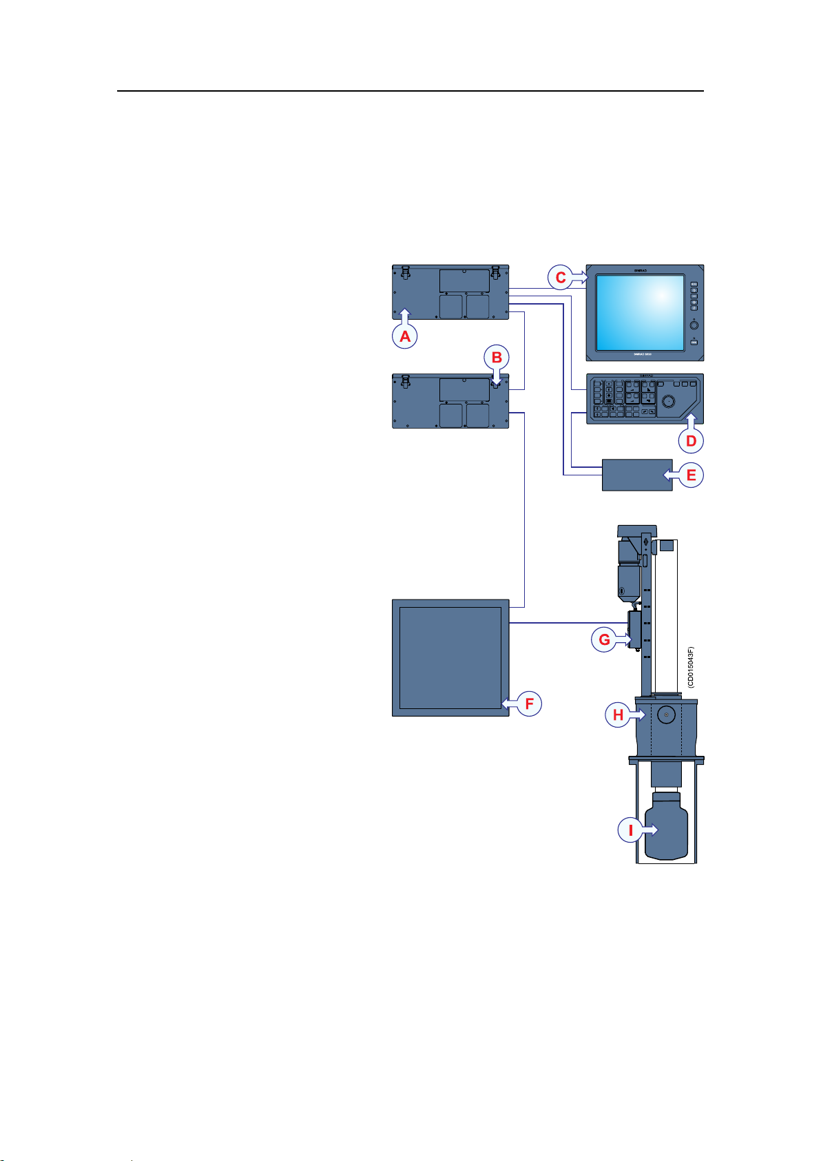
Systemdiagram
Figure1SX90Systemdiagram
SX90Items
AProcessorUnit
BBeamformerUnit
CColourdisplay
DOperatingPanel
EInterfaceUnit
FTransceiverUnit
GMotorControlUnit
HHullUnit
ITransducer
18
307531/C
Page 21

Scopeofsupply
ThestandardSimradSX90Fishndingsonarsystemis
comprisedofthefollowingmainunits.Allareincludedwiththe
standarddelivery.
•OperatingPanel[SH8-203593]
•ProcessorUnit[307664]
•BeamformerUnit[307666]
•InterfaceUnit[SP7-207891]
•TransceiverUnit(230V ac)[307668]
•SX92HullUnit[307476]
Additionalrequireditems
SimradSX90Fishndingsonar
Thefollowingadditionalitemsarerequiredforafullyoperational
sonar,buttheyaren
•Colourdisplay
•UninterruptedPowerSupply(UPS)
•Installationtrunk
•Speedlog
•Coursegyro
o t i n c l u d e d inthestandarddelivery:
Colourdisplay
TheSimradSX90FishndingsonarrequiresaVGAorDVI
colourdisplaywitharesolutionofatleast1280x1024pixels.
UninterruptedPowerSupply(UPS)
InordertoensurecontinuousoperationoftheSimradSX90
independentofvaryingqualityofthevessel’smainssupply,the
useofuninterruptedpowersupplies(UPS)isrequired.TwoUPS
unitsareused.Oneisusedtopowerthewheelhouseunits,while
theotherisusedtopowertheTransceiverUnit.
307531/C
19
Page 22

SimradSX90
Figure2NetProUPSunits
TheUPSunitsaren o t includedintheSX90standarddelivery.
WerecommendthatthefollowingUPSunitsareused:
WheelhouseUPSunit
•Manufacturer:GEDigitalEnergy
•Model:NetProNP1000
•Outputpower:1000V A/600W
•Physicaldimensions:
–Height:225mm
–Width:185mm
–Depth:430mm
–Weight:15kg
SonarroomUPSunit
•Manufacturer:GEDigitalEnergy
•Model:NetProNP2000
•Outputpower:2000V A/1200W
•Physicaldimensions:
–Height:293mm
–Width:220mm
–Depth:557mm
–Weight:27kg
Manufacturer
•GEDigitalEnergy
GeneralElectricCompany
CH–6595Riazzino(Locarno)Switzerland
w
w w . g e d i g i t a l e n e r g y . c o m
20
307531/C
Page 23

Installationtrunk
SimradSX90Fishndingsonar
Theinstallationtrunkrequiredforthehullunitinstallationisn
includedintheSX90standarddelivery.Theinstallationtrunk
maybefabricatedbytheshipyard,orsuppliedbySimradasan
option.Themechanicaldrawingsofthetrunkandblindcover
areincludedinthismanual.TheSimradSX90sonarisdelivered
withoutadomesystem.
TheoptionaltrunkofferedbySimradisapprovedbyDetNorske
Veritas(DNV),andincludesablindcoverandagasket.
Speedlog
Inordertooperatecorrectly,theSimradSX90Fishndingsonar
systemrequiresinputfromaspeedlog.Inmostcasesasuitable
sensorisalreadyinstalledonthevessel.Thespeedloginterface
parametersare:
•Pulselog:200pulsespernauticalmile
•Serialline:RS-232,StandardNMEA0183telegramformat
Adifferentialglobalpositioningsystem((D)GPS)canalsobe
used.
Relatedtopics
•Otherperipheralequipmentonpage23
o t
Additionaloptionalitems
Coursegyro
Inordertooperatecorrectly,theSimradSX90Fishnding
sonarsystemrequiresinputfromacoursegyro.Inmostcases
asuitablesensorisalreadyinstalledonthevessel.Thecourse
gyrointerfaceparametersare:
•Serialline:RS-232,StandardNMEA0183
IfthecoursegyroinstalleddoesnotoutputRS-232,anoptional
gyrointerfaceboxisavailable.Itwillconvertthefollowing
synchroandsteppinggyrosignals:
•3-phasesynchrosignal,20to150VL-L,50/60/400Hz,gear
ration1:360or1:180
•3-phasesteppersignal,20to150VL-L,gearration1:360or
1:180
GyrointerfaceOrderno.
LR40298-078535
Thefollowingoptionalequipmentandfunctionalitymaybe
orderedatanadditionalchargetoaugmentthestandardSimrad
SX90Fishndingsonarsystemdelivery.
307531/C
21
Page 24

SimradSX90
•Hullunitsandinstallationtrunks
•Additionalfunctionality:
–Scienticinterface
–Extendedrange
•Amplierwithoneortwospeakersforaudiooutput
•Otherperipheralequipmentandsensors
Optionalhullunitsandinstallationtrunks
Hullunits
ThestandardSX92HullUnitcanbelowered1.2metersataspeed
of24knots.Themountingangehas24boltswithpitchcentre
diameter(PCD)680mm.Otherhullunitsareavailableaslisted
below.
Table1HullunitsavailablefromSimrad
HullUnit
SX901.2m,24knots,20bolts,PCD620mm
SX911.6m,20knots,20bolts,PCD620mm
SX92*1.2m,24knots,24bolts,PCD680mm
SX931.6m,20knots,24bolts,PCD680mm
SX951,0m,12knots,16bolts,PCD540mm
(*=SX92isthestandardhullunit)
Note
SpecicationsOrderno.
307472
307474
307476
307478
310279
TheSimradSX90andSimradSX91hullunitsandtrunksare
discontinued.Theyareonlydeliveredonspecialorder .
Installationtrunks
Theinstallationtrunkmaybefabricatedbytheinstallation
shipyard,orsuppliedbySimrad.Severaltypesareavailablewith
variouspitchcentrediameters(PCD).
Table2OptionalinstallationtrunksavailablefromSimrad
Trunktype
SX90/SX9120bolts,PCD620mmSP9-205825
SX92/SX9324bolts,PCD680mmSP9-207516
SX9516bolts,PCD540mmSQ4–042508
22
SpecicationsOrderno.
307531/C
Page 25

SimradSX90Fishndingsonar
Note
TheSimradSX90andSimradSX91hullunitsandtrunksare
discontinued.Theyareonlydeliveredonspecialorder .
Optionalfunctionality
Extendedrange
Duetointernationalregulations,sonarswithoperationalrange
exceeding5000meterscanonlybeexportedonlicense.Forthis
reasonthestandardrangeontheSX90hasbeenlimitedto4500
meters.However,ifanexportlicenceisobtained,themaximum
rangecanbeextendedto8000meters.
OptionOrderno.
Extended8000mrange314506
Scienticinterface
Aspecialsoftwarekeycanbepurchasedtoenableanethernet
interfaceprovidingsonarbeamdata,sonarsettingsandprocessed
targetdata.Thisfeatureisveryusefulifthesonarisintended
forscienticpurposes.
OptionOrderno.
Scienticinterface
KIT-203477
Otherperipheralequipment
Inadditiontothepulseloginputdescribedabove,theSimrad
SX90FishndingsonarprovidesatotalofsevenRS-232
seriallines.Sinceoneisusedtointerfacethecoursegyro,the
remainingsixseriallinesmaybeusedfor:
•DifferentialGlobalPositioningSystem((D)GPS)
•Echosounder
•Catchmonitoringsystem
•Trawlsonar
•Currentmetersystem
•Radiobuoysystem
AlltheseperipheralsmaybeconnectedusingRS-232seriallines.
MostofthemwillcommunicatebymeansofthestandardNMEA
0183format.
307531/C
23
Page 26

SimradSX90
DifferentialGlobalPositioningSystem((D)GPS)
A(D)GPSmaybeinterfacedwiththeSimradSX90sonarto
establishthevessel’spositionandprovidecursorandmarker
latitudeandlongitude.Inadditiontonavigationaldata,the
(D)GPSmayalsobeusedfortheinputofspeedloginformation.
Most(D)GPSareequippedtopresentcourseinformation,but
thisdataisgenerallytooinconsistenttoprovideastablesonar
presentation.
Echosounder
Anexternalechosoundermaybeconnectedtothesonarto
providedepthinformationonthecatchcontrolpageofthe
sonar’sdisplay.
Catchmonitoringsystem
Toprovidetrawlandpurseseinedepthinformationonthesonar’s
display,thefollowingSimradcatchmonitoringsystemsmay
beconnected:
•SimradPI30Catchmonitoringsystem
•SimradPI32Catchmonitoringsystem
•SimradPI44Catchmonitoringsystem
•SimradPI54Catchmonitoringsystem
•SimradITIIntegratedTrawlInstrumentationsystem
Trawlsonar
Toprovidetrawlinformationonthesonar’sdisplay,oneofthe
followingSimradtrawlsystemsmaybeconnected:
•SimradFS903Trawlsonar
•SimradFS3300Trawlsonar
•SimradFS20/25Trawlsonar
•SimradFS70Trawlsonar
Currentmetersystem
Acurrentmetersystemmaybeconnectedtothesonartodisplay
thedirectionandspeedoftheseacurrentsonvariousdepths.The
followingcurrentsystemcanbeconnected:
•KaijoDCG-200
24
307531/C
Page 27

SimradSX90Fishndingsonar
Radiobuoysystem
AGPSbasedradiobuoysystemmaybeconnectedtothesonar
toshowthepositionandbuoydataonthedisplay.Thefollowing
buoysystemscanbeconnected:
•SERPE
•Ariane
•Ryokusei
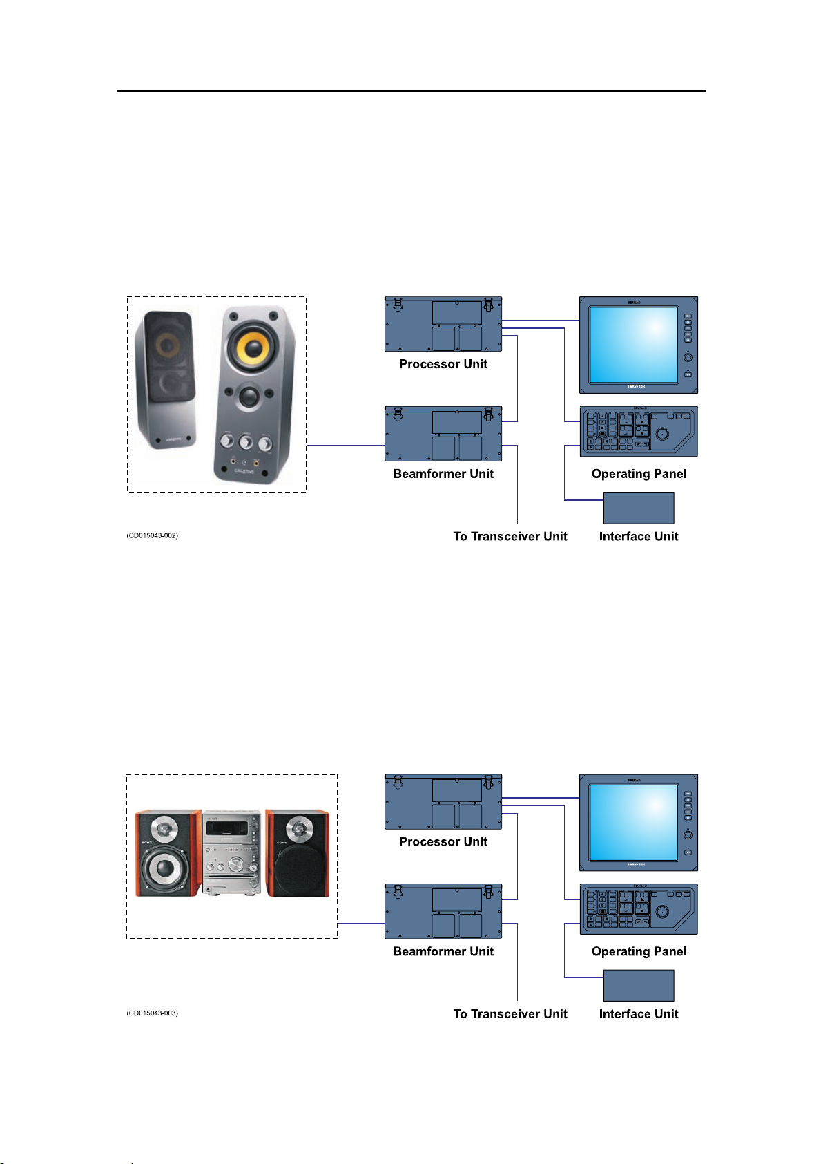
Optionalaudiooutput
TheSimradSX90Fishndingsonarsystemprovidesanaudio
output.Inordertousethisfunction,youmustconnectan
amplierwithspeakerstotheaudiooutputontheBeamformer
Unit.
Abouttheaudiooutput
TheaudiooutputontheSimradSX90Fishndingsonarisaline
output,andnopoweramplierisprovidedtocreatesound.The
audiooutputmustthereforebeconnectedtoapoweredaudio
system.Thesystemmustincludeavolumecontrol,astheaudio
outputlevelfromthesonarisxed.Theaudiooutputlevelcan
notbecontrolledbytheAudiooffbuttonontheOperatingPanel,
asthisbuttonwillsilencetheaudiooutputcompletely.
Note
Donotconnectaloudspeakerdirectlytotheaudiooutput.This
maydamagetheaudiooutputcircuitry.
Werecommendthatoneofthefollowingaudiosystemsisused:
•PoweredspeakersystemforPCuse
•Stereosystemwithamplierandtwoormoreloudspeakers
307531/C
25
Page 28
SimradSX90
PoweredspeakersystemforPCuse
AcommercialpoweredspeakersystemforPCusecanbe
obtainedfromalmostanykindofshopforelectricappliances,
homestereoorcomputers.
Figure3SonaraudiousingpoweredspeakersystemforPC
Thenumberofspeakers,sizeandpoweroutputcanbeselected
tosuitthecrewpreferences.Thelocationofthespeakersmustbe
decidedtoallowforeasyadjustmentoftheaudiolevel.
Stereosystemwithamplierandtwoormore
loudspeakers
Ifastereosystemisalreadyinstalledonthebridge,theaudio
outputfromthesonarcanbeconnectedtoanauxiliaryinput.
Figure4Sonaraudiousingexistingstereosystem
26
307531/C
Page 29

Generalsupplyconditions
SimradSX90Fishndingsonar
Theadvantageofthissetupisthatmoststereosystemsare
providedwitharemotecontrol,andthisallowsforeasy
adjustmentoftheaudiolevel.
ThefollowingsupplyconditionsareapplicabletothisSimrad
SX90Fishndingsonardelivery.
Equipmentresponsibility
Theshipyardperformingtheinstallationand/orequipmentdealer
becomesfullyresponsiblefortheequipmentuponreceiptunless
otherwisestatedinthecontract.Thedurationofresponsibility
includes:
•Theperiodoftimetheequipmentisstoredlocallybefore
installation.
•Duringtheentireinstallationprocess.
•Whilecommissioningtheequipment.
•Theperiodoftimebetweencommissioningandthenal
acceptanceoftheequipmentbytheenduser(normallythe
ownerofthevesselwhichtheequipmenthasbeeninstalled).
Unlessotherarrangementshavebeenmadeinthecontract,the
SX90Fishndingsonarsystemguaranteeperiod(asspeciedin
thecontract)beginswhentheacceptancedocumentshavebeen
signed
Receipt,unpackingandstorage
Uponacceptingshipmentoftheequipment,theshipyardand/or
thedealershouldensurethatthedeliveryiscompleteandinspect
eachshippingcontainerforevidenceofphysicaldamage.If
thisinspectionrevealsanyindicationofcrushing,dropping,
immersioninwateroranyotherformofdamage,therecipient
shouldrequestthatarepresentativefromthecompanyusedto
transporttheequipmentbepresentduringunpacking.
Allequipmentshouldbeinspectedforphysicaldamage,i.e.
brokencontrolsandindicators,dents,scratchesetc.during
unpacking.Ifanydamagetotheequipmentisdiscovered,the
recipientshouldnotifyboththetransportationcompanyand
SimradsothatSimradcanarrangeforreplacementorrepairof
thedamagedequipment.
Onceunpacked,theequipmentmustbestoredinacontrolled
environmentwithanatmospherefreeofcorrosiveagents,
excessivehumidityortemperatureextremes.Theequipment
mustbecoveredtoprotectitfromdustandotherformsof
contaminationwhenstored.
307531/C
27
Page 30

SimradSX90
Generalinstallationrequirements
Relatedtopics
•Equipmenthandlingonpage178
Thefollowinginstallationrequirementsareapplicabletothis
SimradSX90Fishndingsonardelivery.
Approvalbyclassicationsociety
TheSX90Fishndingsonartransducerinstallationmustbe
approvedbyDetNorskeV eritas(DNV)oranotherclassication
society.Theshipownerandshipyardperformingtheinstallation
areresponsibleforobtaininginstallationapproval.
Supplypower
Thesupplyvoltagetotheequipmentistobekeptwithin±10%of
theinstallation’snominalvoltage.Maximumtransientvoltage
variationsonthemainswitchboard’sbus-barsarenottoexceed
-15%to+20%ofthenominalvoltage(exceptunderfault
conditions).
SimradrecommendsthattheSX90Fishndingsonarispowered
usinganUninterruptablePowerSupply(UPS)withsinewave
output.TheUPSmusthavethecapacitytoindependently
maintainpowertothesystemforaminimumof10minutes.
Thisensuresthatthesystemcanbeswitchedoffinacontrolled
mannerintheeventofapowerfailure.
Compassdeviation
Oncetheinstallationiscomplete,thevesselmustbeswungwith
thesysteminboththeoperativeandinoperativemodes.The
shipownerandcaptainareresponsibleforupdatingthedeviation
tableaccordinglywithregardtothevessel’snationalregistryand
correspondingmaritimeauthority.
Noisesources
Thevessel’shull,rudder(s)andpropeller(s)shouldbethoroughly
inspectedindrydockpriortoinstallation.Roughnessbelow
thewater-linedeformitiesintheshellplatingandprotruding
obstaclescancreateunderwaternoise.Thesesourcesof
turbulencemustbesmoothedorremovedasbestaspossible.Itis
especiallyimportantthatthepropeller(s)isnotpittedordamaged.
28
307531/C
Page 31

SimradSX90Fishndingsonar
Drydocking
Makesurethatampleclearanceunderthesonartrunkand/or
protectionblisterisprovidedwhendrydockingthevessel.Avoid
locatingsupportingblocksorstructuresinthevicinityofthis
equipment.
Note
Thelocationofthetransducerand/orprotectionblistermustbe
notedonthevessel’ sdockingplanforfuturereference.
Powerdownallhydroacousticsystems,andlabeleachsystem
accordinglytopreventaccidentalpoweron.Removecircuit
breakersifnecessary.
Wiring
Allcablesrunningbetweensystemcabinetslocatedindifferent
roomsand/orondifferentdecksmustbesupportedandprotected
alongtheirentirelengthsusingconduitsand/orcabletrays.Note
thatthecablesmustnotbeinstalledinthevicinityofhigh-power
suppliesandcables,antennacablesorotherpossiblesources
ofinterference.
Formoredetailedinformationaboutcablesandwiring,referto
Basiccablerequirementsonpage214
307531/C
29
Page 32

SimradSX90
INSTALLATIONPLANNING
Note
Forinstallationinapreviouslyinstalledtrunksystem,rstread
theinformationaboutsonarroomrequirements.Thenproceed
totheHullUnitinstallationdescription.
Thischapterprovidesthemarineengineersresponsiblethe
informationnecessarytoplanandinstallthesonar’shullunit
accordingtoSimrad’srequirements.Correctinstallationofthe
sonartransducerisvitaltothesystem’sperformance.Several
variablesmustbetakenintoconsideration,themostimportant
ofwhichisthevessel’sconstruction.Thisguideisforusein
selectingthebestlocationforthetransducerandincludesabrief
descriptionofareastobeavoided.
Topics
Aboutinstallationdrawings
•Aboutinstallationdrawingsonpage30
•Locationofthehullunitonpage31
•Sonarroomrequirementsonpage32
•Sonarroomarrangementexampleonpage34
Allinstallationdrawingsmustbesuppliedbytheshipyard
performingtheinstallation.
Note
Theinstallationmustbeapprovedbythevessel’ snationalregistry
andcorrespondingmaritimeauthorityand/orclassication
society.Theshipownerandshipyardperformingtheinstallation
areresponsibleforobtainingandpayingforinstallation
approval.
Simradoffersfreeadviceforinstallationplanning.Proposed
arrangementsmaybesentforcommentaryorsuggestions
suppliedbySimrad.Thefollowingdrawingsshouldbesubmitted
shouldassistanceberequested:
•Generalarrangement
•Bodyplananddrawingsofrelevantbottomtanksand
cofferdams
•Linesplan
30
307531/C
Page 33

Locationofthehullunit
Foreandaft
Thehullunitshouldpreferablybelocatedwithin1/3to1/10
ofthevessel’sLengthBetweenPerpendiculars(LBP)fromits
ForwardPerpendicular(FP).Deviationsshouldnotbemade
withoutconsultingSimrad.
Athwartships
ThehullunitmaybelocatedontheCentreLine(CL)ofthe
vessel,oralongsideitskeel.Iftheinstallationisoffsetfromthe
vessel’scentreline,makesurethattransducertransmissionand
receptionwillnotbeobstructedbythekeel.
Figure5Locationofthehullunit
Installationplanning
AWaterlevelatnormaltrim
BW eldingmarkstoindicatehullunitlocationwhendocking
CLengthBetweenPerpendiculars(LBP)
D1/3to1/10ofLBP
Importantconsiderationsrelatedtonoise
Theinstallationtrunkmustbeinstalledsothatitwillremain
verticalundernormaloperatingconditions.Theprimarysources
ofunderwaterdisturbance(otherthanavessel’smainpropeller
andbow/sternthruster)thataffecttransducerreceptionare:
307531/C
31
Page 34

SimradSX90
Sonarroomrequirements
•Mainorbilgekeels
•Zincanodes
•Coolingelementsprotrudingfromthehull
•Equipmentsuchassonartransducersandpilottubes
•Seachests
•Overboarddischarges
•Dentsinthehull
Allappendagestothehull,indentationsandpipein/outletsare
potentialsourcesofunderwaternoise.Theymayactasresonant
cavitiesamplifyingnoiseatcertainfrequencies,createcavitation
orturbulence.Transducersshouldnotbelocatedinthevicinity
ofsuchobjectsandespeciallynotimmediatelyaftofthem.
Itisstronglyrecommendedtouseadedicatedcompartmentto
housethehullunitandthetransceivercabinet.Thesetwounits
mustalsobeinstalledrelativelyclosetoeachotherduetothe
limitedlengthofthetransducercables.Observetheseminimum
sonarroomrequirementstoobtainsuitableworkingconditions
forsonarinstallation,useandmaintenance.
Sizeandaccess
Awelldesignedsonarroomreducestheriskofcorrosionand
simpliesmaintenanceincreasingsystemreliability.
•Thesonarroommustbedimensionedtohousealltherelevant
cabinetsthatcomprisetheSX90Fishndingsonar.
•ThephysicaldistancebetweentheTransceiverUnitandthe
hullunitislimitedduetothelengthofthetransducercables.
•Thesonarroommustnotbeunnecessarilyobstructedby
girders,pipesetc.whichmightcauseinstallationproblemsor
impedemaintenance.
•Thesonarroommustbeaccessibleunderallconditionsat
seaorataberth.
•Alldoorsorhatchesmustbedesignedsothattheequipment
canberemovedwithoutbeingdisassembled.
Heating
Thesonarroommustbeequippedwithheater,dimensionedto
maintaintheequipmentwithinitsenvironmentaltolerances(at
least1000W),installedclosetothedeck.Heatingisalsoan
effectivemethodforreducinghumidity.
32
307531/C
Page 35

Installationplanning
Insulation
Bulkheadsmustbeinsulatedandprovidedwithaninteriorwall
tothedeck.Theinsulationshouldbetheminimumequivalent
of50mmofrock-wool.Inaddition,pipingpassingthroughthe
spacepronetocondensationmustbeinsulated.
Ventilation
Thesonarroommustbeconnectedtothevessel’sventilation
system.Ifthisisnotpossible,two3”ventsmustbeprovided
fromthesonarroomtothemaindeck.Intheroom,theairinlet
mustwheneverpossiblebelocatedclosetothedeckandthe
outletashighaspossible.Afunnelshapeddrip-collectormustbe
mountedbelowtheventpipestodivertmoisturetothebilge.On
themaindeck,thebestventilationisprovidedwhentheoutlet
pipeisatleastfourmetershigherthantheinletpipe.Tokeep
outseawater,rainandspray,theventilationpipesshouldbe
ttedwithgoosenecksortheequivalent.Ifthevesselislikely
tooperateintropicalconditions,asuitableairconditioning
systemmustbeinstalled.Thissystemmustbeabletoprovide
anambienttemperaturenotexceedingthemaximumoperating
temperaturesforthecabinetsinstalledintheroom.
Cableprotection
Ifthecablesbetweenthesonarroomequipmentandothersystem
unitslocatedindifferentcompartmentsonthevesselpass
throughhatchesorareaswheretheymaybedamaged,theymust
berunthroughconduits(minimum2”conduitisrecommended).
Electricalinstallationsandlights
Thesonarroommustbeequippedwithsuitablelightingto
simplifytheinstallationandtoaidfuturemaintenance.A
minimumnumberofelectricaloutletsmustbeprovidedforthe
systemunitsandotherequipment.
Bilgepumpanddecking
Thesonarroommustbeconnectedtothevessel’sbilgepump
system.Ifthisisnotpossible,aseparatebilgepumpforthe
sonarroommustbeinstalled.Oncetheinstallationhasbeen
completed,thesonarroommustbesuitablydeckedwithout
restrictingaccesstotheequipment.
Liftingdevice
Anattachmentpoint,ratedataminimumoftwo-2-tons,for
supportingaliftingdeviceshouldbelocatedabovethehullunit.
Thispermanentlyinstalledxturewillfacilitateinstallation
trunkandhullunitmounting,andalsomaybeusedforfuture
equipmentmaintenanceorreplacement.
307531/C
33
Page 36

SimradSX90
Removable
support
brackets
Transducercable
(Totallength4m)
Hatch
(min.680x1000)
TransceiverUnit
Ladder
500(*)
1600(*)
Allmeasurementsinmm
(*)=recommendedminimum
1600(*)
650(*)
150(*)
(CD015408A)
Sonarroomarrangementexample
Thesedrawingsillustrateatypicalsonarroomwithamplespace
forhullunit,transceiverunitandpersonnel.
Figure6Sonarroomarrangementexample,topview
34
307531/C
Page 37

Figure7Sonarroomarrangementexample,sideview
Airventpipes
(Min.diameter50mm)
Minimum4000mm
25
3000mm
(recommended+liftingdevice)
Loadcapacity
minimum2tonnes
Heater
TransceiverUnit
Pipes(10mm)
Airbleedingpipe
(Min.diameter10mm)
Lighting
1200mm(Recommended)
2115mm
(+400mmforSX91
andSX93)
250mm(minimum)
870mm
1600mm(SX91andSX93)
1200mm(SX90andSX92)
Max.1010mm
Min.910mm
(CD015408B)
Installationplanning
307531/C
35
Page 38

SimradSX90
SONARTRUNKINSTALLATION
Thesonartrunkprovidesthephysicalfoundationfortheentire
hullunitgantry .Thetrunkfurtherpenetratesthehull,anditis
thereforeacrucialpartofthehullunitassembly.Inorderto
ensurepropersonaroperation,thelocationofthesonartrunk
mustbecarefullyselected.
Note
Thisinstallationmanualdoesnotdescribetheinstallationofthe
SX95HullUnit.Forinformationaboutthatparticularhullunit,
refertothededicatedSimradSX95HullUnitinstallationmanual.
Atrunkwithablindcover–approvedbyDetnorskeV eritas
(DnV)–canbeorderedfromSimradasanoptionaldelivery,orit
maybemanufacturedbytheinstallationshipyardbasedonthe
drawingsinthismanualandthepropertiesofthehull.
Note
Theinstallationshipyardmustprovideallnecessaryinstallation
drawings,andifrequired,thesemustbeapprovedbythe
applicableauthorities.SeeAboutinstallationdrawingson
page30.
Topics
•Mountingthesonartrunkonpage37
•Sonartrunkprotectiononpage38
•Sonartrunkinstallationprinciplesonpage38
•Sonartrunkinstallationmeasurementsonpage41
Hullunitoutlinedimensiondrawings
•SX90Hullunitdimensionsonpage161
•SX91Hullunitdimensionsonpage162
•SX92Hullunitdimensionsonpage163
•SX93Hullunitdimensionsonpage164
•SX90/SX91Mountingtrunkdimensionsonpage165
•SX92Mountingtrunkdimensionsonpage167
•SX93Mountingtrunkdimensionsonpage169
•SX90/SX91Optionaltrunkdimensionsonpage171
•SX92Optionaltrunkdimensionsonpage172
•SX93Optionaltrunkdimensionsonpage173
•SX90/SX91Blindcoverdimensionsonpage174
•SX92Blindcoverdimensionsonpage175
36
307531/C
Page 39

•SX93Blindcoverdimensionsonpage176
Paralleltothe
centreline
(CD015404D)
Mountingthesonartrunk
Thelocationofthesonartrunkmustbecarefullyselected.
Note
Notetheorientationofthecentrelineofthetrunkwithregardto
themountingbolts.
Removethegasketonthetopangeduringwelding.
Figure8Orientationofthesonartrunk
Sonartrunkinstallation
Theheightfromthetopofthetrunkangetotheundersideof
theprotectionblistermustbeselectedasshownintheguresin
sectionSonartrunkinstallationprinciplesonpage38.
307531/C
37
Page 40

SimradSX90
Sonartrunkprotection
Note
Inordertoobtainoptimalsonarperformance,thetotalheight
ofthetrunkmustbeascloseaspossibletoitsstatedminimum
height.
Thetopangemustbeparalleltotheconstructionwaterlinein
boththefore-and-aftandathwartshipdirections.
Theinstallationtrunkmustbeweldedtoadoublingplatewhich
mustbeatleast1.5timesasthickasthesurroundingshellplating.
Thedoublingplate’snaldimensionsaretobegovernedbythe
approvedinstallationdrawingssuppliedbytheshipyard.The
trunkmustalsobestiffenedbyweldingknee-platestoitandthe
doublingplateinboththefore-and-aftandathwartshipdirections.
Protectingtheblister
Asteelblistermustbettedforprotection.Theblistershown
isweldedtotheshellplatingandthenlledwithoiltoprevent
corrosion.Thismethodprovidesexcellentprotectionand
simpliesmaintenance.
Corrosionprotection
Assoonasallinstallation,weldingandgrindinghasbeen
performed,thetrunkandthesurroundingareashouldbeprimed
andpaintedusingaqualityprotectivecoating.
Sonartrunkinstallationprinciples
Observethenexttwodrawings,theseillustratetheinstallation
ofthesonartrunk.
38
307531/C
Page 41

B
D
A
Fore-and-aftview
3-4knee-plates,mustbe
weldedtoframesorfloors
A:Asshortaspossible
B:Max.471/4"(1200mm)
C:Min.19/16"(40mm)
D:Min.357/8"(910mm)
E:Min.24"(610mm)
C
2.5-3xE
Thicknessofplates:
Knee-plates3/8"(10mm)
Blisteranddeflection
bracket1/4"(6mm)
Thecircularopeningofthe
blistershouldhavea
diameterequaltotheinside
diameterofthetrunk.
Deflection-bracketsshould
beweldedonlytothe
shell-plating.
Bottomview
Sideview
(CD015404N)
E
CD015404NPage1of2
Note:
Allmeasurementsareininchesandmm.
Thedrawingisnotinscale.
Sonartrunkinstallation
Figure9Installationofatrunkwithopenblister
307531/C
39
Page 42

2.5-3xE
B
D
A
Fore-and-aftview
Thicknessofplates:
Knee-plates3/8"(10mm)
Blisteranddeflection
bracket1/4"(6mm)
Thecircularopeningofthe
blistershouldhavea
diameterequaltotheinside
diameterofthetrunk.
Deflection-bracketsshould
beweldedonlytothe
shell-plating.
3-4knee-plates,mustbe
weldedtoframesorfloors
Plugforfillingofoil
Bottomview
A:Asshortaspossible
B:Max.471/4"(1200mm)
C:Min.19/16"(40mm)
D:Min.357/8"(910mm)
E:Min.24"(610mm)
Sideview
C
E
CD015404NPage2of2
Note:
Allmeasurementsareininchesandmm.
Thedrawingisnotinscale.
SimradSX90
Figure10Installationofatrunkwithoillledblister
40
307531/C
Page 43

Sonartrunkinstallationmeasurements
Sonartrunkinstallation
Forfuturereference,themeasurements“A”,“B”,“C”and“D”
fromthedrawingmustbemadeandnotedinthetablebelow.
Table3Trunkinstallationmeasurements
MillimetersInches
“A”
“B”
“C”
“D”
307531/C
41
Page 44

SimradSX90
HULLUNITINSTALLATION
ThischapterdescribesthephysicalinstallationoftheSimrad
SX90HullUnit.
Note
Thisinstallationmanualdoesnotdescribetheinstallationofthe
SX95HullUnit.Forinformationaboutthatparticularhullunit,
refertothededicatedSimradSX95HullUnitinstallationmanual.
Thehullunitisacrucialpartofthesonarsystem.Duetoits
physicalsizeandweight,andthefactthatthetrunkpenetrates
thevesselhull,itisveryimportantthatthehullunitisinstalled
andsecuredproperly.
Note
Theinstallationshipyardmustprovideallnecessaryinstallation
drawings,andifrequired,thesemustbeapprovedbythe
applicableauthorities.SeeAboutinstallationdrawingson
page30.
Topics
•Hullunitmodelsoverviewonpage43
•Howtounpackthehullunitfromitstransportboxonpage44
•Hullunitmountingonpage45
•Bleedingaircockonpage47
•Mechanicalsupportonpage47
•Transduceralignmentonpage47
•Hullunitinstallationchecklistonpage48
Relatedtopics
•Hullunitfamiliarizationonpage93
Hullunitoutlinedimensiondrawings
•SX90Hullunitdimensionsonpage161
•SX91Hullunitdimensionsonpage162
•SX92Hullunitdimensionsonpage163
•SX93Hullunitdimensionsonpage164
•SX90/SX91Mountingtrunkdimensionsonpage165
•SX92Mountingtrunkdimensionsonpage167
•SX93Mountingtrunkdimensionsonpage169
•SX90/SX91Optionaltrunkdimensionsonpage171
•SX92Optionaltrunkdimensionsonpage172
42
307531/C
Page 45

Hullunitmodelsoverview
SX90
SX92SX95
SX91
SX93
(CD015401-001)
Hullunitinstallation
•SX93Optionaltrunkdimensionsonpage173
•SX90/SX91Blindcoverdimensionsonpage174
•SX92Blindcoverdimensionsonpage175
•SX93Blindcoverdimensionsonpage176
TheSimradSX90sonarmaybedeliveredwithanyoneof
severaldifferenthullunitmodels.
Figure11SX90Hullunitmodels
•SX90:Thishullunithas1.2mstrokelength,anditis
designedformaximumspeed24knots.Itwilltontheold
Simradtrunkwith620mmpitchcentrediameter(PCD).
•SX91:Thishullunithas1.6mstrokelength,anditis
designedformaximumspeed20knots.Itwilltontheold
Simradtrunkwith620mmpitchcentrediameter(PCD).
•SX92:Thisisthe"standard"hullunitfortheSX90sonar.It
has1.2mstrokelength,anditisdesignedformaximumspeed
24knots.ItwilltonastandardSimradtrunkwith680mm
pitchcentrediameter.
307531/C
43
Page 46

SimradSX90
(CD015412B)
BB
C
A
•SX93:Thishullunithas1.6mstrokelength,anditis
designedformaximumspeed20knots.Itwilltonastandard
Simradtrunkwith680mmpitchcentrediameter.
•SX95:Thishullunithas1.0mstrokelength,anditis
designedformaximumspeed12knots.Itwilltonastandard
Simradtrunkwith540mmpitchcentrediameter.
Howtounpackthehullunitfromitstransportbox
Note
Thetransducerisprotectedtopreventdamageduringtransport
andhullunitinstallation.Thisprotectionmustremainattached
whilethehullunitisbeingmanoeuvredintothesonarroom.
Figure12Removingthehullunitfromitstransportbox
ALiftingeyeonthehoistingunit
BMountinghardware(woodencradleandsupport
construction)
CTransducerprotection
Procedure
1Removethetopcoverofthewoodenbox.
2Toremovethefasteninghardware(B),pulloutthenails
markedwithIndianink.
3Ifyouwishtoreusetheboxtoholdtheoldhullunit,make
surethatyoukeepallthefasteninghardwareusedtosecure
thehullunitinthewoodenbox.
4Fastentheliftingtackletothetwoliftingeyebolts(A)
onthetopofthehoistingunitandliftthehullunit(with
thetransducerprotectioninplace)carefullyoutofthe
transportationbox.
44
307531/C
Page 47

Hullunitinstallation
(CD015412C)
A
Note
Donotremovethetransducerprotection(C)fromthe
transduceruntiljustbeforethehullunitisloweredontothe
mountingtrunk.
Figure13Usethecorrectliftingeye!
Therearetwolifting
eyesoneachsideof
thehullunit:one
onthehoistingunit
andoneonthetopof
thetransducershaft.
Makesurethatyouuse
theliftingeyeonthe
hoistingunit(A)when
youliftthehullunitout
ofthetransportation
box!
5Ensurethatyoukeepthetransducercableandconnectordry.
Watchthesecarefullytopreventthemfrombeingdamaged,
stuckorhookedontoprotrudingobjectswhilemanoeuvring
thehullunitintothesonarroom.
Hullunitmounting
Thehullunitshouldnormallybeorientedwiththe
hoisting/loweringmotorpointingaft.Ifthisorientationmakes
theMotorControlUnitattachedtothehullunitdifcultto
access,thehullunitmaybeorientedinthemostsuitableposition.
307531/C
45
Page 48

SimradSX90
(CD015401B)
Bow
Figure14Orientationofthehullunit
Note
TheMotorControlUnitmustneverbephysicallydismounted
fromtheHullUnit.
Hullunitmountingprocedure
Tomakesurethattheprocedureisfollowed,tickoffeachtask
afterithasbeendone.
1
Useatackletolowerthehullunit(withthetransducer
protectioninplace)intothesonarroom
2Removetheblindcoverfromthetrunkandcheckthat
thegasketisnotdamaged.
3
Storetheblindcoverinthesonarroomforpossible
futureuse.
4Removethetransducerprotectionandlowerthehull
unitcarefullyontothetrunk.
5
Tightentheangenutswithatorqueofapproximately
470Nm.(OntheSX95hullunit,use140Nm.)
6Keepthetransducercableandconnectordry,and
handlethemwithgreatcaretopreventmechanicaldamage.
46
307531/C
Page 49

Bleedingaircock
(CD015401C)
A
B
C
Figure15Bleeding
aircock
Hullunitinstallation
Toavoiddamagetothetransducerby
thetransmissioninairinsidethetrunk,
apipewithaminimuminsidediameter
of10mmmustbeattachedtotheair
bleedingcock.Thisventshouldberun
withcontinuousrisetothemaindeck
orthroughthevessel’sside.Make
suretheairbleedingcockisopened.
AMinimum10mminternal
diameter
B3/8”pipethread
CV alveshowninopenedposition
Mechanicalsupport
Transduceralignment
Note
Toensurethesafetyofthesonarsystemandthevessel,itisvery
importantthatthemechanicalsupportofthehullunitgantry
issatisfactory.
Topreventunwantedvortexinducedvibration,thehullunit
mustbesecuredtothebulkhead.Usethetwopre-drilledholes
onthegantrytomountsupportbracketsinthefore-and-aftand
sidewaysdirection.Itmustbepossibletoremovethesupport
bracketsifmaintenanceisrequired.
Note
Ifyoudonotinstallapropermechanicalsupportforthehullunit
gantry,theguaranteewillbevoid!
Eventhoughyoumayhaveinstalledthehullunitoriented
differentlythanshowninthischapter,thetransducershalln o t
bemechanicallyaligned.
307531/C
47
Page 50

SimradSX90
TransduceralignmentisperformedintheSX90ProcessorUnit
byrotatingtheechopresentationonthedisplay.Thisisdescribed
insectionAlignmentofthesonarpictureonpage122.
Hullunitinstallationchecklist
Performaclosevisualinspectionofthesonarroomandthe
physicalinstallationofthehullunit.Refertothesonarroom
requirements,andllinthetablebelow.
Table4Hullunitinstallationchecklist
Item
Aretheaccesshatchessatisfactory?
Istheheatingsatisfactory?
Istheinsulationsatisfactory?
Istheventilationsatisfactory?
Istheairventpipesatisfactory?
Isabilgepumpinstalled?
Istheroomlightingsatisfactory?
Isthesonarroomsuitablydecked?
Isthemechanicalsupportofthehullunit
satisfactory?
DoyouhavesatisfactoryaccesstotheMotor
ControlUnit?
IftheanswertoanyofthesequestionsisNO,notethedeciencies
intheInstallationremarksandsignature.
Relatedtopics
•Sonarroomrequirementsonpage32
YESNO
48
307531/C
Page 51

TRANSCEIVERUNITINSTALLATION
TransceiverUnitpreparations
Transceiverunitinstallation
ThischapterexplainshowtoinstalltheSimradSX90Transceiver
Unit.Itisnormallypositionedinasonarroomclosetothehull
unit.
Topics
•TransceiverUnitpreparationsonpage49
•TransceiverUnitinstallationprocedureonpage49
Relatedtopics
•Sonarroomrequirementsonpage32
FreebulkheadspaceisrequiredtomounttheTransceiverUnit
cabinet.
Note
TheTransceiverUnitmustbemountedasacompleteunit.The
doormustnotbeopeneduntiltheunitissecurelyfastenedto
thebulkhead.
BeforeyoumounttheTransceiverUnit,observethatthedistance
betweentheHullUnitandtheTransceiverUnitisrestrictedby
theexibletransducercablejoiningthetwo.Remembertotake
intoconsiderationtheslacknecessarytolowerthetransducer.
o n o t fastenthetransducercabletotheTransceiverUnituntil
D
describedlaterinthestart-upprocedure.
Note
Theinstallationshipyardmustprovideallnecessaryinstallation
drawings,andifrequired,thesemustbeapprovedbythe
applicableauthorities.
TransceiverUnitinstallationprocedure
Observethefollowingprocedure.Toensurecorrectoperation,
tickoffeveryitemwhentheactionhasbeencarriedout.
1
2
3
307531/C
Removethetwomountingbracketswhicharefastened
totheshockabsorbersontheTransceiverUnit.
•UsetheAllenkeyfoundintheplasticbagfastenedto
theuppershockabsorber.
Weldthemountingbracketssecurelytothebulkhead.
UseachainfallorsimilardevicetolifttheTransceiver
Unitintopositionandboltittothemountingbrackets.
49
Page 52

SimradSX90
(CD15027G)
A
B
C
680±5mm
680±2mm
D
D
•Notethateightboltsareprovidedintheplasticbag
fastenedtotheuppershockabsorber.
4
ConnectthegroundingcablefromtheTransceiverUnit
tothemountingbracket.
Figure16Installationofmountingbrackets(1)
ADeckhead
BBulkhead
CDeck
DAnglebarswiththreadedholes
forshockabsorbers.Thesebars
aresuppliedbySimrad.
50
307531/C
Page 53

Transceiverunitinstallation
(CD015027H)
(1)
(2)
(3)
(4)
(5)
(1) (1)
470±10mm
A
B
C
D
D
Figure17Installationofmountingbrackets(2)
ADeckhead
BBulkhead
CDeck
DAnglebarswiththreadedholesforshockabsorbers.These
barsaresuppliedbySimrad.
1Minimum150mmtoclosestdeckheadand/orbulkhead
2Recommendeddistancebetween1100and1200mm.
Minimumdistance300mm.
3Approximately40mm.
4Approximately70mm.
5Minimum75mm.
307531/C
51
Page 54

SimradSX90
Figure18Installationoftransceiver
AUppershockabsorber
BTransceiverUnit
CHeatExchanger
DGroundingcable
EGroundingcable,detail
52
307531/C
Page 55

WHEELHOUSEUNITSINSTALLATION
Wheelhouseunitsinstallation
ThischapterexplainshowtoinstalltheSimradSX90hardware
unitsnormallypositionedinthewheelhouse.Theseunitsinclude:
•ProcessorUnit
•BeamformerUnit
•InterfaceUnit
•Colourdisplay
•OperatingPanel
Note
Theinstallationshipyardmustprovideallnecessaryinstallation
drawings,andifrequired,thesemustbeapprovedbythe
applicableauthorities.
Topics
•Physicallocationofwheelhouseunitsonpage53
•Maximumdistancesbetweentheunitsonpage56
•Installationofthedisplayunitonpage57
•InstallationoftheOperatingPanelonpage57
•InstallationoftheProcessorUnitonpage58
•InstallationoftheBeamformerUnitonpage59
•InstallationoftheInterfaceUnitonpage60
•Installationoftheaudiosystemonpage61
Physicallocationofwheelhouseunits
Onboardroutinesandthelistedinstallationrequirementsmust
bethoroughlydiscussedwiththecaptainwhenselectingthe
locationsfortheOperatingPanelandcolourdisplay.
Installationrequirements
Installationofthewheelhouseunitsmustbeperformedby
qualiedandtrainedpersonnelwithregardto:
•Thesafenavigationofthevessel
•The"Compasssafedistance"foreachindividualunit.
•Ergonomicallycorrectoperatingandviewingheights.
•Maximumallowablecabledistancesbetweenthevarious
units.
•Theinstallationareasaredry,wellventilatedandfreeof
excessivedustandvibration.
•Easyaccesstothecableconnectionsonthebackofthe
equipmentisprovided.
307531/C
53
Page 56

SimradSX90
•Enoughextracableisallowedtofacilitatemaintenanceand
servicebynothavingtodisconnectthecables.
Locationofthecolourdisplay
Thedisplayunitshouldbelocatedsothatitisbestprotected
fromglarewhichreducesreadability.Itmaybe:
•Panelmounted
•Desktopmounted
•Bulkheadmounted
•Overheadmounted
Refertothedisplayunit’sinstructionmanualforthecompass
safedistance.Ifseveralcolourdisplaysaremountedinthe
wheelhouseforusewithvarioussonars,echosoundersandradar
systems,wesuggestthatyouinstalladisplayselectordevice.A
displayselectorwillallowyoutosetupthesonar(oranyother
system)tobeviewedonanydisplay ,andthismaybechosen
dependingonthecurrentoperationstakingplace.Ifacommercial
displayisused,observetheminimumtechnicalrequirements.
LocationoftheOperatingPanel
TheOperatingPanelprovidedwiththeSimradSX90contains
allthecontrollersforthesonaroperation.Thebuilt-intrackball
allowsyoutooperatethemenusystemonthesonar,but
additional“short-cut”buttonshavealsobeenprovidedtoaccess
themostcommonfunctionsdirectly.Testshaveshownthatthis
allowsyoutooperatethesonarfaster,anditreducesfatigue.
WerecommendthattheOperatingPanelismountedinanearly
horizontalposition,andwithineasyviewingrangeofthedisplay
unit.Thecompasssafedistancestobeallowedforwhenplanning
theunit’slocationare:
•StandardCompass:0.05m.
•SteeringCompass:0.05m.
LocationoftheProcessorUnit
TheProcessorUnitshouldbeinstalledinsideaconsole,ina
cabinetoronadesk.Makesurethatadequateventilationis
availabletoavoidoverheating.Thecompasssafedistancestobe
allowedforwhenplanningtheunit’slocationare:
•StandardCompass:0.15m.
•SteeringCompass:0.1m.
54
307531/C
Page 57

Wheelhouseunitsinstallation
LocationoftheBeamformerUnit
TheBeamformerUnitshouldbeinstalledinsideaconsole,in
acabinetoronadesk.Makesurethatadequateventilationis
availabletoavoidoverheating.Thecompasssafedistancestobe
allowedforwhenplanningtheunit’slocationare:
•StandardCompass:0.15m.
•SteeringCompass:0.1m.
LocationoftheInterfaceUnit
TheSonarInterfaceUnitshouldbemountedverticallywiththe
cableinletdownwardsonasidewallinsideaconsole,cabinetor
desk.Provideenoughspaceforeasyaccessforcableconnections
totheunit.Thecompasssafedistancetobeallowedforwhen
planningtheunit’slocationare:
•StandardCompass:TBDm.
•SteeringCompass:TBDm.
Locationoftheaudiosystem
Theaudiosystemmustincludeanamplierandoneormore
loudspeakers.Choosingalocationandinstallationoftheitems
shouldbedonewithregardtothefunctionalityprovided,such
asaccesstothevolumecontrol.Theoutputfromthesonar
systemmayalsobeconnectedtoanexistingstereosysteminthe
wheelhouse.Thecompasssafedistancetobeallowedforwhen
planningthelocationoftheaudiosystemdependsonthetypeof
systemused.
307531/C
55
Page 58

SimradSX90
Maximumdistancesbetweentheunits
Observethemaximumdistancesbetweenthewheelhouseunits.
Figure19Maximumdistancesbetweenthewheelhouseunits
Allmeasurementsareinmeters.
AProcessorUnit
BBeamformerUnit
CInterfaceUnit
DColourdisplay
EOperatingpanel
FEthernetcabletoTransceiverUnit
56
307531/C
Page 59

Installationofthedisplayunit
372mm
Nutplate
152mm
401.9mm
ø7x4
(CD015022M)
Differentdisplayunitsareavailableasoptionalequipment.For
installationandoperationofthechosendisplayunit,refertothe
manualsuppliedwiththeunit.
Installationprocedure
Toensurecorrectoperation,tickoffeveryitemwhentheaction
hasbeencarriedout.
Wheelhouseunitsinstallation
1
Installthedisplayunitasdescribedtheapplicable
documentationprovidedwiththeunit.
Relatedtopics
•Maximumdistancesbetweentheunitsonpage56
InstallationoftheOperatingPanel
Installationprocedure
TheOperatingPanelisdesignedtoberecessedinapanel.
Toensurecorrectoperation,tickoffeveryitemwhentheaction
hasbeencarriedout.
1
2
3
MounttheOperatingPanelinanalmosthorizontal
positiontofacilitateoperationofthetrackball.
•Thenecessarymountinghardware(fourscrews,fournut
platesandfourboltcovers)aresuppliedinthestandard
delivery.
Drillandcutthepanelopeningasshowninthegure.
MounttheOperatingPanelusingthesupplied
hardware.
307531/C
APositionthefournutplatesshowninthegure.
Figure20OperatingPanelcut-out
57
Page 60

SimradSX90
BUsea3mmAllenkeytofastenthefourspecialbolts.
CMounttheboltcoversinthefourcornersofthe
OperatingPanel.
Relatedtopics
•Maximumdistancesbetweentheunitsonpage56
•OperatingPaneldimensionsonpage160
InstallationoftheProcessorUnit
TheProcessorUnitshouldbemountedonthedeckorshelf
insideaconsole,cabinetordesk.Itmustbemountedclosetothe
InterfaceUnit,OperatingPanelanddisplayunit.Provideenough
spaceforeasyaccesstothecablingattherearoftheunitandfor
removalofthefrontlid.
Installationprocedure
Toensurecorrectoperation,tickoffeveryitemwhentheaction
hasbeencarriedout.
1
2
Preparethemountinglocation.
Dismountthemountingframewiththeshockabsorbers
fromthecomputerbylooseningthetwofasteningscrewson
thefront,andpullthecomputerassemblyforwards.
3
Placeandsecurethemountingframewithsixboltsor
screwstothebasement.Thediameteroftheholesare7mm.
4
Re-attachthecomputerunittothemountingframeby
guidingitbackwardsuntilthelockingpinsatthebottomof
thecomputerassemblyndthecorrectpositions.Securethe
assemblywiththetwofasteningscrewsonthefront.
58
307531/C
Page 61

Wheelhouseunitsinstallation
(CD015006C)
A
B
D
C
Figure21InstallationoftheProcessorUnit
AComputerassembly
BLockingpin
CMountingframewithshockabsorbers
DFasteningscrews
Relatedtopics
•Maximumdistancesbetweentheunitsonpage56
•MC80ProcessorUnitdimensionsonpage158
InstallationoftheBeamformerUnit
TheBeamformerUnitshouldbemountedonthedeckorshelf
insideaconsole,cabinetordesk.Itmustbemountedclosetothe
InterfaceUnit,OperatingPanelanddisplayunit.Provideenough
spaceforeasyaccesstothecablingattherearoftheunitandfor
removalofthefrontlid.
Installationprocedure
Toensurecorrectoperation,tickoffeveryitemwhentheaction
hasbeencarriedout.
1
2
307531/C
Preparethemountinglocation.
Dismountthemountingframewiththeshockabsorbers
fromthecomputerbylooseningthetwofasteningscrewson
thefront,andpullthecomputerassemblyforwards.
59
Page 62

SimradSX90
(CD015006C)
A
B
D
C
3 Placeandsecurethemountingframewithsixboltsor
screwstothebasement.Thediameteroftheholesare7mm.
4Re-attachthecomputerunittothemountingframeby
guidingitbackwardsuntilthelockingpinsatthebottomof
thecomputerassemblyndthecorrectpositions.Securethe
assemblywiththetwofasteningscrewsonthefront.
Figure22InstallationoftheBeamformerUnit
AComputerassembly
BLockingpin
CMountingframewithshockabsorbers
DFasteningscrews
Relatedtopics
•Maximumdistancesbetweentheunitsonpage56
•MC81BeamformerUnitdimensionsonpage159
InstallationoftheInterfaceUnit
TheInterfaceUnitshouldbemountedverticallywiththecable
inletdownwardsonasidewallinsideaconsole,cabinetordesk.
ItmustbemountedclosetotheProcessorUnit,OperatingPanel
anddisplayunit.Makesurethatyouprovideenoughspacefor
easyaccesstothecabling.
60
307531/C
Page 63

Wheelhouseunitsinstallation
149mm
Ø7mm
253mm
(CD015029G)
Installationprocedure
Toensurecorrectoperation,tickoffeveryitemwhentheaction
hasbeencarriedout.
1
2
Preparethemountinglocation.
MounttheInterfaceUnitverticallywithfourfastening
screwsontheattachmentlugs.Thediameterofthefour
fasteningholesare7mm.
Figure23InstallationoftheInterfaceUnit
Relatedtopics
•Maximumdistancesbetweentheunitsonpage56
•InterfaceUnitdimensionsonpage157
Installationoftheaudiosystem
307531/C
Differentareavailableforlocalpurchase.Forinstallation
andoperationofthechosensoundsystem,refertothemanual
suppliedwiththeunit.
Relatedtopics
•Optionalaudiooutputonpage25
61
Page 64

SimradSX90
UPSINSTALLATION
InordertoensurecontinuousoperationoftheSimradSX90
independentofvaryingqualityofthevessel’smainssupply,the
useofuninterruptedpowersupplies(UPS)isrequired.TwoUPS
unitsareused.Oneisusedtopowerthewheelhouseunits,while
theotherisusedtopowertheTransceiverUnit.
Theinstallationoftheseunitsmustbeperformedasdescribed
intheapplicabledocumentationprovidedbythemanufacturer.
EnsurethatyouinstalltheUPSunitinsuchawaythat
maintenanceiseasilycarriedout.
TheUPSunitsrecommendedbySimradarelistedinsection
Additionalrequireditemsonpage19.
Relatedtopics
•UninterruptedPowerSupply(UPS)onpage19
62
307531/C
Page 65

Cablelayoutandinterconnections
CABLELAYOUTANDINTERCONNECTIONS
Pleasendprovidedtheinstallationproceduresandrequirements
fortheSimradSX90systemcables.Theseinstructionsmustbe
usedtogetherwiththecableplan.
Note
Allelectronicinstallationsandcorrespondingwiringmustbein
accordancewiththevessel’ snationalregistryandcorresponding
maritimeauthorityand/orclassicationsociety.ObserveBasic
cablerequirementsonpage214.
Ifnosuchguidelinesexist,werecommendthatDetNorske
Veritas(DNV)ReportNo.80-P008«GuidelinesforInstallation
andProposalforTestofEquipment»isusedasaguide.
Topics
•Cableplanonpage64
•Listofcablesonpage66
•Cableproceduresonpage72
•Referencestocabledetailsanddrawingsonpage90
Relatedtopics
•Cablingprinciplesonpage189
•Cablestoperipheraldevicesonpage190
•Cabledrawingsonpage194
•Basiccablerequirementsonpage214
307531/C
63
Page 66

SimradSX90
Cableplan
Figure24Wheelhousecables
Wheelhouseitems
ABeamformerUnit
BProcessorUnit
CInterfaceUnit
DDisplayUnit
EOperatingPanel
FUninterruptedPowerSupply
GEthernetcabletoTransceiverUnit
HSerialinterfacecables
IExternalsynchronisation
JScienticoutput(Ethernet)
Cablesidentiedwithanasterisk(*)aresuppliedwiththe
sonar.
64
307531/C
Page 67

Figure25Sonarroomcables
Cablelayoutandinterconnections
Sonarroomitems
ATransceiverUnit
BUninterruptedPowerSupply
CMotorControlUnit
DHullUnit
ETransducer
F3–phasemains
GEthernetcabletowheelhouse
HEthernetcontroltoMotorControlUnit
ITransducercable
Cablesidentiedwithanasterisk(*)aresuppliedwiththe
sonar.
307531/C
65
Page 68

SimradSX90
Listofcables
Sonarcables
C1SX90/C01ACmainstocolourdisplay
Thiscableisprovidedwiththecolourdisplay.Itisa
standardcommercialcable.
•ConnectACmainstothecolourdisplayonpage81
•ACmainswithIEC320/C21onpage206
C2SX90/C02ACmainstoProcessorUnit
Thiscableisprovidedwiththesonar.Itisastandard
mainssupplycable.
•ConnectACmainsandgroundtotheProcessorUnit
onpage79
•ACmainswithIEC320/C21onpage206
C3SX90/C03ACmainstoBeamformerUnit
Thiscableisprovidedwiththesonar.Itisastandard
mainssupplycable.
•ConnectACmainsandgroundtotheBeamformer
Unitonpage80
•ACmainswithIEC320/C21onpage206
C4SX90/C04ACmainstoT ransceiverUnit
Thiscableisprovidedwiththesonar.Itisastandard
commercialitem.
•ConnectACmainstotheTransceiverUnitonpage82
•ACmainswithIEC320/C21onpage206
C5SX90/C05ACmainstoHeatExchanger
ThisisastandardACmainscable.Itisprovidedreadily
xedtotheheatexchangercabinet.
•ConnectACmainstotheHeatExchangeronpage88
•ACmainswithIEC320/C21onpage206
C6SX90/C06ACmainstoMotorControlUnit
Thiscablemustbeprovidedbytheinstallationshipyard.
ItisaspecialACmainscable.
•ConnectACmainstotheMotorControlUniton
page86
66
307531/C
Page 69

Cablelayoutandinterconnections
•ACmainstoMotorControlUnitonpage207
Note
Thiscablecanbepreparedforinstallation,butitmust
NOTbeconnectedtotheMotorControlUnituntil
specicallyinstructedbythesetupprocedure.
C7SX90/C07OperatingPaneltoground
Thiscablemustbeprovidedbytheinstallationshipyard.
Itisastandardcommercialgroundcable.
•ConnectgroundtotheOperatingPanelonpage84
•Vesselgroundonpage205
C8SX90/C08ProcessorUnittoground
Thiscablemustbeprovidedbytheinstallationshipyard.
Itisastandardcommercialgroundcable.
•ConnectACmainsandgroundtotheProcessorUnit
onpage79
•Vesselgroundonpage205
C9SX90/C09BeamformerUnittoground
Thiscablemustbeprovidedbytheinstallationshipyard.
Itisastandardcommercialgroundcable.
•ConnectACmainsandgroundtotheBeamformer
Unitonpage80
•Vesselgroundonpage205
C10SX90/C10VideocablefromProcessorUnittocolourdisplay
Thiscableisnormallyprovidedwiththedisplay.Itisa
standardcommercialcable.
•ConnectthevideocablefromtheProcessorUnittothe
colourdisplayonpage74
•VGA/SVGADisplayonpage209
•DVI–IDisplayonpage211
C11SX90/C11OperatingPanelUSBcabletoProcessorUnit
Thiscableisprovidedwiththesonar.ItisastandardUSB
datacablewithlength4,5meters.
•ConnecttheUSBcablefromtheOperatingPanelto
theProcessorUnitonpage75
307531/C
67
Page 70

SimradSX90
•USBonpage210
C12SX90/C12OperatingPanel“Dualcable”toProcessorUnit
andInterfaceUnit
Thiscableisprovidedwiththesonar.Itisaspecialdual
cablewithonecommon15-pinconnectorleadingtotwo
separate9-pinconnectorsinthetwootherendsofthe
cable.Thecablelengthis4,5meter.
•ConnecttheOperatingPanel“Dualcable”onpage76
•OperatingPanel“Dual”onpage213
C13SX90/C13InterfaceUnittoground
Thiscablemustbeprovidedbytheinstallationshipyard.
Itisastandardcommercialgroundcable.
•ConnectgroundtotheInterfaceUnitonpage83
•Vesselgroundonpage205
C14SX90/C14InterfaceUnittoProcessorUnit(I)
Thisisaspecialinterconnectioncableprovidedwiththe
sonar.Thecablelengthis1.2m.Theconnectorwillonly
titsrespectivesocketinslotJ8ontherearsideofthe
ProcessorUnit.
•ConnectthetwocablesfromtheInterfaceUnittothe
ProcessorUnitonpage77
•InterfaceUnittoProcessorUnitonpage195
C15SX90/C15InterfaceUnittoProcessorUnit(II)
Thisisaspecialinterconnectioncableprovidedwiththe
sonar.Thecablelengthis1.2m.Theconnectorwillonly
titsrespectivesocketinslotJ7ontherearsideofthe
ProcessorUnit.
•ConnectthetwocablesfromtheInterfaceUnittothe
ProcessorUnitonpage77
•InterfaceUnittoProcessorUnitonpage195
C16SX90/C16ACmainstoUninterruptedPowerSupplyinthe
wheelhouse
ThisisastandardACmainscable.Itisprovidedwiththe
UninterruptedPowerSupply.IftheACmainsconnector
onthecabledoesnott,replaceitwithasuitable
connector.
68
307531/C
Page 71

Cablelayoutandinterconnections
•ConnectACmainstotheUninterruptedPowerSupply
onpage73
•ACmainswithIEC320/C21onpage206
C17SX90/C17ACmainstoUninterruptedPowerSupplyinthe
sonarroom
ThisisastandardACmainscable.Itisprovidedwiththe
UninterruptedPowerSupply.IftheACmainsconnector
onthecabledoesnott,replaceitwithasuitable
connector.
•ConnectACmainstotheUninterruptedPowerSupply
onpage73
•ACmainswithIEC320/C21onpage206
C18SX90/C18BeamformerUnittoexternalaudiosystem
Thiscablemustbeprovidedbytheinstallationshipyard.
Thecableisconnectedtoanexternalaudiosystem.
•Connectcabletoexternalaudiosystemonpage89
•Commercialcablewithmini-jackonpage196
C19Notused
C20SX90/C20Speedlog
Thiscablemustbeprovidedbytheinstallationshipyard.
Theconnectiontothespeedlogisessentialforsonar
operation.ThespeedlogisconnectedtotheInterface
Unit.
•Connectingthespeedlogonpage131
•Speedloginterfacetestonpage134
•Pulsespeedloginterfaceonpage198
•RS-232totheInterfaceUnitonpage200
Note
Theoutputfromapulselogmustn e v e r beconnectedto
morethanonesystemsimultaneously.Ifitisconnectedto
thesonar,d
o n o t usethesameoutputtofeedothersystems.
C21SX90/C21Coursegyro
Thiscablemustbeprovidedbytheinstallationshipyard.
Theconnectiontothecoursegyroisessentialforsonar
operation.ThecoursegyroisconnectedtotheInterface
Unit.
307531/C
69
Page 72

SimradSX90
•Connectingthecoursegyroonpage133
•Coursegyrointerfacesetupandtestonpage136
•RS-232totheInterfaceUnitonpage200
C22SX90/C22Seriallineinterface
TheInterfaceUnitprovidesatotalofsevenRS-232serial
lines.Oneisnormallyusedtointerfacethecoursegyro,
andoneisusedtointerfaceaspeedlog.Thisleavesyou
withveorsixseriallinesthatcanbeusedtointerface
otherperipheralsystems,suchascatchmonitoring
systems,echosoundersorothernavigationsystems.
•Cablestoperipheraldevicesonpage190
•InterfaceUnitseriallinesonpage197
C23SX90/C23Seriallineinterface(sameasC22)
C24SX90/C24Seriallineinterface(sameasC22)
C25SX90/C25Seriallineinterface(sameasC22)
C26SX90/C26Seriallineinterface(sameasC22)
C27SX90/C27Seriallineinterface(sameasC22)
C28SX90/C28Synchronisation
TheInterfaceUnitprovidesaninterfacelinethatallows
youtosynchronisethesonarwithanexternalsystem.
Thisexternalsystemcouldbeanechosounder,asecond
sonar,oranyotheracousticsystemworkinginthesame
frequencyrangeasthesonar.Usingthisinterface,the
sonarcanbesetupasa“Master”inthesynchronized
system.
•Externalsynchronisationinterfaceonpage199
C29Notused
C30SX90/C30EthernetcablefromtheProcessorUnittothe
BeamformerUnit
Thiscableisprovidedwiththesonar.ItisaCA T -6
Ethernetcable.
•ConnecttheProcessorUnittotheBeamformerUnit
onpage78
•RJ45Ethernet,straightonpage208
C31SX90/C31EthernetcablefromtheBeamformerUnittothe
TransceiverUnit
70
307531/C
Page 73

Cablelayoutandinterconnections
Thiscablemustbeprovidedbytheinstallationshipyard.
ItisaCA T -6Ethernetcable.
•ConnecttheBeamformerUnittotheTransceiverUnit
onpage85
•RJ45Ethernet,straightonpage208
Note
ItisveryimportantthataCAT -6(orCAT-7)Ethernet
cableisused.Cableswithlowerbandwidthcapacitywill
reducethesonarperformance.
C32SX90/C32EthernetcablefromtheTransceiverUnittothe
MotorControlUnit
Thiscableisprovidedwiththesonar.Partnumberis
312152.ItisaCA T-6Ethernetcable,anditis8meters
long.
•ConnecttheTransceiverUnittotheMotorControl
Unitonpage87
•RJ45Ethernet,straightonpage208
C33SX90/C33Scienticoutput
Thiscablemustbeprovidedbytheinstallationshipyard.
ItisaCA T -6Ethernetcable.
•ConnecttheEthernetcableforscienticoutputon
page89
•RJ45Ethernet,straightonpage208
C34Notused
C35SX90/C35Transducercable
307531/C
71
Page 74

SimradSX90
Cableprocedures
Observethefollowingproceduretoperformthesonarcabling.
Notethatdetailedinformationaboutcablespecications,
terminationandconnectorsareprovidedinthereferenced
sections.AllcablesareprovidedbySimradunlessotherwise
specied.Inordertoprovideformaintenanceandtoallowfor
vibration,makesurethatsomeslackisprovidedforallcables.
Tomakesurethateachprocedureisfollowed,tickoffeachtask
afterithasbeendone.
Note
Beforeyouperformthesonarcabling,ensurethatthemains
circuitbreakerforthesonarsystemisswitchedoff.
o n o t mounttheexibletransducercabletotheTransceiver
D
Unit.Thiswillbedescribedlater.
Topics
•ConnectACmainstotheUninterruptedPowerSupplyon
page73
•ConnectthevideocablefromtheProcessorUnittothecolour
displayonpage74
•ConnecttheUSBcablefromtheOperatingPaneltothe
ProcessorUnitonpage75
•ConnecttheOperatingPanel“Dualcable”onpage76
•ConnectthetwocablesfromtheInterfaceUnittothe
ProcessorUnitonpage77
•ConnecttheProcessorUnittotheBeamformerUniton
page78
•ConnectACmainsandgroundtotheProcessorUniton
page79
•ConnectACmainsandgroundtotheBeamformerUniton
page80
•ConnectACmainstothecolourdisplayonpage81
•ConnectACmainstotheTransceiverUnitonpage82
•ConnectgroundtotheInterfaceUnitonpage83
•ConnectgroundtotheOperatingPanelonpage84
•ConnecttheBeamformerUnittotheTransceiverUniton
page85
•ConnectACmainstotheMotorControlUnitonpage86
•ConnecttheTransceiverUnittotheMotorControlUniton
page87
72
307531/C
Page 75

Cablelayoutandinterconnections
•ConnectACmainstotheHeatExchangeronpage88
•ConnecttheEthernetcableforscienticoutputonpage89
•Connectcabletoexternalaudiosystemonpage89
•Transducercableonpage90
•Installationofinterfacecablestoperipheralequipmenton
page90
ConnectACmainstotheUninterrupted PowerSupply
TherearetwoUninterruptedPowerSupply(UPS)locations;the
sonarroomandthewheelhouse.StandardcommercialACmains
cablesareused,andtheseareprovidedwiththeUninterrupted
PowerSupplyunits.IftheACmainsconnectorsonthecabledo
nott,replacethemwithasuitableconnector.
Procedure
ThesearecablesSX90/C16andSX90/C17.
1
ConnecttheUninterruptedPowerSupplyinthe
wheelhousetothevessel’sACmains.
2ConnecttheUninterruptedPowerSupplyinthesonar
roomtothevessel’sACmains.
Relatedtopics
•ACmainswithIEC320/C21onpage206
307531/C
73
Page 76

SimradSX90
ConnectthevideocablefromtheProcessor
Unittothecolourdisplay
Thisisastandardcommercialcable.Itisoftenphysically
attachedtothedisplay,andterminatedinthe“computerend”
withamale15-pinDeltaconnector(VGA)oraspecialDVI
connector.ThegraphicadapterontherearsideoftheProcessor
Unitprovidestwoconnectors,oneforVGAandoneforDVI-I.
Choosetheconnectorthattsyourcable.Ifyouhavetwo
displaysbothcanbeconnectedsimultaneously,buttheywill
showthesamepicture.
Procedure
ThisiscableSX90/C10.
1
Connectthedisplaycablefromtheappropriatesloton
therearsideoftheProcessorUnittothedisplayunit.
Figure26Displaycableconnections
Relatedtopics
•VGA/SVGADisplayonpage209
•DVI–IDisplayonpage211
74
307531/C
Page 77

Cablelayoutandinterconnections
ConnecttheUSBcablefromtheOperating
PaneltotheProcessorUnit
ThisisastandardcommercialUSBdatacable.Itconnects
betweentheOperatingPanelandtheProcessorUnit.Thecable
lengthis4,5meters.IthasaquadraticUSBconnectorinthe
OperatingPanelend(B-plug),andrectangularUSBconnectorin
theProcessorUnitend(A-plug).
Procedure
ThisiscableSX90/C11.
1
ConnectthecablefromtheB-typeUSBconnector
undertheOperatingPaneltooneofthevacantUSB
connectorsontherearsideoftheProcessorUnit.
Figure27USBcableconnections
2SecuretheconnectorundertheOperatingPanelwithacable
strip.
Relatedtopics
•USBonpage210
307531/C
75
Page 78

SimradSX90
ConnecttheOperatingPanel“Dualcable”
ThisisaspecialdualcablefromtheOperatingPaneltothe
ProcessorUnitandtheInterfaceUnit.Thiscablehasone
common15-pinconnectorleadingtotwoseparate9-pin
connectorsinthetwootherendsofthecable.Thecableis
includedinthestandarddelivery,andthecablelengthis4,5
meter.Thecableisconnectedasfollows:
•15-pinD-connector(commonend)toOperatingPanel.
•9-pinfemaleD–connectortoInterfaceUnitsocketJ4.
•9-pinmaleD–connectortoProcessorUnitslotJ2.
Procedure
ThisiscableSX90/C12.
1
ConnectthesingleendofthecabletotheD-connector
undertheOperatingPanel.
2ConnectoneendtotheD-connectorinslotJ2onthe
rearsideoftheProcessorUnit
3
ConnectthethirdendtotheD-connectorinsidethe
InterfaceUnit.
Figure28TheOperatingPanel“Dualcable”connections
Relatedtopics
•OperatingPanel“Dual”onpage213
76
307531/C
Page 79

Cablelayoutandinterconnections
ConnectthetwocablesfromtheInterface
UnittotheProcessorUnit
Thesearetwospecialinterconnectioncablesprovidedwiththe
sonar.Bothare1,2meterslong,andconnectedpermanentlyto
theInterfaceUnitend..
•CableC14communicatesthecontrolsignalsbetweenthe
ProcessorUnitandtheInterfaceUnit.Thecableisequipped
witha37-pinfemaleDeltaconnectorontheProcessorUnit
end.Theconnectorwillonlytitsrespectivesocketinslot
J8ontherearsideoftheProcessorUnit.
•CableC15communicatestheserialinformationbetweenthe
InterfaceUnitandtheProcessorUnit.Thecableisequipped
withaspecial78–pinmalemulti-connectorintheProcessor
Unitend.Theconnectorwillonlytitsrespectivesocketin
slotJ7ontherearsideoftheProcessorUnit.
Procedure
ThesearecablesSX90/C14andSX90/C15.
1
ConnectcableC14fromtheInterfaceUnittoslotJ8
ontherearsideoftheProcessorUnit.
2
ConnectcableC15fromtheInterfaceUnittoslotJ7
ontherearsideoftheProcessorUnit.
Figure29ThecablesfromtheInterfaceUnittotheProcessorUnit
Relatedtopics
•InterfaceUnittoProcessorUnitonpage195
307531/C
77
Page 80

SimradSX90
ConnecttheProcessorUnittothe BeamformerUnit
Procedure
ThisiscableSX90/C30.
1
Locatethe5meterreadilyterminatedEthernetcable
providedwiththeBeamformerUnit.
2
ConnecttheEthernetcablefromslotJ4ontherear
sideoftheProcessorUnittoslotJ4ontherearsideofthe
BeamformerUnit.
EachslotJ4providestwoEthernetconnector.Usethe
o t t o m connectorontheProcessorUnitandthet o p
b
connectorontheBeamformerUnit.
Figure30Connections
Relatedtopics
•RJ45Ethernet,straightonpage208
78
307531/C
Page 81

Cablelayoutandinterconnections
ConnectACmainsandgroundtothe ProcessorUnit
TheACmainscableisastandardcommercialitem.Itissecured
totherearsideoftheProcessorUnitwithabracket.Themains
voltagefortheProcessorUnitis115or230V ac,anditwill
automaticallysensethecurrentsupplyvoltage.IftheACmains
connectoronthecabledoesnott,replaceitwithasuitable
connector.
Procedure
ThesearecablesSX90/C02andSX90/C08.
1
ConnecttheUninterruptedPowerSupply(UPS)inthe
wheelhousetothevessel’sACmains.
2ConnecttheACmainscablefromtheUPStothe
ProcessorUnit.
3Mountthebrackettosecuretheconnectorontherear
sideoftheProcessorUnit.
4
ConnectthegroundingcabletotheProcessorUnit.
Note
Thegroundingcablemustbeprovidedbytheinstallation
shipyard.Itmustbeconnectedtothevessel’ sgroundinthe
fusebox(orothercommongroundingpoint).
Figure31ProcessorUnitACmainsandgroundingcables
Relatedtopics
•Vesselgroundonpage205
•ACmainswithIEC320/C21onpage206
307531/C
79
Page 82

SimradSX90
ConnectACmainsandgroundtothe BeamformerUnit
TheACmainscableisastandardcommercialitem.Itissecured
totherearsideoftheBeamformerUnitwithabracket.The
mainsvoltagefortheBeamformerUnitis115or230V ac,and
itwillautomaticallysensethecurrentsupplyvoltage.Ifthe
ACmainsconnectoronthecabledoesnott,replaceitwitha
suitableconnector.
Procedure
ThesearecablesSX90/C03andSX90/C09.
1
ConnecttheACmainscablefromtheUninterrupted
PowerSupply(UPS)inthewheelhousetotheBeamformer
Unit.
2
Mountthebrackettosecuretheconnectorontherear
sideoftheBeamformerUnit.
3ConnectthegroundingcabletotheBeamformerUnit.
Note
Thegroundingcablemustbeprovidedbytheinstallation
shipyard.Itmustbeconnectedtothevessel’ sgroundinthe
fusebox(orothercommongroundingpoint).
Figure32BeamformerUnitACmainsandgrounding
cables
Relatedtopics
•Vesselgroundonpage205
•ACmainswithIEC320/C21onpage206
80
307531/C
Page 83

Cablelayoutandinterconnections
ConnectACmainstothecolourdisplay
TheACmainscableisastandardcommercialitem.IftheAC
mainsconnectoronthecabledoesnott,replaceitwitha
suitableconnector.
Procedure
ThisiscableSX90/C01.
1
ConnecttheACmainscablefromtheUninterrupted
PowerSupplyinthewheelhousetothecolourdisplay.This
isastandardcommercialmainscable.
2
Connectagroundingcabletothecolourdisplayifthis
isspeciedintheinstallationinstructionsprovidedbythe
manufacturer.
Relatedtopics
•ACmainswithIEC320/C21onpage206
307531/C
81
Page 84

SimradSX90
ConnectACmainstotheTransceiverUnit
TheACmainscableisastandardcommercialitem.Itis
connectedtoasocketatthebottomoftheTransceiverUnit.If
theACmainsconnectoronthecabledoesnott,replaceitwith
asuitableconnector.
Procedure
ThisiscableSX90/C04.
1
ConnecttheACmainscablefromtheUninterrupted
PowerSupplyinthesonarroomtothebottomsocketon
theTransceiverUnit.Thisisastandardcommercialmains
cable.
Figure33TransceiverUnitACmainssocket(A)
Relatedtopics
•ACmainswithIEC320/C21onpage206
82
307531/C
Page 85

Cablelayoutandinterconnections
ConnectgroundtotheInterfaceUnit
Procedure
ThisiscableSX90/C13.
1
ConnectthegroundingcabletotheInterfaceUnit.
Aconnectionboltislocatedontherighthandsideofthe
unit.
Relatedtopics
•Vesselgroundonpage205
307531/C
83
Page 86

SimradSX90
ConnectgroundtotheOperatingPanel
Procedure
ThisiscableSX90/C06.
1
ConnectthegroundingcabletotheOperatingPanel.
Aconnectionboltislocatedundertheunit.
•Vesselgroundonpage205
Figure34GroundconnectionontheOperatingPanel
84
307531/C
Page 87

Cablelayoutandinterconnections
ConnecttheBeamformerUnittothe TransceiverUnit
Procedure
ThisiscableSX90/C31.
1
ConnecttheEthernetcablefromtheb o t t o m Ethernet
socketonslotJ4ontherearsideoftheBeamformerUnitto
i g h t EthernetsocketundertheTransceiverUnit.
ther
Note
Thiscablemustbeprovidedbytheinstallationshipyard.
UseacommercialCAT–6cable.Werecommendthatan
additionalspareethernetcableisinstalledbetweenthe
wheelhouseandthesonarroom.
ItisveryimportantthataCAT -6(orCAT-7)Ethernetcable
isused.Cableswithlowerbandwidthcapacitywillreduce
thesonarperformance.
EachendoftheEthernetcablemustbeterminatedwith
aPhoenixContact“V ariosubRJ45Quickcon”connector.
Twooftheseconnectorsareprovidedinthesonardelivery.
Mountinginstructionsareincludedwiththeplugassembly.
Figure35BeamformerUnittoTransceiverUnitconnections
Relatedtopics
•RJ45Ethernet,straightonpage208
307531/C
85
Page 88

SimradSX90
ConnectACmainstotheMotorControlUnit
Thisisaspecialmainscablefor3-phaseACmains.Itmust
beprovidedbytheinstallationshipyard.Observethecable
specications,seeACmainstoMotorControlUnitonpage207.
Procedure
ThisiscableSX90/C06.
Figure363–phaseACmainsconnections
1
Connectthe3–phaseACmainscablefromtheMotor
ControlUnittothevessel’s3-phaseACmains.
Note
Thiscablemustbeprovidedbytheinstallationshipyard.
Use4x2.5mm²cable,ensurethatthescreenisproperly
terminatedinthecablegland.
DONOTapply3–phasepowertotheMotorControlUnit
untilinstructedbytheapplicablestart-upprocedure.
Relatedtopics
•ACmainstoMotorControlUnitonpage207
86
307531/C
Page 89

Cablelayoutandinterconnections
ConnecttheTransceiverUnittotheMotor ControlUnit
Procedure
ThisiscableSX90/C32.
1
Locatethe8metersterminatedEthernetpatchcable
providedwiththeTransceiverUnit.
2
ConnecttheEthernetcablefromtheEthernetsocket
undertheTransceiverUnittotheEthernetsocketonthe
MotorControlUnit.
Figure37TransceiverUnittoMotorControlUnitconnections
307531/C
87
Page 90

SimradSX90
ConnectACmainstotheHeatExchanger
ThisisastandardACmainscable.Itisprovidedreadilyxed
totheheatexchangercabinet.IftheACmainsconnectoronthe
cabledoesnott,replaceitwithasuitableconnector.
Note
Themainsvoltagefortheheatexchangerise i t h e r 230V aco r
115V ac.Makesurethatyouhavethecorrectmainsvoltage.To
checktheratedpowerfortheheatexchanger ,seetheregistration
labelonthefrontoftheunit.
Procedure
ThisiscableSX90/C05.
1
ConnecttheACmainscableontheheatexchangerto
theUninterruptedPowerSupplyinthesonarroom.
Relatedtopics
•ACmainswithIEC320/C21onpage206
88
307531/C
Page 91

Cablelayoutandinterconnections
ConnecttheEthernetcableforscientic
output
Procedure
ThisiscableSX90/C32.
1
ConnecttheEthernetcablefromtheadditionalEthernet
socketontherearsideoftheProcessorUnit.
Note
Thiscablemustbeprovidedbytheinstallationshipyard.
UseacommercialCAT–6cable.
2 TerminatetheotherendoftheEthernetcableina
suitableaccesspointfortheship’snetwork.
Relatedtopics
•RJ45Ethernet,straightonpage208
Connectcabletoexternalaudiosystem
Procedure
ThisiscableSX90/C18.
Acommercialcableisused.Oneendmustbeterminatedwith
a“mini-jack”.Theotherendmustbeterminatedtomatchthe
audiosysteminput.
1
Connecttheaudiocablefromtheaudiooutputsocket
ontherearsideoftheBeamformerUnit.
Theoutputsocketisidentiedwithagreenring.
Figure38The(A)identiestheaudiooutputontherear
sideoftheBeamformerUnit
2 Terminatetheotherendoftheaudiocabletota
suitableinputonthesoundsystem.
Relatedtopics
•Commercialcablewithmini-jackonpage196
307531/C
89
Page 92

SimradSX90
Transducercable
ThetransducercableisprovidedbySimrad.Itisphysically
connectedtothetopofthetransducershaft,andterminatedinthe
otherendwithalargeconnector.
Note
D o n o t mounttheexibletransducercabletotheTransceiver
Unit.Thisoperationisdescribedlater .
Installationofinterfacecablesto peripheralequipment
TB1throughTB7intheInterfaceUnitareallRS-232serial
lineconnections.Thesemaybeusedtoconnecttoanyexternal
device.Forfurtherdetailsabouttheseconnections,referto:
•Cablestoperipheraldevicesonpage190
•Interfacingperipheralequipmentonpage128
Cabledrawings
•SonarandITIcommunicationonpage201
•SonarandFS20/25communicationonpage202
•SonarandPI44/PI54communicationonpage203
•SonarandPI30/PI32communicationonpage204
•Sonarseriallineonpage212
Referencestocabledetailsanddrawings
Alldetailedinformationaboutthecablesareprovidedinthe
appendix.
Cablespecications
•InterfaceUnittoProcessorUnitonpage195
•Commercialcablewithmini-jackonpage196
•InterfaceUnitseriallinesonpage197
•Pulsespeedloginterfaceonpage198
•Externalsynchronisationinterfaceonpage199
•RS-232totheInterfaceUnitonpage200
•SonarandITIcommunicationonpage201
•SonarandFS20/25communicationonpage202
•SonarandPI44/PI54communicationonpage203
•SonarandPI30/PI32communicationonpage204
•Vesselgroundonpage205
•ACmainswithIEC320/C21onpage206
90
307531/C
Page 93

Cablelayoutandinterconnections
•ACmainstoMotorControlUnitonpage207
•RJ45Ethernet,straightonpage208
•VGA/SVGADisplayonpage209
•USBonpage210
•DVI–IDisplayonpage211
•Sonarseriallineonpage212
•OperatingPanel“Dual”onpage213
307531/C
91
Page 94

SimradSX90
START-UPPROCEDURES
Theproceduresinthischaptershallbecarriedoutonceallthe
hardwareunitshavebeeninstalled,andthecablingisnished.
Note
Whenyoucarryouttheseprocedures,makesurethatyouonly
performthosetasksdescribed,andinthegivenorder .
Checkoffeveryitemintheprocedureasyoucarryon.
Topics
•StartinguptheHullUnitonpage92
•Startingupthewheelhouseunitsonpage102
•CheckingtheOperatingPanelonpage104
•StartinguptheTransceiverUnitonpage112
•Checkingthehoist/lowersystemonpage113
•Performself-noisetestonpage118
•Startingupthesonarsystemonpage119
•Alignmentofthesonarpictureonpage122
•Adjustingthestabilisationsensoroffsetonpage124
•Deningownshipparametersonpage125
StartinguptheHullUnit
ObservethefollowingproceduretostartuptheHullUnit.
WARNING
Beforeyoustartupthesonarequipmentona
recentlylaunchedvessel,makesurethatthedepth
underthekeelissufcientforthetransducerto
beloweredsafely.
Whenyoustartuptheequipmentonboarda
vesselindrydock,checkrstunderthevessel
andinsidethesonarroom.Personnel,toolsand
otherpotentialobstructionsmustbekeptclearof
thetransducerandrelatedloweringandhoisting
machinerytoavoidpersonalinjuryordamageto
theequipment.
92
307531/C
Page 95

Hullunitfamiliarization
(CD015404-008)
D
E
F
G
H
I
J
L
K
A
B
C
Figure39Hullunitfamiliarization
Start-upprocedures
AUpperlimitswitchS304
BTransducershaft
CLowerlimitswitchS305
DHandcrankformanual
hoistingandlowering
EHoistmotor
FBrakereleasescrew
GMotorControlUnit
HGantry
IMountingange
JInstallationtrunk
KTransducer
LTransducershaftsleeve
307531/C
93
Page 96

SimradSX90
(CD015409B)
HOIST STOP
REMOTE LOWER
E301
S301
S302 P302
S303
K303
L1
L2
K302K301
F301
B
A
Figure40MotorControlUnitfamiliarization
MotorControlUnitfamiliarization
(A)Internal24Vdcpowersupply
(B)Ethernetconnector
(F301)Fuseforinternalpower
supply
(E301)TerminalstripforAC
mainsinput
(K301)Hoistingcontactor
(K302)Loweringcontactor
(K303)Phasewatchrelay
Duringnormaloperationalconditions,thetwofollowing
indicatorlampsshallbelit:
•IndicatorlampL1indicatesthatthephasewatchrelayK303
isactivated.Thismeanthatthe3-phasevoltageisapplied
tothehoist/lowersystem,andthatthethreephasesare
correctlyconnectedwithregardtothetrainingdirectionof
thehoist/lowermotor.
(L1)Yellowindicatorlight
(L2)Greenindicatorlight
(S301)Motorprotectingswitch
(S302)Hoist/lowerselector
(S303)Handcrankwithsafety
switch
(P302)Connectorforhullunit
limitswitchesandrotationsensor
•IndicatorlampL2indicatesthattheinternal+24Vdcpower
supplyforthecontrolelectronicisoperational.
94
307531/C
Page 97

Start-upprocedures
Functionalcheck
Procedure
Beforeyoucommencewiththestart-upprocedure,checkthe
followingitems.
Tomakesurethattheprocedureisfollowed,tickoffeachtask
afterithasbeendone.
1
Checkthatthe3-phasemainsfusesaredisconnected
intheship’sfusebox.
2UseaspannertoopenthedoorontheMotorControl
UnitwhichismountedontheHullUnitgantry.
3LocatethemotorprotectingswitchS301,andcheck
thattheoperatinghandleispresseddowntoOFFposition.
4
Checkthatthehoist/lowerswitchS302intheMotor
ControlUnitissetintheSTOPposition.
307531/C
95
Page 98

SimradSX90
(CD015409K)
HOIST STOP
REMOTE LOWER
E301
S301
S302
Apply3-phaseACpower
Howtoapply3–phasepower
Tomakesurethattheprocedureisfollowed,tickoffeachtask
afterithasbeendone.
Figure41MotorControlUnitwithS301andE301
1 LocatethemotorprotectingswitchS301intheMotor
ControlUnit,andcheckthattheoperatinghandleispressed
downtoOFFposition.
2
Checkthatthehoist/lowerswitchS302intheMotor
ControlUnitissetintheSTOPposition.
3
Re-insertthe3-phasemainsfusesforthehullunitin
theship’sfusebox.
4
Measurethethree-phasevoltageontheterminalsE301
intheMotorControlUnit.
Writedownthemeasuredvoltagehere:
Supplyvoltage:
5 Adjustthereleasecurrentonthemotorprotecting
switchS301accordingtothethree-phasevoltage:
•230V ac:10A(maximum)
•380/440V ac:6,5A
96
307531/C
Page 99

Start-upprocedures
230Vac
380/440V ac
(CD015407A)
Checkthehoistmotor’s3–phaseAC connections
Procedure
Inordertoensurethatthehoistingmotoroperatesproperly,and
toavoidseriousdamagetothemotor,youmustcheckthatthe
motorconnectionsaremadeinaccordancewiththesupplied
3–phasevoltage.
Tomakesurethattheprocedureisfollowed,tickoffeachtask
afterithasbeendone.
1
Removethe3-phasemainsfusesforthehullunitin
thevessel’sfusebox.
2
Removethecoverforthemainsconnectiononthe
motor.
3
Refertotheillustration,andcheckifthemotor
connectionsaremadeinaccordancewiththesupplied
3–phasevoltage.
Figure42Mainsconnectiontothemotor
Note
Theorderoftheconnectionwiresmustnotbechanged!
4 Iftheconnectionsdonotmatchthe3–phasevoltage,
rewiretomakethemcorrespondtothemeasuredvoltage.
5
Adjustthereleasecurrentonthemotoroverloadswitch
S301accordingtothethree-phasevoltage:
•230V ac:10A(maximum)
•380/440V ac:6,5A
307531/C
97
Page 100

SimradSX90
(CD015409L)
HOIST STOP
REMOTE LOWER
E301
S301
S302
K303
L1
6 Re-insertthe3-phasemainsfusesforthehullunitin
thevessel’sfusebox.
Checkthe3–phaseconnectionforcorrect rotationdirection
Procedure
TheMotorControlUnitisequippedwithaPhaseWatchRelay
(K303),whichpreventsoperationofthehoist/lowermotorif
the3-phaseconnectionsarewrongwithrespecttothemotor’s
rotationdirection.
Figure43MotorControlUnitwithS302,S301,E301,K303
andLEDL1
98
Tomakesurethattheprocedureisfollowed,tickoffeachtask
afterithasbeendone.
1
Checkthatthehoist/lowerswitchS302intheMotor
ControlUnitissetintheSTOPposition.
2
SwitchonthemotorprotectingswitchS301bypressing
theoperatinghandleupwardstoONposition.
3
CheckthattheLEDL1onthefrontofthePhaseW atch
Relay(K303)islit.
4
IftheLEDisn o t lit,observethefollowingprocedure:
1Disconnecttheship’s3-phasefuses.
2Changetwoofthe3-phaseconnectionsontheterminal
E301intheMotorControlUnit.
3Re-insertthe3-phasefusesintheship’sfusebox.
307531/C
 Loading...