

Page 1

com
TECHNOLOG
SUS
S
Installation Manual
Simrad ST90
Fish nding sonar
Y FOR
TAINABLE FISHERIE
www.simrad.
Page 2

Page 3

SimradST90
Fishndingsonar
InstallationManual
Thepurposeofthismanualistoprovidetheinformation,procedures
andbasicdrawingsrequiredforthephysicalinstallationoftheSimrad
ST90.Themanualisintendedfortechnicalpersonnel;suchasskilled
shipyardworkers,electricians,qualiedengineersandnavalarchitects.
ForinformationaboutthepracticaluseoftheST90,refertotheST90
ReferenceManualand/ortheST90OperatorManual.Youcanalso
ndinformationintheST90ContextSensitiveOn-lineHelp.
Caution
Asasafetyprecaution,youmustneverturnontheST90whenthe
shipisindrydock.Thetransducermaybedamagedifittransmits
inopenair.
442703/B
July2019©KongsbergMaritimeAS
Page 4

Documentinformation
•Product:SimradST90
•Document:InstallationManual
•Documentpartnumber:442703
•DocumentISBNnumber:N/A
•Revision:B
•Dateofissue:5July2019
Copyright
TheinformationcontainedinthisdocumentremainsthesolepropertyofKongsberg
MaritimeAS.Nopartofthisdocumentmaybecopiedorreproducedinanyformorby
anymeans,andtheinformationcontainedwithinitisnottobecommunicatedtoathird
party,withoutthepriorwrittenconsentofKongsbergMaritimeAS.
Warning
Theequipmenttowhichthismanualappliesmustonlybeusedforthepurposefor
whichitwasdesigned.Improperuseormaintenancemaycausedamagetothe
equipmentand/orinjurytopersonnel.Y oumustbefamiliarwiththecontentsofthe
appropriatemanualsbeforeattemptingtooperateorworkontheequipment.
KongsbergMaritimedisclaimsanyresponsibilityfordamageorinjurycausedby
improperinstallation,useormaintenanceoftheequipment.
Disclaimer
KongsbergMaritimeASendeavourstoensurethatallinformationinthisdocumentis
correctandfairlystated,butdoesnotacceptliabilityforanyerrorsoromissions.
Supportinformation
Ifyourequiremaintenanceorrepair,contactyourlocaldealer.Y oucanalsocontactus
usingthefollowingaddress:simrad.support@simrad.com.Ifyouneedinformation
aboutourotherproducts,visithttps://www .simrad.com.Onthiswebsiteyouwillalso
ndalistofourdealersanddistributors.
KongsbergMaritimeAS
www.kongsberg.com
Page 5

InstallationManual
Tableofcontents
ABOUTTHISMANUAL............................................................15
SIMRADST90........................................................................17
Important..........................................................................................................................17
Systemdescription...........................................................................................................19
Keyfeatures.....................................................................................................................21
Systemdiagram................................................................................................................22
Systemunits.....................................................................................................................23
Displaydescription.................................................................................................23
ProcessorUnitdescription......................................................................................23
TransceiverUnitdescription..................................................................................24
OperatingPaneldescription...................................................................................26
Hullunitdescription...............................................................................................27
Transducerdescription...........................................................................................29
Installationtrunkdescription..................................................................................30
Scopeofsupply................................................................................................................32
Basicitemsprovidedwithastandarddelivery.......................................................32
Additionalrequireditems.......................................................................................35
Additionaloptionalitems.......................................................................................39
Generalsafetyrules..........................................................................................................46
Installationrequirements..................................................................................................47
Supplypowerrequirements....................................................................................47
UninterruptiblePowerSupply(UPS)requirements...............................................47
Cablesandwiringrequirements.............................................................................48
Compassdeviationrequirements............................................................................48
Noisesources..........................................................................................................49
Drydockingrequirements......................................................................................49
Requirementforclassicationapproval.................................................................49
Networksecurity..............................................................................................................50
Supportinformation.........................................................................................................51
PREPARATIONS.....................................................................53
Installationsummary........................................................................................................54
Aboutinstallationdrawings.............................................................................................57
Tools,equipmentandconsumablesrequiredforST90installation.................................57
Personnelqualications...................................................................................................58
Choosingthebestlocationforthehullunit.....................................................................59
Aboutthehullunitlocation....................................................................................59
Deningtheforeandaftlocationofthehullunit..................................................60
442703/B
3
Page 6

SimradST90
Deningtheathwartshipslocationofthehullunit................................................61
Importantconsiderationsrelatedtonoise...............................................................61
Locationofhardwareunitsonthebridge........................................................................62
Basicrequirementsforthelocationofbridgeunits...............................................62
Maximumdistancebetweeneachbridgeunit........................................................63
Choosingthebestlocationforthedisplay.............................................................64
ChoosingthebestlocationfortheProcessorUnit.................................................65
ChoosingthebestlocationfortheOperatingPanel...............................................65
Sonarroomrequirements.................................................................................................66
Aboutthesonarroom.............................................................................................66
Environmentalrequirements..................................................................................66
Requirementsforwatertightintegrity....................................................................67
Sizeandaccessrequirements.................................................................................68
Requirementsforinsulation,heatingandventilation.............................................68
Requirementsforelectricalinstallations,cablesandcommunication...................69
Requirementsforbilgepumpanddecking.............................................................70
Liftingrequirements...............................................................................................71
Orientationofthehullunit.....................................................................................72
Sonarroomarrangement:Topview.......................................................................73
Sonarroomarrangement:Sideview......................................................................74
Sonarroomarrangement:Sideview......................................................................75
Acousticnoise..................................................................................................................76
Introductiontotheacousticnoisechallenge..........................................................76
Contributingfactors................................................................................................76
Selfnoise................................................................................................................78
Ambientnoise.........................................................................................................80
Electricalselfnoise................................................................................................81
Reverberation.........................................................................................................81
Somemeanstoreduceacousticnoise....................................................................82
INSTALLINGTHEOPTIONALGATEVALVEDN500..................85
Gatevalveinstallationoverview......................................................................................86
Abouttheoptionalgatevalve..........................................................................................88
Gatevalvesystemdescription.........................................................................................89
Gatevalveinstallationprinciples.....................................................................................91
Mechanicalsupportbrackets............................................................................................93
Installingthemountingange.........................................................................................94
Mountingangeandmanualgatevalveinstallation..............................................97
Mountingangeandhydraulicgatevalveinstallation..........................................99
Installationexample.............................................................................................101
Installingthegatevalve.................................................................................................102
4
442703/B
Page 7

InstallationManual
Installingthetransducerdock........................................................................................103
Installingthehydraulicunits..........................................................................................105
Verifyingthequalityofthegatevalveinstallation........................................................106
MOUNTINGTHEINSTALLATIONTRUNK...............................109
Installationtrunkmountingoverview............................................................................110
Abouttheinstallationtrunk...........................................................................................112
O-ring...................................................................................................................113
Mechanicalsupportbrackets................................................................................114
Designandinstallationdrawings.........................................................................115
Mountingtheinstallationtrunk......................................................................................115
Mountingthetrunkextender..........................................................................................118
Verifyingthequalityoftheinstallation.........................................................................119
Installationexample:Standardtype..............................................................................122
Installationexample:Oillledtype..............................................................................123
INSTALLINGTHEHULLUNIT...............................................124
Hullunitinstallationoverview......................................................................................125
Aboutthehullunitinstallation......................................................................................127
Mechanicalsupportbrackets................................................................................127
O-ring...................................................................................................................128
Designandinstallationdrawings.........................................................................129
Hullunitinstallationexample:Topview.............................................................130
Hullunitinstallationexample:Sideview............................................................131
Hullunitinstallationexample:Sideview............................................................132
Hullunitfamiliarization.................................................................................................133
Unpackingthehullunitfromitstransportbox..............................................................134
Mountingthehullunitontopoftheinstallationtrunk..................................................136
Connectingaventilationpipetotheairbleedingcock..................................................139
Designingandmountingmechanicalsupportbracketstosecurethehullunit..............139
Hullunitandtransduceralignment................................................................................141
Inspectingthetransducer...............................................................................................142
Verifyingthequalityofthehullunitinstallation...........................................................143
INSTALLINGTHEST90HARDWAREUNITS..........................146
Installingthedisplay......................................................................................................147
InstallingtheEnixProcessorUnit.................................................................................148
InstallingtheOperatingPanel(Mk1)............................................................................150
InstallingtheOperatingPanel(Mk2)............................................................................151
InstallingtheTransceiverUnit.......................................................................................153
TransceiverUnitinstallationprocedure...............................................................153
Locationofthemountingbrackets.......................................................................156
Installationofthemountingbrackets...................................................................157
442703/B
5
Page 8

SimradST90
ConnectingtheTransceiverUnittovesselground...............................................158
CABLELAYOUTANDINTERCONNECTIONS...........................159
Readthisrst.................................................................................................................160
Topsidecableplan..........................................................................................................161
TopsidecableplanwithoptionalOperatingPanelMk1................................................163
Sonarroomcableplan...................................................................................................164
ListofST90cables........................................................................................................166
Topsidecables......................................................................................................166
TopsidecableswithoptionalOperatingPanelMk1.............................................167
Sonarroomcables................................................................................................168
Comments.............................................................................................................169
InstallingtheST90cables..............................................................................................171
Prerequisitesforcableinstallation.......................................................................171
InstallingtheST90topsidecables........................................................................172
InstallingtheST90sonarroomcables.................................................................175
ProcessorUnitrearconnectors.............................................................................177
OperatingPanelconnectors..................................................................................179
TransceiverUnitconnectors.................................................................................180
ACmainspowercable(3-phase)totheMotorControlUnit...............................181
ProcessorUnitgraphicadapter......................................................................................182
ProcessorUnitserialadapter.........................................................................................184
ProcessorUnitserialadapter................................................................................184
RS-485seriallineconnectionusingtwoorfourwires........................................186
MoxaCP114EL-ISeriallineadapter...................................................................187
SettinguptheMoxaCP114EL-Iserialports.......................................................188
Seriallinesplitters.........................................................................................................190
Aboutseriallinesplitters......................................................................................190
ØverlandUPC-3005Seriallinesplitterdescription.............................................191
ØverlandUPC-3005Technicalspecications......................................................192
ØverlandUPC-3005Connections........................................................................193
ØverlandUPC-3005Dimensions.........................................................................194
ØverlandUPC-5000PSeriallinesplitterdescription...........................................195
ØverlandUPC-5000PTechnicalspecications....................................................196
ØverlandUPC-5000PConnections......................................................................197
ØverlandUPC-5000PDimensions.......................................................................198
SettinguptheST90inasynchronizedsystem..............................................................199
Aboutsynchronization.........................................................................................199
Synchronizationmodes........................................................................................199
SynchronizationusingClearToSend(CTS)andRequestToSend(RTS)
signals..............................................................................................................200
6
442703/B
Page 9

InstallationManual
Synchronizationsequences...................................................................................201
SettinguptheST90inasynchronizedsystem.....................................................202
Cabledrawingsandspecications.................................................................................206
ACpowercableusingIECC13inlinesocket......................................................207
Groundcable........................................................................................................209
RS-232seriallineconnectionusingthreewires..................................................210
RS-232seriallineconnectionusingvewires....................................................211
RS-422seriallineconnectionusingvewires....................................................212
RS-232usedassynchronizationtrigger(inputoroutput)...................................213
RS-485seriallineconnectionusingtwoorfourwires........................................214
MoxaCP114EL-ISeriallineadapter...................................................................215
RJ45HighspeedEthernetcable(1000Base-t).....................................................217
RJ45HighspeedEthernetcable(FromProcessorUnittoTransceiver
Unit).................................................................................................................218
K-SyncinterfacetogenericRS-232synchronizationinput.................................219
SimradTU40interfacetogenericRS-232synchronizationinput.......................221
CommunicationandpowercablefortheOperatingPanel(Mk1).......................223
EthernetcablewithnoisesuppressorfromTransceiverUnittoMotorControl
Unit..................................................................................................................224
ACmainspowercable(3-phase)totheMotorControlUnit...............................225
Emergencyhoistconnections...............................................................................226
ConnectionbetweenthegatevalveandtheMotorControlUnit.........................228
Aboutseriallines..................................................................................................230
Basiccablerequirements...............................................................................................233
Cabletrays............................................................................................................233
Radiofrequencyinterference...............................................................................234
Physicalprotectionofcables................................................................................234
Groundingofsystemcables.................................................................................235
Cableconnectionsandterminations.....................................................................235
Cableidentication...............................................................................................235
Cableglandsandterminationprocedures............................................................236
SETTINGTOWORK..............................................................241
Settingtoworksummary...............................................................................................242
InspectingtheST90installation....................................................................................245
Visualinspectionofthedisplay............................................................................245
VisualinspectionoftheProcessorUnit...............................................................247
VisualinspectionoftheOperatingPanel.............................................................248
VisualinspectionoftheTransceiverUnit............................................................250
Visualinspectionofthehullunit..........................................................................251
EnvironmentalinspectionoftheTransceiverUnit...............................................253
442703/B
7
Page 10

SimradST90
VerifyingthatallST90cablesareproperlyconnected.........................................255
Startingupthehullunit.................................................................................................257
Hullunitdescription.............................................................................................257
Hullunitfamiliarization.......................................................................................260
MotorControlUnitfamiliarization......................................................................261
InitialsafetycheckoftheMotorControlUnit.....................................................262
Checkingthehostingmotor’s3-phaseACconnections.......................................263
Connectingthe3-phaseACpowertotheMotorControlUnit............................265
Ventingthetransducershaftsleeve......................................................................266
Checkingthe3-phaseconnectionforcorrectrotation..........................................268
CheckingtheoperationoftheHoistingandLoweringcontactors.......................270
Checkingthetransducerloweringandhoistingfunctionality..............................273
TurningontheST90forthersttime...........................................................................276
Verifyingthatoperationalpoweriscorrect..........................................................276
TurningontheProcessorUnitforthersttime...................................................277
SettinguptheOperatingPanel(Mk2)..................................................................278
TurningontheTransceiverUnitforthersttime................................................281
TurningontheST90toPassivemode.................................................................282
MeasuringtheBITEnoisewiththetransducerdisconnectedfromthe
TransceiverUnit..............................................................................................283
MeasuringtheB-Scannoisewiththetransducerdisconnectedfromthe
TransceiverUnit..............................................................................................285
ConnectingthetransducercablestotheTransceiverUnit...................................287
TurningontheentireST90systemforthersttime............................................289
TurningontheST90.............................................................................................294
Insertingtheinstallationparameters..............................................................................296
Deningtheshiporiginanddimensions..............................................................296
Deningtheinstallationparametersforthetransducer........................................298
Adjustingthebuilt-inmotionsensoroffset..........................................................301
Deningtheinstallationparametersforthemotionreferenceunit
(MRU).............................................................................................................304
ConguringtheST90fornormaloperation...................................................................307
Selectingmeasurementunits................................................................................307
Settingupthealarmlimitsforsystemprotection.................................................308
Selectinghullunit.................................................................................................309
Deningthemiddlepositionofthetransducer....................................................310
ConguringtheST90fordatarecording.............................................................312
Conguringtheenvironmentalparameters..........................................................313
Selectingmenulanguage......................................................................................314
Savingthecurrentusersettings............................................................................315
Selectingwhichoperatingpaneltouse................................................................316
8
442703/B
Page 11

InstallationManual
AssigningcustomusersettingstotheOperatingPanel.......................................317
AssigningfunctionstotherotaryswitchesontheOperatingPanel.....................318
AssigningfunctionstoF1,F2andF3ontheOperatingPanel.............................319
UsingasingleOperatingPaneltocontrolmorethanonesonar(Mk2)...............320
UsingmorethanoneOperatingPaneltocontrolthesonar(Mk2)......................324
Settinguptheinterfacestoperipheraldevices..............................................................328
Installingnavigationsensorsandothersensors...................................................328
DeningtheserialandEthernet(LAN)portparameters.....................................329
Settinguptheinputfromanavigationsystem(GPS)..........................................331
Settinguptheinterfaceforspeedloginput..........................................................333
Settinguptheinterfaceforcoursegyroinput......................................................336
Conguringthesensorinterface...........................................................................338
Settinguptheinputfromamotionreferenceunit(MRU)...................................340
SettinguptheST90inasynchronizedsystem.....................................................342
TestingtheST90operationalfunctionality....................................................................345
Checkingthetransducerlowerandhoistfunctionality........................................345
MeasuringtheBITEnoiseinPassivemodewiththetransducerconnectedto
theTransceiverUnit.........................................................................................350
VerifyingST90operationbymeansoftheBITEfunctionality...........................352
VerifyingST90operationbymeansoftheElementBITEfunctionality.............356
Makinganoise/speedcurvetodeterminevesselnoise........................................360
Testingtheinterfaceswithperipheraldevices...............................................................365
Verifyingthecommunicationwithanavigationsystem(GPS)...........................365
Verifyingthecommunicationwithspeedlog.......................................................367
Verifyingthecommunicationwiththecoursegyro.............................................369
Verifyingthecommunicationwiththemotionreferenceunit(MRU).................371
Verifyingtheinstallationparameters.............................................................................374
Verifyingvesseloriginandshipdimensions........................................................374
Verifyingtheinstallationparametersforthetransducer......................................376
Verifyingtheinstallationparametersfortheglobalpositioningsystem(GPS)
antenna.............................................................................................................377
Verifyingtheinstallationparametersforthemotionreferenceunit
(MRU).............................................................................................................378
CreatingabackupwiththeST90congurationandsoftwareinstallation....................381
AboutST90softwarebackupandrestore............................................................381
CreatingaProcessorUnitimageonaUSBashdriveusingtheAcronisTrue
Imageprogram.................................................................................................382
RestoringaProcessorUnitimagefromaUSBashdriveusingtheAcronis
TrueImageprogram........................................................................................383
CreatingabootableUSBashdriveusingtheAcronisTrueImage
program............................................................................................................385
442703/B
9
Page 12

SimradST90
Installationremarks........................................................................................................387
TECHNICALSPECIFICATIONS..............................................388
Introductiontotechnicalspecications.........................................................................389
Performancespecications............................................................................................389
Powerrequirements.......................................................................................................393
Displaypowerrequirements.................................................................................393
ProcessorUnitpowerrequirements.....................................................................393
OperatingPanelpowerrequirements(Mk1)........................................................393
OperatingPanelpowerrequirements(Mk2)........................................................394
TransceiverUnitpowerspecications.................................................................394
HullUnitpowerrequirements..............................................................................394
Weightsandoutlinedimensions....................................................................................396
Displayweightandoutlinedimensions................................................................396
ProcessorUnitweightandoutlinedimensions....................................................396
OperatingPanelweightandoutlinedimensions(Mk1).......................................397
OperatingPanelweightandoutlinedimensions(Mk2).......................................397
TransceiverUnitweightandoutlinedimensions.................................................397
ST92HullUnitweightandoutlinedimensions...................................................398
ST93HullUnitweightandoutlinedimensions...................................................398
ST94HullUnitweightandoutlinedimensions...................................................399
Environmentalrequirements..........................................................................................400
Displayenvironmentalrequirements....................................................................400
ProcessorUnitenvironmentalrequirements........................................................400
OperatingPanelenvironmentalrequirements(Mk1)...........................................401
OperatingPanelenvironmentalrequirements(Mk2)...........................................401
TransceiverUnitenvironmentalrequirements.....................................................401
HullUnitenvironmentalrequirements.................................................................401
Compasssafedistance...................................................................................................403
Displaycompasssafedistance.............................................................................403
ProcessorUnitcompasssafedistance..................................................................403
OperatingPanelcompasssafedistance(Mk1).....................................................403
OperatingPanelcompasssafedistance(Mk2).....................................................404
TransceiverUnitcompasssafedistance...............................................................404
HullUnitcompasssafedistance..........................................................................404
Minimumdisplayrequirements.....................................................................................404
DRAWINGFILE....................................................................406
Aboutthedrawingsinthedrawingle..........................................................................407
Systemunits...................................................................................................................408
385609ProcessorUnitdimensions......................................................................409
204688OperatingPaneldimensions(Mk1).........................................................413
10
442703/B
Page 13

InstallationManual
440698OperatingPanelcut-outdrawing(Mk2).................................................415
443179OperatingPaneldimensions(Mk2).........................................................416
439594OperatingPaneladapterplate(Mk2)......................................................419
381457TransceiverUnitdimensions...................................................................421
Hullunitdrawings.........................................................................................................424
447567HullUnitdimensionsST92.....................................................................425
435546HullUnitdimensionsST93.....................................................................428
447545HullUnitdimensionsST94.....................................................................431
Installationtrunkdrawings............................................................................................434
436691Installationtrunkdimensions..................................................................435
207485Blindangedimensions(ø760mm).......................................................438
439413Trunkextender(350mm)........................................................................439
374676Trunkextender(180mm)........................................................................442
GatevalveDN500drawings..........................................................................................445
082973MountingangeDN500..........................................................................446
083045GatevalveinstallationDN500................................................................449
33498GatevalvedimensionsDN500..................................................................451
37357GatevalvedimensionsDN500..................................................................454
DATAGRAMFORMATS..........................................................457
AboutNMEAandstandarddatagramformats..............................................................458
NMEA..................................................................................................................458
AbouttheNMEAdatagramformats....................................................................458
NMEAsentencestructure....................................................................................459
StandardNMEA0183communicationparameters..............................................460
NMEAdatagramformats...............................................................................................461
NMEADBSdatagram..........................................................................................461
NMEADBTdatagram.........................................................................................462
NMEADPTdatagram..........................................................................................463
NMEAGGAdatagramformat.............................................................................463
NMEAGGKdatagramformat.............................................................................464
NMEAGLLdatagramformat..............................................................................465
NMEAHDGdatagramformat.............................................................................466
NMEAHDMdatagramformat............................................................................467
NMEAHDTdatagramformat.............................................................................467
NMEARMCdatagramformat.............................................................................468
NMEAVBWdatagramformat............................................................................469
NMEAVHWdatagramformat............................................................................470
NMEAVLWdatagramformat.............................................................................470
NMEAVTGdatagramformat.............................................................................471
NMEAZDAdatagramformat.............................................................................471
442703/B
11
Page 14

SimradST90
Proprietarydatagramformats........................................................................................473
KongsbergDFTWaterleveldatagramformat.....................................................473
KongsbergOFSDropkeeldatagramformat........................................................474
SimradA TSdatagramformat...............................................................................474
SimradDBSdatagramformat..............................................................................475
SimradHFBdatagramformat..............................................................................475
SimradPSIMDHBdatagramformat....................................................................476
SimradPSIMP-Ddatagramformat......................................................................476
SimradPSIMP-Fdatagramformat.......................................................................478
SimradTDSdatagramformat..............................................................................479
SimradTPRdatagramformat...............................................................................480
SimradTPTdatagramformat...............................................................................480
Teledyne/TSS1datagramformat..........................................................................481
KongsbergEMAttitude3000datagramformat...................................................483
Third-partydatagramformats........................................................................................485
AtlasDepthdatagram...........................................................................................485
FurunoGPhvedatagramformat...........................................................................485
HemisphereGNSSGPHEVdatagramformat......................................................486
EQUIPMENTHANDLING.......................................................487
TransportingKongsbergMaritimeequipment...............................................................488
Liftingunitsandtransportationboxes...........................................................................489
Inspectionofunitsandtransportationboxesafterarrival..............................................490
Specicationsforstoragepriortoinstallationoruse.....................................................491
Unpackinginstructions..................................................................................................492
Unpackingstandardpartsandunits......................................................................493
Unpackingmechanicalunits................................................................................494
Unpackingelectronicandelectromechanicalunits..............................................495
Specicationsforstorageafterunpacking.....................................................................496
Packinginstructionsforstorageorshipping..................................................................497
Storageafteruse.............................................................................................................498
Cleaninganelectroniccabinetorunit..................................................................499
Cleaningamechanicalorelectromechanicalunit................................................500
Cleaningthehullunit...........................................................................................501
Handlinginstructionsforprintedcircuitboardsandelectronicmodules......................502
Unpackingandhandlingprintedcircuitboardsandelectronicmodules.............503
ReturningaprintedcircuitboardoranelectronicmoduletoKongsberg
Maritime..........................................................................................................504
AboutElectrostaticDischarge(ESD)...................................................................506
Disposalofoldproducts................................................................................................507
GENERALSUPPLYCONDITIONS..........................................509
12
442703/B
Page 15

InstallationManual
Receipt,unpackingandstorage.....................................................................................509
Equipmentresponsibility...............................................................................................510
442703/B
13
Page 16

SimradST90
14
442703/B
Page 17

Aboutthismanual
Aboutthismanual
Thepurposeofthismanualistopresentthedescriptionsanddrawingsrequiredtoinstall
theSimradST90Fishndingsonar.
Targetaudience
Themanualisintendedfortechnicalpersonnel;suchasskilledshipyardworkers,
electricians,qualiedengineersandnavalarchitects.Itisassumedthatyouunderstand
thegeneralprinciplesofmaritimeelectronicequipment.Y oumustalsobefamiliarwith
computerhardware,interfacetechnologyandinstallationofelectronicandmechanical
products.
Installationinstructions
Theinstructionsprovidedinthismanualmustbefollowedcarefullytoensureoptimal
performance.Asaguide,installationproceduresarepresentedintheordertheymust
bedone.
Theequipmentdescribedinthismanualincludesthecompletesystemwithrelevant
cabinets.Unitsprovidedlocallybythecustomer,installationshipyardorlocal
representativearenotdescribed.
Informationaboutthirdpartyproductsand/orservicesmaynotbeincludedinthis
manual,eventhoughthesemaybeprovidedasapartoftheST90delivery.Refertothe
relevantend-userdocumentationprovidedbythemanufacturer.
Note
KongsbergMaritimeASwillacceptnoresponsibilityforanydamageorinjurytothe
system,vesselorpersonnelcausedbyequipmentthathasbeenincorrectlyinstalledor
maintained,orbydrawings,instructionsorproceduresthathavenotbeenprepared
byus.
Installationdrawings
Theinstallationshipyardmustprovideallnecessarydesignandinstallationdrawings,as
wellastherelevantworkstandardsandmountingprocedures.Theinstallationshipyard
mustdesignandmanufacturerelevantinstallationhardwaretoteachindividual
hardwareunit.
442703/B
15
Page 18

SimradST90InstallationManual
Note
Ifrequired,alldocumentsprovidedbytheshipyardforthephysicalinstallationofthe
ST90mustbeapprovedbythevessel’ snationalregistryandcorrespondingmaritime
authorityand/orclassicationsociety.Suchapprovalmustbeobtainedbeforethe
installationcanbegin.Theshipownerandshipyarddoingtheinstallationareresponsible
forobtainingandpayingforsuchapproval.
TheoutlinedimensionsoftheST90unitsarefoundintheDrawinglechapterinthis
manual.
Thesourcedrawings(normallyinAutoCadformat)canbedownloadedfromourwebsite.
•https://www.simrad.com/st90
Onlineinformation
Allend-usermanualsprovidedforoperationandinstallationofyourSimradST90canbe
downloadedfromourwebsite.
•https://www.simrad.com/st90
OurwebsitealsoprovidesinformationaboutotherSimradproducts.
Registeredtrademarks
Observetheregisteredtrademarksthatapply.
Windows
®
isaregisteredtrademarkofMicrosoftCorporationintheUnitedStatesand
othercountries.
Simrad
®
,SIMRAD
®
andtheSimrad
®
logoareeitherregisteredtrademarks,or
trademarksofKongsbergMaritimeASinNorwayandothercountries.
Wewantyourfeedback
WewanttoimproveST90continuously.Wealsowantourend-userdocumentationtobe
comprehensiveandrelevant.Y oucanhelp.Pleaseprovidecomments,suggestionsor
constructivecriticismtoanyofoursupportofces.
16
442703/B
Page 19

Topics
Important,page17
Systemdescription,page19
SimradST90
SimradST90
Keyfeatures,page21
Systemdiagram,page22
Systemunits,page23
Scopeofsupply,page32
Generalsafetyrules,page46
Installationrequirements,page47
Networksecurity,page50
Supportinformation,page51
Important
TheST90isanadvancedproduct.Aswithmostotheradvancedinstruments,thereis
importantinformationthatyouneedtoknow.
Watertightintegrity
Thesize,locationanddesignofthesonarroommustfullalltherequirementstothe
vessel’swatertightintegrity.
Intheeventofamajorleak,itmustbepossibletocloseallwatertighthatchesand/or
doorstotheroomtomaintainvesselstabilityandsafety .Thephysicalsizeofthesonar
roommustbelimited,sothatintheeventofamajorleak,theoodingoftheroomwill
notinduceinstability,orcausethevesseltocapsizeorsink.
Formoreinformation,see:Sonarroomrequirements,page66
442703/B
17
Page 20

SimradST90InstallationManual
BeforeyouturnontheST90
BeforeyouturnontheST90,makesurethatyouhavesufcientwaterdepthtolower
thetransducer!
Caution
YoumustneverturnontheST90whentheshipisindrydock.Thetransducermaybe
damagedifittransmitsinopenair.
WhentheST90isnotused
WhenyoudonotusetheST90,turnofftheentiresystem.
Note
YoumustNEVERturnofftheST90bymeansoftheon/offswitchontheProcessorUnit.
YoumustALW AYSusetheOperatingPanelorselectExitonthetopbar .
Whenyouaredockingyourvessel
YoumustneverturnontheST90whentheshipisindrydock.Thetransducermaybe
damagedifittransmitsinopenair.TopreventinadvertentuseoftheST90,pullout
themainsplugontheProcessorUnitwheneveryourvesselisindrydock.Additional
precautionarymeasurersshouldbeconsidered.
Ifsomethingbreaksdown
Ifyoubelievethatsomethinghasbrokendown,contactyourlocaldealer.Alistofall
ourdealersisprovidedonourwebsite.
•https://www.simrad.com
Ifyouareunabletocontactadealer,observethesupportinformationinthispublication.
WhenyouwanttoturnofftheST90
YoumustNEVERturnofftheST90bymeansoftheon/offswitchontheProcessorUnit.
WhenyoudonotusetheST90,turnitoffwiththePowerbuttonontheOperatingPanel.
IfthetransducerisloweredwhenyouturnofftheST90,itisautomaticallyretractedto
itsupperposition.
Note
IfyouturnofftheST90bymeansoftheon/offswitchontheProcessorUnityoumay
damagethesoftwareandtheinterfacesettingsusedtocommunicatewithexternal
devices.
18
442703/B
Page 21

SimradST90
Manualoperationofthehullunit
Intheeventofimproperoperation,thepowerfulelectricmotoronthehullunitmay
causeseriousdamagetotheequipmentand/orinjurytopersonnel.Therefore,beforeyou
startmanualoperation,readcarefullythroughtherelevantoperatingprocedures.
Note
Youmustfamiliarizeyourselfwiththecorrecthandlingmethodsandtherelevantsafety
requirements.
Rulesfortransducerhandling
Atransducermustalwaysbehandledasadelicateinstrument.Incorrectactionsmay
damagethetransducerbeyondrepair.Aphysicalblowtothetransducerfacemayeasily
damageoneormoreelements.Observethesetransducerhandlingrules:
•Donotactivatethetransducerwhenitisoutofthewater.
•Donothandlethetransducerroughlyandavoidimpacts.
•Donotexposethetransducertodirectsunlightorexcessiveheat.
•Donotdamagetheouterprotectiveskinofthetransducer.
•Donotusehigh-pressurewater,sandblasting,metaltoolsorstrongsolventstoclean
thetransducer.
•Donotsteponthetransducercables.
•Donotdamagethetransducercables,andavoidexposuretosharpobjects.
Relatedtopics
Generalsafetyrules,page46
Installationrequirements,page47
Networksecurity,page50
Supportinformation,page51
Systemdescription
TheSimradST90isalongrangeandlowfrequencyshndingsonarwitha360degrees
coverage.TheST90isdesignedformediumandlargesizedshingvessels.
Ifhighperformanceisyournumber1criteriawhenchoosingasonar;suchaslongrange,
highresolution,narrowbeamsandhighsourcelevels,thisisyournaturalchoice.We
madenocompromisesduringthedesignoftheST90.Ourgoalwassimplytomakethe
ultimatehighperformanceshndingsonar.WiththeSimradST90,weuselower
frequenciesthantheSX90andSU90sonars.Inordertoachievethis,acompletelynew
transducerhasbeendesigned.EachelementislargerthanthepreviousSX90andSU90
elements,butthenumberofelementsisthesameastheSU90.Thisallowsforthesame
narrowbeam,andultimatelyalongerrange.TheST90hasbeendesignedtosearchwith
442703/B
19
Page 22

SimradST90InstallationManual
verylongrangesinallweatherandseaconditions.Whetheritisheavyweather,hard
bottom,openwaters,weaktargets-allechoesarehandledbytheST90duetothefully
stabilizedandverynarrowbeamscombinedwiththecuttingedgesignalprocessing.
Thecentreoperationalfrequencyis19kHz,butyoucanselectanyoperationalfrequency
from14to24kHzinstepsof1kHz.Thecylindricalmulti-elementtransducerallows
theomnidirectionalsonarbeamstobetiltedelectronicallyfrom-10to+84degrees.
Thisallowsyoutoautomaticallytrackschoolsofsh,andtoobservethewholewater
volumearoundthevessel.
TheST90providesanumberofstandardinterfacelinesforcommunicationwith
peripheraldevicesandsensors.Typicalinputsaregeographicalinformationfroma
positioningsystem,vesselspeedandcurrentheading.Bydefault,theST90usesa
built-inmotionsensor.Forimprovedoperationalaccuracy,anexternalmotionreference
unit(MRU)canbeconnected.
Thenarrowbeamopeningangle(6.5°@17kHz)andthehighsourcelevelmakesthe
ST90averypowerfulandhighresolutionlowfrequencysonar.Thenarrowbeams
providedbytheST90giveyouseveraladvantages.
•Theyincreasetherangeandresolution,andofferaverticalviewwithadditional
detailsandaclearerpicture.
•TheymaketheST90evenmoreidealwhenyouneedtosearchforshclosetothesea
bottom,orclosetothesurface,atlongranges.
•Theyprovideafarbetterverticalviewwithless"bottomclimbing"thatwhatisseen
onsonarswithawiderbeam.
•Thenarrowbeamsalsodecreasethenoiselevel.
TheST90offersthesameuserinterfaceandoperatingsoftwareasourothersonars,
echosoundersandcatchmonitoringsystems.Thisenableseasierandfastertraining
ofnewusers.
TheST90echopresentationsareoptimizedformultipledisplays.Providedthatyouhave
connectedadditionaldisplaystoyourProcessorUnit,youcanusetheDockingViews
functiontotakeanysonarviewandplaceitonaseparatedisplay.Whenyoumovea
viewtoanotherdisplay,itwillautomaticallybescaledforthebestpossibleresult.
Itiscommonforsonarstorequiremanypingstobuildthevariousviewsintheecho
presentation.Thesesonarsmayforexampleneedonepingtobuildthe360degreesomni
view,andthenseveraladditionalpingstofetchtheechoesfortheverticalviews.On
theST90,allthesonarviewsinthepresentationarebuiltusingtheechoesfromone
singleping.Thisdramaticallyimprovestheupdaterateandprovidesbetterreal-time
information.
TheST90permitsyoutorecordreal-timesonarsituations.Thisallowsyoutoreplay
completesequences.Theplaybackcontainstheexactsameechoinformation,andcanbe
usedformissionhistory,trainingortroubleshootingpurposes.
Greatemphasishasbeenplacedonanintuitiveuserinterfaceandthebestpossiblesonar
presentationsonahighresolutioncolourdisplay.
20
442703/B
Page 23

SimradST90
TheST90isequippedwiththecelebratedsignalprocessingsoftwaredevelopedby
KongsbergMaritime.TheST90offersseveralpulsetypes.ThisincludesHyperbolic
FM(HFM)transmissions.Thispulsetypeisalsoknownas"chirp".Itensuresaclutter
freepicturewithveryhighresolutioninrange.Thesignalprocessingandbeamforming
isperformedinafastdigitalsignalprocessingsystemusingthefulldynamicrange
ofthesignals.
Relatedtopics
Systemdiagram,page22
Systemunits,page23
Keyfeatures
TheSimradST90isalongrangeandlowfrequencyshndingsonarwitha360degrees
coverage.WemadenocompromisesduringthedesignoftheST90.Ifhighperformance
isyournumber1criteriawhenchoosingasonar;suchaslongrange,highresolution,
narrowbeamsandhighsourcelevels,thisisyournaturalchoice.
•360degreesomnidirectional
•Operationalfrequencyadjustablefrom14to24kHzinstepsof1kHz
•Narrowbeams(6.5°@17kHz)
•HFM(HyperbolicFrequencyModulation)transmissions(Thispulsetypeisalso
knownas"chirp".)
•Largedynamicrange
•Highdenition
•Stabilizedbeams
•Easyoperation
•Storeandrecallsonardata
•Deneandsaveyourownusersettings
•Clearandeasilycomprehensivesonardata
•Supportsmultipledisplays.
•12transceiverboardsprovide384individualchannels
ThenarrowbeamsprovidedbytheST90giveyouseveraladvantages.Theyincrease
therangeandresolution,andofferaverticalviewwithadditionaldetailsandaclearer
picture.Thenarrowbeamsalsodecreasethenoiselevel.
442703/B
21
Page 24
SimradST90InstallationManual
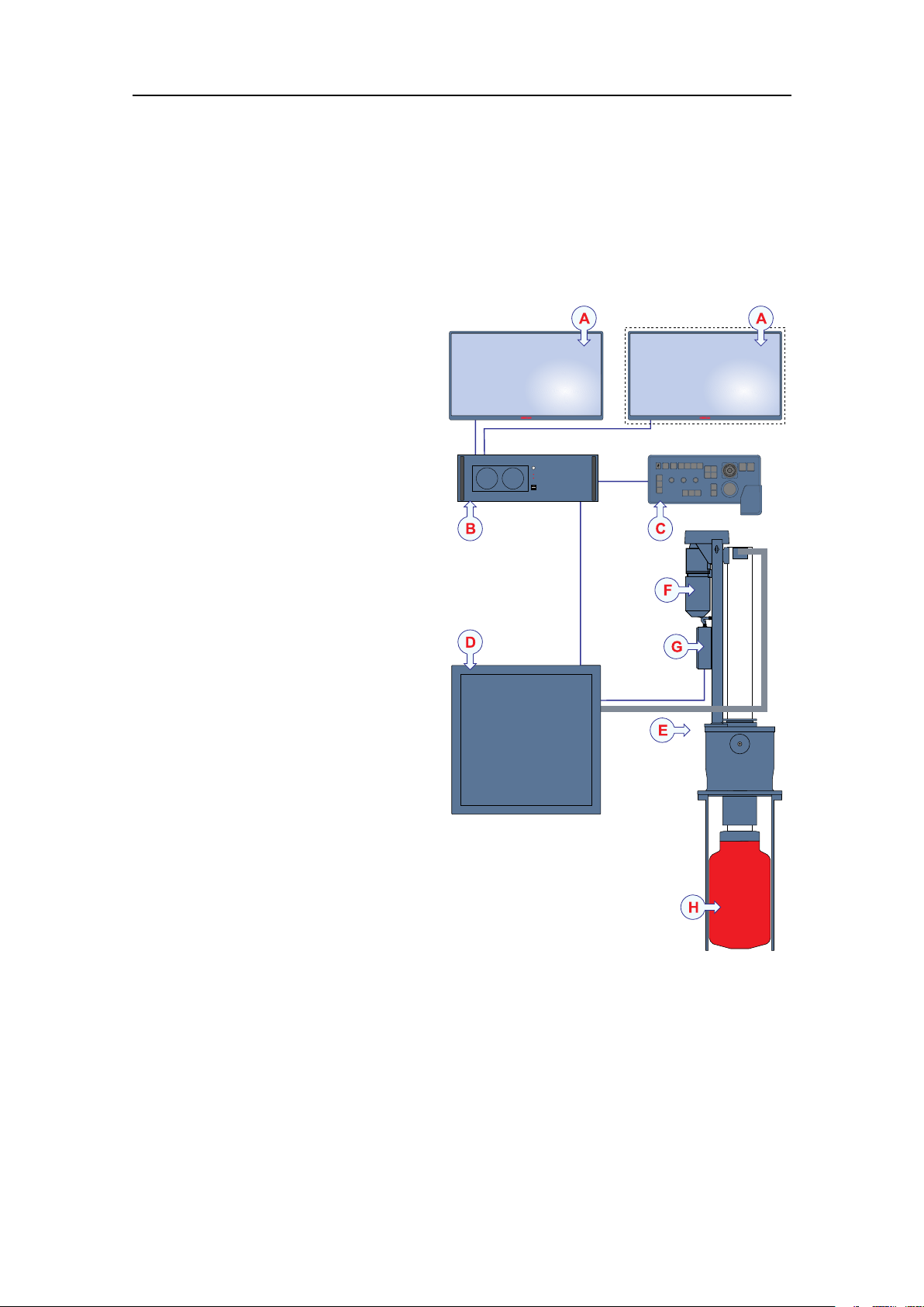
Systemdiagram
ThesystemdiagramidentiesthemaincomponentsofabasicST90system.Only
themainconnectionsbetweentheunitsareshown.Detailedinterfacecapabilitiesand
powercablesarenotshown.
ADisplay(Theseconddisplayis
optional.)
BProcessorUnit
COperatingPanel
DTransceiverUnit
EHullUnit
FHoistmotor
GMotorControlUnit
HTransducer
Inthispublication,thecomputeris
referredtoastheProcessorUnit.
Unlessotherwisespeciedina
contract,thedisplayisnotincluded
inthestandarddeliveryfromSimrad.
Thisisacommercialitemthatcan
bepurchasedlocally.
Achoiceofhullunitsisavailable
fortheST90Fishndingsonar.The
hullunitsofferdifferentlowering
depthsandcablelengths.Thesame
transducerisusedonallhullunit
types.Thesameinstallationtrunk
isusedonallhullunittypes.
Relatedtopics
Systemdescription,page19
Systemunits,page23
22
442703/B
Page 25

Systemunits
Topics
Displaydescription,page23
ProcessorUnitdescription,page23
TransceiverUnitdescription,page24
OperatingPaneldescription,page26
Hullunitdescription,page27
Transducerdescription,page29
Installationtrunkdescription,page30
SimradST90
Displaydescription
AdisplayisarequiredpartoftheST90Fishndingsonar.Forbestreadability,the
displaymustbeprotectedfromglareandhavethecorrectheightandangle.
AnycommercialdisplaycanbeusedwiththeST90Fishndingsonar,providedthatthe
displaymeetstheminimumrequirements.
ThedisplayisnotastandardpartoftheST90delivery.Thisisacommercialitemthat
canbepurchasedlocally.KongsbergMaritimemayprovideasuitabledisplay.
Thechosendisplaymustbedesignedformaritimeuse,anditmustmeettheminimum
performancespecications.Youmustalsomakesurethatthechosendisplaysupports
thevideoformatsprovidedbytheProcessorUnit.
Relatedtopics
Systemunits,page23
Scopeofsupply,page32
ProcessorUnitdescription
TheST90ProcessorUnitisaruggedandpowerfulcomputer.Itisdesignedforlonglife
inademandingmaritimeenvironment.TheProcessorUnitcontainstheoperational
software,andofferstheuserinterfacethatallowsyoutocontroltheST90.Furthermore,
itoffersanumberofserialandEthernetlinesforcommunicationwithexternaldevices.
Adedicatedmaritimecomputerisprovidedwith
theST90Fishndingsonar.Inthispublication,the
computerisreferredtoastheProcessorUnit.Itisset
upwithallnecessarysoftware.TheProcessorUnitis
normallymountedonthebridge.
442703/B
23
Page 26
SimradST90InstallationManual
TheProcessorUnitisdesignedforruggedmaritimeuse.Ithasbeencustomizedby
KongsbergMaritime.Exceptfromthefans,itcontainsnomovingparts.Thecomputer
isbasedonacommercialdesign,butthesoftwareandhardwarehavebeenspecied
byKongsbergMaritimetosuittheST90requirements.TheProcessorUnitcabinetis
placedonshockabsorbers.
TheProcessorUnitisbasedontheMicrosoft
®
Windows®10operatingsystem.
ThecomputeroffersmultipleUSBportsforusewithfuturesoftwareupgrades.These
USBportsalsoallowyoutoexportscreencapturesfromtheST90.
Note
TheoperatingsystemhasbeenmodiedtomakethecomputerworkwiththeST90.
ThesemodicationsincluderemovalofallsafetyfeaturesprovidedbyMicrosoft
®
built-inrewallandallvirusprotectionfeatureshavebeenremoved.Anyattemptto
usethecomputerforanyotherpurposesthanST90operation,suchasgames,desktop
applicationsandInternetconnection,mayresultinseriousdamagetotheprogram.Such
damagesarenotcoveredbythewarranty.
Relatedtopics
Systemunits,page23
Scopeofsupply,page32
InstallingtheEnixProcessorUnit,page148
Technicalspecications,page388
385609ProcessorUnitdimensions,page409
.The
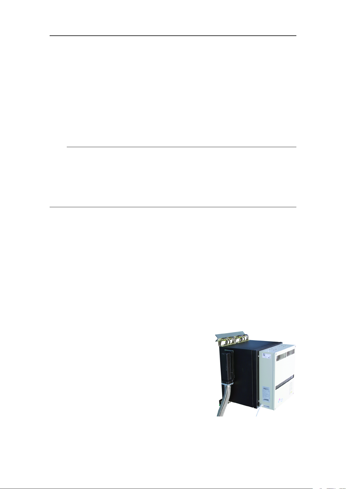
TransceiverUnitdescription
TheST90TransceiverUnitisprovidedtotransmitacousticenergythroughwater.This
transmissionandreceptionarecommonlyreferredtoasaping.Aftereachtransmission,
thetransceiverreceivestheechoesfromthetargetsinthewaterand/ortheseabed.These
echoesarelteredandampliedandthenconvertedintodigitalformat.
TheST90TransceiverUnitisnormallylocatedin
thesonarroom.Itismountedonthebulkheadusing
powerfulshockabsorbers.Thephysicaldistanceto
thehullunitislimitedbythelengthofthetransducer
cables.
TheTransceiverUnitcontrolsthetransmissionand
receptionmadebythe384transmittersand384
receiverchannels.12identicaltransceiverboards
areused.TheTransceiverUnitalsoholdsanEthernet
switchandalargecapacitorbank.Aninternalpower
supplyisprovidedtosupplytherequiredDCvoltages
totheTransceiverUnit.
24
442703/B
Page 27

SimradST90
TwohighcapacityEthernetcablesconnecttheProcessorUnittotheTransceiverUnit.
AnotherhighqualityEthernetcableisusedtoconnecttheTransceiverUnittotheMotor
ControlUnitonthehullunit.Itisveryimportantthathigh-qualityEthernetcablesare
used.Y oumustuseCA T-5ESTP(ShieldedTwistedPair)qualityorbetter.Ifyouuse
cableswithlowerbandwidthcapacityyouwillreducetheST90performance.Donot
connecttheProcessorUnittotheTransceiverUnitusinganexistinglocalareanetwork
(LAN).
Tip
WestronglyrecommendthatminimumthreeEthernetcablesareinstalledbetweenthe
sonarroomandthebridge.Twocablesareforoperationaluse,whiletheothersare
spare.
Thetransducercablesarepluggedintothesidewallofthetransceivercabinetusinga
specialconnector.Theconnectorsforpowerandinterfacesarelocatedatthebottom
ofthecabinet.
Note
ToextendthelifetimeoftheST90TransceiverUnit,itmustbemountedatdryandclean
locationwithsufcientventilation.Observethesonarroomrequirements
TheTransceiverUnitisttedwithacommercialheatexchanger.Thepurposeoftheheat
exchangeristoprovideastable,cleanandtemperaturecontrolledenvironmentforthe
electroniccircuitryinsidetheTransceiverUnit.Theheatexchangeralsoinhibitsdust
anddirtparticlesfromenteringtheTransceiverUnit.Theheatexchangerispowered
from230VACusingaseparateoutlet.
Relatedtopics
Systemunits,page23
Scopeofsupply,page32
InstallingtheTransceiverUnit,page153
Technicalspecications,page388
381457T ransceiverUnitdimensions,page421
442703/B
25
Page 28

SimradST90InstallationManual
OperatingPaneldescription
TheOperatingPaneloffersallnecessarycontrolfunctionsfornormaloperationofthe
ST90.
ThecontrolsprovidedbytheOperatingPanelare
arrangedinlogicalfunctionalgroups.Thisoffers
youclearandeasyoperationwithfastaccesstokey
functionality.ThemajorityoftheST90functionscan
beaccessedusingthetrackballontheOperatingPanel
andthemenusystemshownintheST90presentation.
Tip
YoucanalsouseastandardcomputermousetocontroltheST90.Themousecanbe
connectedtoeithertheOperatingPanelordirectlytotheProcessorUnit.
AdedicatedEthernetcableisusedtoconnecttheOperatingPaneltotheProcessorUnit.
TheOperatingPanelisprovidedwithabuilt-inpowersupply .Themainsvoltageforthe
OperatingPanelis115or230V AC,anditwillautomaticallysensethesupplyvoltage.
Note
TheST90supportstwodifferentoperatingpanels.Thesearereferredtoas"Mk1"and
"Mk2".
AsecondaryOperatingPanelmaybeconnectedtotheST90ProcessorUnit.Thismay
beusefulinconjunctionwithaseconddisplayifyouwishtocontroltheST90fromtwo
differentlocationsonyourvessel.
Relatedtopics
Systemunits,page23
Scopeofsupply,page32
InstallingtheOperatingPanel(Mk2),page151
Technicalspecications,page388
SettinguptheOperatingPanel(Mk2),page278
UsingasingleOperatingPaneltocontrolmorethanonesonar(Mk2),page320
UsingmorethanoneOperatingPaneltocontrolthesonar(Mk2),page324
204688OperatingPaneldimensions(Mk1),page413
440698OperatingPanelcut-outdrawing(Mk2),page415
443179OperatingPaneldimensions(Mk2),page416
439594OperatingPaneladapterplate(Mk2),page419
26
442703/B
Page 29

SimradST90
Hullunitdescription
ThehullunitprovidedwiththeST90isdesignedtolowerthetransducerdownbelowthe
ship’shullwhentheST90shallbeused.WhentheST90isswitchedoff,thetransducer
ishoistedforprotection.
TheST90Fishndingsonarcanbeprovidedwithoneofthefollowinghullunits.
HullUnit
Outlinedimensionsdrawings:
-ST92:447567
-ST93:435546
-ST94:447545
Partnumber
4414864.6m ST92
441488
4385204.6m ST93
441490
4414924.6m ST94
441494
Loweringdepth
1.2m
1.6m
2.1m
Transducercable
7m
7m
7m
Maximumspeed
21knots
16knots
11knots
Thesametransducerisusedonallhullunittypes.Thesameinstallationtrunkisusedon
allhullunittypes.
Note
OntheST94HullUnit,thetransducerisautomaticallyhoistedto1.6metreswhenvessel
speedexceeds1 1knots.
Thehullunitisalargemechanicalconstruction.Itismountedonthetopofthe
installationtrunk.Theinstallationtrunkpenetratestheship’shull,andallowsthe
transducertobeloweredintothesea.Thehullunitisnormallylocatedintheforward
partofthevessel.Thislocationisrecommendedtoavoidthenoisefromthepropellers
andtheengine.
ThepurposeoftheMotorControlUnitistocontrolthehoistingmotoronthehullunit.
WhenyoumaketheappropriatecommandsontheST90sonar,theMotorControlUnit
willstartandstopthemotor.Itwillalsomakesurethatthemotorrotatesthecorrectway.
Themotionsensorforthebuilt-inelectronicstabilizationofthesonarbeamsisprovided.
•Tolowerthetransducer,pressDownontheOperatingPanel.Toindicatetransducer
movement,theDownindicatorlampashes,andanaudiblesignalissounded.When
thebottompositionhasbeenreached,theindicatorlampislit,andtheaudiblesignal
stops.
•Toretractthetransducer,pressUpontheOperatingPanel.
Thetransducercanalsobeloweredtoanyselectedmiddleposition.OntheOperating
Panel,pressMiddle.Incaseofpowerfailure,thetransducercanberaisedorlowered
manuallybymeansofahandcrank.
442703/B
27
Page 30

SimradST90InstallationManual
Note
IfyouforgettohoistthetransducerbeforetheST90isswitchedoff,thetransduceris
hoistedautomaticallybeforethepowerisdisconnected.Thetransducerisalsohoisted
automaticallyifaseriousmalfunctionoccurstothecommunicationbetweenthebridge
andthehullunit.
Caution
Ifthetransducerhitslargerobjectsorbottom,thetransducershaftmaybebent,or
-inworstcase-itcanbebrokenoff.Abrokentransducershaftwillcausewater
leakagethroughthetopoftheshaft.Ifyoususpectthatthetransducershaftisseriously
damagedwithholes,donot
Topreventseriousdamagetothevesselorthevesselstability,youmusthaveawater
pumpandawarningsysteminthesonarroom.
retractthetransducertoitsupperposition.
Relatedtopics
Systemunits,page23
Scopeofsupply,page32
Installingthehullunit,page124
HullUnitpowerrequirements,page394
ST92HullUnitweightandoutlinedimensions,page398
ST93HullUnitweightandoutlinedimensions,page398
ST94HullUnitweightandoutlinedimensions,page399
HullUnitenvironmentalrequirements,page401
HullUnitcompasssafedistance,page404
447567HullUnitdimensionsST92,page425
435546HullUnitdimensionsST93,page428
447545HullUnitdimensionsST94,page431
Settingtoworksummary,page242
Startingupthehullunit,page257
Hullunitdescription,page27
Hullunitfamiliarization,page133
MotorControlUnitfamiliarization,page261
InitialsafetycheckoftheMotorControlUnit,page262
Checkingthehostingmotor’s3-phaseACconnections,page263
Connectingthe3-phaseACpowertotheMotorControlUnit,page265
Ventingthetransducershaftsleeve,page266
Checkingthe3-phaseconnectionforcorrectrotation,page268
CheckingtheoperationoftheHoistingandLoweringcontactors,page270
Checkingthetransducerloweringandhoistingfunctionality,page273
28
442703/B
Page 31

SimradST90
Transducerdescription
ThecylindricalST90transducerallowsthesonarbeamtoprovideafull360degrees
coverageofthewatervolume.
ALowerpartofshaftsleeve
BLowerpartoftransducershaft
CTransducerwithitsredprotectivecoating
Thetransducerconvertstheelectricenergygeneratedbythe
TransceiverUnittophysicalvibrations.Thesevibrationsalter
thewaterpressure,andcreateanacousticpulsethatissentinto
thewater.Theacousticsignalistransmittedasabeam.The
durationoftheacousticpulse,aswellasitsfrequencyand
shape,arecontrolledbytheTransceiverUnit.Thedirection
andopeningangleofthebeamiscontrolledbytheTransceiver
Unitandthephysicalpropertiesofthetransducer.After
thetransmission,thetransducerworksasa"microphone".It
convertsthewaterpressurecreatedbytheacousticechoesto
electricenergy.TheseweakechosignalsaresenttotheampliersintheTransceiverUnit.
Thetransducerislargeandheavy.Itcontains384individualelements.
Thetransducerismountedatthebottomendofthehullunit’stransducershaft.This
allowsthetransducertobeloweredintothewaterforoperationaluse,andretractedfor
protectionwhentheST90isturnedoff.Byloweringthetransducerintothewater,you
mayalsobeabletoreducethenoisecreatedbythelaminarowofwateralongthehull.
Note
Theredprotectivecoatingisanvitalpartofthetransducer.Itisveryimportantthat
neitherthiscoatingnortheinternalpartsofthetransduceraredamagedduringthe
handling,installationorcleaning.Anyholesand/orscratchesinthetransducersurface
willallowwatertopenetratethetransducer.Ifaleakoccurs,thetransducermustbe
replaced.
Rulesfortransducerhandling
Atransducermustalwaysbehandledasadelicateinstrument.Incorrectactionsmay
damagethetransducerbeyondrepair.Aphysicalblowtothetransducerfacemayeasily
damageoneormoreelements.Observethesetransducerhandlingrules:
•Donotactivatethetransducerwhenitisoutofthewater.
•Donothandlethetransducerroughlyandavoidimpacts.
•Donotexposethetransducertodirectsunlightorexcessiveheat.
•Donotdamagetheouterprotectiveskinofthetransducer.
•Donotusehigh-pressurewater,sandblasting,metaltoolsorstrongsolventstoclean
thetransducer.
442703/B
29
Page 32

SimradST90InstallationManual
•Donotsteponthetransducercables.
•Donotdamagethetransducercables,andavoidexposuretosharpobjects.
Relatedtopics
Systemunits,page23
Scopeofsupply,page32
Installingthehullunit,page124
HullUnitpowerrequirements,page394
ST92HullUnitweightandoutlinedimensions,page398
ST93HullUnitweightandoutlinedimensions,page398
ST94HullUnitweightandoutlinedimensions,page399
HullUnitenvironmentalrequirements,page401
HullUnitcompasssafedistance,page404
447567HullUnitdimensionsST92,page425
435546HullUnitdimensionsST93,page428
447545HullUnitdimensionsST94,page431
Installationtrunkdescription
Theinstallationtrunkprovidesthephysicalfoundationfortheentirehullunit.The
installationtrunkpenetratesthehull.Itisthereforeacrucialpartofthehullunit
assembly.InordertoensureproperST90operation,thephysicallocationofthe
installationtrunkmustbecarefullyselected.
Note
Theinstallationtrunkisnotincludedinthestandarddelivery.
Theinstallationtrunkisnotusedwhenagatevalveismounted.Theinstallationtrunkis
replacedwithatransducerdock.
Theinstallationtrunkmaybefabricatedbytheshipyard,orsuppliedbyKongsberg
Maritimeasanoption.Thedrawingsoftheinstallationtrunkandtheblindangeare
includedinthismanual.
Theinstallationtrunk-withablindange-canbeorderedfromKongsbergMaritimeas
anoptionaldelivery.Asanalternative,theinstallationtrunkcanbemanufacturedbythe
shipyardbasedonthedrawingsinthismanual.Alocallymanufacturedinstallationtrunk
canbeadjustedtobettertthepropertiesofthevessel’shull.
Note
Iftheinstallationtrunkismanufacturedlocally,theinstallationshipyardisresponsible
forobtainingtheapprovalcerticatesfromtherelevantnationalregistry.
30
442703/B
Page 33

Relatedtopics
Systemunits,page23
Scopeofsupply,page32
Mountingtheinstallationtrunk,page109
436691Installationtrunkdimensions,page435
207485Blindangedimensions(ø760mm),page438
SimradST90
442703/B
31
Page 34

SimradST90InstallationManual
Scopeofsupply
Topics
Basicitemsprovidedwithastandarddelivery,page32
Additionalrequireditems,page35
Additionaloptionalitems,page39
Basicitemsprovidedwithastandarddelivery
ToassembleacompleteST90system,youwillneedasetofsystemunits.Themain
unitsrequiredareprovidedwiththestandarddelivery.Otherrequiredunitsmaybe
purchasedfromKongsbergMaritimeorobtainedlocally.Someunitsareoptional.
WhenyouunpackthepartsprovidedwiththeST90delivery,makesurethatthecorrect
itemsareincluded.
Basicitems
ItemPartnumberInthebox
TransceiverUnit
ProcessorUnit
OperatingPanel(Mk1)
OperatingPanel(Mk2)
Connectioncable
TheST90supportstwodifferentoperatingpanels.Thesearereferredtoas"Mk1"and"Mk2".
441481
441484Computer
SH8-203593
442453
329512
TransceiverUnit
Powercable
Ethernetcable(10m)
Powercable
Seriallineconnectorsandadapters
DVItoVGAadapter
Documentation
Software
PhoenixContact"VariosubRJ45
Quickcon"connectorx2
OperatingPanel
Interfacecables
Mountinghardware
OperatingPanel
Ethernetcable
Mountinghardware
Ethernetcable(100m)
HullUnit
TheST90Fishndingsonarcanbeprovidedwithoneofthefollowinghullunits.The
sametransducerisusedonallhullunittypes.Thesameinstallationtrunkisusedon
allhullunittypes.
32
442703/B
Page 35

SimradST90
ItemPartnumberInthebox
HullUnitST92
HullUnitST93
HullUnitST94
EachhullunitisprovidedwithanO-ringforusebetweenthehullunitangeandthetopofthe
installationtrunk(ortransducerdock).Relevantmountinghardware(bolts,nutsandwashers)are
alsoincluded.
441486
441488
438520
441490
441492
441494
HullUnit
Transducer
Transducercable4.6m
O-ring(540-078749)
HullUnit
Transducer
Transducercable7m
O-ring(540-078749)
HullUnit
Transducer
Transducercable4.6m
O-ring(540-078749)
HullUnit
Transducer
Transducercable7m
O-ring(540-078749)
HullUnit
Transducer
Transducercable4.6m
O-ring(540-078749)
HullUnit
Transducer
Transducercable7m
O-ring(540-078749)
Operationalsoftware
Operationalsoftwareisprovidedonasuitablemedia.Theoperationalsoftwareis
installedontheProcessorUnit,andreadyforuse.
End-userdocumentation
End-userdocumentationisprovidedonpaperand/ordigitalformats.Alldocumentation
relatedtooperationandinstallationcanbedownloadedfromourwebsite.
•https://www.simrad.com/st90
Relatedtopics
Scopeofsupply,page32
Installingthehullunit,page124
HullUnitpowerrequirements,page394
ST92HullUnitweightandoutlinedimensions,page398
ST93HullUnitweightandoutlinedimensions,page398
ST94HullUnitweightandoutlinedimensions,page399
HullUnitenvironmentalrequirements,page401
HullUnitcompasssafedistance,page404
447567HullUnitdimensionsST92,page425
442703/B
33
Page 36

SimradST90InstallationManual
435546HullUnitdimensionsST93,page428
447545HullUnitdimensionsST94,page431
34
442703/B
Page 37

SimradST90
Additionalrequireditems
AdditionalitemsareavailablefortheST90.SomearerequiredforST90operation.
TheseitemsmustbeaddedtotheST90forfulloperationalfunctionality.Theadditional
itemscanbeprovidedbyKongsbergMaritime.Youcanorderthemwiththeotherbasic
ST90items.Y oucanalsopurchasetheseitemsfromyourdealer,agentorlocalsupplier.
Topics
Installationtrunk,page35
Display,page36
UninterruptiblePowerSupply(UPS),page37
Speedlog,page37
Coursegyro,page38
Installationtrunk
Aninstallationtrunkisrequiredforhullunitinstallation.Theinstallationtrunkisnot
includedinthestandarddelivery.
Theinstallationtrunkmaybefabricatedbytheshipyard,orsuppliedbyKongsberg
Maritimeasanoption.Thedrawingsoftheinstallationtrunkandtheblindangeare
includedinthismanual.
Note
IfyouarereplacinganoldersonarwithanewST90,youmaynotneedtoinstallanew
installationtrunk.Adedicatedtrunkextendercanbeprovidedtoincreasetheheightof
yourexistinginstallationtrunk.
ItemPartnumber
Installationtrunk
Trunkextender
Trunkextender
Drawing
441679436691
391397374676FromSU90
441659439413FromSX90
Inthebox
Installation
trunk
Blind
ange
207485
Rubber
gasket
toST90
Height:
180mm
toST90
Height:
350mm
TheoptionalinstallationtrunkofferedbyKongsbergMaritimeisapprovedbyDet
NorskeV eritas(DNVGL),andincludesablindangeandarubbergasket.
442703/B
35
Page 38

SimradST90InstallationManual
Note
Iftheinstallationtrunkismanufacturedlocally,theinstallationshipyardisresponsible
forobtainingtheapprovalcerticatesfromtherelevantnationalregistry.
Relatedtopics
Scopeofsupply,page32
Mountingtheinstallationtrunk,page109
436691Installationtrunkdimensions,page435
207485Blindangedimensions(ø760mm),page438
Display
ThedisplayisnotastandardpartoftheST90delivery.Thisisacommercialitemthat
canbepurchasedlocally.
AnycommercialdisplaycanbeusedwiththeST90Fishndingsonar,providedthat
thedisplaymeetstheminimumrequirements.Thechosendisplaymustbedesignedfor
maritimeuse,anditmustmeettheminimumperformancespecications.Y oumustalso
makesurethatthechosendisplaysupportsthevideoformatsprovidedbytheProcessor
Unit.
Wesuggestthatyoupurchasealargehigh-resolutiondisplay.
KongsbergMaritimemayprovideasuitabledisplay.
Display
HattelandJH19T14
IsicDuraMONWSMD24
IsicDuraMONMD24Glass
PartnumberInthebox
335513
339785
383050
354265
417776
419970
Display(19",1280x1024)
Powercable
Documentation
Mountinghardware
Display(24",1920x1080)
Powercable
Documentation
Mountingbracket
Display(24",1920x1080)
Powercable
Documentation
Mountingbracket
Relatedtopics
Scopeofsupply,page32
36
442703/B
Page 39

UninterruptiblePowerSupply(UPS)
ItisimportanttoensurecontinuousoperationoftheST90independentofvaryingquality
ofthevessel'smainssupply .Theuseofuninterruptiblepowersuppliesistherefore
required.
SimradST90
Uninterruptiblepowersupplyunitsarenot
includedinthestandardST90delivery .These
itemsmustbepurchasedlocally.
Severalcommercialtypesareavailable.Tochoosethebestpowersolutionforyour
ST90installation,considerenvironmentalconditions,spaceavailable,theavailability
anddurationofthebatteries,andthepowerrequirementsoftheST90.
Twosystemsarerequired:
1OnepowersystemisrequiredtopowertheProcessorUnitandthedisplay.
2OnepowersystemisrequiredtopowertheTransceiverUnit.
Theminimumrequirementsfortheuninterruptiblepowersupply(UPS)are:
•Inputvoltage:Theinputvoltagemusttvesselsupplyvoltage.
•Outputvoltage:230V AC,50Hz
•Outputpower:
–ProcessorUnit+Display:1000W
–TransceiverUnit:1500W
•Outputform:TheoutputACvoltagemustbeasinewave.
Relatedtopics
Scopeofsupply,page32
Speedlog
Inordertooperatecorrectly,theST90requiresinputfromaspeedlog.Aspeedlogis
normallynotapartoftheST90delivery.WhenaspeedlogisconnectedtotheST90,the
vessel’scurrentspeedcanbepresentedintheuserinterface.
Note
Withouttheinputfromaspeedlog,theST90willneitherbeabletopresentcorrect
navigationalinformation,norcompensateforvesselmovements.Thislackof
compensationwillpreventtheST90fromprovidingcorrectechoinformation.
Inmostcasesasuitablesensorisalreadyinstalledonthevessel.Aglobalpositioning
system(GPS)withacompatibleoutputformatcanalsobeused.
Thespeedloginterfacerequirementsare:
•Serialline:StandardNMEA0183datagramformats
•Ethernet(LAN)line:StandardNMEA0183datagramformats
442703/B
37
Page 40

SimradST90InstallationManual
Relatedtopics
Scopeofsupply,page32
Coursegyro
Inordertooperatecorrectly,theST90requiresinputfromacoursegyro.Acoursegyro
isnotapartoftheST90delivery.WhenacoursegyroisconnectedtotheST90,the
vessel’scurrentheadingcanbepresentedintheuserinterface.
Note
Withouttheinputfromacoursegyro,theST90willnotbeabletopresentcorrect
navigationalinformation.
Inmostcasesasuitablecoursegyroisalreadyinstalledonthevessel.Aglobal
positioningsystem(GPS)withacompatibleoutputformatcanalsobeused.
Thecoursegyrointerfacerequirementsare:
•Serialline:StandardNMEA0183datagramformats
•Ethernet(LAN)line:StandardNMEA0183datagramformats
Relatedtopics
Scopeofsupply,page32
38
442703/B
Page 41

SimradST90
Additionaloptionalitems
AdditionalitemsareavailablefortheST90.SomeareoptionalforST90operation.
Theseitemsmayforexamplesimplifytheinstallation,orincreasethefunctionality.Y ou
canorderthemwiththeotherbasicST90items.Y oucanalsopurchasetheseitems
fromyourdealer,agentorlocalsupplier.
Topics
Secondarydisplay,page39
SecondaryOperatingPanel,page40
Globalpositioningsystem(GPS),page41
MotionReferenceUnit(MRU),page41
Seriallinesplitter,page42
Gatevalve,page42
Extendedrange,page43
Audiosystem,page44
Secondarydisplay
Youcanuseone,twoorthreedisplaysonyourST90ProcessorUnitdependingon
personaland/oroperationalpreferences.ThedisplayisnotastandardpartoftheST90
delivery.Thisisacommercialitemthatcanbepurchasedlocally.
Tip
TheDockingViewsfunctionprovidedbytheST90allowsyoutorearrangethephysical
positionsoftheviews,andchangetheirsizes.Eachoperatingmodeispresentedwith
asetofviews.Theseareplacedatdifferentpositionswithdifferentsizes.Withthe
DockingViewsfunctionyoucanmoveandre-sizetheviewsintheST90presentation.If
youhaveseveraldisplaysconnectedtoyourProcessorUnityoucanevenmoveselected
viewstoanotherdisplay.
Forthisreasonyoumaynditusefultohavemorethanonedisplayconnectedtothe
ST90.
AnycommercialdisplaycanbeusedwiththeST90Fishndingsonar,providedthat
thedisplaymeetstheminimumrequirements.Thechosendisplaymustbedesignedfor
maritimeuse,anditmustmeettheminimumperformancespecications.Y oumustalso
makesurethatthechosendisplaysupportsthevideoformatsprovidedbytheProcessor
Unit.
442703/B
39
Page 42

SimradST90InstallationManual
Tip
IfyoualsowanttocontroltheST90fromthissecondarydisplaylocation,youcanaddan
extraOperatingPanel.
IfthedistancebetweentheProcessorUnitandyourseconddisplayisconsiderable,we
suggestthatyouuseKVM(KeyboardV ideoMouse)technologytopreservethevideo
quality.
KongsbergMaritimemayprovideasuitabledisplay.Consultyourlocaldealeroragent
formoreinformation.
Relatedtopics
Scopeofsupply,page32
SecondaryOperatingPanel
AsecondaryOperatingPanelmaybeconnectedtotheST90ProcessorUnit.Thismay
beusefulinconjunctionwithaseconddisplayifyouwishtocontroltheST90fromtwo
differentlocationsonyourvessel.
ThecontrolsprovidedbytheOperatingPanelare
arrangedinlogicalfunctionalgroups.Thisoffers
youclearandeasyoperationwithfastaccesstokey
functionality.ThemajorityoftheST90functionscan
beaccessedusingthetrackballontheOperatingPanel
andthemenusystemshownintheST90presentation.
Youcanalsouseastandardcomputermousetocontrol
theST90.ThemousecanbeconnectedtoeithertheOperatingPanelordirectlyto
theProcessorUnit.
ItemPartnumberInthebox
SecondaryOperatingPanel
(Mk2)
Tip
442453
OperatingPanel
Ethernetcable
Mountinghardware
IfthedistancebetweentheProcessorUnitandyourseconddisplayisconsiderable,we
suggestthatyouuseKVM(KeyboardV ideoMouse)technologytopreservethevideo
quality.
Relatedtopics
Scopeofsupply,page32
SettinguptheOperatingPanel(Mk2),page278
UsingasingleOperatingPaneltocontrolmorethanonesonar(Mk2),page320
UsingmorethanoneOperatingPaneltocontrolthesonar(Mk2),page324
40
442703/B
Page 43

SimradST90
Globalpositioningsystem(GPS)
Aglobalpositioningsystem(GPS)mustbeconnectedtotheST90.Whenaglobal
positioningsystem(GPS)connectedtotheST90,thevessel’scurrentgeographical
positioncanbepresentedintheuserinterface.Itwillalsoprovidelatitudeandlongitude
informationforthecursorandmarker(s).Inadditiontonavigationaldata,theglobal
positioningsystem(GPS)canalsobeusedtoprovidespeedinformation.
Note
Mostglobalpositioningsystem(GPS)canprovidecourseinformation,butthisdatais
generallytooinconsistenttoprovideastableST90presentation.
Theglobalpositioningsystem(GPS)interfacerequirementsare:
•Serialline:StandardNMEA0183datagramformats
•Ethernet(LAN)line:StandardNMEA0183datagramformats
Relatedtopics
Scopeofsupply,page32
MotionReferenceUnit(MRU)
Inordertooperatecorrectly,theST90requiresinputfromamotionreferenceunit
(MRU).Bydefault,theST90usesabuilt-inmotionsensor.Itisplacedinsidethe
MotorControlUnit.Forimprovedoperationalaccuracy,anexternalmotionreference
unit(MRU)maybeused.
Note
Withouttheinputfromamotionreferencesensor ,theST90willnotbeabletocompensate
forthevesselmovements.ThislackofcompensationwillpreventtheST90from
providingcorrectechoinformation.
TheST90hasbeendesignedtomatchthemotionreferenceunit(MRU)sensors
manufacturedbyKongsbergSeatex.Descriptionsofallavailabletypesareprovidedon
theirwebsite.
•https://www.km.kongsberg.com/seatex
Forthemotionsensorunit(MRU)tocommunicatewiththeST90,itmustsupportthe
followinginterfaceformat:
•KongsbergEMAttitude3000
TheEMAttitude3000isaproprietarydatagramformatcreatedbyKongsberg
Maritimeforusewithdigitalmotionsensors.Itholdsroll,pitch,heaveandheading
information.Thedatagramcontainsa10-bytemessage.
KongsbergMaritimemayprovideasuitablemotionreferenceunit.Consultyourlocal
dealeroragentformoreinformation.
442703/B
41
Page 44

SimradST90InstallationManual
MotionReferenceUnit(MRU)
SeatexMRU-D
PartnumberInthebox
–
MotionReferenceUnit(MRU)
Documentation
Relatedtopics
Scopeofsupply,page32
Seriallinesplitter
Onlargeinstallationswithmanyhydroacousticsystems,theseoftenrequirethesame
navigationalinformationfromasinglesensor.
Informationsuchascurrentdepthorspeedisprovidedonserialformat.Oneormore
seriallinesplitterscanbeusedtodistributetheinformationfromasinglesensorto
severaldifferentrecipients.
ItemPartnumberInthebox
Seriallinesplitter
Seriallinesplitter
337775
317156
Seriallinesplitter(Øverland
UPC-5000P)
TheØverlandUPC-5000Pserialline
splitterofferstwoseparateinputsand
fteenRS-232andRS-422outputs.
Seriallinesplitter(ØverlandUPC-3005)
TheØverlandUPC-3005serialline
splitteroffersoneinputandeight
RS-232andRS-422outputs.
Relatedtopics
Scopeofsupply,page32
Gatevalve
Onsomevessels,additionaltransducerprotectionisrequired.Oneexampleisvessels
workinginarcticconditions.Itisimportantforthemtopreventicefromdamagingthe
transducer.Agatevalvecanthenbeaddedtothehullunitinstallation.Bymeansofa
mechanicalconstructionitshutsoffthebottomoftheinstallationtrunkwhentheST90is
notused.ThegatevalveismanufacturedbyLKV alves.
Note
Theinstallationtrunknormallyusedforhullunitinstallationisnotusedwhenagate
valveismounted.Theinstallationtrunkisreplacedwithatransducerdock.
42
442703/B
Page 45

SimradST90
Gatevalve
DN500Manuallyoperatedgate
valve
DN500Hydraulicoperatedgate
valve
Mountingange
Transducerdock
Eachgatevalveisavailableinseveraldifferentversionswithdifferentcerticatesandsupplyvoltages.
Consultyourdealerformoreinformationaboutthegatevalvesavailable.
PartnumberInthebox
–
-
599–082973
427177
Gatevalve
Mountinghardware
Documentation
Gatevalve
HydraulicPowerPack
GateValveControlUnit
Mountinghardware
Documentation
Mountingange(forgatevalveDN500)
Transducerdock
Note
Thegatevalveisplacedatthebottomofthetransducerdock.Itwillthenincreasethe
totalheightofthehullunitinstallation.
•Thehullunitlowersthetransducerdowntoaspecieddepthbelowtheship’ shull.
Thisdepthisdecreasedwiththephysicalheightofthegatevalve.Itisfurther
decreasedwiththeheightofthemountingange.
•TheST90allowsyoutodeneamiddlepositionforthetransducer .Whenyoudene
themiddleposition,youmusttakethetotalheightofthegatevalveandthemounting
angeintoconsideration.
TheST94HullUnitlowersthetransducerto2.1metresbelowthehull.Thishullunit
isabetterchoiceifagatevalveisused.
TechnicalinformationaboutthisunitisnotincludedinthisST90InstallationManual.
Refertotherelevantend-userdocumentationprovidedbythemanufacturer.
Relatedtopics
Scopeofsupply,page32
InstallingtheoptionalgatevalveDN500,page85
082973MountingangeDN500,page446
083045GatevalveinstallationDN500,page449
33498GatevalvedimensionsDN500,page451
37357GatevalvedimensionsDN500,page454
Extendedrange
TheST90canbesetupforextendedoperationalrange.
Duetointernationalregulations,sonarswithanoperationalrangeexceeding5000meters
cannotbeexportedtocertaincountrieswithoutanexportlicense.Forthisreasonthe
maximumrangeontheST90hasbeenlimitedto4500meters.Ifanexportlicenceis
obtained,therangeontheST90canbeextendedtoitsmaximumcapacity.
442703/B
43
Page 46

SimradST90InstallationManual
ItemPartnumberInthebox
Extendedrange
Note
446549
Software
Eventhoughyoucanchoosealargerangevalue,thatdoesnotmeanthatyoucandetect
yourtargetsonthesamerange.Therangevalueonlydenestherangethatisshownin
theviews.Actualtargetdetectionwillalwaysdependontheoperationalenvironment,
suchaswatertemperature,salinity,interferenceandlayersinthewatercolumn.
Relatedtopics
Scopeofsupply,page32
Audiosystem
TheaudiooutputprovidedbytheST90addssoundtotheuserexperience.Many
experiencedusersndtheaudioinformationveryuseful.Theyclaimthattheaudio
informationincreasestheefciencyoftheST90.Atrainedeareasilydetectsechoes
bythewaytheysound.
Touseaudio,youmustconnectanamplierwithloudspeakerstotheaudiooutputonthe
ProcessorUnit.Y oucanuseanamplierwithaheadset,oracommercialPCspeaker
system.Theaudiosystemmustbeprovidedwithaseparatevolumecontrol.
Thenecessaryaudiocomponentsmustbepurchasedlocally.
Abouttheaudiooutput
TheaudiooutputontheProcessorUnitisalineoutput.Nopoweramplierisprovided
tocreatesound.
Theaudiooutputmustthereforebeconnectedtoapoweredaudiosystem.Theaudio
systemmustbeprovidedwithaseparatevolumecontrol.TheMutebuttononthe
OperatingPanelenablesordisablestheaudiooutput.Itdoesnotprovidevolumecontrol.
Note
Donotconnectaloudspeakerdirectlytotheaudiooutput.Thismaydamagetheaudio
outputcircuitry.
Werecommendthatoneofthefollowingoptionsisusedforaudio.
•CommercialpoweredloudspeakersforPCuse.
•Commercialstereosystemwithamplierandtwo(ormore)loudspeakers.
•Headphonesforuseonanyoftheampliersystems.
44
442703/B
Page 47

SimradST90
Poweredloudspeakers
Wesuggestthatyouchooseaspeakersystemthatsupportsavolumecontrolandan
outputforheadphones.
AcommercialpoweredspeakersystemforPCusecanbeobtainedfromalmostanykind
ofshopforelectricappliances,homestereoorcomputers.Thereisnoneedtoinstall
alargebassspeaker.Thenumberofspeakers,sizeandpoweroutputcanbeselected
tosuitthecrewpreferences.Thelocationofthespeakersmustbedecidedtoallowfor
easyadjustmentoftheaudiolevel.
Stereosystem
Ifastereosystemisalreadyinstalledonthebridge,theaudiooutputfromtheST90can
beconnectedtoanauxiliaryinput.Theadvantageofthissetupisthatmoststereosystems
areprovidedwitharemotecontrol,andthisallowsforeasyadjustmentoftheaudiolevel.
Relatedtopics
Scopeofsupply,page32
442703/B
45
Page 48

SimradST90InstallationManual
Generalsafetyrules
Safetyisimportant.Thesafetyprecautionsmustbefollowedatalltimesduring
installationandmaintenancework.
WARNING
TheST90operateson1 15VACand/or230VACat50/60Hz.Thisvoltageislethal!
Youmustneverworkaloneonhigh-voltageequipment!
Thehullunitispoweredbya3-phasehighvoltage.
Thisequipmentmustbeservicedonlybyqualiedpersonnelfamiliarwiththe
constructionandoperationoftheST90,aswellasthepotentialhazardsinvolved.
Failuretoobservethisprecautioncouldresultinbodilyinjury.
1Youmustalwaysswitchoffallpowerbeforeinstallationormaintenanceworkon
theST90system.
Usethemaincircuitbreaker,andlabelthebreakerwithawarningsignthatinforms
othersthatmaintenanceorinstallationworkisinprogressonthesystem.
2Forsafetyreasons,twopersonsmustalwaysbepresentduringtroubleshooting
withpowerON.
3Readandunderstandtheapplicablerstaidinstructionsrelatedtoelectricshock.
4Whenevermaintenanceisinprogress,itisessentialthatarstaidkitisavailable,
andthatallpersonnelarefamiliarwiththerstaidinstructionsforelectricalshock.
5Thevariouspartsofthesystemmaybeheavy.
Makesurethattheappropriatetoolsandcertiedliftingequipmentareavailable.
Thepersonnelmustbetrainedinrelevantinstallationandmaintenancework.
Relatedtopics
Installationrequirements,page47
46
442703/B
Page 49

Installationrequirements
Topics
Supplypowerrequirements,page47
UninterruptiblePowerSupply(UPS)requirements,page47
Cablesandwiringrequirements,page48
Compassdeviationrequirements,page48
Noisesources,page49
Drydockingrequirements,page49
Requirementforclassicationapproval,page49
SimradST90
Supplypowerrequirements
Observethegeneralrequirementsrelatedtothesupplypower.
ThesupplyvoltagetotheST90mustbekeptwithin±10%oftheinstallation’snominal
voltage.
Maximumtransientvoltagevariationsonthemainswitchboard’sbus-barsarenotto
exceed-15%to+20%ofthenominalvoltage(exceptunderfaultconditions).
Relatedtopics
Installationrequirements,page47
UninterruptiblePowerSupply(UPS)requirements
ObservetheserequirementsrelatedtotheUninterruptiblePowerSupply(UPS).
ItisimportanttoensurecontinuousoperationoftheST90independentofvaryingquality
ofthevessel'smainssupply .Theuseofuninterruptiblepowersuppliesistherefore
required.
Uninterruptiblepowersupplyunitsarenot
itemsmustbepurchasedlocally.
includedinthestandardST90delivery .These
Severalcommercialtypesareavailable.Tochoosethebestpowersolutionforyour
ST90installation,considerenvironmentalconditions,spaceavailable,theavailability
anddurationofthebatteries,andthepowerrequirementsoftheST90.
Twosystemsarerequired:
1OnepowersystemisrequiredtopowertheProcessorUnitandthedisplay.
2OnepowersystemisrequiredtopowertheTransceiverUnit.
442703/B
47
Page 50

SimradST90InstallationManual
Theminimumrequirementsfortheuninterruptiblepowersupply(UPS)are:
•Inputvoltage:Theinputvoltagemusttvesselsupplyvoltage.
•Outputvoltage:230V AC,50Hz
•Outputpower:
–ProcessorUnit+Display:1000W
–TransceiverUnit:1500W
•Outputform:TheoutputACvoltagemustbeasinewave.
Relatedtopics
Installationrequirements,page47
Cablesandwiringrequirements
CorrectwiringiscrucialfortheoperationalperformanceoftheST90.
Allcablesrunningbetweensystemcabinetslocatedindifferentroomsand/orondifferent
decksmustbesupportedandprotectedalongtheirentirelengthsusingconduitsand/or
cabletrays.Notethatthecablesmustnotbeinstalledinthevicinityofhigh-power
suppliesandcables,antennacablesorotherpossiblesourcesofinterference.
Formoredetailedinformationaboutcablesandwiring,refertothebasiccable
requirements.
Relatedtopics
Installationrequirements,page47
Compassdeviationrequirements
ST90unitsthatareinstalledonthebridgemayhaveaneffectonthecompass.
Oncetheinstallationiscomplete,thevesselmustbeswungwiththeST90inboth
operativeandinoperativemodes.
Theshipownerandcaptainareresponsibleforupdatingthecompassdeviationtable
accordinglywithregardtothevessel’snationalregistryandcorrespondingmaritime
authority.
Relatedtopics
Installationrequirements,page47
48
442703/B
Page 51

Noisesources
TheoperationalperformanceoftheST90Fishndingsonardependsonthenoise
conditions.Itisessentialthatthenoisesignatureisaslowaspossible.
Thevessel’shull,rudder(s)andpropeller(s)mustbethoroughlyinspectedindrydock
priortoinstallation.
Roughnessbelowthewater-linedeformitiesintheshellplatingandprotrudingobstacles
cancreateunderwaternoise.Thesesourcesofturbulencemustbesmoothedorremoved
asbestaspossible.
Note
Itisespeciallyimportantthatthepropeller(s)arenotpittedordamaged.
Relatedtopics
Installationrequirements,page47
SimradST90
Drydockingrequirements
Wheneverahullunitandaninstallationtrunkaremountedunderthevessel’shull,
specialconsiderationsmustbemadepriortodrydocking.
MakesurethatampleclearanceundertheST90installationtrunkand/orblisteris
providedwhenyouareplacingthevesselindrydock.A voidlocatingsupportingblocks
orstructuresinthevicinityoftheST90installationtrunk.
Priortodrydocking,powerdowntheST90.Disengagethecircuitbreakerifnecessary .
LabeltheProcessorUnitand/orthecircuitbreakerclearlytopreventanyonefrom
poweringuptheST90accidentally.
Note
ThelocationoftheST90installationtrunkmustbenotedonthevessel’ sdockingplan
forfuturereference.
Relatedtopics
Installationrequirements,page47
Requirementforclassicationapproval
ClassicationapprovalisrequiredfortheST90installation.
TheST90sonartrunkinstallationmustbeapprovedbyDNVGLoranothernational
classicationsociety.Theshipownerandshipyardperformingtheinstallationare
responsibleforobtainingtheclassicationapproval.
442703/B
49
Page 52

SimradST90InstallationManual
Relatedtopics
Installationrequirements,page47
Networksecurity
IfaST90systemisconnectedtoalocalareanetwork,datasecurityisimportant.
EquipmentmanufacturedbyKongsbergMaritimeisfrequentlyconnectedtothevessel's
localareanetwork(LAN).Whenyouconnectacomputertoalocalareanetworkyou
willalwaysexposethedataonthatcomputer.Allothercomputersconnectedtothesame
networkmaybeabletoaccessyourdata.Severalthreatsmayimmediatelyoccur:
•Remotecomputerscanreadthedata.
•Remotecomputerscanchangethedata.
•Remotecomputerscanchangethebehaviourofthecomputer,forexampleby
installingunwantedsoftware.
Usually,twoparametersareusedtodenethethreatlevel:
1Thelikelihoodthatanyremotecomputerwilldoanyoftheabove.
2Thedamagedoneifaremotecomputersucceedsdoingthis.
KongsbergMaritimehasnoinformationregardingthecompletesysteminstallationon
anyvessel.SystemsprovidedbyKongsbergMaritimeareregardedasstand-aloneofine
systems.Theyarestand-aloneeventhoughtheymaybeconnectedtoanetworkfor
sensorinterfacesand/ordatadistribution.
Note
NonetworksafetyapplicationsareinstalledonKongsbergMaritimecomputers.The
computersarethereforenotprotectedagainstviruses,malwareorunintentionalaccess
byexternalusers.
SecuringtheST90systemitselfhasnomeaningunlessthereisapolicyinplacethat
securesallcomputersinthenetwork.Thispolicymustincludephysicalaccessbytrained
andtrustedusers.Thecustomer/enduseroftheST90systemwillalwaysbeincharge
ofdeningandimplementingasecuritypolicy,andprovidingtherelevantnetwork
securityapplications.
Note
KongsbergMaritimewillnotacceptanyresponsibilityforerrorsand/ordamagescaused
byunauthorizeduseoforaccesstotheST90.
50
442703/B
Page 53

SimradST90
Supportinformation
IfyouneedtechnicalsupportforyourSimradST90youmustcontactyourlocaldealer,
oroneofoursupportdepartments.Alistofallourofcesanddealersisprovidedonour
website.Y oucanalsocontactourmainsupportofceinNorway.
Norway(mainofce)
•Companyname:KongsbergMaritimeAS/Simrad
•Address:Strandpromenaden50,N-3190Horten,Norway
•Telephone:+4733034000
•Telefax:+4733042987
•Website:https://www.simrad.no
•E-mailaddress:simrad.support@simrad.com
Spain
•Companyname:SimradSpainS.L.U
•Address:PartidaAtalayes20,03570Villajoyosa,Spain
•Telephone:+34966810149
•Telefax:+34966852304
•Website:http://www.simrad.es
•E-mailaddress:simrad.spain@simrad.com
France
•Companyname:SimradFrance
•Address:5ruedeMenMeur,29730Guilvinec,France
•Telephone:+33298582388
•Telefax:+33298582388
•Website:http://www.simrad.fr
•E-mailaddress:simrad.france@simrad.com
USA
•Companyname:KongsbergUnderwaterTechnologyInc/SimradFisheries
•Address:1921033rdAveW,SuiteB,Lynnwood,WA98036,USA
•Telephone:+14257121136
•Telefax:+14257121193
•Website:https://www.simrad.com
•E-mailaddress:sh.usa.support@simrad.com
442703/B
51
Page 54

SimradST90InstallationManual
Canada
•Companyname:KongsbergMesotechLtd.
•Address:1598KebetWay,PortCoquitlam,BC,V3C5M5,Canada
•Telephone:+16044648144
•Telefax:+16049415423
•Website:https://www.simrad.com
•E-mailaddress:simrad.canada@simrad.com
Malaysia
•Companyname:KongsbergMaritimeMalaysiaSdn.Bhd
•Address:Unit27-5SignatureOfces,TheBoulevard,MidV alleyCity,Lingkaran
SyedPutra,59200KualaLumpur,Malaysia
•Telephone:+6564117488
•Telefax:+60322013359
•Website:https://www.simrad.com
•E-mailaddress:simrad.asia@simrad.com
Korea
•Companyname:KongsbergMaritimeKoreaLtd
•Address:#1101-HarborT ower,113-1,Nampodong6-Ga,Jung-Gu,Busan600-046
Korea
•Telephone:+82-51-242-9933
•Telefax:+82-51-242-9934
•Website:https://www.simrad.com
•E-mailaddress:simrad.korea@simrad.com
China
•Companyname:KongsbergMaritimeChinaLtd
•Address:555ChuanqiaoRoad,China(Shanghai)PilotFreeTradeZone,201206,
China
•Telephone:+86-21-3127-9888
•Telefax:+86-21-3127-9555
•Website:https://www.simrad.com
•E-mailaddress:simrad.china@simrad.com
52
442703/B
Page 55

Topics
Installationsummary,page54
Aboutinstallationdrawings,page57
Preparations
Preparations
Tools,equipmentandconsumablesrequiredforST90installation,page57
Personnelqualications,page58
Choosingthebestlocationforthehullunit,page59
Locationofhardwareunitsonthebridge,page62
Sonarroomrequirements,page66
Acousticnoise,page76
442703/B
53
Page 56

SimradST90InstallationManual
Installationsummary
InstallationoftheST90isademandingtaskthatrequirescarefulpreparations,anumber
ofspecicprocedures,wiringandrequiredsystemsettings.
Context
Anoverallinstallationprocedureisprovided.Thisproceduredoesnotdescribeany
detailedtasks.Refertotherelevanttasksinthismanual.
Note
InordertoobtainmaximumsafetyandST90performance,itisveryimportantthatthe
installationproceduresinthismanualarecompliedto.Youmustdothetasksintheorder
theyaredescribed.Thevesselownermustmakesurethattheinstallationshipyardholds
theapplicablecompetencetoperformtheinstallation,andthattheapplicablemaritime
authoritiesareavailabletoverifyandcertifytheinstallation.
Thesize,locationanddesignofthesonarroommustfullalltherequirementstothe
vessel’ swatertightintegrity.Intheeventofamajorleak,itmustbepossibletocloseall
watertighthatchesand/ordoorstotheroomtomaintainvesselstabilityandsafety.The
physicalsizeofthesonarroommustbelimited,sothatintheeventofamajorleak,the
oodingoftheroomwillnotinduceinstability,orcausethevesseltocapsizeorsink.
Ifrequired,alldocumentsprovidedbytheshipyardforthephysicalinstallationofthe
ST90mustbeapprovedbythevessel’snationalregistryandcorrespondingmaritime
authorityand/orclassicationsociety.Suchapprovalmustbeobtainedbeforethe
installationcanbegin.Theshipownerandshipyarddoingtheinstallationareresponsible
forobtainingandpayingforsuchapproval.
Procedure
1Basedonthevesseldrawingsandbestpractice,determinewherethehullunitshall
belocated.
Necessaryconsiderationsmustbetakentoavoidacousticandelectricdisturbances.
Note
Theinformationinthisdocumentmustberegardedasgeneralguidelinesand
recommendationsonly.Theinstallationshipyardmustdesignandmanufacture
installationhardwaretotthetransducertoeachindividualvessel.Whenever
required,theinstallationshipyardmustalsohavethetransducerinstallation
approvedbytheapplicablemaritimeauthorities.
•Choosingthebestlocationforthehullunit,page59
•Acousticnoise,page76
TheST90Fishndingsonarcanbeprovidedwithoneofthefollowinghull
units.Thesametransducerisusedonallhullunittypes.
54
442703/B
Page 57

Preparations
HullUnit
Outlinedimensionsdrawings:
-ST92:447567
-ST93:435546
-ST94:447545
Partnumber
4414864.6m ST92
441488
4385204.6m ST93
441490
4414924.6m ST94
441494
Loweringdepth
1.2m
1.6m
2.1m
Transducercable
7m
7m
7m
2Preparethesonarroomtomeettheinstallationrequirements.
•Sonarroomrequirements,page66
3Installthegatevalve.
Theseitemsareonlyinstallediftheoptionalgatevalveisused.
Note
Themountingangewillpenetratethehull.Forthisreason,correctinstallationof
themountingangeandthegatevalveiscrucialforthevesselsafety.
Maximumspeed
21knots
16knots
11knots
aInstallthemountingange.
bPlacethegatevalveontopofthemountingange.
cMountthetransducerdockontopofthegatevalve.
dIfrelevant,installtheHydraulicPowerPackandtheGateV alveControlUnit.
•InstallingtheoptionalgatevalveDN500,page85
4Mounttheinstallationtrunk.
Theinstallationtrunkisnotusedwhenagatevalveismounted.
Note
Theinstallationtrunkwillpenetratethehull.Forthisreason,mountingthe
installationtrunkcorrectlyisacrucialpartoftheinstallation.
•Mountingtheinstallationtrunk,page109
5MounttheHullUnitontopoftheinstallationtrunkorthetransducerdock.
•Installingthehullunit,page124
442703/B
55
Page 58

SimradST90InstallationManual
6InstalltheST90systemunits.
NotethatsomeST90systemunitsmaybecommercial.Unlessorderedspecically
thesearenotincludedinthedelivery,andmustbepurchasedlocally.
•Locationofhardwareunitsonthebridge,page62
•InstallingtheST90hardwareunits,page146
7InstallthecablesbetweentheST90systemunits.
ThisisdescribedintheCablelayoutandinterconnectionschapter.Observethe
relevantcableplan,procedures,aswellasthegeneralrequirementsforcabling.
•Cablelayoutandinterconnections,page159
8InstallthecablesbetweentheST90andtherelevantperipheraldevices.
ThisisdescribedintheCablelayoutandinterconnectionschapter.Observe
therelevantcableplan,procedures,aswellasthegeneralrequirementsfor
cabling.Formoreinformation,refertotheend-userdocumentationprovidedby
themanufacturer.
•Cablelayoutandinterconnections,page159
9TurnontheST90forthersttime,andsetittowork.
Note
InordertoturnontheST90inasafeandcorrectmanner,therelevantprocedures
mustbecompliedto!
•Settingtowork,page241
10DoacompleteST90systemtest.
ThetestsaredescribedinSettingtoworkchapterinthismanual.Theyarealso
providedintheHarbourAcceptanceT estandtheSeaAcceptanceTestdocuments.
•Settingtowork,page241
Furtherrequirements
FillinandsigntheInstallationRemarksform,andsendittotheSimradsupport
departmentasspeciedontheform.
56
442703/B
Page 59

Preparations
Aboutinstallationdrawings
Theinstallationshipyardmustprovideallnecessarydesignandinstallationdrawings,as
wellastherelevantworkstandardsandmountingprocedures.
Note
Ifrequired,alldocumentsprovidedbytheshipyardforthephysicalinstallationofthe
ST90mustbeapprovedbythevessel’ snationalregistryandcorrespondingmaritime
authorityand/orclassicationsociety.Suchapprovalmustbeobtainedbeforethe
installationcanbegin.Theshipownerandshipyarddoingtheinstallationareresponsible
forobtainingandpayingforsuchapproval.
KongsbergMaritimeoffersfreeadviceforinstallationplanning.Proposedarrangements
maybesentforcommentaryorsuggestions.Thefollowingdrawingsshouldbe
submittedshouldassistanceberequested:
•Generalarrangement
•Bodyplananddrawingsoftherelevantcompartment
•Linesplan
Relevantoutlinedimensionsandproductiondrawingscanbedownloadfromour
website.MostdocumentsareavailableinPDFand/orAutoCad(DWG)formats.
•https://www.simrad.com
Relatedtopics
Installationsummary,page54
Tools,equipmentandconsumablesrequired forST90installation
InordertodotheST90installation,allnecessarytoolsandequipmentformechanical
work,cabinetinstallationandelectricalwiringmustbeavailable.
Itisnotpracticaltoprovideadetailedlistofallnecessarytoolsandequipment.Youmust
beequippedwithastandardsetoftools.Thistoolsetmustcomprisethenormaltools
forelectronicandelectromechanicaltasks.Thisincludesdifferentscrewdrivertypes,
pliers,spanners,acablestripper,asolderingiron,etc.Eachtoolmustbeprovidedin
varioussizes.Werecommendthatalltoolsaredemagnetizedtoprotectyourequipment.
However,youmustmakesurethatthefollowingspecializedtoolsareavailable.
•Allnecessarytoolsandconsumablesrequiredforwelding
•Allnecessarytoolsandconsumablesrequiredforphysicalinstallationofunits,
cabinetsandracks
•Allnecessarytoolsandconsumablesrequiredforelectricalinstallations
442703/B
57
Page 60

SimradST90InstallationManual
•AcranecapableofliftingtheindividualST90cabinet
•Acranecapableofliftingtheentirehullunit
Ifyouneedspecicconsumables,orifspecialtoolsand/ortestinstrumentsarerequired,
theseareidentiedintherelevantprocedure(s).
Relatedtopics
Installationsummary,page54
Personnelqualications
TheinstallationoftheST90isademandingtask.Itisveryimportantthatthepersonnel
involvedintheinstallationtasksarecompetentandexperiencedcraftsmen.
Asaminimum,thefollowingcertiedcraftsmenmustbeavailable.
•Navalarchitects
•Welders
•Electricians
•Projectmanager
Note
Thequalityoftheweldingiscriticaltothesafetyofthevessel.Weldingmustonlybe
donebyacertiedwelder .Ifapplicable,thenalinstallationweldsmustbeapprovedby
thevessel’ snationalregistry,thecorrespondingmaritimeauthorityand/orclassication
society.Observetherelevantrulesandregulationsrelatedtowelding.
Relatedtopics
Installationsummary,page54
58
442703/B
Page 61

Choosingthebestlocationforthehullunit
Topics
Aboutthehullunitlocation,page59
Deningtheforeandaftlocationofthehullunit,page60
Deningtheathwartshipslocationofthehullunit,page61
Importantconsiderationsrelatedtonoise,page61
Aboutthehullunitlocation
Selectingthebestpossiblelocationforthehullunitisofvitalimportancefortheoverall
ST90performance.Thehullunitlocationmustbeselectedbyaskilledengineerwith
experienceinsonartheoryandhullunitinstallation.Simradwillassistifrequired.
Preparations
Note
Theinformationheremustbeconsideredasgeneraladvice.EachST90installationmust
behandledseparatelydependingonthehulldesign.
ThephysicallocationoftheST90hullunitdependsonthevessel'sdesignand
construction,howthehullisshaped,andhowthewaterrunsalongthehull.Observethe
followingconsiderations:
1Thesonarroomchosenforthehullunitlocationmustbeaccessibleunderall
conditions.
2Theaccesstothesonarroommustbelargeenoughtoallowinstallationandremoval
ofthehullunitwithoutdisassemblingit.
3Heatingisaneffectivemethodforreducinghumidity.Theheaterinthesonarroom
mustdimensionedtomaintaintheequipmentwithinitsenvironmentaltolerances.
Typicalheatingpowerisminimum1000W.Theheatermustbeinstalledcloseto
thedeck.
4Ifitisnotpossibletoconnectthesonarroomtothevessel'sbilgepumpsystem,a
separatebilgepumpforthecompartmentmustbeinstalled.
5Thesonarroommustbeconnectedtothevessel'sventilationsystemtoensurea
supplyofcoolingair.Ifthevesselislikelytooperateintropicalconditions,anair
dehumidierisstronglyrecommendedtoreducethelikelihoodofcorrosiondueto
condensation.
442703/B
59
Page 62

SimradST90InstallationManual
Relatedtopics
Choosingthebestlocationforthehullunit,page59
Hullunitdrawings,page424
447567HullUnitdimensionsST92,page425
435546HullUnitdimensionsST93,page428
447545HullUnitdimensionsST94,page431
Deningtheforeandaftlocationofthehullunit
Thehullunitshouldpreferablybelocatedwithin1/3to1/10ofthevessel’sLength
BetweenPerpendiculars(LBP)fromitsForwardPerpendicular(FP).
DeviationsshouldnotbemadewithoutconsultingSimrad.
AWaterlevelatnormaltrim
BWeldingmarkstoindicatehullunitlocationwhendocking
CLengthBetweenPerpendiculars(LBP)
D1/3to1/10oftheLengthBetweenPerpendiculars(LBP)
Relatedtopics
Choosingthebestlocationforthehullunit,page59
60
442703/B
Page 63

Preparations
Deningtheathwartshipslocationofthehullunit
Theathwartshipspositionisnotcritical.ThehullunitmaybelocatedontheCentreLine
(CL)ofthevessel,oralongsideitskeel.
Note
Iftheinstallationisoffsetfromthevessel’ scentreline,makesurethattransducer
transmissionsandreceptionwillnotbeobstructedbythekeel.
Relatedtopics
Choosingthebestlocationforthehullunit,page59
Importantconsiderationsrelatedtonoise
Theoperationalperformanceofallhydroacousticsystemsdependonthenoise
conditions.Itisessentialthatthenoisesignatureisaslowaspossible.Carefulplanning
oftheST90installationmayreducetheacousticnoise.
Theinstallationtrunkmustbemountedsothatitremainsverticalduringnormal
operatingconditions.Thefairingaroundtheinstallationtrunkmustbestreamlined.The
transducermustbeprotrudingfarenoughdowntoreachoutoftheboundarylayer.
Theprimarysourcesofunderwaterdisturbance(otherthanavessel’smainpropellerand
bow/sternthruster)thataffectST90receptionperformanceare:
1Mainorbilgekeels
2Zincanodes
3Coolingelementsprotrudingfromthehull
4Equipmentsuchassonartransducers,echosoundertransducersandpilottubes
5Seachests
6Overboarddischarges
7Dentsinthehull
Important
Allappendagestothehull,indentationsandpipein/outletsarepotentialsourcesof
underwaternoise.Theymayactasresonantcavitiesamplifyingnoiseatcertain
frequencies,createcavitationorturbulence.Transducersshouldnotbelocatedinthe
vicinityofsuchobjectsandespeciallynotimmediatelyaftofthem.
Relatedtopics
Choosingthebestlocationforthehullunit,page59
442703/B
61
Page 64

SimradST90InstallationManual
Locationofhardwareunitsonthebridge
Topics
Basicrequirementsforthelocationofbridgeunits,page62
Maximumdistancebetweeneachbridgeunit,page63
Choosingthebestlocationforthedisplay,page64
ChoosingthebestlocationfortheProcessorUnit,page65
ChoosingthebestlocationfortheOperatingPanel,page65
Basicrequirementsforthelocationofbridgeunits
Theinstallationofthebridgeunitsmustbedonebyqualiedandtrainedpersonnel.
Thelocationofeachphysicalunitmustbedecidedwithregardtobasicinstallation
requirements.Atthesametime,necessaryconsiderationsmustbemadeforefcientuse
andmaintenance.
Observethefollowingbasicrequirements.
1Safenavigation
Thephysicallocationofeachhardwareunitmustnotinanywayhaveanegative
effectonthenavigationofthevessel.
Observethe"compasssafedistance"foreachindividualunit.
2Operationalrequirements
Thelocationofeachphysicalunitmustbebasedontheergonomicallycorrect
operatingandviewingheights.
3Cablelimitations
Observethemaximumallowablecablelengthsbetweenthevariousunits.
4Environmentalrequirements
Theareasorroomschosenfortheinstallationmustbedry,wellventilatedandfree
ofexcessivedustandvibration.
5Maintenanceaccess
Makesurethatallunitsarepositionedforeasyaccesstothecableconnectionson
therearsideoftheequipment.
Enoughextracablemustbeallowedtofacilitatemaintenanceandservicewithout
disconnectingcables.
Relatedtopics
Locationofhardwareunitsonthebridge,page62
62
442703/B
Page 65

Maximumdistancebetweeneachbridgeunit
Thecablesusedtoconnectthevariousunitsonthebridgehavelimitedlengths.Observe
themaximumdistancesbetweenthebridgeunits.
Preparations
ADisplay(Theseconddisplayisoptional.)
BProcessorUnit
COperatingPanel
DUninterruptiblePowerSupply(UPS)
Listofcables
Allmeasurementsareinmeters.
CableDescription
C1
C2
C3
C4
C5
C6
C7
Thisisacommercialcable.Thepowercableisprovidedwith
theuninterruptedpowersupply(UPS)unit.
Thisisacommercialcable.Thepowercableisprovided
withthedisplay.
Powercable
Notused
Powercable
Thiscablemustbeprovidedbytheinstallationshipyard.
Thiscablemustbeprovidedbytheinstallationshipyard.
Length
1.7
1.7
442703/B
63
Page 66

SimradST90InstallationManual
CableDescription
Ethernetcables
Itisveryimportantthathigh-qualityEthernetcablesareused.Y oumustuse
CAT-5ESTP(ShieldedT wistedPair)qualityorbetter .Ifyouusecableswith
lowerbandwidthcapacityyouwillreducetheST90performance.Themaximum
lengthofeachEthernetcableis100meters.Donot
theTransceiverUnitusinganexistinglocalareanetwork(LAN).
C9
C10
C11
C12
C13
C14
Notused
Notused
Notused
AdedicatedEthernetcableisusedtoconnecttheOperating
PaneltotheProcessorUnit.
Thesecablesmustbeprovidedbytheinstallationshipyard.
Thiscablemustbeprovidedbytheinstallationshipyard.
Relatedtopics
Locationofhardwareunitsonthebridge,page62
Length
100 C8
connecttheProcessorUnitto
5
Choosingthebestlocationforthedisplay
Forbestreadability,thedisplaymustbeprotectedfromglareandhavethecorrectheight
andangle.
Inmostcases,thedisplaymaybe:
•Panelmounted
•Desktopmounted
•Bulkheadmounted
•Overheadmounted
Tip
Ifseveraldisplaysaremountedonthebridgeforusewithvarioussystems,wesuggest
thatyouinstalladisplayselectordevice.Adisplayselectorwillallowyoutosetup
theST90(oranyothersystem)tobeviewedonanydisplay,andthismaybechosen
dependingonthecurrentoperationstakingplace.
Compasssafedistance
Forthecompasssafedistance,refertothedocumentationprovidedbythemanufacturer.
Relatedtopics
Locationofhardwareunitsonthebridge,page62
64
442703/B
Page 67

Preparations
ChoosingthebestlocationfortheProcessorUnit
TheProcessorUnitcanbeinstalledinsideaconsole,insideasuitablecabinet,ina19"
rackoronadesk.Makesurethatadequateventilationisavailabletoavoidoverheating.
ThephysicalpositionoftheProcessorUnitmustbe
chosentottheavailablecablelengthsbetweenthe
computerandtheotherunitsitconnectsto.Makesure
thatenoughspaceismadeavailableformaintenance
purposes.Inordertoallowforfuturemaintenance,we
stronglyadvicethatyoumountthecomputerwithitsrearandfrontpanelsavailablefor
immediateaccess.Observethelimitationsduetothecablelengths.
Compasssafedistance
•Model:ST90ProcessorUnit(Enix)
•Standardcompass:200cm
•Othercompass:140cm
Relatedtopics
Locationofhardwareunitsonthebridge,page62
Systemunits,page408
ChoosingthebestlocationfortheOperatingPanel
TheOperatingPaneloffersallnecessarycontrolfunctionsfornormaloperationofthe
ST90.TheOperatingPanelmustbemountedinanearlyhorizontalposition,andwithin
easyviewingrangeofthedisplay.
WerecommendthattheOperatingPanelispositioned
inthesamephysicaldirectionasthedisplay,sothat
"up"ontheoperatingpanelisthesameas"up"onthe
display.Experiencehasshownthatthiswillmakeit
easiertousethetrackballontheoperatingpanelwhen
youwishtocontrolthecursoronthedisplay.
Compasssafedistance
•Makeandmodel:ST90OperatingPanel
•Standardcompass:Notyetavailable
•Othercompass:Notyetavailable
Relatedtopics
Locationofhardwareunitsonthebridge,page62
Systemunits,page408
442703/B
65
Page 68

SimradST90InstallationManual
Sonarroomrequirements
Topics
Aboutthesonarroom,page66
Environmentalrequirements,page66
Requirementsforwatertightintegrity,page67
Sizeandaccessrequirements,page68
Requirementsforinsulation,heatingandventilation,page68
Requirementsforelectricalinstallations,cablesandcommunication,page69
Requirementsforbilgepumpanddecking,page70
Liftingrequirements,page71
Orientationofthehullunit,page72
Sonarroomarrangement:T opview,page73
Sonarroomarrangement:Sideview,page74
Sonarroomarrangement:Sideview,page75
Aboutthesonarroom
ThesonarroomisthecompartmentinwhichtheTransceiverUnitandthehullunit
areinstalled.
Itisstronglyrecommendedtouseadedicatedcompartmenttohousetheseunits.They
mustalsobeinstalledrelativelyclosetoeachotherduetothelimitedlengthofthecables.
Relatedtopics
Sonarroomrequirements,page66
Hullunitdrawings,page424
447567HullUnitdimensionsST92,page425
435546HullUnitdimensionsST93,page428
447545HullUnitdimensionsST94,page431
Environmentalrequirements
TheST90unitsmustbeinstalledinadryanddust-freeenvironment.Theunitsarenot
fullyprotectedagainsthumidity,dustorwater.
Itisimportantthatthesonarroomiskeptdry.TheST90unitsmustnotbeexposedto
excessivetemperatures,moistureorhumidity.Suchconditionscancausecorrosive
attacksandsubsequentfailurestotheelectroniccircuitry.Visitthesonarroomat
66
442703/B
Page 69

Preparations
regularintervalstochecktemperatureandhumidity,andtakethenecessaryactions
iftheenvironmentalconditionsarepoor.
ObservetheenvironmentalspecicationsrelatedtotheST90units.
Relatedtopics
Sonarroomrequirements,page66
Requirementsforwatertightintegrity
Thesize,locationanddesignofthesonarroommustfullalltherequirementstothe
vessel’swatertightintegrity.
Intheeventofamajorleak,itmustbepossibletocloseallwatertighthatchesand/or
doorstotheroomtomaintainvesselstabilityandsafety.
Thephysicalsizeofthesonarroommustbelimited,sothatintheeventofamajorleak,
theoodingoftheroomwillnotinduceinstability,orcausethevesseltocapsizeorsink.
Inspectallwatertightdecksandbulkheadsperiodically.Makesurethatthereareno
unprotectedopeningsorimproperpenetrationsthatmayallowprogressiveoodingfrom
thecompartment.Makesurethatthewatertightdoorsandhatchesareinplaceand
ingoodworkingorder.
Installandactivatebilgehighlevelsensorstoprovideanearlywarningofabnormal
accumulationofwater.Positionthesensorsaslowaspossiblealongthecentreareaof
thecompartment,and/orinotherlocationswherethewaterwillgravitatetorst.Inspect
thebilgesensorsperiodically.
Allcablesleadinginandoutofthesonarroommustberuninsteelconduits.Thesesteel
conduitsmustreachupandabovethefreeboarddeck.
Ifrequired,alldesigndocumentsrelatedtothesonarroomandthewatertightintegrity
mustbeapprovedbythevessel’snationalregistryandcorrespondingmaritimeauthority
and/orclassicationsociety.Suchapprovalmustbeobtainedbeforetheinstallationcan
begin.Theshipownerandshipyarddoingtheinstallationareresponsibleforobtaining
andpayingforsuchapproval.
Relatedtopics
Sonarroomrequirements,page66
442703/B
67
Page 70

SimradST90InstallationManual
Sizeandaccessrequirements
Awelldesignedsonarroomwithawellttedsizeandeasyaccessreducestheriskof
corrosion,andsimpliesmaintenance.Thisincreasessystemreliability .
Note
Thephysicalsizeofthesonarroommustbelimited,sothatintheeventofamajorleak,
theoodingoftheroomwillnotinduceinstability,orcausethevesseltocapsizeorsink.
Thesonarroommustbelargeenoughtohouseallthesystemunits.Theroommust
provideenoughspacetoallowefcientmaintenance.Y oumustbeabletokeepallthe
cabinetdoorsfullyopenwithoutunduerestrictiontoyourmovements.
1Theroommustnotbeusedforanyotherheavymachinery.
2Theroommustnotbeunnecessarilyobstructedbygirders,pipesetc,whichmay
causeinstallationproblemsorimpedemaintenance.
3Thesonarroommustbeaccessibleunderallconditionsatseaorataberth.
4Alldoorsorhatchesmustbedesignedsothatthetoolsandequipmentcanbe
removedwithoutbeingdisassembled.
5Allcablesleadinginandoutofthesonarroommustberuninsteelconduits.These
steelconduitsmustreachupandabovethefreeboarddeck.
6Intheeventofamajorleak,itmustbepossibletocloseallwatertighthatches
and/ordoorstotheroomtomaintainvesselstabilityandsafety.
Note
ThephysicaldistancebetweentheTransceiverUnitandthehullunitislimitedbythe
lengthofthetransducercables.Makesurethatthetransducercableisplacedinsucha
mannerthatthetransducercanbeloweredandhoistedwithoutdamagingthecable.
Relatedtopics
Sonarroomrequirements,page66
Requirementsforinsulation,heatingandventilation
Thebulkheadsinthesonarroommustbeinsulatedandprovidedwithaninteriorwall
tothedeck.Theroommustbeequippedwithheater,anditmustbeconnectedtothe
vessel'sventilationsystem.
Insulationrequirements
Theinsulationinthesonarroomshouldbetheminimumequivalentof50mmof
rock-wool.Pipingpassingthroughthespacepronetocondensationmustbeproperly
insulated.
68
442703/B
Page 71

Preparations
Heatingrequirements
Heatingisaneffectivemethodforreducinghumidity.Theheaterinthesonarroommust
dimensionedtomaintaintheequipmentwithinitsenvironmentaltolerances.Typical
heatingpowerisminimum1000W .Theheatermustbeinstalledclosetothedeck.
Ventilationrequirements
Thesonarroommustbeconnectedtothevessel'sventilationsystemtoensureasupply
ofcoolingair.Ifaventilationsystemisnotavailable,installtwo3”pipesfromthesonar
roomtoasuitablefreshairlocationondeck.
Thefreshairshouldentertheroomasclosetotheooraspossible,andshouldbe
extractedfromashighaspossible.Afunnelshapeddrip-collectormustbemounted
belowtheventpipestodivertmoisturetothebilge.Onthemaindeck,thebest
ventilationisprovidedwhentheoutletpipeisatleastfourmetershigherthantheinlet
pipe.Tokeepoutseawater,rainandspray,theventilationpipesmustbettedwith
goosenecksoranequivalentdesign.
Note
Ifthevesselislikelytooperateintropicalconditions,asuitableairconditioningsystem
mustbeinstalled.Theairconditioningsystemmustbeabletoprovideanambient
temperaturethatdoesnotexceedthemaximumoperatingtemperaturesoftheST90
unitsthatareinstalledintheroom.
Relatedtopics
Sonarroomrequirements,page66
Requirementsforelectricalinstallations,cablesand communication
Theelectricalinstallationsinthesonarroommustmeetminimumrequirementsto
providesuitablelightsandsupplypower.
Lightrequirements
Thesonarroommustbeequippedwithsuitablelightingtosimplifytheinstallation
andtoaidfuturemaintenance.
Communicationrequirements
Thesonarroommustbeequippedwithatelephone,anintercomsystem,oranyother
meansoforalcommunicationbetweenthesonarroomandthebridgeand/orcontrol
room(s).
442703/B
69
Page 72

SimradST90InstallationManual
Powerrequirements
Eachunitinthesonarroomshouldbeprovidedwithaseparatecircuitbreakeronthe
mainssupply.Aminimumnumberofadditionalelectricaloutletsmustbeprovidedfor
otherequipment.Propervesselgroundmustbeprovided.
Cablingrequirements
ThesonarroomunitsareconnectedtootherST90unitslocatedindifferentcompartments
onthevessel.Theunitsmayalsobeconnectedtoperipheraldevices.Ifthesecables
passthroughhatchesorareaswheretheymaybedamaged,theymustberuninconduits.
Minimum2”conduitisrecommended.
Makesurethatallsystemcablesareproperlyconnectedandsecured,andinstalled
withsomeslack.Theslackisessentialtowithstandvibrations,andtofacilitatefuture
maintenanceandreplacements.
Makesurethatthetransducercableisplacedinsuchamannerthatthetransducercanbe
loweredandhoistedwithoutdamagingthecable.
Relatedtopics
Sonarroomrequirements,page66
Requirementsforbilgepumpanddecking
Ifthesonarroomislocatedbelowthewaterline,itmustbeconnectedtothevessel's
bilgepumpsystem.
Bilgepumprequirement
Ifitisnotpossibletoconnectthesonarroomtothevessel'sbilgepumpsystem,a
separatebilgepumpforthecompartmentmustbeinstalled.
Installandactivatebilgehighlevelsensorstoprovideanearlywarningofabnormal
accumulationofwater.Positionthesensorsaslowaspossiblealongthecentreareaof
thecompartment,and/orinotherlocationswherethewaterwillgravitatetorst.Inspect
thebilgesensorsperiodically.
Deckingrequirement
Oncetheinstallationhasbeencompleted,thesonarroommustbesuitablydecked
withoutrestrictingaccesstotheequipmentandthecables.
Relatedtopics
Sonarroomrequirements,page66
70
442703/B
Page 73

Preparations
Liftingrequirements
Anattachmentpointforsupportingaliftingdevicemustbelocatedabovethehullunit.
Theliftingdevicemustberatedtominimumtwicetheweightofthehullunit.
Recommendedcapacityis2000kg.
Apermanentlyinstalledxturewillfacilitateinstallationtrunkandhullunitmounting.It
canalsobeusedforfutureequipmentmaintenanceand/orreplacement.
Relatedtopics
Sonarroomrequirements,page66
442703/B
71
Page 74

SimradST90InstallationManual
Orientationofthehullunit
Asageneralrecommendation,thehullunitshallbeorientedwiththehoist/lowermotor
pointingaft
hullunitmayberotatedduringitsinstallationtothemostsuitabledirection.
Thephysicaldistancebetween
theTransceiverUnitandthehull
unitislimitedbythelengthofthe
transducercables.
Note
Irrespectiveofthephysicalhull
unitorientation,thetransducer
shallnot
Hullunitalignmentisdoneinthe
ST90softwarebyrotatingtheecho
presentationinthedisplayview .
.IfthisorientationmakesitdifculttoaccesstheMotorControlUnit,the
bemechanicallyaligned.
Relatedtopics
Sonarroomrequirements,page66
72
442703/B
Page 75

Preparations
Sonarroomarrangement:Topview
ThesonarroommustprovideamplespaceforalltheitemsprovidedwiththeST90.This
exampleshowsatypicalsonarroomseenfromabove.
Thesonarroommustbeeasily
accessibleusingasuitable
hatchoradoor.
AMechanicalsupport
brackets
BTransducercable
CTransducerconnector
DTransceiverUnit
EThelocationoffour
knee-plates(stiffeners)on
theinstallationtrunkis
indicated.
Thesizeofthehatchmust
allowtheentirehullunitto
beremovedwithoutbeing
disassembled.
Relatedtopics
Sonarroomrequirements,page66
442703/B
73
Page 76

SimradST90InstallationManual
Sonarroomarrangement:Sideview
ThesonarroommustprovideamplespaceforalltheitemsprovidedwiththeST90.This
exampleshowsatypicalsonarroomandhullunitseenfromtheside.Thehullunitis
mountedonthesideofthekeel.Ablisterisaddedforstreamliningandprotection.
AFixingpointforlifting
apparatus;2000kg
BAirbleedingpipe(The
minimumdiameteris1/4"
(6.35mm).)
CAirventpipes(The
minimumdiameteris1/2"
(12.7mm).)
DAccesshatch
ELamp
FMechanicalsupport
brackets
GTransceiverUnit
HHeater
IThreeorfourknee-plates
(stiffeners)mustbewelded
totheframesordecks.
JStreamlinedblister
Thesonarroommustbeeasily
accessibleusingasuitable
hatchoradoor.Thesizeof
thehatchmustallowtheentire
hullunittoberemovedwithout
beingdisassembled.
Relatedtopics
Sonarroomrequirements,
page66
74
442703/B
Page 77

Preparations
Sonarroomarrangement:Sideview
ThesonarroommustprovideamplespaceforalltheitemsprovidedwiththeST90.This
exampleshowsatypicalsonarroomandhullunitseenfromtheside.Thehullunitis
mountedonthecentreaxisofthevessel,ontopofthekeel.
AFixingpointforlifting
apparatus2000kg
BAirbleedingpipe(The
minimumdiameteris1/4"
(6.35mm).)
CAirventpipes(The
minimumdiameteris1/2"
(12.7mm).)
DAccesshatch
ELamp
FMechanicalsupport
brackets
GTransceiverUnit
HHeater
IThreeorfourknee-plates
(stiffeners)mustbewelded
totheframesordecks.
Thesonarroommustbeeasily
accessibleusingasuitable
hatchoradoor.Thesizeof
thehatchmustallowtheentire
hullunittoberemovedwithout
beingdisassembled.
Relatedtopics
Sonarroomrequirements,
page66
442703/B
75
Page 78

SimradST90InstallationManual
Acousticnoise
Topics
Introductiontotheacousticnoisechallenge,page76
Contributingfactors,page76
Selfnoise,page78
Ambientnoise,page80
Electricalselfnoise,page81
Reverberation,page81
Somemeanstoreduceacousticnoise,page82
Introductiontotheacousticnoisechallenge
Aswithanyotherhydroacousticsystems,thequalityoftheST90echodataand
presentationsaresubjecttounwantedacousticnoise.Theechoesfromanylargeand
smalltargetmustbedetectedinsidethenoise.
Itisimportantthatwekeepthenoiselevelaslowaspossible.Theisnecessarytoobtain
longrangeanddependableinterpretationsoftheechoes.
EvenwiththeadvancednoiselteringofferedbytheST90,wemustaddressthe
noisechallenge.ThisisimportantduringtheplanningandpreparationsfortheST90
installation.
Relatedtopics
Acousticnoise,page76
Contributingfactors
Severalfactorsarecontributingtotheperformanceofthehydroacousticequipment
usedonboardavessel.
Factorscontributingtotheperformanceofthehydroacousticequipmentusedonboarda
vesselare:
•Thequalityandpropertiesofthetransmittedsignal
•Thequalityofthereceivingsystem
•Theoperationalsettingsmadeduringoperation
•Thepropertiesofthetarget(s)
•Thesignal-to-noiseratio
76
442703/B
Page 79

Preparations
Themajorityofthesefactorscanneitherbecontrollednorimprovedbymeans
ofinstallationmethodsortransducerlocations.Thequalityandpropertiesofthe
transmittingandreceivingsystemsarekeyfactorsduringourproductdevelopment,while
ourenduserdocumentationaimstohelptheusertomaketherightltersettingsduring
operation.Asforthetargetproperties,thereisnothinganyofuscandowiththose.
Thesignal-to-noiseratio,however,canbeimprovedbymakingthecorrectchoices
duringinstallation.
Signal-to-noiseratio(oftenabbreviatedSNRorS/N)isameasureusedin
scienceandengineeringthatcomparesthelevelofadesiredsignaltothelevelof
backgroundnoise.Itisdenedastheratioofsignalpowertothenoisepower,often
expressedindecibels.Aratiohigherthan1:1(greaterthan0dB)indicatesmore
signalthannoise.WhileSNRiscommonlyquotedforelectricalsignals,itcan
beappliedtoanyformofsignal[...].
http://en.wikipedia.org/wiki/Signal_to_noise_ratio(September2013)
Thesignalistheechothatwewanttoknowsomethingabout,whilethenoiseisany
unwantedsignalsordisturbances.Theechomustbedetectedinthenoiseandthereforeit
isnecessarytokeepthenoiselevelisaslowaspossibleinordertoobtainlongrange
anddependableinterpretation.
Thenoisethatcontributestothesignaltonoiseratiomaybedividedintothefollowing
typesofnoise:
•Selfnoise
•Ambientnoise
•Electricalnoise
•Reverberation
•Fishinggearnoise
AThetransducercanpickupnoisefrom
•Biologicaldisturbances
•Interference
442703/B
•Cavitation
•Propellernoise
•Flownoise
77
Page 80

SimradST90InstallationManual
•Acousticnoisefromotherhydroacousticsystems
BThetransducercableislong,andmaypickupelectricnoisefromgenerators,
pumps,coolingsystemsandotherelectricorelectromechanicaldevices.
CThepreampliersareverysensitive,andtheycaneasilypickupelectricalnoise
frominternalandexternalpowersupplies.Thepreampliersarealsovulnerablefor
analoguenoisecreatedbytheirownelectroniccircuitry.Digitalnoisecreatedby
theconverterandprocessingcircuitrycanalsocreateproblems.
DConverterstransformtheanalogueechoestodigitalformat.
ESignalprocessingcircuitrycancreatedigitalnoise.
Relatedtopics
Acousticnoise,page76
Selfnoise
Anyvesselequippedwithahydroacousticsystem(forexampleechosounderorsonar)
willproducemoreorlessselfnoise.
Therearemanysourcesofsuchselfnoise.Wewillheregointosomedetailsinorderto
analysethedifferentsourcesofselfnoiseonavesselandhowtheymayinuenceupon
thenoiselevelofthehydroacousticinstruments.
Machinerynoise
Themaincontributortomachinerynoiseisusuallythemainengineonboardthevessel.
Thecontributionfromauxiliarymachinerymay,however,beconsiderable,especiallyif
itisinpoorshape.Themachinerynoisecanbetransmittedtothetransduceras:
•Structure-bornenoisethroughtheshipstructureandthetransducermountings
•Water-bornenoisethroughthehullintothewatertothetransducer
Electricalnoise
Modernvesselsarenormallyequippedwithalotofelectricinstrumentssuchas
hydroacousticsystems,radars,navigationsystems,andcommunicationequipment.
Anyelectricinstrumentsmayinsomecasescauseelectricalinterferenceandnoise.
Internationalregulationsandcerticationsareusedtocontrolandreducethis,buteven
thesearelimitediftheelectricalsystemsarepoorlyinstalledand/ormaintained.
Propellernoise
Propellernoiseisoftenthemainsourceofnoiseathighervesselspeeds.V ariablepitch
propellersorfastmovingpropellersusuallymakemorenoisethanxedpropellersor
slowmovingpropellers.
Propellernoiseisusuallywater-borne.Insomecases,however,shaftvibrationsor
vibrationsinthehullnearthepropellermaybestructure-bornetothetransducer.Ifa
propellerbladeisdamaged,thismayincreasethenoiseconsiderably.
78
442703/B
Page 81

Preparations
Propellercavitationisaseveresourceofnoise."Singing"propellersmightbeasourceof
noise,whichinterferesatdiscretefrequencies.Insomecasesstaticdischargefromthe
rotatingpropellershaftmaybequitedisturbing.
Cavitation
Cavitationistheformationofsmallairbubbles
closetothetransducerface.Thebubblesappear
becausethelocalpressurebecomesnegative
duringpartsoftheacousticpressurecycles.
Thecavitationthresholdincreaseswiththe
hydrostaticpressure.Thenoiseismadewhen
thebubblesimplode.
Cavitationnoisemayappearnearextruding
objectsathigherspeeds,butmoreoftenitis
causedbythepropellers.Propellercavitationisaseveresourceofnoise.Thecavitation
startswhenthewaterowsinthesamedirectionasthepropellerblades.Thisiswhere
thepropellerbladesmovedownwards.
Insomecasesaresonantphenomenonissetupinaholenearthehull.Thissoundwill
haveadiscretefrequency,whileallotherownoisewillhaveawidefrequencyspectrum.
(ImagefromU.S.Navyinthepublicdomain.)
Flownoise
Theupperwaterlayersoftheseacontainamyriadofsmallairbubblescreatedbythe
breakingwaves.Whenthehullmovesthroughwateritwillcauseadisturbance,andthis
willgeneratefriction.Thefrictionzoneiscalledtheowboundarylayer.Theowin
thisboundarylayermaybelaminarorturbulent.
•Thelaminarowisanicelyordered,parallelmovementofthewater.
•Theturbulentowisadisorderlyowpattern,fullofeddies.
ATurbulentow
BLaminarow
CAirbubbles
442703/B
79
Page 82

SimradST90InstallationManual
Airbubblesabsorbandreectthesoundenergy,andtheymayinworstcasesblockthe
soundtransmissionaltogether.
Theboundarylayerincreasesinthicknesswhenitbecomesturbulent.Theboundary
layeristhinintheforwardpartofthevesselhull,andincreasesasitmovesaft.The
thicknessdependsonshipsspeedandontheroughnessofthehull.Allobjectssticking
outfromthehull,ordentsinthehull,willdisturbtheowandwillincreasethethickness
oftheboundarylayer.Whentheowspeedishigh,theturbulencecanbeviolentenough
todestroytheintegrityofthewater.Smallvoidsorcavitiesinthewaterwilloccurand
thisiscalledcavitation.
Rattlenoise
Rattlenoisemaybecausedbylooseobjectsinthevicinityofthetransducer,likexing
bolts.Therattlemayalsocomefromlooseobjectsinsidethehull.
Interference
Interferencefromotherhydroacousticequipmentonboardthesamevesselmaybean
annoyingsourceofdisturbance.Unlessthesamefrequencyisusedformorethanone
pieceofequipmentonlythetransmittedpulsewillcontributetotheinterference.
Inphysics,interferenceisthephenomenoninwhichtwowavessuperposeeach
othertoformaresultantwaveofgreaterorloweramplitude.Interferenceusually
referstotheinteractionofwavesthatarecorrelatedorcoherentwitheachother,
eitherbecausetheycomefromthesamesourceorbecausetheyhavethesameor
nearlythesamefrequency.Interferenceeffectscanbeobservedwithalltypesof
waves,forexample,light,radio,acoustic,surfacewaterwavesormatterwaves.
https://en.wikipedia.org/wiki/Interference_(wave_propagation),April2016
Relatedtopics
Acousticnoise,page76
Ambientnoise
Ambientnoiseisusuallynotalimitingfactortotheperformanceofsonarsandecho
sounders.
Theambientnoisemaybesplitupasfollows:
•Seanoise:Airbubbles,seismicdisturbances,waves,boundaryturbulence,etc.
•Biologicalnoise:Fish,mammals
•Manmadenoise:Othervessels,interference
•Precipitationnoise:Heavyrainorhail
Insomeareas,wheremanyvesselsoperatetogether,theengineandpropellernoisefrom
othervesselsmaybedisturbing.Interferencefromhydroacousticinstrumentslocated
80
442703/B
Page 83

inothervesselsmayalsobealimitingfactor.Theseanoisedependsontheweather
conditions.Inbadweathertheseanoisecanbequitehighduetothewaves.
Relatedtopics
Acousticnoise,page76
Electricalselfnoise
Electricalorelectronicselfnoiseispickeduporgeneratedinanyotherpartofthe
equipmentthanthetransducer.
Humpickedupbythetransducercablesorpickedupfromthepowersupplyisusually
themostcommonsourceofelectricalselfnoise.Athigherfrequencies–whererather
widebandwidthsarenecessary–thenoisefromcomponents,transistorsorother
analogueelectronicmaybealimitingfactor.
Preparations
Relatedtopics
Acousticnoise,page76
Reverberation
Whenyoutransmitanacousticpulseintothewatertosearchforatarget,echoeswill
alsobereturnedfromanyotherobjectsinthebeam.Theenergyreectedfromthese
"unwanted"objectsisreferredtoasreverberation.
ReverberationisgeneratedwhentheechoesfromyourST90transmissionsarereected
notonlybyshandvalidtargetsinthewater,butalsofromtheseabottomandthe
seasurface.Reverberationisoftenregardedasnoise.Thereareseveraltypesof
reverberation.
•Volumereverberation:Thevolumereverberationiscausedbyminuteplanktonand
air-bubblesinthewater.Thisreverberationhasoftendailycyclesinintensity.
•Surfacereverberation:Thesurfacereverberationdependsontheweathercondition
andthewaves.
•Bottomreverberation:Thebottomreverberationdependsontheroughnessand
physicalpropertiesoftheseabottom.
Reverberationisoftenalimitingfactor,especiallyifyouaresearchingforsmaller
targets.Theechoesfromthebottomwillalwaysdependontheseabottomproperties.
Howuneventheseabediswillaffecttheechoes.Whatkindofbottomyouhaveunder
yourvesselisalsosignicant,asrock,mudorsandwillprovidedifferentreverberation.
Thebottomreverberationusuallymakesitdifculttoinvestigatetargetslocatedclose
totheseabed.
Yourcurrenttiltsettingwillalsohaveaneffectonthereverberation.Theechoesfrom
theseasurfacewillvarywiththecurrentseastateandyourcurrenttiltsetting.
442703/B
81
Page 84

SimradST90InstallationManual
Theillustrationdemonstrateshowtheseabottomandtheseasurfacereturnechoes
backtoyourST90.
AInthissituationyouwillbeabletoidentifytheupperschoolofsh,butthelower
schoolwillbehiddenintheshadowoftheseabedrockformation.
BInthissituationyouwillseeseveralweakechoesfromthewavesandfromtherock
onthebottom,butyouwillstillbeabletoidentifytheschoolofsh.
Thereverberationiscausedbythetransmissionpulseitself.Itcanonlybereducedby
shorteningthepulsedurationorusingasmallerbeamwidth.
Relatedtopics
Acousticnoise,page76
Somemeanstoreduceacousticnoise
Severalfactorsarecontributingtotheperformanceofthehydroacousticequipmentused
onboardavessel.CarefulplanningoftheST90installationmayreducetheacoustic
noise.
Unfortunately,itisimpossibletosimplyprovideanumberofspecicproceduresto
reducethenoise.
Animportantfactoristhephysicallocationofthetransducer.Thisdependsonthe
vessel'sdesignandconstruction,howthehullisshaped,andhowthewaterrunsalong
thehull.Otherfactorsdealwithotherequipmentmountedonboard,andthiswillalsobe
vesseldependant.Atmoderateshipspeedsthemachinerynoiseisusuallydominant.At
mediumspeedstheownoiseincreasesmorerapidlyandtakesover,whileathigher
speedthepropellernoisewillbethemaincontributor.
Note
Theinformationheremustbeconsideredasgeneraladvice.EachST90installation
mustbehandledseparatelydependingonthehulldesignandtheotherelectricaland
mechanicalsystemsinstalledonthevessel.
Reducingownoise
•Theshapeofthetransducer(ordomearoundit)mustbeasstreamlinedaspossible.
82
442703/B
Page 85

Preparations
•Thehullplatinginfrontofthetransducermustbeassmoothaspossible.
Important
Beespeciallyawareofbilgekeelsandzincalloyanodes.Thekeelmustberoundedoff
withoutsharpedges.Neitherextrudingobjectsnorabrupttransitionsmustbepresent.
•Thefairingaroundtheinstallationtrunkmustbestreamlined.
•Thetransducermustbeprotrudingfarenoughdowntoreachoutoftheboundarylayer.
Reducingmachinerynoise
•Thehullunitmustbeinstalledfarawayfromtheengineroom.
•Themainengineandrelevantauxiliaryenginesandequipmentmustbexedtorigid
foundationstoavoidvibrations.
•Anyhullstructurethatmayvibrateshouldbedampedorcoatedtoreducethe
vibrations.
Theuseofshockabsorbersoroatingraftsmaysometimesreducethisnoise.The
structure-bornenoisemaybereducedbyisolation,forexamplebyprovidingvibration
clampingbetweenthetransducerandthehullstructure.
Reducingpropellernoise
•Thehullunitmustbeinstalledfarawayfromthepropellers.
•Sufcientclearancebetweenthepropellersandthehull,therudderandthekeelmust
beprovided.
•Placethezincalloyanodesinplaceswherethewaterowistheleastdisturbed.
•Ensurethatthepropellersbladesarecorrectlydesignedandwithoutdamages.
•Theuseofabafebetweenthepropellersandthetransducermayreducenoise
appreciably.
•Staticdischargescausedbytherotatingpropellershaftmayberemovedbyproper
groundingorbymountingacoalbrushfromtheshafttovesselground.
Reducingrattlenoise
Ensurethatnopartsnearthetransducerscanrattleasaresultofwateroworvibrations.
Reducinginterference
Interferencefromthetransmissionpulsesfromotherhydroacousticinstrumentson
boardthevesselisdifculttoavoid.Theproblemmaybereducedbychoosingthe
workingfrequenciescarefullyandtosomeextentbyseparatingthedifferenttransducers.
Onvesselswithalargenumberofseparatehydroacousticsystemsinstalledandin
simultaneoususe,aseparatesynchronizingsystem(forexampletheK-Sync)should
beconsidered.
442703/B
83
Page 86

SimradST90InstallationManual
Reducingelectricalnoise
•Makesurethatallunitsareproperlygrounded,asthisisimportanttoavoidelectrical
noise.
•Useshieldedcableswithcorrectgrounding.
•SeparateST90cablesfromothercableswithhighvoltages,largecurrentsortransients.
•Placeallhighvoltagepowercablesinmetalconduits.
Relatedtopics
Acousticnoise,page76
84
442703/B
Page 87

InstallingtheoptionalgatevalveDN500
Installingtheoptionalgate
valveDN500
Topics
Gatevalveinstallationoverview,page86
Abouttheoptionalgatevalve,page88
Gatevalvesystemdescription,page89
Gatevalveinstallationprinciples,page91
Mechanicalsupportbrackets,page93
Installingthemountingange,page94
Installingthegatevalve,page102
Installingthetransducerdock,page103
Installingthehydraulicunits,page105
Verifyingthequalityofthegatevalveinstallation,page106
442703/B
85
Page 88

SimradST90InstallationManual
Gatevalveinstallationoverview
Toprotectthetransducer,agatevalvecanbeaddedtothehullunitinstallation.By
meansofamechanicalconstructionitshutsoffthebottomoftheinstallationtrunk
whentheST90isnotused.
Prerequisites
Thistaskmusttakeplaceindrydock.Theshipyardmustprovideallnecessarytools
andmanpower.Relevantcranesandliftingequipmentmustbeavailable.Freeaccess
throughthehullorthedecksmustbeprovided.
Note
Thegatevalveisheavy.Appropriateliftingequipment(liftingtackle,portablecraneor
ship’ scrane)isrequired.Alwaysuseappropriateliftingequipmenttominimizeriskof
personnelinjuryorequipmentdamages.Onlycertiedequipmentmustbeused.
Context
Onlythebasicstepsofthetaskareoffered.Formoreinformation,refertotheother
descriptionsandtasksinthischapter.
Note
Itisveryimportantthatthegatevalvemechanismsareinterfacedwiththehullunit
controller .Whenthegatevalveisclosed,itmustnotbepossibletolowerthetransducer.
Whenthetransducerislowered,itmustnotbepossibletoclosethegatevalve.
Theinstallationtrunkisnotusedwhenagatevalveismounted.Theinstallationtrunk
isthenreplacedwithatransducerdock.
Procedure
1Denethephysicallocationofthemountingange.
2Cutoutaholeinthevessel’shullwithadiameterlargeenoughtoaccommodatethe
mountingange.
3Orientatethemountingangecorrectly,andwelditintoposition.
4Installthegatevalveontopofthemountingange.
5Installthetransducerdockontopofthegatevalve.
6Dependingonmechanicalsupportprovidedbytheexistingdecksand/orbulkheads,
design,manufactureaninstalladditionalmechanicalsupportforthetransducer
dock.
7Ifrelevant,installthehydraulicsystem.
8Doaclosevisualinspectionofthemountingange,gatevalveandtransducerdock
toverifythequalityoftheinstallationwork.
86
442703/B
Page 89

InstallingtheoptionalgatevalveDN500
Relatedtopics
InstallingtheoptionalgatevalveDN500,page85
Abouttheoptionalgatevalve,page88
Gatevalvesystemdescription,page89
Gatevalveinstallationprinciples,page91
Mechanicalsupportbrackets,page93
Installingthemountingange,page94
Mountingangeandmanualgatevalveinstallation,page97
Mountingangeandhydraulicgatevalveinstallation,page99
Installationexample,page101
Installingthegatevalve,page102
Installingthetransducerdock,page103
Installingthehydraulicunits,page105
Verifyingthequalityofthegatevalveinstallation,page106
Cablelayoutandinterconnections,page159
082973MountingangeDN500,page446
083045GatevalveinstallationDN500,page449
33498GatevalvedimensionsDN500,page451
37357GatevalvedimensionsDN500,page454
442703/B
87
Page 90

SimradST90InstallationManual
Abouttheoptionalgatevalve
Onsomevessels,additionaltransducerprotectionisrequired.Oneexampleisvessels
workinginarcticconditions.Itisimportantforthemtopreventicefromdamagingthe
transducer.Agatevalvecanthenbeaddedtothehullunitinstallation.Bymeansofa
mechanicalconstructionitshutsoffthebottomoftheinstallationtrunkwhentheST90is
notused.ThegatevalveisnotmanufacturedbyKongsbergMaritime.
ThegatevalveismanufacturedbyLK
Valves.
•Gatevalve:DN500
•Manufacturer:LKV alves
•Manufacturer’swebsite:http://www.lk-
valves.com
Technicalinformationaboutthisunit
isnotincludedinthisST90Installation
Manual.Refertotherelevantend-user
documentationprovidedbythe
manufacturer.
Thegatevalveisplacedatthebottomof
thetransducerdock.Itwillthenincrease
thetotalheightofthehullunitinstallation.
•Thehullunitlowersthetransducer
downtoaspecieddepthbelowthe
ship’shull.TheST94HullUnitlowers
thetransducerto2.1metresbelowthe
hull.Thesedepthsaredecreasedwith
thephysicalheightofthegatevalve.
Thedepthsarefurtherdecreasedwith
theheightofthemountingange.
•TheST90allowsyoutodeneamiddle
positionforthetransducer.Whenyou
denethemiddleposition,youmust
takethetotalheightofthegatevalveand
themountingangeintoconsideration.
Theinstallationtrunkisnotusedwhen
agatevalveismounted.Theinstallation
trunkisthenreplacedwithatransducerdock.
Note
Itisveryimportantthatthegatevalvemechanismsareinterfacedwiththehullunit
controller .Whenthegatevalveisclosed,itmustnotbepossibletolowerthetransducer.
Whenthetransducerislowered,itmustnotbepossibletoclosethegatevalve.
88
442703/B
Page 91

InstallingtheoptionalgatevalveDN500
Relatedtopics
InstallingtheoptionalgatevalveDN500,page85
Gatevalveinstallationoverview,page86
Gatevalvesystemdescription
Thegatevalvecaneitherbemanuallyoperated,orcontrolledbyahydraulicsystem.
Onthemanualtype,ahandoperatedwheelisusedtoopenandclosethevalve.Onthe
hydraulicversion,asinglebuttondoesthesamejob.
Manuallyoperatedgatevalve
Onamanuallyoperatedgatevalve,awheelisusedtoopenandclose
thevalve.Thewheelisttedongatevalve,whichmeansthatyou
needtogodowntothebottomofthevesseltooperateit.
Thegatevalveisttedwithendswitches.Theseareconnectedto
theMotorControlUnitontheHullUnit.Thisinterfacepreventsthe
transducertobeloweredwhilethegatevalveisclosed.Itdoesnot
preventthegatevalvefromclosingwhenthetransducerislowered.
Hydraulicoperatedgatevalve
Onahydraulicoperatedgatevalve,thecontrolwheelisreplacedwithahydraulicmotor.
AGatevalve
BHydraulicActuator
CHydraulicPowerPack
TheHydraulicPowerPackprovidestheoilpressureforthehydraulicmotoron
thegatevalve.
DGateValveControlUnit
TheGateV alveControlUnitprovideslocalcontroloftheHydraulicPowerPack.It
containscontrollerstooperatetheentiregatevalvesystem.
442703/B
89
Page 92

SimradST90InstallationManual
ERemoteControlUnit
TheRemoteControlUnitallowsyoutooperatethegatevalvefromanotherposition
onthevessel.TheRemoteControlUnitisnormallyplacedonthebridge.
FAcontrolcableconnectsthehydraulicgatevalveandtheGateValveControlUnit
totheMotorControlUnit.
Relatedtopics
InstallingtheoptionalgatevalveDN500,page85
Gatevalveinstallationoverview,page86
90
442703/B
Page 93

InstallingtheoptionalgatevalveDN500
Gatevalveinstallationprinciples
Thegatevalveisplacedatthebottomofthetransducerdock.Thegatevalvemustbe
mountedsothatitstopmatingsurfaceisinparallelwiththeseasurfaceduringnormal
operatingconditions.
AHoistingmotor
BMotorControlUnit
CGantry
DTransducerdock
ETransducer
FGatevalve
GKnee-plates(stiffeners)
HMountingange
ITransducershaftsleeve
Thegatevalveisboltedtoamounting
angedesignedand/oradaptedtotthe
hullplating.Thetransducerdockisbolted
tothetopofthegatevalve.TwoO-ringsare
usedtomaketheconstructionwater-tight.
Theinstallationshipyardmustadaptthe
mountingangetottheshapeofthe
hull,ordesignandmanufactureacustom
mountingange.Additionalkneeplates
mustbeaddedtothenalconstruction.
Note
Ifrequired,alldocumentsprovidedby
theshipyardforthephysicalinstallationof
theST90mustbeapprovedbythevessel’ s
nationalregistryandcorresponding
maritimeauthorityand/orclassication
society.Suchapprovalmustbeobtained
beforetheinstallationcanbegin.The
shipownerandshipyarddoingthe
installationareresponsibleforobtaining
andpayingforsuchapproval.
ThegatevalveismanufacturedbyLK
Valves.Technicalinformationaboutthis
unitisnotincludedinthisST90InstallationManual.Refertotherelevantend-user
documentationprovidedbythemanufacturer.
442703/B
91
Page 94

SimradST90InstallationManual
Important
Theforcestowhichthegatevalve,transducerdockandhullunitareexposeddepends
onthephysicalsizeofthecompleteinstallation,whereitislocated,andthevessel's
behaviourinroughsea.Itisveryimportantthattheentireinstallationissufciently
supported,astheforcesitisexposedtomayaffectboththephysicalinstallationandthe
vessel'ssafety.Themechanicalsupportbracketsmustbedesignedandmanufactured
bytheinstallationshipyardtotthecompleteinstallationinthesonarroom.We
recommendthatsupportbracketsareplacedpointingatminimumthreedirectionswith
approximately120degreesbetweenthem.Allcalculationsmadetosupportthedesign
mustmeettheapplicablesafetyrequirements,andapplytothephysicalpropertiesofthe
hullandtheinstallation.
Relatedtopics
InstallingtheoptionalgatevalveDN500,page85
Gatevalveinstallationoverview,page86
92
442703/B
Page 95

InstallingtheoptionalgatevalveDN500
Mechanicalsupportbrackets
Together,thegatevalve,transducerdockandhullunitformatallandheavyconstruction.
Duetoitsheightandweight,thisconstructionmustbesecuredtothebulkheadbymeans
ofmechanicalsupportbrackets.Thedimensionsandstrengthofthesupportbrackets
mustbeadequatetopreventvortexinducedvibration.Thisarequirementtoensurethe
safetyoftheST90andthevessel.
Theforcestowhichthegatevalve,
transducerdockandhullunitareexposed
dependsonthephysicalsizeofthe
completeinstallation,whereitislocated,
andthevessel'sbehaviourinroughsea.
Note
Itisveryimportantthattheentire
installationissufcientlysupported,asthe
forcesitisexposedtomayaffectboththe
physicalinstallationandthevessel'ssafety.
Themechanicalsupportbracketsmust
bedesignedandmanufacturedbythe
installationshipyardtotthecomplete
installationinthesonarroom.We
recommendthatsupportbracketsareplaced
pointingatminimumthreedirections
withapproximately120degreesbetween
them.Allcalculationsmadetosupport
thedesignmustmeettheapplicablesafety
requirements,andapplytothephysical
propertiesofthehullandtheinstallation.
Note
Thenaldesignandtheinstallationmust
beapprovedbytheclassicationsociety.
Withoutapropermechanicalsupportfor
thehullunitgantry,theguaranteewillbe
void!
Relatedtopics
InstallingtheoptionalgatevalveDN500,page85
Gatevalveinstallationoverview,page86
442703/B
93
Page 96

SimradST90InstallationManual
Installingthemountingange
Themountingangemustbemountedsothatitstopmatingsurfaceisinparallelwith
theseasurfaceduringnormaloperatingconditions.Thetransducerdockontopofthe
gatevalvemustremainverticalduringthesameconditions.
Prerequisites
Thistaskmusttakeplaceindrydock.The
shipyardmustprovideallnecessarytools
andmanpower.Thefollowingspecic
itemsarerequiredforthistask.
•Liftingarrangement
•Weldingequipment
Note
Themountingangeisheavy.Alwaysuse
appropriateliftingequipmenttominimize
riskofpersonnelinjuryorequipment
damages.Onlycertiedequipmentmust
beused.
Context
Onlythebasicstepsofthetaskareoffered.Additionalprocedureswithmoreinformation
and/ordetailsmustbeprovidedbytheinstallationshipyardtotthevesselproperties.
Thetopmatingsurfaceofthemountingangemustbeprotectedwithawoodencoverat
alltimesuntilthegatevalveisinstalled.Itisveryimportantthatthissurfaceiscleanand
undamaged,becauseitmustbewatertightafterthegatevalvehasbeeninstalled.
Note
Thequalityoftheweldingiscriticaltothesafetyofthevessel.Weldingmustonlybe
donebyacertiedwelder.Alwayswearthepersonalprotectiveequipment.Observe
andobeytherelevantsafetyinstructions.
Thenalinstallationworkmustbeapprovedbythevessel’ snationalregistry,the
correspondingmaritimeauthorityand/orclassicationsociety.
Procedure
1Denethephysicallocationofthemountingange.
Thislocationmustbecarefullyselected.Thedecisionmustbebasedonthegeneral
principlesoutlinedinchapterPreparationsandallrelevantknowledgeaboutthe
vesselconstruction.
94
442703/B
Page 97

InstallingtheoptionalgatevalveDN500
Note
Allinformationrelatedtopracticalandtheoreticalnoisepatternsalongthehull
mustbetakenintoconsideration.
2Adaptthemountingangetotthehull.
Alternatively,designandmanufactureacustommountingange.
Note
Keeptheheightofthemountingangeassmallaspossible,asthiswillincrease
theoperationaldepthofthetransducer .
3Cutoutaholeinthevessel’shullwithadiameterlargeenoughtoaccommodatethe
mountingange.
Theexactsizeoftheholemustbedeterminedbytheinstallationshipyard.
4Orientatethemountingangecorrectly,andwelditintoposition.
Note
Themountingangemustbemountedsothatitstopmatingsurfaceisinparallel
withtheseasurfaceduringnormaloperatingconditions.
5Checktheuppersurfaceofthemountingangetoensurethatitislevel,undamaged
andclean.
6Covertheuppersurfaceofthemountingangewithawoodenplatetoprotectit
7Addsupportframesandstiffenerstosecuretheconstruction.
8Dependingontheshapeofthehull,werecommendthatyoutasteelblisterfor
protection.
Theblistermustbedesignedbytheinstallationshipyard.Itmustbeweldedto
theshellplating.Theblistermaybeanopentype,oritcanbelledwithoilto
preventcorrosion.Thislastmethodprovidesexcellentprotection,andsimplies
maintenance.
Note
Makesurethatthehullplatingsurroundingthemountingangeisevenandsmooth
withoutprotrudingobjectsthatcancausenoise.Objectsprotrudingfromthehull
willgenerateturbulenceandownoise.ThiswillreducetheST90performance.If
necessary,grindandpolishallsurfaces.
9Assoonasallinstallation,weldingandgrindinghasbeendone,primeorpaintthe
mountingangeandthesurroundingareausingahighqualityprotectivecoating.
442703/B
95
Page 98

SimradST90InstallationManual
10V erifythatthemountingangehasbeeninstalledcorrectly.
aInspectthemountingange.
bInspecttheinstallationofthemountingange,theblister,hullplatingandall
surfacesthoroughly.
cMakesurethatthematingsurfaceiscleanandundamaged,andwellprotected
untilthegatevalveismounted.
dCheckthattheoffsetsarewithintolerance
Topics
Mountingangeandmanualgatevalveinstallation,page97
Mountingangeandhydraulicgatevalveinstallation,page99
Installationexample,page101
96
442703/B
Page 99

InstallingtheoptionalgatevalveDN500
Mountingangeandmanualgatevalveinstallation
Thisillustrationdemonstratesthemountingprinciplesforamanualgatevalve.The
mountingangeandthegatevalveareshown.Thedrawingsarenottoscale.
AFrames
BKnee-plates(stiffeners)
CGatevalve
AKnee-plates(stiffeners)
BShellplating
CAsshortapossible
DO-ring
EMountingbolts/Nuts/Washers
FMakesurethattheelectricalconnectionstotheendswitchesareeasilyaccessible.
442703/B
97
Page 100

SimradST90InstallationManual
Relatedtopics
InstallingtheoptionalgatevalveDN500,page85
Gatevalveinstallationoverview,page86
082973MountingangeDN500,page446
98
442703/B
 Loading...