

Page 1

1
Simrad
VHF Radiotelephones
Shipmate
RS8400
RS8300
183.2047.005 Rev.I English
Warning!
The SOS function may only be used in case of emergency and with the correct
DSC number coded into the system. The number can be checked by pressing
E á 98E for the first five digits and E á97 E for the last five digits.
Do not disconnect the handset while the unit is switched ON.
Page 2

2
This page is intentionally left blank!
Page 3

3
Contents for
RS8400, RS8300, RS8300 SD, and RS8300 SOS
Distress call: Manual .....................................................................................................4
Distress call: Automatic - only RS8300 SOS)..............................................................5
Programming of DSC identity number........................................................................6
Introduction ....................................................................................................................7
Handset Status Displays ................................................................................................8
Handset Keys ............................................................................................................... 10
ON/OFF Switch ............................................................................................................11
Position Input (RS8300 SOS only) ............................................................................ 12
Channel Selection ........................................................................................................ 14
International and US Channels ................................................................................. 15
Output Power .............................................................................................................. 16
Squelch ......................................................................................................................... 16
Volume .......................................................................................................................... 16
Dual Watch .................................................................................................................. 17
Scan All......................................................................................................................... 18
Exclusions from Scan All ............................................................................................ 19
Scan programme.......................................................................................................... 20
Edit of Scan Programme ............................................................................................ 21
Intercom (not RS8300 standard) ............................................................................... 22
Muting .......................................................................................................................... 23
Illumination.................................................................................................................. 23
Installation ................................................................................................................... 24
- Dual system and watertight socket (not RS8300 standard)
Optional PA-HAILER (not RS8300 standard) ........................................................ 29
Technical data .............................................................................................................. 30
International Marine VHF Channels ....................................................................... 32
US & Canadian Marine VHF Channels ................................................................... 33
International Warranty ................................................................................................ 34
SIMRAD distributors ................................................................................................... 35
Page 4

4
Manual DISTRESS CALL
INT
16
16
MAYDAY - MAYDAY - MAYDAY
THIS IS: State vessel’s name three times
MAYDAY THIS IS: Repeat vessel’s name
AT POSITION: State position of vessel
STATE NATURE OF DISTRESS
Release PTT lever.
Wait for an answer.
If not answered after a short interval, repeat message until answered.
Select the Distress Channel by pressing the 16 key.
Hold down the PTT lever on the handset.
Page 5

5
Automatic DISTRESS CALL (DSC)
Caution! The SOS message will alert and activate a rescue operation.
To call off a rescue operation, contact your nearest coastal station.
PUSH SOS
SOSSOS SOS
AUTO SOS
70 TX
AUTO SOS
16
The SOS function is blocked until a DSC number
is entered - see overleaf for programming of DSC
and ATIS.
Refer to page 12 and 13 for details on Position
input and DSC.
Activate automatic transmission of digital
DISTRESS CALL by pressing the SOS key three
times at intervals of 1 second.
The distress message will be transmitted and
repeated automatically at random intervals on
Channel 70.
Channel 16 will be available for communication
after each transmission.
If not answered after a short interval, try to send
your message manually, - see previous page.
Important! After the AUTO SOS has been activated, it must be terminated again (by pressing
any key), as it otherwise will continue to send out
messages.
Page 6
6
Programming of DSC identity number. The DSC number issued by the authori-
ties can be programmed directly from the handset. If a mistake is made, the number can be altered for as long as the unit is still ON, but once the power has been
switched OFF, the numbers will be fixed in the memory and can only be reprogrammed by an authorized dealer.
Important! Connected navigator must be disconnected during programming.
Example of how to program a DSC number e.g. 1 2 3 4 5 6 7 8 9 (+0).
Add 0 to a 9 digit DSC number.
Call 1st address: “L”
Key in the 5 least significant digits.
Call 2nd address: “M”
Key in the 5 most significant digits.
Before switching the unit OFF, check that the numbers are entered correctly:
DSC - least significant digits.
- most significant digits.
Programming of ATIS identity number. The ATIS number is issued by the
authorities for river traffic in regional areas. Example of how to program an ATIS
number e.g. 9 1 2 3 4 5 6 7 8 9 (the first digit will normally be a 9):
Call 1st address: “L”
Key in the 5 least significant digits.
Call 2nd address: “M”
Key in the 5 most significant digits.
Before switching the unit OFF, check that the numbers are entered correctly:
ATIS - least significant digits.
- most significant digits.
E29E
E39E
E79E
E89E
E78E
E88E
á
á
á
á
á
á
06 7 8 9 E
51 2 3 4 E
49 1 2 3 E
95 6 7 8 E
E28E
á
E38E
á
Page 7

7
Introduction for
RS8400, RS8300, RS8300 SD, and RS8300 SOS
The VHF system is designed for remote installation of the main unit. Operation is
carried out through the waterproof handset, which can be installed up to 20 m (65
ft) from the main unit.
Information regarding channel selection, operating mode and output power is always given on the handset display. Volume and Squelch levels are displayed momentarily when settings are changed. Selection of an unauthorised channel is indicated by the legend ERROR.
The keypad has numerical keys for channel selection and function keys for controlling volume, squelch and scan modes. Key P (WX) allows access to private,
authorised channels. In addition, key E allows access to secondary functions. The
legend SHIFT will be shown in the handset display whenever this key is pressed.
All key entries are acknowledged by short tone in the loudspeaker.
The Press To Transmit lever, located on the left side of the handset, can only be
operated when the handset is out of its cradle.
Additional features for the RS8300 SOS version:
The red SOS key ensures a quick and easy way of making a digital distress call,
containing the vessel’s identity (DSC no.), present position and time. The VHF
system will automatically have this information if a GPS navigator is connected,
or it can be entered manually via the keypad before activating the distress call.
The handset is supplied with a watertight connector and 5 m extension cable. By
adding a second handset and speaker, the system will offer full dual station operation, hailer function and intercom.
Page 8

8
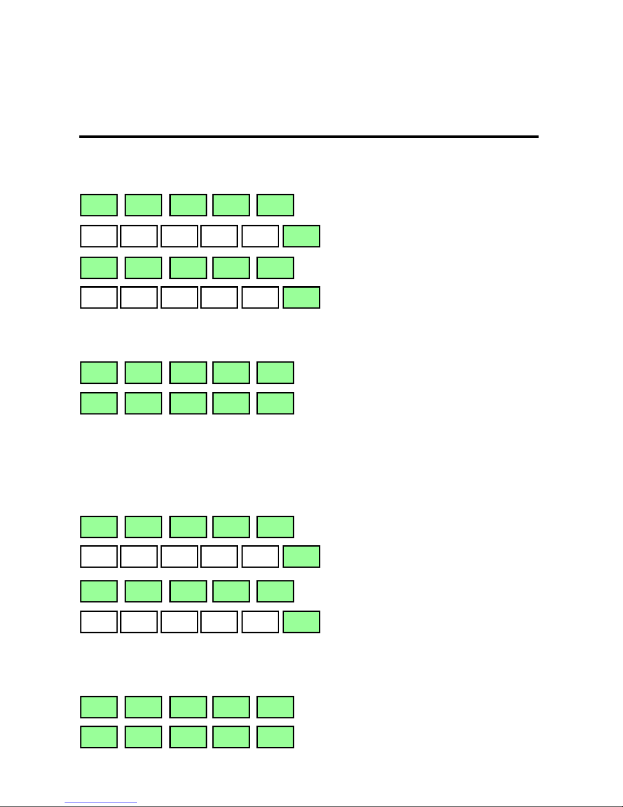
Handset Status Displays (International)
International
channels set
Private channel
operative
Private channel
operative
Channel operative
CH 10
Pre-selected channel
Scan All
operative
Channels selected for
Scan Programme
Scan Programme
operative
Dual Watch
operative
Function
in standby
Output
reduced
Set is
transmitting
Incorrect
selection
Key E, access to
secondary
functions
Squelch or volume
setting
Other handset
in use
Intercom
selected
Automatic
Distress Call
(RS8300 SOS)
INT
PCH
P3
16
10
SCAN ALL
67 16 10
SCAN PRG
- -
DW 16
SB
IW
TX
ERROR
SHIFT
3
OCC
INTERCOM
AUTO SOS
Page 9

9
US
channels set
US
weather channels
Transmission
is stopped by time-out
Handset Status Displays (US)
US
WX
TX OFF
Page 10
10
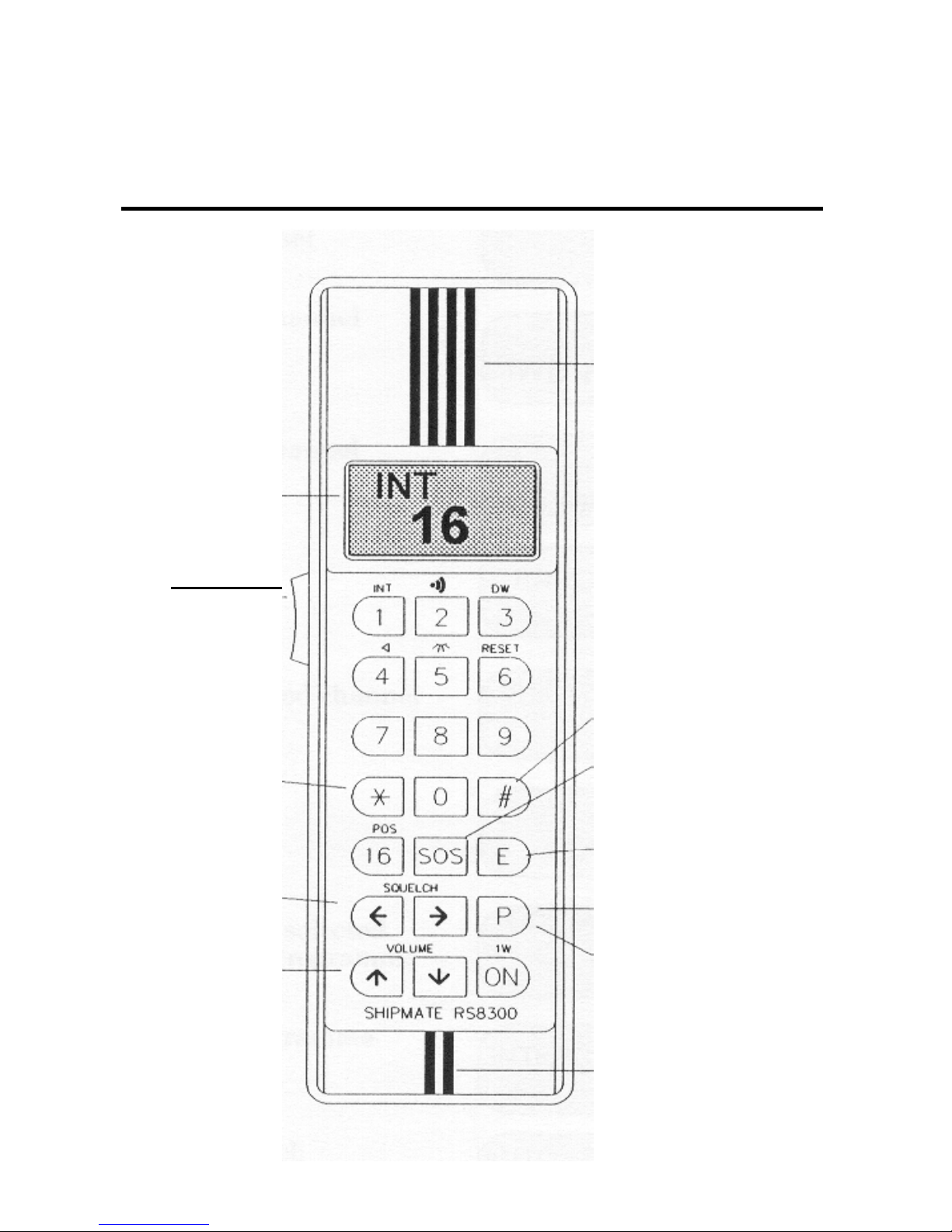
Handset Keys
Status display
(page 8,9)
PTT
Press To Transmit
Scan All
(page 18)
Squelch controls
(page 16)
Volume controls
(page 16)
Earpiece
Scan Programme
(page 20)
Automatic Distress Call
Secondary function access
(page 9)
INT (P): Private Channel
Selector (page 14)
US (WX): Private Channel Selector & Weather
channels (page 15)
Microphone
Page 11
11
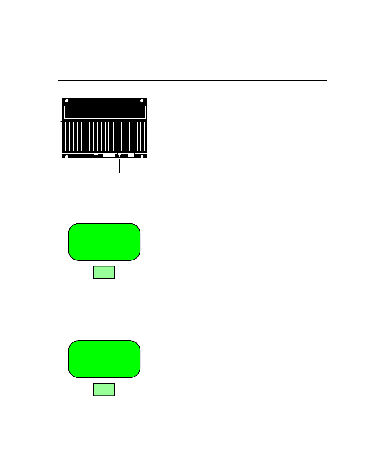
The ON/OFF switch is fitted at the base of the main unit and a stand-by facility
on the handset allows power consumption to be reduced, so that the set can be left
on almost indefinitely.
INT
16
ON
ON
ON/OFF
Set the ON/OFF switch of the main unit to the
ON position. The system will automatically return
to the same status as when it was switched OFF.
If the display remains blank, the unit is in standby mode. Press the ON key of the handset once.
The channel will be displayed and the unit will be
fully operational.
On closing down, press the ON key of the handset
and hold it down until the display turns off. The
unit is now in stand-by mode.
If the vessel is to be left unattended for any length
of time, the ON/OFF switch of the main unit
should be set to the OFF position.
Page 12

12
Position Input (RS8300 SOS only) is automatically updated if you have a GPS
navigator connected to the VHF. Without a navigator, the information can be entered manually from the keypad via the Position menu.
LA XXXXX
16
16E
LA 12N34
16
LO 103E52
16
1 2
ß
3 4
1
0
3
à
5
2
In the Position menu, the display will show the
latitude of the last transferred position from a
GPS navigator.
Note! The display is not updated while the menu
is active.
If no position is displayed, the data can be entered
manually.
F Press the E key to exit the Position menu, or...
Enter latitude e.g. 12N34
Toggle between N/S with ß / à
Go to longitude with â
Enter longitude e.g. 103E52
Toggle between E/W with ß / à
Go to UTC time with â
Page 13

13
INT
16
E
UTC 14 39
16
1 4
à
3 9
To enter UTC time in hours and minutes
e.g. 14:39 hours.
To acknowledge the position and time input,
press the E key.
DSC or Digital Selective Calling is a part of the
Global Maritime Distress and Safety System GMDSS.
This safety system ensures that all coastal stations
and commercial vessels automatically will monitor channel 70 for digital distress calls.
GMDSS is being implemented gradually and will
be fully deployed before 1999.
Page 14

14
INT
16
16
77
16
7 7
E
INT
16
P 3
E
Select the International Distress Channel and
General Calling Frequency.
Select any public channel, for example, Ship to
Ship Channel 77.
The display will change automatically after 3.5
seconds, or immediately if the E key is pressed.
Select a private authorized channel, say Private
Channel 3.
This will be displayed 3.5 seconds after selection,
or immediately after the E key is pressed.
Channel Selection allows access to all legally permissible channels. It also permits direct, single key operation for the distress and general calling frequency,
Channel 16.
Page 15

15
US
10
E 1
WX
1
1
TX OFF
10
P E
International and US channels may be used with this unit, permitting operation
in all waters.
To toggle between US system and International
channels, press the E key and 1 key. If the legend
ERROR is displayed, it indicates that US channels are not available.
US channels 13 & 67 are preset to 1W output.
This is shown by a flashing 1W on the display.
For 25W output, press and hold the PTT key and
then press the ON key. When using these channels
the handset OFF function will be inoperative.
US FUNCTION:
To select the Weather Channels.
In the International version, key WX is
exchanged with key P.
Refer to page 14 for details on the Private Channels.
US FUNCTION:
Transmitting continuously for more than 5 minutes, will cause the transmission to turn off.
To resume transmission, release the PTT key and
then press it again.
Page 16

16
INT 3
16
ß à
INT
1W16
ON
INT 3
16
á
â
E
Output Power can be set to either 1W or to 25W.
Squelch is adjustable in three steps from 1 to 3.
Volume is adjustable in eight steps from 1 to 8.
To reduce output power to 1W for short range
transmission. The unit will be set at maximum
output when switched ON.
Toggle between 1W and 25W.
When the set is switched on, the squelch setting
will be at 3. In step 1 the receiver is always open.
Adjust squelch with ß / à
When the set is switched on, the volume setting
will automatically be at 3. The speaker volume
can be increased in steps up to setting 8.
Adjust volume with á / â
Page 17

17
DW 16
10
E 3
DW SB
10
DW 16
16
Dual Watch will automatically monitor Channel 16 as well as one other channel
pre-selected by the operator. It will function only if both handsets are in their
cradles.
Activate/terminate Dual Watch.
Monitoring of Channel 16 stops when a handset is
lifted from its cradle. The pre-selected channel
immediately becomes available for communication, and the receiver changes to Stand-by ready
to resume Dual Watch when the handset is back
in its cradle.
When a signal is detected on Channel 16, the receiver stops monitoring the pre-selected channel,
and the legend 16 will be in both channel positions.
It will be locked to Channel 16 until the signals
stop or a handset is lifted for use on the preselected channel.
Page 18

18
SCAN ALL
10
SCAN ALL
- -
*
INT SB
10
Scan All mode monitors all channels for transmissions. *
Squelch must be set above level 1 before this mode can be selected. The Scan
function will go in Stand-by mode if the handset is out of its cradle.
* In Europe Channel 16 is always monitored.
Activate/terminate Scan All.
While scanning is in progress, channel numbers
will not be displayed.
When a transmission is detected, the set will lock
on for four seconds and display the number of the
channel.
When a handset is lifted, the scanning stops and
goes in stand-by mode. The display will show the
last received channel.
Page 19

19
88
10
8 8
SCAN ALL
- -
*
SCAN ALL
- -
0 *
Exclusions from Scan All can be made for up to six channels. *
This will prevent continuously transmitting stations, such as V.H.F. Direction
Beacons, from intruding.
* In Europe it is not possible to exclude Channel 16.
Set in the number of the channel to be excluded
from Scan All programme, e.g. Channel 88.
Press the * key immediately, otherwise channel
selected for exclusion will instead be “standard
channel selection”.
If excluding more than the maximum six allowed
channels, the first exclusion will be overwritten
by the last entry. Excluded channels will be memorized by the unit.
This programme will reinstate all excluded channels in a single operation.
Page 20

20
Scan Programme mode allows a limited number of channels to be monitored. *
A minimum of two and a maximum of ten channels can be pre-selected by the
operator.
* In Europe Channel 16 is always monitored together with the user-selected
channels.
SCAN PGM
10
SCAN PGM
- -
#
INT SB
10
The set will lock on to any detected signal for
four seconds, and scanning will automatically
continue unless a handset is lifted for communication. Squelch must be set to 2 or 3.
To activate/terminate Scan Programme.
While scanning takes place, channel numbers will
not be displayed.
When a transmission is detected, the set will lock
on for four seconds and display the number of the
channel.
When a handset is lifted, the scanning stops and
goes in stand-by mode. The display will show the
last received channel.
Page 21

21
Edit of Scan Programme memory. Channels selected for Scan programme will
be retained in the memory of the set, even if power is switched off. When the
memory is full (ten channels), the first one entered is overwritten by the last one
entered.
13
10
1 3
INT
10
#
13 5 18
10
9 9
#
0
#
To insert new channels in the Scan Programme
memory, e.g. Channel 13.
To delete all channels stored in Scan Programme
memory.
Display the channels stored in Scan Programme
memory.
Page 22

22
INT SB
10
INTERCOM
10
2E
The Intercom (not available in RS8300 standard) facility allows private conversation between the two handsets, or messages over separate loudspeakers, provided there is no radio traffic on the channel selected.
Pick up the handset and press the E key and the 2
key to activate Intercom.
A beep sequence will sound through the loudspeakers.
Press the PTT key to give a message over the
loudspeakers, or to communicate with the second
handset when it is out of the cradle.
Intercom will automatically go to stand-by when
a radio signal is received. Intercom is cancelled
when both handsets are returned to their cradles.
Page 23

23
INT
10
E 4
INT
10
5E
Muting completely silences the loudspeakers.
Illumination is set to the low level when the handset is switched on.
Press the E key and the 4 key to mute the loud-
speakers.
This setting is automatically cancelled when a
handset is replaced in its cradle.
Press the E key and the 5 key to adjust the level of
illumination.
This function will toggle between three levels of
illumination: low, high and off.
Page 24

INSTALLATION
ANT
12 V
#2
#1
5m
20m
+
-
DUAL SYSTEM
6.3A
POSITION & TIME
Interface setup
NMEA 0183 GLL, GGA
(Green) DATA IN
(Red) RETURN
Fuse 6.3A slow blow
Power cable: 1.5m,
2x1.5mm
2
Extendable to max.:
5m, 2x1.5mm
2
10m, 2x2.5mm
2
Speaker cable: 1.5m,
2x0.4mm
2
Extendable to max:
20m, 2x0.4mm
2
>20m, 2x0.75mm
2
(NOT RS8300 STANDARD)
Note! Do not connect 4 ohms
speakers (RS8310 speakers)
in parallel.
Page 25

25
A A
A A
SHIPMATE
Installation of transceiver unit, handset cradle and watertight socket.
(Optional).
The transceiver unit is not waterproof,
so it will have to be installed in a dry
place.
1. Fasten the transceiver unit with the
4 screws (included) in the holes
marked A.
2. Fasten the handset cradle with minimum 4 screws (included).
Take care that the cradle is not mounted upside-down, as the plastic spring
has a cutout for the cable.
3. Drill a Ø22mm hole for the watertight socket.
4. Place the socket in the hole and drill
four Ø2mm holes for the included 4
screws.
INSTALLATION
Page 26

INSTALLATION
Installation of speaker
1. Open the speaker by pressing firmly on
the top and bottom of the back part, and at
the same time pull the front part forward.
2. Drill out the appropriate holes for installation with a Ø4mm drill.
3. Lead the speaker cable through the hole
of the rear part.
4. Fasten the rear part with the included
screws.
5. Connect the speaker cables to the connection terminals.
6. Take the front part of the speaker and
press it back together with the rear part.
Note! Speakers for the dual version are
supplied with fixed cables and switch.
Page 27

27
INSTALLATION
45
25 59 6
9 69
2
2
6
9
4
8
3
0
5
3
6
.
5
-
7
85mm
How to flush mount a
speaker
1. Locate the exact position for the
speaker.
2. Cut out the hole as indicated
(shaded area).
3. Drill two Ø2mm holes.
4. Fasten with two 3x14mm selftapping screws (not included).
5. Insert the speaker into the cutout and slide it into its correct position. The two screws will lock into
two keyhole-shaped holes.
Ø2mm
Page 28

INSTALLATION
Multiple handset connections
- up to three handsets can be connected simultaneously.
Dual outlet for two or more handset
sockets.
Part no. 157.2014.001
Note! Only one handset should be
connected at a time, as the sockets
are in parallel.
Dual connection box for two handsets.
Part no. RS8321
Handset #2 and #3 will have equal
second priority, and both can intercom with #1.
#1
#2
#3
Intercom
Page 29

29
OPTIONAL PA-HAILER
(not available in RS8300 standard)
Installation and operation of
PA-HAILER
Pick up one handset.
Place the toggle switch in HAIL position.
Select Intercom
Press PTT to HAIL
Terminate the function by resetting the toggle
switch to RS8300 speaker, and place the
handset back in its cradle.
INTERCOM
10
E 2
Toggle
switch*
*Not
supplied
PA-Hailer
horn*
Page 30

TECHNICAL DATA
General
Power supply: 13.2V dc (12V nominal) isolated earth.
Reverse polarity protection.
Operating voltage: 10.8 to 15.6V dc
Power drain:
- receive: 1.8W / 150mA
- transmit (25W): 60W / 5A
- transmit (1W): 10W / 0.8A
- stand-by: 60mW / 5mA
Mode: Simplex / Semi Duplex
Channels: 54 International / US, 16 Private
Facilities: Scanning, Dual Watch, Priority Key,
DSC - class C (automatic distress call)
Frequency range: 153.9 - 163.1 MHz
Antenna impedance: 50 ohms
Connector: PL 259
Navigator input: NMEA 0183 - GLL and GGA string.
Transmitter
Power output:
- high: 23 - 25W
- low: 1W
AF distortion: <3%
Microphone sensitivity: 22mv / 600 ohms
Loudspeaker: 8 ohms, 8W
Dimensions: 110x100x47 (4.4x4x1.9”)
Weight: 0.4 kg
Page 31

31
TECHNICAL DATA
Receiver
Sensitivity: 0.3 µv / 12 dB SINAD
Squelch sensitivity: Threshold 10dB quieting max. 2 µv
AF output power: 4W / 8 ohms
Headphone output: 0.775v / 600 ohms
Construction
Main unit: Moisture resistant. Must be located inside, away from
possible exposure to water.
Dimensions: 184x155x42mm (7.2x6x1.6”)
Weight: 1 kg
Handset: Water resistant. Handset may be placed in an open
cockpit and on the flybridge.
Compass safe distance: 1m
Dimensions: 192x60x27mm (7.5x2.3x1”)
Weight: 0.25 kg
Environmental: -10° to +55°C / 95% rel.
Page 32

32
INTERNATIONAL MARINE VHF CHANNELS
C= Channel D= Duplex oo= Only DK, N, S, SF
P= Public H= Harbour nn= Only N, SF
S= Ship to Ship X= Receive only uu= Only UK
ll= 25 Watt ¤¤= 1 Watt
C D P H S Remarks C D P H S Remarks
1 • • • 60 • • •
2 • • • 61 • • •
3 • • • 62 • • •
4 • • • 63 • • •
5 • • • 64 • • •
6 • 65 • • •
7 • • • 66 • • •
8 • 67 •
9 • • 68 •
10 • • 69 • •
11 • 70 DIGITAL SELCALL
12 • 71 •
13 • • 72 •
14 • 73 • •
15 • • 74 •
16 SAFETY & CALLING CHANNEL 77 •
17 • • 78 • •
18 • • 79 • •
19 • • 80 • •
20 • • 81 • •
21 • • 82 • • •
22 • • 83 • •
23 • • 84 • • •
24 • • 85 • •
25 • • 86 • •
26 • • 87 • •
27 • • 88 • •
28 • •
P1 uu 157.850 MHz P1 = L1 ¨¨ 155.500 MHz
P2 uu 161.425 MHz P2 = L2 ¨¨ 155.525 MHz
P3 P3 = L3 n 155.650 MHz
P4 P4
Page 33

33
C= Channel D= Duplex •= 25 Watt
P= Public H= Harbour ¤¤= 1 Watt
S= Ship to Ship ««= Receive only uu= USCG only
C D P H S Remarks C D P H S Remarks
1 • • 60 • • •
2 • • 61 • • •
3 • • 62 • • •
4 • • 63 • •
5 • • 64 • • •
6 • Safety 65 • •
7 • • 66 • •
8 • 67 ¤¤
9 • • 68 • •
10 • • 69 • •
11 • • 70 DIGITAL SELCALL
12 • • 71 • •
13 ¤¤ ¤¤ 72 •
14 • • 73 • •
15 «« 74 • •
16 SAFETY & CALLING CHANNEL 77 •
17 ¤¤ State controlled 78 •
18 • • 79 •
19 • • 80 •
20 • • 81 uu uu
21 uu uu 82 uu uu
22 uu uu 83 uu
23 uu 84 • • •
24 • • Marine operator 85 • •
25 • • Marine operator 86 • •
26 • • Marine operator 87 • •
27 • • Marine operator 88 •
28 • • Marine operator
WX1 WEATHER 162.550 MHz «« WX6 WEATHER 162.500 MHz ««
WX2 WEATHER 162.400 MHz «« WX7 WEATHER 162.525 MHz ««
WX3 WEATHER 162.475 MHz «« WX8 WEATHER 161.650 MHz ««
WX4 WEATHER 162.425 MHz «« WX9 WEATHER 161.775 MHz ««
WX5 WEATHER 162.450 MHz «« WX10 WEATHER 163.275 MHz ««
US & CANADIAN MARINE VHF CHANNELS
Page 34

Warranty
SIMRAD warrants that every product shall be free of defects in material and
workmanship as specified below:
CATEGORY “A”: *Autopilots *Radars *Instruments *Navigators *Radiotelephones *Plotters *Gyro compasses *Sonars *Echo sounders *Trawl Instrumentation.
These products are warranted for a period of 24 months on parts and 12 months
on labour from date of purchase, except for category B items. Consumable parts
such as lamps, fuses, batteries, bearings etc. are not covered by this warranty.
CATEGORY “B”: *Antennas *Transducers *Trawl sensors *Monitors (CRT)
*Gyro sensitive elements *Radar magnetrons *Disk drives.
These items are warranted for a period of 12 months on parts and labour from date
of purchase.
WARRANTY SERVICE is available through authorised service dealers or national distributors worldwide. Products returned will, at the sole discretion of Simrad, either be repaired or replaced free of charge within normal working hours.
Freight charges, insurance, duties or any other costs are the responsibility of the
customer.
Maximum liability shall not, in any case, exceed the contract price of the products
claimed to be defective.
ON BOARD SERVICE can be arranged by authorised local service dealers or
national distributors upon request. Labour costs for the repair/replacement of the
defective modules/parts will be free of charge provided a valid warranty is confirmed. Overtime, travel, lodging, per diem, insurance, duties or any other costs
are the responsibility of the customer. Additional expenses connected with replacement of transducers such as dry docking, diving and precautionary measures
are not covered by this warranty.
VALIDITY: This warranty is effective only when warranty certificate or proof of
purchase and equipment serial number is presented. Furthermore, the installation
and operation has to be carried out in accordance with the product manual. Warranty liability does not apply to any equipment which has become inoperative due
to misuse, accident, neglect, sea water damage or unauthorised repair. Simrad will
not be liable for any loss, incidental or consequential damages whether based
This text is intentionally left blank!upon warranty, contract or negligence, or arising in connection with the sale, installation, use or repair of the product. Consequential damages include, but are not limited to, any loss of profit, property damage or personal injury.
The terms of warranty as described does not affect your statutory rights.
 Loading...