

Page 1

Installation manual
TECHNOLOGY FOR SUSTAINABLE FISHERIES
www.simrad.com
Simrad SH90
Fish nding sonar
Page 2

Page 3

SimradSH90
Installationmanual
Thismanualprovidesyouwiththebasicinformation
requiredtoinstalltheSimradSH90.Formoredetailed
informationaboutthepracticaluseoftheproduct,referto
theSimradSH90OperatormanualortheSimradSH90
Referencemanual.
323776/A
09.06.2010
Page 4

History
KongsbergM a r it imeA S
Strandprom e n a de n5 0
P.O.Bo x1 11
N- 3 1 91H o rten ,N o rway
S im ra d
Teleph on e :+ 473 30 34 00 0
Telefa x:+ 473 30 42 98 7
contact@ s im ra d . com
w w w .s im r a d . c o m
Documentno:323776/V ersion:A/ISBN-13:978-82-8066-125-1
Rev.A09.06.2010
Firstissue.
Copyright
©2010KongsbergMaritimeAS
TheinformationcontainedinthisdocumentremainsthesolepropertyofKongsbergMaritimeAS.Nopart
ofthisdocumentmaybecopiedorreproducedinanyformorbyanymeans,andtheinformationcontained
withinitisnottobecommunicatedtoathirdparty ,withoutthepriorwrittenconsentofKongsberg
MaritimeAS.Thedocument,oranypartofit,maynotbetranslatedtoanyotherlanguagewithoutthe
writtenapprovalfromKongsbergMaritimeAS.
Disclaimer
KongsbergMaritimeASendeavourstoensurethatallinformationinthisdocumentiscorrectandfairly
stated,butdoesnotacceptliabilityforanyerrorsoromissions.
Warning
Theequipmenttowhichthismanualappliesmustonlybeusedforthepurposeforwhichit
wasdesigned.Improperuseormaintenancemaycausedamagetotheequipmentand/orinjury
topersonnel.Theusermustbefamiliarwiththecontentsoftheappropriatemanualsbefore
attemptingtoinstall,operateorworkontheequipment.
KongsbergMaritimeASdisclaimsanyresponsibilityfordamageorinjurycausedbyimproper
installation,useormaintenanceoftheequipment.
Supportinformation
Ifyourequiremaintenanceorrepair,contactyourlocaldealer.Youcanalsocontactususingthefollowing
address:contact@simrad.com.Ifyouneedinformationaboutourotherproducts,visitourwebsite.On
thewebsiteyouwillalsondalistofourdealersanddistributors.
Page 5

Installationmanual
Tableofcontents
ABOUTTHISMANUAL.....................................................11
SIMRADSH90.................................................................13
Basicinformation...................................................................................................13
Mainunits...............................................................................................................14
Wheelhouseunits........................................................................................14
Sonarroomunits.........................................................................................15
Systemdiagram......................................................................................................17
Installationprocedure.............................................................................................18
Scopeofsupply......................................................................................................20
Additionalrequireditems.......................................................................................20
DisplayUnit.............................................................................................20
UninterruptedPowerSupply(UPS)..............................................................20
Installationtrunk.......................................................................................21
Speedlog...................................................................................................21
Coursegyro................................................................................................21
Additionaloptionalitems.......................................................................................22
Installationtrunk.........................................................................................22
Scienticinterface......................................................................................22
Otherperipheralequipment.........................................................................23
Generalsupplyconditions......................................................................................24
Equipmentresponsibility.............................................................................24
Receipt,unpackingandstorage....................................................................25
Generalinstallationrequirements...........................................................................25
Approvalbyclassicationsociety................................................................25
Supplypower.............................................................................................26
Compassdeviation......................................................................................26
Noisesources.............................................................................................26
Drydocking...............................................................................................26
Wiring........................................................................................................26
Supportinformation...............................................................................................27
INSTALLATIONPLANNING..............................................28
Aboutinstallationdrawings....................................................................................28
Locationofthehullunit.........................................................................................29
Sonarroomrequirements.......................................................................................31
Sonarroomarrangementexample..........................................................................33
Sonarroomarrangementexample................................................................33
Sonarroomarrangementexample................................................................34
Hullunitorientationexample.......................................................................35
323776/A
3
Page 6

SimradSH90
SONARTRUNKINSTALLATION........................................36
Mountingthesonartrunk.......................................................................................37
Sonartrunkprotection............................................................................................38
Sonartrunkinstallationprinciples..........................................................................38
Sonartrunkinstallationmeasurements...................................................................41
HULLUNITINSTALLATION.............................................42
Howtounpackthehullunitfromitstransportbox...............................................43
Hullunitmounting.................................................................................................45
Mechanicalsupport................................................................................................47
Transduceralignment.............................................................................................47
Hullunitinstallationchecklist...............................................................................48
TRANSCEIVERUNITANDPOWERSUPPLYUNIT
INSTALLATION...............................................................49
TransceiverUnitpreparations................................................................................49
PowerSupplyUnitpreparations.............................................................................50
TransceiverUnitinstallationprocedure.................................................................50
PowerSupplyUnitinstallationprocedure..............................................................54
WHEELHOUSEUNITSINSTALLATION..............................55
Physicallocationofwheelhouseunits....................................................................55
Installationrequirements.............................................................................56
Locationofthecolourdisplay......................................................................56
LocationoftheOperatingPanel...................................................................57
LocationoftheOperatingPanelPowerSupply.............................................57
LocationoftheProcessorUnit.....................................................................57
Maximumdistancesbetweentheunits...................................................................58
Installationofthecolourdisplay............................................................................59
InstallationoftheOperatingPanel.........................................................................59
InstallationoftheOperatingPanelPowerSupply.................................................60
InstallationoftheProcessorUnit...........................................................................60
UPSINSTALLATION........................................................62
CABLELAYOUTANDINTERCONNECTIONS......................63
Cableplan...............................................................................................................64
Listofcables..........................................................................................................66
Cableprocedures....................................................................................................72
ConnectACmainstotheUninterruptedPowerSupply..................................72
ConnectthevideocablefromtheProcessorUnittothecolourdisplay...........73
ConnecttheUSBcablefromtheOperatingPaneltotheProcessorUnit...........74
ConnecttheOperatingPanel“Dualcable”....................................................75
ConnecttheOperatingPanelpowersupplytotheProcessorUnit...................76
ConnectACmainsandgroundtotheProcessorUnit.....................................77
4
323776/A
Page 7

Installationmanual
ConnectACmainstothecolourdisplay.......................................................78
ConnectgroundtotheOperatingPanel........................................................79
ConnecttheProcessorUnittotheTransceiverUnit.......................................80
ConnectACmainstotheTransceiverUnit...................................................81
ConnectthepowercablefromthePowerSupplyUnittotheTransceiver
Unit...........................................................................................................82
ConnecttheEthernetcablefromthePowerSupplyUnittotheTransceiver
Unit...........................................................................................................83
ConnectACmainsandgroundtothePowerSupplyUnit..............................84
ConnectACmainstotheMotorControlUnit...............................................85
ConnecttheTransceiverUnittotheMotorControlUnit................................86
ConnecttheEthernetcableforscienticoutput.............................................87
Transducercable.........................................................................................88
Installationofinterfacecablestoperipheralequipment..................................88
ProcessorUnitseriallines......................................................................................88
Seriallinesupport.......................................................................................88
JumperandDIPswitchsettings...................................................................89
Adaptercable.............................................................................................91
Referencestodetailedcabledrawingsandspecications......................................92
START-UPPROCEDURES.................................................93
StartinguptheHullUnit........................................................................................93
Hullunitfamiliarization..............................................................................94
MotorControlUnitfamiliarization...............................................................95
Functionalcheck.........................................................................................96
Apply3-phaseACpower............................................................................97
Checkthehoistingmotor’s3–phaseACconnections.....................................98
Checkthe3–phaseconnectionforcorrectrotationdirection...........................99
Checkthecontactoroperation....................................................................100
Functionalchecktoverifycorrecthoistandlowerfunctionality...................101
Startingthewheelhouseunits...............................................................................103
CheckingtheOperatingPanel..............................................................................104
Functionaltest..........................................................................................104
Startingupthesonarroomunits..........................................................................112
Checkingthehoist/lowersystem..........................................................................113
Checkingthebridgefunctions....................................................................114
Checkingthesonarroomfunctions.............................................................116
Performself-noisetest..........................................................................................117
Startingupthesonarsystem.................................................................................118
Preparations..............................................................................................118
Actionsonthebridge.................................................................................119
Actionsinthesonarroom..........................................................................120
Alignmentofthesonarpicture.............................................................................121
323776/A
5
Page 8

SimradSH90
Deningownshipparameters..............................................................................122
Specifyshipdimensions............................................................................122
Specifyinstrumentpositionoffsets.............................................................122
INTERFACINGPERIPHERALEQUIPMENT......................124
Interfaceandtelegramsoverview.........................................................................124
Interfacesettings...................................................................................................127
Defaultinterfacesettings...........................................................................127
Howtochangetheinterfacesettings..........................................................127
Howtomonitorthetrafconaserialline...................................................132
Synchronisationwithotheracousticsystems.......................................................133
Aboutsynchronisation..............................................................................133
SH90setupasSlave.................................................................................134
SH90setupasMaster...............................................................................134
Synchronisationsequences........................................................................135
Installationprocedures.........................................................................................136
Connectingthespeedlog...........................................................................136
Connectingthecoursegyro.......................................................................137
Testprocedures.....................................................................................................138
Speedloginterfacetest.............................................................................138
Coursegyrointerfacesetupandtest...........................................................139
Positioningsysteminterfacesetupandtest.................................................140
Echosoundersysteminterfacesetupandtest..............................................141
Trawlsysteminterfacesetupandtest.........................................................141
Catchmonitoringinterfacesetupandtest...................................................142
Radiobuoysysteminterfacesetupandtest.................................................143
Currentmeterinterfacesetupandtest.........................................................143
FINALTESTSANDMEASUREMENTS..............................145
Noise/speedcurvemeasurements.........................................................................146
Preparations.............................................................................................146
Testprocedure..........................................................................................146
Problemswithownoise..........................................................................147
Noise/speedtestresults.............................................................................147
ProcessorUnitbackupandrestore.......................................................................150
HowtocreateabackupDVD....................................................................150
HowtorestorefromabackupDVD...........................................................150
HowtoreactivatetheWindowslicence......................................................151
TECHNICALSPECIFICATIONS.....................................157
Powerspecications...........................................................................................157
Weightsandoutlinedimensions.........................................................................158
Environmentalspecications.............................................................................160
Performancespecications.................................................................................161
6
323776/A
Page 9

Installationmanual
DRAWINGFILE.............................................................163
TransceiverUnitdimensions................................................................................164
Forwardview...........................................................................................164
Sideview.................................................................................................165
Topview..................................................................................................166
PowerSupplyUnitdimensions............................................................................167
Forwardview...........................................................................................167
Sideview.................................................................................................168
ProcessorUnitdimensions...................................................................................169
OperatingPaneldimensions.................................................................................170
SH90Hullunitdimensions..................................................................................171
SH90Sonartrunkdimensions..............................................................................172
SH90Sonartrunkproduction...............................................................................173
Sideview.................................................................................................173
Topview..................................................................................................174
SH90Blindcoverdimensions..............................................................................175
AGENERALSAFETYRULES...............................................176
BEQUIPMENTHANDLING................................................177
Transportation.......................................................................................................177
Lifting...................................................................................................................177
Storagepriortoinstallationoruse.......................................................................178
Inspection.............................................................................................................179
Unpacking............................................................................................................180
Generalunpackingprocedure....................................................................180
Unpackingelectronicandelectromechanicalunits......................................181
Unpackingmechanicalunits......................................................................181
Unpackingtransducers..............................................................................181
Storageafterunpacking........................................................................................182
Storageafteruse...................................................................................................182
Cleaningcabinets......................................................................................182
Mechanicalunits.......................................................................................183
Cables......................................................................................................183
Internalbatteries.......................................................................................183
Dehumidier............................................................................................184
Coatings...................................................................................................184
Re-packaging........................................................................................................184
Temperatureprotection.........................................................................................184
Circuitboardhandlingandpackaging..................................................................185
Returningacircuitboard...........................................................................186
Electro-StaticDischarge(ESD)............................................................................186
CSH90CABLEDETAILS...................................................188
323776/A
7
Page 10

SimradSH90
Cablingprinciples.................................................................................................188
Cablestoperipheraldevices.................................................................................189
Positioningsysteminterface......................................................................189
Echosoundersysteminterface...................................................................190
Trawlsonarinterface.................................................................................190
Catchmonitoringsysteminterface.............................................................191
Currentmeterinterface..............................................................................191
Radiobuoysconnectioninterface...............................................................191
Cabledrawings.....................................................................................................193
MoxaCP-134U-Iserialadapter.................................................................194
Vesselground...........................................................................................196
ACmains(IEC60320)..............................................................................197
ACmainstoMotorControlUnit................................................................198
ACmainswithIEC320/C7.......................................................................199
DCpowersupply.....................................................................................200
DCpowerfromPowerSupplyUnittoTransceiverUnit.............................201
RJ45Ethernet,straight..............................................................................202
RJ45Ethernetwithnoisesuppressor..........................................................203
VGA/SVGADisplay.................................................................................204
UniversalSerialBus(USB).......................................................................205
DVI–IDisplay..........................................................................................206
OperatingPanel“Dual”............................................................................208
DBASICCABLEREQUIREMENTS......................................209
Cabletrays............................................................................................................209
RadioFrequencyinterference..............................................................................210
Physicalprotection...............................................................................................210
Grounding.............................................................................................................211
Cableconnections.................................................................................................211
Cableterminations................................................................................................211
Cableidentication...............................................................................................212
ETELEGRAMFORMATS....................................................213
AboutNMEAtelegramformats...........................................................................213
TelegramsreceivedandsentbytheSH90............................................................214
Coursegyrotelegrams...............................................................................214
Speedlogtelegrams..................................................................................215
GPStelegrams..........................................................................................215
ITIandtrawlsystemtelegrams..................................................................215
Echosoundertelegrams.............................................................................216
Windsensortelegrams..............................................................................217
Seacurrenttelegrams................................................................................217
Catchmonitoringsystemtelegrams............................................................217
Buoytelegrams.........................................................................................217
8
323776/A
Page 11

Installationmanual
Targetoutputtelegrams.............................................................................218
SpecicationofNMEAtelegrams.......................................................................218
DBSDepthbelowsurface.........................................................................218
DBTDepthbelowtransducer.....................................................................218
DPTDepth...............................................................................................219
GGAGlobalpositioningsystemxdata.....................................................219
GLLGeographicalpositionlatitude/longitude............................................220
HDGHeading,deviationandvariation.......................................................220
HDMHeading,magnetic...........................................................................221
HDTHeading,true...................................................................................221
MWDWinddirectionandspeed................................................................222
MWVWindspeedandangle.....................................................................222
RMCRecommendedminimumspecicGNSSdata....................................222
VBWDualgroundandwaterspeed...........................................................223
VHWWaterspeedandheading.................................................................224
VTGCourseoverground&groundspeed..................................................224
VWRRelative(apparent)windspeedandangle..........................................224
ZDATimeanddate..................................................................................225
SpecicationofproprietarySimradtelegrams.....................................................225
DBSDepthoftrawlbelowsurface.............................................................225
FS3300Binarydepth................................................................................226
GLLTrawlposition..................................................................................226
HFBTrawlheadropetofootropeandbottom..............................................226
MDSMeasureddatashoal.........................................................................227
MTWWatertemperatureatthetrawl.........................................................228
PSIMP-FPISensordenition....................................................................228
PSIMP-DPISensordata...........................................................................229
TDSTrawldoorspread.............................................................................230
TFITrawllling.......................................................................................230
TPCTrawlpositionincartesiancoordinates...............................................231
TPPTrackedtargetpositionormarker.......................................................231
TPTTrawlpositiontruevessel..................................................................232
TS2Trawlspread2...................................................................................232
TTSTrawltoshoaldistance......................................................................232
Specicationofproprietarythirdpartytelegrams................................................233
VDVCDV ectorcurrentdirection...............................................................233
FurunoCIF...............................................................................................233
SerpeBSCBuoyinput..............................................................................236
RyokoseiRBYBuoyinput........................................................................237
FINSTALLATIONREMARKS.............................................238
323776/A
9
Page 12

SimradSH90
10
323776/A
Page 13

ABOUTTHISMANUAL
Aboutthismanual
Purpose
Thepurposeofthismanualistoprovidetheinformationand
basicdrawingsrequiredforinstallationoftheSimradSH90.
Formoredetailedinformationaboutthepracticaluseofthe
product,refertotheSimradSH90Operatormanualorthe
SimradSH90Referencemanual.
Aboutthetechnicaldescriptionsandthetarget
audience
ThismanualdescribestheinstallationoftheSimradSH90.
Themanualisintendedfortechnicalpersonnel;qualied
maintenanceengineersandtechnicians.Itisassumedthatthe
personnelisconversantwiththegeneralprinciplesofmaritime
electronicequipment,inparticularsonar,echosounderandcatch
monitoringsystems.Thepersonnelmustalsobefamiliarwith
computerhardware,signalprocessing,interfacetechnology
andtraditionaltroubleshootingonelectronicandmechanical
products.
Theinstructionsmustbefollowedcarefullytoensureoptimal
performance.Asaguide,installationproceduresarepresented
intheordertheyaretobeperformed.Successfulcompletion
ofeachprocedureistobeconrmedbycheckingoffthe
correspondingbox.
Note
Theinstallationinstructionsgiveninthisdocumentmustbe
adheredto.Failuretodosomayrendertheguaranteevoid.
KongsbergMaritimeASwillacceptnoresponsibilityforany
damageorinjurytothesystem,vesselorpersonnelcausedby
equipmentthathasbeenincorrectlyinstalledormaintained,
orbydrawings,instructionsorproceduresthathavenotbeen
preparedbyus.
Theequipmentdescribedinthismanualincludesthecomplete
systemwithassociatedcabinets,butnotsystemunitsprovided
locallybythecustomer,installationshipyardorlocaldealer.The
manualalsodenestheequipmentresponsibility,andprovides
instructionsforunpackingandstorage.
Afterinstallation,thisdocumentmustbestoredonboard
thevesselforlaterreferencewhenupdatingorservicingthe
equipment.
323776/A
11
Page 14

SimradSH90
Installationdrawings
Detailedvesselspecicmechanicaldrawingsfortheinstallation
mustbeprovidedbythecustomer,oranyshipyardcontractedto
performtheinstallation.
KongsbergMaritimeASmay,onspecialorder,provideassistance
tothesedrawings.Drawingsmustbeapprovedbytheappropriate
vesselcerticationauthoritypriortoinstallationofthesystem.
Applicableoutlinedimensionandproductionsdrawings
areprovidedintheDrawinglechapter.Drawingsmay
alsobedownloadedinPDFand/orDWGformatsfrom
t t p : / / w w w . s i m r a d . c o m .
h
References
ThefollowingusermanualshavebeenprovidedfortheSimrad
SH90.EnglishmanualsareprovidedwiththeSH90whenitis
shipped.Whenavailable,manualsinotherlanguagesmaybe
downloadedfromh
t t p : / / w w w . s i m r a d . c o m .
•SimradSH90InstallationManual,English[323776]
•SimradSH90OperatorManual,English[323773]
•SimradSH90ReferenceManual,English[323775]
12
323776/A
Page 15

SIMRADSH90
SimradSH90
StudythischaptertofamiliarizeyourselfwiththeSimradSH90.
Topics
•Basicinformationonpage13
•Mainunitsonpage14
•Systemdiagramonpage17
•Installationprocedureonpage18
•Scopeofsupplyonpage20
•Additionalrequireditemsonpage20
•Additionaloptionalitemsonpage22
•Generalsupplyconditionsonpage24
•Generalinstallationrequirementsonpage25
•Supportinformationonpage27
Relatedtopics
•Generalsafetyrulesonpage176
•Equipmenthandlingonpage177
•Basiccablerequirementsonpage209
Basicinformation
TheSimradSH90isanomnidirectionalhighfrequencysonar.
Itisdesignedforallsizedshingvessels,bothpurseseiners
andtrawlers.
Theoperationalfrequencyis114kHz.Thecylindrical
multi-elementtransducerallowstheomnidirectionalsonarbeam
tobetiltedelectronicallyfrom+10to–60degrees.Thisallows
youtoautomaticallytrackschoolsofsh,andtoobservethe
wholewatervolumearoundthevessel.Astabilisingsystemis
includedforelectronicpitchandrollcompensation.
Greatemphasishasbeenplacedongivingthebestpossible
presentationsonahighresolutioncolourdisplay.
TheSH90ProcessorUnitiscontrolledbyMicrosoft’sWindows
®
XP
operatingsystem,whichresultinaexiblechoiceofdisplay
modesforalargerangeofuserapplications.
Thesignalprocessingandbeamformingisperformedinafast
digitalsignalprocessingsystemusingthefulldynamicrange
ofthesignals.
Inadditiontothetraditionalsinglefrequencytransceiversystem,
theSimradSH90containsanadvancedfrequencymodulated
ltersystem(FM).
323776/A
13
Page 16

SimradSH90
Mainunits
TheSimradSH90comprisesthefollowingunits:
Normallyinstalledinthewheelhouse:
•DisplayUnit
•OperatingPanel
•ProcessorUnit
•OperatingPanelpowersupply
Normallyinstalledinthesonarroom:
•TransceiverUnit
•PowerSupplyUnit
•HullUnit
Wheelhouseunits
DisplayUnit
Thecolourdisplayisahigh-resolutionmonitor.Inaddition
tothesonarpicture,themonitorwillalsodisplaythemenu
systemfortheinteractiveoperation.Inordertoeasethesituation
comprehension,certaincolourshavebeenchosentobetterthe
distinctionbetweenthevariouselementsinthepresentation.
Thecolourdisplayisnotapartofthesonardelivery ,anditmust
bepurchasedlocally.
OperatingPanel
Figure1OperatingPanel
TheOperatingPanelcontainsallnecessarycontrolfunctionsfor
normaloperationofthesonar.
Thecontrolsarearrangedinlogicalfunctiongroups,thisgivesa
clearandeasyoperation.
Notethatallsonaroperationcanalsobemadeusingthetrackball
ontheOperatingPanelandthemenusystem.Y oucanalsousea
standardcomputermouse.
ProcessorUnit
TheProcessorUnitisamarinecomputerbasedontheMicrosoft
WindowsXP®operatingsystem.Itisdesignedforruggeduse.
14
323776/A
Page 17

SimradSH90
Thecomputerisbasedonacommercialdesign,butthesoftware
andhardwarehasbeenspeciedandassembledbySimradtosuit
theSH90requirements.
ThecomputerholdsaDVDplayerforusewithfuturesoftware
upgrades.
Figure2ProcessorUnit
Thepurposeofthiscomputeristoallowyoutocontrolthesonar.
Thecomputerservesseveralfunctions.
•Itcontrolstheoveralloperationofthesonarfunctions.
•Itprovidesthegraphicpresentationofthesonarmodesand
echoes.
•Itholdsthemenusystem.
•ItcommunicateswiththeOperatingPaneltoreadthebuttons
andtrackballmovements.
•Itperformstheadvancedsignalprocessingandbeamforming
requiredtopresenttheinformationonthedisplay.
•Itcommunicateswithperipheraldevicesandsensorsusing
seriallines.
•ItcommunicateswiththeTransceiverUnit.
OperatingPanelpowersupply
Asmallpowersupplyisimplementedtoprovidestand-bypower
totheOperatingPanel.Thepowersupplyisconnectedtothe
ProcessorUnit.
Sonarroomunits
TransceiverUnit
TheSH90TransceiverUnitislocatedinthesonarroom,closeto
theHullUnit.
Thetransceiverperformsthetransmissionandreceptioncontrol
ofthe480transmittersand480receiverchannels.16identical
transceiverboardsareused.Adedicatedpowersupplyis
providedtosupplytherequiredDCvoltagestothetransceiver.
OneEthernetcableisusedforcommunicationwiththeProcessor
323776/A
15
Page 18

SimradSH90
Unitinthewheelhouse,andasecondEthernetcableisusedto
controlthehullunit.ThethirdEthernetcableconnectstothe
PowerSupplyUnit.
Thetransducercablesfromthehullunitarepluggedintotheside
walloftheTransceiverUnitcabinetusingaspecialplug.
TheTransceiverUnitismountedonthebulkheadusingpowerful
shockabsorbers.Theconnectorsforpowerandinterfaceare
locatedatthebottomofthecabinet.
PowerSupplyUnit
Adedicatedpowersupplycabinetisusedtoprovidethe
TransceiverUnitwithoperationalpower.
WARNING
Thepowersupplycabinetcontainshighvoltages.
DonotopenthecabinetdoorwhiletheSH90is
switchedon.
HullUnit
TheHullUnitisdesignedtolowerthetransducer1.0meters
belowtheship’shull.
Thetransducercanalsobeloweredtoanyselectedmiddle
position.Incaseofvoltagefailure,thetransducercanberaised
orloweredmanuallybymeansofahandcrank.
Thesensorfortheelectronicstabilisationofthesonarbeams
ishousedintheMotorControlUnit,whichismountedonthe
HullUnit.
WARNING
Ifthetransducerhitslargerobjectsorbottom,the
transducershaftmaybebent,or-inworstcaseitcanbebrokenoff.Abrokentransducershaftwill
causewaterleakagethroughthetopoftheshaft.
Insuchcases,d
itsupperposition.
Topreventseriousdamage,youmusthaveawater
pumpandawarningsysteminthesonarroom.
o n o t raisethetransducershaftto
Transducer
ThecylindricalTransducerallowsthesonarbeamtogivefull
360degreescoverageofthewatervolumefrom+10anddown
to-60degrees.
16
323776/A
Page 19
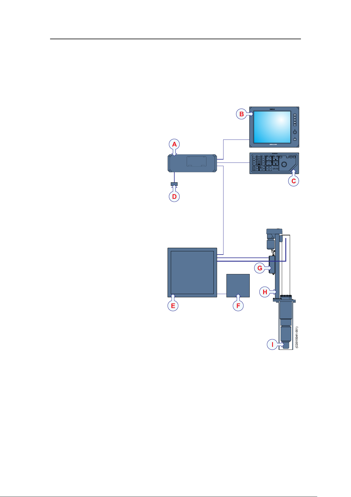
Systemdiagram
SIMRAD
PWR
MENU
SIMRAD
SIMRADSX90
(CD015041-001)
D
B
C
E F
H
G
I
A
Figure3SH90Simpliedsystemdiagram
AProcessorUnit
BDisplayUnit
COperatingPanel
DOperatingPanelpowersupply
ETransceiverUnit
FPowerSupplyUnit
GMotorControlUnit
HHullUnit
ITransducer
SimradSH90
323776/A
17
Page 20

SimradSH90
Installationprocedure
TheSimradSH90isacomplexandadvancedproductfor
professionaluse.
Note
Inordertoobtainmaximumsafetyandperformance,itisvery
importantthattheinstallationproceduresinthismanualare
compliedto,andthatthetasksarecarriedoutinthesuccession
theyaredescribed.Thevesselownermustmakesurethatthe
installationshipyardholdstheapplicablecompetencetoperform
theinstallation,andthattheapplicablemaritimeauthoritiesare
availabletoverifyandcertifytheinstallation.
ObservethebasicrequirementsinGeneralsafetyruleson
page176!
Anoverallinstallationprocedureisprovidedbelow.The
proceduredoesnotdescribeanydetailedtasks,butreferstothe
relevantproceduresinthismanual.
1Basedonthevesseldrawingsandbestpractice,
determinewherethehullunitshallbelocated.Necessary
considerationsmustbetakentoavoidacousticandelectric
disturbances.Makesurethatthesonarroommeetsthe
specicationsprovided.RefertoInstallationplanningon
page28.
2Performthephysicalinstallationofthesonartrunk.The
installationshipyardmustprovideallnecessaryinstallation
drawingsinordertocarryoutthisoperation,andifrequired,
thesedrawingsmustbeapprovedbytheapplicablemaritime
authorities.Thetrunkpenetratesthehull,anditistherefore
acrucialpartofthehullunitassembly.RefertoSonartrunk
installationonpage36.
3Installthehullunit.Duetoitsphysicalsizeandweight,and
thefactthatthetrunkpenetratesthevesselhull,itisvery
importantthatthehullunitisinstalledandsecuredproperly.
RefertoHullunitinstallationonpage42.
4InstalltheTransceiverUnit.RefertoTransceiverunitand
PowerSupplyUnitinstallationonpage49.
5Installthewheelhouseunits.RefertoWheelhouseunits
installationonpage55.
6Performthesystemcabling.Observetheprocedureand
cableplaninsectionCablelayoutandinterconnectionson
page63.Foradditionalinformation,refertoSH90cable
18
323776/A
Page 21

SimradSH90
detailsonpage188.Generalrequirementsforthecabling
areprovidedinBasiccablerequirementsonpage209.
7Performthestart-upproceduresasdetailedinsection
Start-upproceduresonpage93.
Note
Inordertosetupthesonarsysteminasafeandcorrect
manner,thesestart-upproceduresmustbecompliedto!
8Connecttheperipheralunits.Observethesetupandtest
proceduresinsectionInterfacingperipheralequipmenton
page124.Foradditionalinformation,refertoSH90cable
detailsonpage188.Generalrequirementsforthecabling
areprovidedinBasiccablerequirementsonpage209.
9Checkthesourcelevelandreceivingvoltageresponse,
andmakethenoise/speedmeasurements.Observethe
proceduresinsectionFinaltestsandmeasurementson
page145.
10Createabackupofallthesoftwareandinstallationsetup
parametersontheProcessorUnit.SeeProcessorUnit
backupandrestoreonpage150.
11FillinandsigntheInstallationRemarksform,andsenditto
Simrad’ssupportdepartmentasspeciedontheform.See
Installationremarksonpage238.
323776/A
19
Page 22

SimradSH90
Scopeofsupply
Mainunitsincludedwiththestandarddelivery
•OperatingPanel[SH8-203593]
•ProcessorUnit[327202]
•PowerSupplyUnit[327208]
•TransceiverUnit[327203]
•HullUnit[327204]
Additionalrequireditems
Thefollowingadditionalitemsarerequiredforafullyoperational
sonar,buttheyaren
•Colourdisplay
o t i n c l u d e d inthestandarddelivery:
•UninterruptedPowerSupply(UPS)
•Installationtrunk
•Speedlog
•Coursegyro
DisplayUnit
TheSimradSH90requiresaVGAorDVIcolourdisplaywitha
resolutionofatleast1280x1024pixels.
UninterruptedPowerSupply(UPS)
InordertoensurecontinuousoperationoftheSimradSH90
independentofvaryingqualityofthevessel’smainssupply,the
useofuninterruptedpowersupplies(UPS)isrequired.TwoUPS
unitsareused:
•Oneisusedtopowerthewheelhouseunits.
•OneisusedtopowertheTransceiverUnit.
Theuninterruptedpowersupply(UPS)unitsaren
thestandarddelivery.Severalcommercialtypesareavailable.
TochoosethebestUPSforthesonarinstallation,consider
environmentalconditions,spaceavailable,theavailabilityand
durationofthebatteries,andthepowerrequirementsofthesonar
units.
o t includedin
20
323776/A
Page 23

SimradSH90
MinimumUPSpowerspecications
•Inputvoltage:Musttvesselsupplyvoltage
•Outputvoltage:230V ac,50Hz
•Outputpower:
–Wheelhouseunits:600W
–Sonarroomunits:1500W
•Outputrequirement:TheACoutputvoltagemustbeasine
wave
Installationtrunk
Theinstallationtrunkrequiredforthehullunitinstallationisn
includedinthestandarddelivery.
Theinstallationtrunkmaybefabricatedbytheshipyard,or
suppliedbySimradasanoption.Themechanicaldrawingsofthe
trunkandblindcoverareincludedinthismanual.TheSimrad
SH90sonarisdeliveredwithoutadomesystem.
SeealsoInstallationtrunkonpage22.
Speedlog
Inordertooperatecorrectly,theSimradSH90requiresinput
fromaspeedlog.Inmostcasesasuitablesensorisalready
installedonthevessel.Adifferentialglobalpositioningsystem
((D)GPS)canalsobeused.
Speedloginterfaceparameters:
•Serialline:StandardNMEA0183telegramformat
Formoreinformation,seeConnectingthespeedlogonpage136.
Coursegyro
o t
Inordertooperatecorrectly,theSimradSH90requiresinput
fromacoursegyro.Inmostcasesasuitablesensorisalready
installedonthevessel.
Coursegyrointerfaceparameters:
•Serialline:StandardNMEA0183telegramformat
Formoreinformation,seeConnectingthecoursegyroon
page137.
323776/A
21
Page 24

SimradSH90
Additionaloptionalitems
Gyrointerface
Ifthecoursegyroinstalleddoesnotoutputthecorrectserial
interfaceformat,anoptionalgyrointerfaceboxisavailable.It
willconvertthefollowingsynchroandsteppinggyrosignals:
•3-phasesynchrosignal,20to150VL-L,50/60/400Hz,gear
ration1:360or1:180
•3-phasesteppersignal,20to150VL-L,gearration1:360or
1:180
Orderinginformation
LR40Gyrointerface
298-078535
Thefollowingoptionalequipmentandfunctionalitymaybe
orderedatanadditionalchargetoaugmentthestandardSimrad
SH90systemdelivery,orpurchasedlocallybytheinstallation
shipyardorenduser.
•Installationtrunk
•Scienticinterface
•Otherperipheralequipment
Installationtrunk
Theinstallationtrunkmaybefabricatedbytheshipyardor
suppliedbySimrad.
Orderinginformation
SH90Installationtrunk
SD5–112632
Ifyouprefertomanufactureyourowninstallationtrunktotthe
vessel,observethedrawingsintheDrawingleonpage163.The
samedrawingscanalsobedownloadedfromw
w w . s i m r a d . c o m .
Scienticinterface
AspecialsoftwarekeycanbepurchasedtoenableanEthernet
interfaceprovidingsonarbeamdata,sonarsettingsandprocessed
targetdata.Thisfeatureisveryusefulifthesonarisintended
forscienticpurposes.
Orderinginformation
Scienticinterface
22
KIT-203477
323776/A
Page 25

SimradSH90
Otherperipheralequipment
TheSimradSH90providesatotaloffourseriallines.Twoof
theseareusedtointerfacetothespeedlogandcoursegyro.The
remainingseriallinescanbeusedtocommunicatewithother
peripheralequipment.
•DifferentialGlobalPositioningSystem((D)GPS)
•Catchmonitoringsystem
•Trawlsonar
•Currentmetersystem
•Radiobuoysystem
Alltheseperipheralsmaybeconnectedusingtheseriallines.
MostofthemwillcommunicatebymeansofthestandardNMEA
0183format.
Note
Equipmentandsensorsmustbepurchasedlocallybythe
installationshipyardorenduser .
DifferentialGlobalPositioningSystem((D)GPS)
A(D)GPSmaybeinterfacedwiththeSimradSH90sonarto
establishthevessel’spositionandprovidecursorandmarker
latitudeandlongitude.Inadditiontonavigationaldata,the
(D)GPSmayalsobeusedfortheinputofspeedloginformation.
Most(D)GPSareequippedtopresentcourseinformation,but
thisdataisgenerallytooinconsistenttoprovideastablesonar
presentation.
Forcablinginformation,seePositioningsysteminterfaceon
page189.
Catchmonitoringsystem
Toprovidetrawlandpurseseinedepthinformationonthesonar’s
display,thefollowingSimradcatchmonitoringsystemsmay
beconnected:
•SimradPISeriesCatchmonitoringsystems
•SimradITIIntegratedTrawlInstrumentationsystem
Forcablinginformation,seeCatchmonitoringsysteminterface
onpage191.
323776/A
23
Page 26

SimradSH90
Trawlsonar
Toprovidetrawlinformationonthesonar’sdisplay,oneofthe
followingSimradtrawlsystemsmaybeconnected:
•SimradFS903Trawlsonar
•SimradFS3300Trawlsonar
•SimradFS20/25Trawlsonar
•SimradFS70Trawlsonar
Forcablinginformation,seeTrawlsonarinterfaceonpage190.
Currentmetersystem
Acurrentmetersystemmaybeconnectedtothesonartodisplay
thedirectionandspeedoftheseacurrentsonvariousdepths.The
followingcurrentsystemcanbeconnected:
•KaijoDCG-200
Forcablinginformation,seeCurrentmeterinterfaceonpage191.
Generalsupplyconditions
Radiobuoysystem
AGPSbasedradiobuoysystemmaybeconnectedtothesonar
toshowthepositionandbuoydataonthedisplay.Thefollowing
buoysystemscanbeconnected:
•SERPE
•Ariane
•Ryokusei
Forcablinginformation,seeRadiobuoysconnectioninterface
onpage191.
ThefollowingsupplyconditionsareapplicabletothisSimrad
SH90delivery.
Equipmentresponsibility
Theshipyardperformingtheinstallationand/orequipmentdealer
becomesfullyresponsiblefortheequipmentuponreceiptunless
otherwisestatedinthecontract.Thedurationofresponsibility
includes:
•Theperiodoftimetheequipmentisstoredlocallybefore
installation.
•Duringtheentireinstallationprocess.
•Whilecommissioningtheequipment.
•Theperiodoftimebetweencommissioningandthenal
acceptanceoftheequipmentbytheenduser(normallythe
ownerofthevesselwhichtheequipmenthasbeeninstalled).
24
323776/A
Page 27

SimradSH90
Unlessotherarrangementshavebeenmadeinthecontract,the
SimradSH90guaranteeperiod(asspeciedinthecontract)
beginswhentheacceptancedocumentshavebeensigned
Receipt,unpackingandstorage
Uponacceptingshipmentoftheequipment,theshipyardand/or
thedealershouldensurethatthedeliveryiscompleteandinspect
eachshippingcontainerforevidenceofphysicaldamage.If
thisinspectionrevealsanyindicationofcrushing,dropping,
immersioninwateroranyotherformofdamage,therecipient
shouldrequestthatarepresentativefromthecompanyusedto
transporttheequipmentbepresentduringunpacking.
Allequipmentshouldbeinspectedforphysicaldamage,i.e.
brokencontrolsandindicators,dents,scratchesetc.during
unpacking.Ifanydamagetotheequipmentisdiscovered,the
recipientshouldnotifyboththetransportationcompanyand
SimradsothatSimradcanarrangeforreplacementorrepairof
thedamagedequipment.
Generalinstallationrequirements
Onceunpacked,theequipmentmustbestoredinacontrolled
environmentwithanatmospherefreeofcorrosiveagents,
excessivehumidityortemperatureextremes.Theequipment
mustbecoveredtoprotectitfromdustandotherformsof
contaminationwhenstored.
Formoreinformation,seetheappendixrelatedtoequipment
handling.
Thefollowinginstallationrequirementsareapplicabletothis
Simraddelivery.
Approvalbyclassicationsociety
TheSimradSH90transducerinstallationmustbeapprovedby
DetNorskeVeritas(DNV)oranotherclassicationsociety.
Theshipownerandshipyardperformingtheinstallationare
responsibleforobtaininginstallationapproval.
323776/A
25
Page 28

SimradSH90
Supplypower
Thesupplyvoltagetotheequipmentistobekeptwithin±10%of
theinstallation’snominalvoltage.Maximumtransientvoltage
variationsonthemainswitchboard’sbus-barsarenottoexceed
-15%to+20%ofthenominalvoltage(exceptunderfault
conditions).
SimradrecommendsthattheSimradSH90ispoweredusingan
UninterruptablePowerSupply(UPS)withsinewaveoutput.The
UPSmusthavethecapacitytoindependentlymaintainpowerto
thesystemforaminimumof10minutes.Thisensuresthatthe
systemcanbeswitchedoffinacontrolledmannerintheevent
ofapowerfailure.
Compassdeviation
Oncetheinstallationiscomplete,thevesselmustbeswungwith
thesysteminboththeoperativeandinoperativemodes.The
shipownerandcaptainareresponsibleforupdatingthedeviation
tableaccordinglywithregardtothevessel’snationalregistryand
correspondingmaritimeauthority.
Noisesources
Thevessel’shull,rudder(s)andpropeller(s)shouldbethoroughly
inspectedindrydockpriortoinstallation.Roughnessbelow
thewater-linedeformitiesintheshellplatingandprotruding
obstaclescancreateunderwaternoise.Thesesourcesof
turbulencemustbesmoothedorremovedasbestaspossible.Itis
especiallyimportantthatthepropeller(s)isnotpittedordamaged.
Drydocking
Makesurethatampleclearanceunderthesonartrunkand/or
protectionblisterisprovidedwhendrydockingthevessel.Avoid
locatingsupportingblocksorstructuresinthevicinityofthis
equipment.
Note
Thelocationofthetransducerand/orprotectionblistermustbe
notedonthevessel’ sdockingplanforfuturereference.
Powerdownallhydroacousticsystems,andlabeleachsystem
accordinglytopreventaccidentalpoweron.Removecircuit
breakersifnecessary.
Wiring
Allcablesrunningbetweensystemcabinetslocatedindifferent
roomsand/orondifferentdecksmustbesupportedandprotected
alongtheirentirelengthsusingconduitsand/orcabletrays.Note
26
323776/A
Page 29

SimradSH90
thatthecablesmustnotbeinstalledinthevicinityofhigh-power
suppliesandcables,antennacablesorotherpossiblesources
ofinterference.
Note
Wheneverpossible,transducercablesmustberuninsteel
conduits.
Formoredetailedinformationaboutcablesandwiring,referto
thebasiccablerequirements.
→Basiccablerequirementsonpage209
Supportinformation
IfyouneedadditionaltechnicalsupportforyourSimradSH90
youmustcontactyourlocaldealer,oroneofoursupport
departments.
Norway(Mainofce)
•Address:Strandpromenaden50,3190Horten,Norway
•Telephone:+4733034000
•Telefax:+4733042987
•E-mailaddress:s
i m r a d . s u p p o r t @ s i m r a d . c o m
•Website:h t t p : / / w w w . s i m r a d . n o
Spain
•Address:PoligonoPartidaTorres38,03570Villajoyosa,
Spain
•Telephone:+34966810149
•Telefax:+34966852304
•E-mailaddress:s
i m r a d . s p a i n @ s i m r a d . c o m
•Website:h t t p : / / w w w . s i m r a d . e s
USA
•Address:1921033rdAveW,Lynnwood,WA98036,USA
•Telephone:+14257121136
•Telefax:+14257121193
•E-mailaddress:s
i m r a d . u s a @ s i m r a d . c o m
•Website:h t t p : / / w w w . s i m r a d . c o m
323776/A
27
Page 30

SimradSH90
INSTALLATIONPLANNING
Note
Forinstallationinapreviouslyinstalledtrunksystem,rstread
theinformationaboutsonarroomrequirements.Thenproceed
totheHullUnitinstallationdescription.
Thischapterprovidesthemarineengineersresponsibleforthe
installationtheinformationnecessarytoplantheinstallationthe
SimradSH90accordingtoSimrad’srequirements.
CorrectinstallationoftheSH90transducerisvitaltothesystem’s
performance.
Severalvariablesmustbetakenintoconsideration,themost
importantofwhichisthevessel’sconstruction.Thisguidecan
beusedtoselectthebestlocationforthetransducer,andincludes
abriefdescriptionofareastobeavoided.
Aboutinstallationdrawings
Installationdrawingsmustbesuppliedbytheshipyard.
Note
Theinstallationmustbeapprovedbythevessel’ snationalregistry
andcorrespondingmaritimeauthorityand/orclassication
society.Theshipownerandshipyardperformingtheinstallation
areresponsibleforobtainingandpayingforinstallation
approval.
Topics
•Aboutinstallationdrawingsonpage28
•Locationofthehullunitonpage29
•Sonarroomrequirementsonpage31
•Sonarroomarrangementexampleonpage33
Allinstallationdrawingsmustbesuppliedbytheshipyard
performingtheinstallation.
Note
Theinstallationmustbeapprovedbythevessel’ snationalregistry
andcorrespondingmaritimeauthorityand/orclassication
society.Theshipownerandshipyardperformingtheinstallation
areresponsibleforobtainingandpayingforinstallation
approval.
28
323776/A
Page 31

Simradoffersfreeadviceforinstallationplanning.Proposed
arrangementsmaybesentforcommentaryorsuggestions
suppliedbySimrad.Thefollowingdrawingsshouldbesubmitted
shouldassistanceberequested:
•Generalarrangement
•Bodyplananddrawingsofrelevantbottomtanksand
cofferdams
•Linesplan
Locationofthehullunit
Foreandaft
Thehullunitshouldpreferablybelocatedwithin1/3to1/10
ofthevessel’sLengthBetweenPerpendiculars(LBP)fromits
ForwardPerpendicular(FP).Deviationsshouldnotbemade
withoutconsultingSimrad.
Installationplanning
Athwartships
ThehullunitmaybelocatedontheCentreLine(CL)ofthe
vessel,oralongsideitskeel.Iftheinstallationisoffsetfromthe
vessel’scentreline,makesurethattransducertransmissionand
receptionwillnotbeobstructedbythekeel.
323776/A
29
Page 32

SimradSH90
Figure4Locationofthehullunit
AWaterlevelatnormaltrim
BW eldingmarkstoindicatehullunitlocationwhendocking
CLengthBetweenPerpendiculars(LBP)
D1/3to1/10ofLBP
Importantconsiderationsrelatedtonoise
Theinstallationtrunkmustbeinstalledsothatitwillremain
verticalundernormaloperatingconditions.Theprimarysources
ofunderwaterdisturbance(otherthanavessel’smainpropeller
andbow/sternthruster)thataffecttransducerreceptionare:
•Mainorbilgekeels
•Zincanodes
•Coolingelementsprotrudingfromthehull
•Equipmentsuchassonartransducersandpilottubes
•Seachests
•Overboarddischarges
•Dentsinthehull
Allappendagestothehull,indentationsandpipein/outletsare
potentialsourcesofunderwaternoise.Theymayactasresonant
cavitiesamplifyingnoiseatcertainfrequencies,createcavitation
orturbulence.Transducersshouldnotbelocatedinthevicinity
ofsuchobjectsandespeciallynotimmediatelyaftofthem.
30
323776/A
Page 33

Installationplanning
Sonarroomrequirements
Observetheseminimumsonarroomrequirementstoobtain
suitableworkingconditionsforsonarinstallation,useand
maintenance.
Itisstronglyrecommendedtouseadedicatedcompartmentto
housethehullunit,theTransceiverUnitandthePowerSupply
Unit.Theseunitsmustalsobeinstalledrelativelyclosetoeach
otherduetothelimitedlengthofthepowerandtransducercables.
Sizeandaccess
Awelldesignedsonarroomreducestheriskofcorrosionand
simpliesmaintenanceincreasingsystemreliability.
•Thesonarroommustbedimensionedtohousealltherelevant
cabinetsthatcomprisetheSimradSH90.
•ThephysicaldistancebetweentheTransceiverUnitandthe
hullunitislimitedduetothelengthofthetransducercables.
•ThephysicaldistancebetweentheTransceiverUnitandthe
PowerSupplyUnitislimitedduetothelengthofthepower
cable.
•Thesonarroommustnotbeunnecessarilyobstructedby
girders,pipesetc.whichmightcauseinstallationproblemsor
impedemaintenance.
•Thesonarroommustbeaccessibleunderallconditionsat
seaorataberth.
•Alldoorsorhatchesmustbedesignedsothattheequipment
canberemovedwithoutbeingdisassembled.
Heating
Thesonarroommustbeequippedwithheater,dimensionedto
maintaintheequipmentwithinitsenvironmentaltolerances(at
least1000W),installedclosetothedeck.Heatingisalsoan
effectivemethodforreducinghumidity.
Insulation
Bulkheadsmustbeinsulatedandprovidedwithaninteriorwall
tothedeck.Theinsulationshouldbetheminimumequivalent
of50mmofrock-wool.Inaddition,pipingpassingthroughthe
spacepronetocondensationmustbeinsulated.
Ventilation
Thesonarroommustbeconnectedtothevessel’sventilation
system.Ifthisisnotpossible,two3”ventsmustbeprovided
fromthesonarroomtothemaindeck.Intheroom,theairinlet
mustwheneverpossiblebelocatedclosetothedeckandthe
323776/A
31
Page 34

SimradSH90
outletashighaspossible.Afunnelshapeddrip-collectormustbe
mountedbelowtheventpipestodivertmoisturetothebilge.On
themaindeck,thebestventilationisprovidedwhentheoutlet
pipeisatleastfourmetershigherthantheinletpipe.Tokeep
outseawater,rainandspray,theventilationpipesshouldbe
ttedwithgoosenecksortheequivalent.Ifthevesselislikely
tooperateintropicalconditions,asuitableairconditioning
systemmustbeinstalled.Thissystemmustbeabletoprovide
anambienttemperaturenotexceedingthemaximumoperating
temperaturesforthecabinetsinstalledintheroom.
Cableprotection
Ifthecablesbetweenthesonarroomequipmentandothersystem
unitslocatedindifferentcompartmentsonthevesselpass
throughhatchesorareaswheretheymaybedamaged,theymust
berunthroughconduits(minimum2”conduitisrecommended).
Electricalinstallationsandlights
Thesonarroommustbeequippedwithsuitablelightingto
simplifytheinstallationandtoaidfuturemaintenance.A
minimumnumberofelectricaloutletsmustbeprovidedforthe
systemunitsandotherequipment.
Bilgepumpanddecking
Thesonarroommustbeconnectedtothevessel’sbilgepump
system.Ifthisisnotpossible,aseparatebilgepumpforthe
sonarroommustbeinstalled.Oncetheinstallationhasbeen
completed,thesonarroommustbesuitablydeckedwithout
restrictingaccesstotheequipment.
Liftingdevice
Anattachmentpoint,ratedataminimumoftwo-2-tons,for
supportingaliftingdeviceshouldbelocatedabovethehullunit.
Thispermanentlyinstalledxturewillfacilitateinstallation
trunkandhullunitmounting,andalsomaybeusedforfuture
equipmentmaintenanceorreplacement.
32
323776/A
Page 35

Sonarroomarrangementexample
Thesedrawingsillustrateatypicalsonarroomwithamplespace
forthehullunit,thePowerSupplyUnit,theTransceiverUnit
andpersonnel.
Sonarroomarrangementexample
Figure5Sonarroomarrangementexample:Topview
Installationplanning
323776/A
33
Page 36

SimradSH90
Sonarroomarrangementexample
ThePowerSupplyUnitcanbemounted,over,underorbesides
theTransceiverUnit.
Figure6Sonarroomarrangementexample:Sideview
34
323776/A
Page 37

Installationplanning
(CD015420-003)
BOW
Hullunitorientationexample
Thehullunitshouldnormallybeorientedwiththe
hoisting/loweringmotorpointingaft.Ifthisorientationmakes
theMotorControlUnitattachedtothehullunitdifculttoaccess
formaintenancepurposes,thehullunitmaybeorientedinthe
mostsuitableposition.
ThedistancebetweenthehullunitandtheTransceiverUnitis
limitedbythelengthofthetransducercable.
ThePowerSupplyUnitcanbemountedover,underorbesides
theTransceiverUnit.Thedistancebetweenthetwounitsis
limitedbythelengthofthecables.
Figure7Hullunitorientationexamples
Irrespectiveofthehullunitorientation,thetransducershalln o t
bemechanicallyaligned.
TransduceralignmentisperformedintheSH90ProcessorUnit
byrotatingtheechopresentationonthedisplay.Thisisdescribed
inadedicatedsection.
323776/A
→Alignmentofthesonarpictureonpage121
35
Page 38

SimradSH90
SONARTRUNKINSTALLATION
Thesonartrunkprovidesthephysicalfoundationfortheentire
hullunitgantry.Thetrunkfurtherpenetratesthehull,anditis
thereforeacrucialpartofthehullunitassembly.Inorderto
ensurepropersonaroperation,thelocationofthesonartrunk
mustbecarefullyselected.
Atrunkwithablindcover–approvedbyDetnorskeV eritas
(DnV)–canbeorderedfromSimradasanoptionaldelivery,orit
maybemanufacturedbytheinstallationshipyardbasedonthe
drawingsinthismanualandthepropertiesofthehull.
Note
Theinstallationshipyardmustprovideallnecessaryinstallation
drawings,andifrequired,thesemustbeapprovedbythe
applicableauthorities.See“Installationdrawings”inchapter
About.
→Aboutthismanualonpage11
Topics
•Mountingthesonartrunkonpage37
•Sonartrunkprotectiononpage38
•Sonartrunkinstallationprinciplesonpage38
•Sonartrunkinstallationmeasurementsonpage41
Hullunitoutlinedimensiondrawings
•SH90Hullunitdimensionsonpage171
•SH90Sonartrunkdimensionsonpage172
•SH90Sonartrunkproductiononpage173
•SH90Blindcoverdimensionsonpage175
36
323776/A
Page 39

Mountingthesonartrunk
Thelocationofthesonartrunkmustbecarefullyselected.
Note
Notetheorientationofthecentrelineofthetrunkwithregardto
themountingbolts.
Removethegasketonthetopangeduringwelding.
Figure8Orientationofthesonartrunk
Sonartrunkinstallation
Theheightfromthetopofthetrunkangetotheundersideof
theprotectionblistermustbeselectedasshownintheguresin
sectionSonartrunkinstallationprinciplesonpage38.
Note
Inordertoobtainoptimalsonarperformance,thetotalheight
ofthetrunkmustbeascloseaspossibletoitsstatedminimum
height.
Thetopangemustbeparalleltotheconstructionwaterlinein
boththefore-and-aftandathwartshipdirections.
Theinstallationtrunkmustbeweldedtoadoublingplatewhich
mustbeatleast1.5timesasthickasthesurroundingshellplating.
Thedoublingplate’snaldimensionsaretobegovernedbythe
approvedinstallationdrawingssuppliedbytheshipyard.The
trunkmustalsobestiffenedbyweldingknee-platestoitandthe
doublingplateinboththefore-and-aftandathwartshipdirections.
323776/A
37
Page 40

SimradSH90
Sonartrunkprotection
Blisterprotection
Normally,asteelblisteristtedforprotection.Theblisteris
weldedtotheshellplating.Theblistermaybeanopentype,or
itcanbelledwithoiltopreventcorrosion.Thislastmethod
providesexcellentprotection,andsimpliesmaintenance.See
Sonartrunkinstallationprinciplesonpage38.
Corrosionprotection
Assoonasallinstallation,weldingandgrindinghasbeen
performed,thetrunkandthesurroundingareashouldbeprimed
andpaintedusingaqualityprotectivecoating.
Sonartrunkinstallationprinciples
Observethetwodrawingsprovided.Theseillustratetheprincipal
installationofthesonartrunk.
38
323776/A
Page 41

Figure9Installationofatrunkwithopenblister
Sonartrunkinstallation
323776/A
39
Page 42

SimradSH90
Figure10Installationofatrunkwithoillledblister
40
323776/A
Page 43

Sonartrunkinstallationmeasurements
Sonartrunkinstallation
Forfuturereference,themeasurements“A”,“B”,“C”and“D”
fromthedrawingmustbemadeandnotedinthetablebelow.
Table1Trunkinstallationmeasurements
Millimeters
“A”
“B”
“C”
“D”
Inches
323776/A
41
Page 44

SimradSH90
HULLUNITINSTALLATION
ThischapterdescribesthephysicalinstallationoftheSimrad
SH90HullUnit.
Thehullunitisacrucialpartofthesonarsystem.Duetoits
physicalsizeandweight,andthefactthatthetrunkpenetrates
thevesselhull,itisveryimportantthatthehullunitisinstalled
andsecuredproperly.
Theinstallationshipyardmustprovideallnecessaryinstallation
drawings,andifrequired,thesemustbeapprovedbythe
applicableauthorities.Seethedrawingleformoredetails.
→Aboutthismanualonpage11
→Drawingleonpage163
Note
Toensurethesafetyofthesonarsystemandthevessel,itisvery
importantthatthemechanicalsupportofthehullunitgantryis
satisfactory.Formoreinformation,seetheinformationprovided
aboutmechanicalsupport.
→Mechanicalsupportonpage47
Topics
•Howtounpackthehullunitfromitstransportboxonpage43
•Hullunitmountingonpage45
•Mechanicalsupportonpage47
•Transduceralignmentonpage47
•Hullunitinstallationchecklistonpage48
Relatedtopics
•Hullunitfamiliarizationonpage94
Hullunitoutlinedimensiondrawings
•SH90Hullunitdimensionsonpage171
•SH90Sonartrunkdimensionsonpage172
•SH90Sonartrunkproductiononpage173
•SH90Blindcoverdimensionsonpage175
42
323776/A
Page 45

Hullunitinstallation
Howtounpackthehullunitfromitstransportbox
Note
Thetransducerisprotectedtopreventdamageduringtransport
andhullunitinstallation.Thisprotectionmustremainattached
whilethehullunitisbeingmanoeuvredintothesonarroom.
Figure11Removingthehullunitfromitstransportbox
ALiftingeyeonthehoistingunit
BMountinghardware(woodencradleandsupport
construction)
CTransducerprotection
Procedure
Note
Donotremovethetransducerprotection(C)fromthe
transduceruntiljustbeforethehullunitisloweredontothe
mountingtrunk.
1Removethetopcoverofthewoodenbox.
2PulloutallthenailsmarkedwithIndianink.
3Removethefasteninghardware(B).
4Ifyouwishtoreusetheboxtoholdtheoldhullunit,make
surethatyoukeepallthefasteninghardwareusedtosecure
thehullunitinthewoodenbox.
5Fastentheliftingtackletothetwoliftingeyebolts(A)
onthetopofthehoistingunitandliftthehullunit(with
thetransducerprotection(C)inplace)carefullyoutofthe
transportationbox.
323776/A
43
Page 46

SimradSH90
Figure12Usethecorrectliftingeye!
Therearetwolifting
eyesoneachsideof
thehullunit:one
onthehoistingunit
andoneonthetopof
thetransducershaft.
Makesurethatyouuse
theliftingeyeonthe
hoistingunit(A)when
youliftthehullunitout
ofthetransportation
box!
6Makesurethatyoukeepthetransducercableandconnector
dry.Watchthesecarefullytopreventthemfrombeing
damaged,stuckorhookedontoprotrudingobjectswhile
manoeuvringthehullunitintothesonarroom.
44
323776/A
Page 47

Hullunitinstallation
(CD015420-003)
BOW
Hullunitmounting
Thehullunitshouldnormallybeorientedwiththe
hoisting/loweringmotorpointingaft.Ifthisorientationmakes
theMotorControlUnitattachedtothehullunitdifculttoaccess
formaintenancepurposes,thehullunitmaybeorientedinthe
mostsuitableposition.
Note
TheMotorControlUnitmustneverbephysicallydismounted
fromtheHullUnit.
Figure13Hullunitorientationexamples
Hullunitmountingprocedure
Tomakesurethattheprocedureisfollowedcorrectly,andinthe
rightorder,tickoffeachtaskafterithasbeendone.
1
Useatackletolowerthehullunit(withthetransducer
protectioninplace)intothesonarroom
2
Removetheblindcoverfromthetrunkandcheckthat
thegasketisnotdamaged.
3Storetheblindcoverinthesonarroomforpossible
futureuse.
323776/A
45
Page 48

SimradSH90
4 Removethetransducerprotectionandlowerthehull
unitcarefullyontothetrunk.
5Tightentheangenutswithatorqueofapproximately
140Nm.
6
Keepthetransducercableandconnectordry,and
handlethemwithgreatcaretopreventmechanicaldamage.
46
323776/A
Page 49

Mechanicalsupport
Hullunit
MotorControlUnit
Removablesupportbrackets
(CD015420-004)
Hullunitinstallation
Note
Toensurethesafetyofthesonarsystemandthevessel,itisvery
importantthatthemechanicalsupportofthehullunitgantry
issatisfactory.
Topreventunwantedvortexinducedvibration,thehullunitmust
besecuredtothebulkhead.Usethetwoholesprovidedonthe
gantrytomountsupportbracketsinthefore-and-aftandsideways
direction.Itmustbepossibletoremovethesupportbracketsif
maintenanceisrequired.
Figure14Mechanicalsupport
Transduceralignment
323776/A
Note
Ifyoudonotinstallapropermechanicalsupportforthehullunit
gantry,theguaranteewillbevoid!
Irrespectiveofthehullunitorientation,thetransducershalln
bemechanicallyaligned.
TransduceralignmentisperformedintheSH90ProcessorUnit
byrotatingtheechopresentationonthedisplay.Thisisdescribed
inadedicatedsection.
→Alignmentofthesonarpictureonpage121
o t
47
Page 50

SimradSH90
Hullunitinstallationchecklist
Performaclosevisualinspectionofthesonarroomandthe
physicalinstallationofthehullunit.Refertotheapplicable
requirementsprovidedinsectionSonarroomrequirementson
page31,andllinthetablebelow.
Table2Hullunitinstallationchecklist
Item
Aretheaccesshatchessatisfactory?
Istheheatingsatisfactory?
Istheinsulationsatisfactory?
Istheventilationsatisfactory?
Isabilgepumpinstalled?
Istheroomlightingsatisfactory?
Isthesonarroomsuitablydecked?
Isthemechanicalsupportofthehullunit
satisfactory?
DoyouhavesatisfactoryaccesstotheMotor
ControlUnit?
IftheanswertoanyofthesequestionsisNO,notedownthe
decienciesasinstructedinInstallationremarksonpage238.
YESNO
48
323776/A
Page 51

TransceiverunitandPowerSupplyUnitinstallation
TRANSCEIVERUNITANDPOWERSUPPLY
UNITINSTALLATION
ThischapterexplainshowtoinstalltheSimradSH90Transceiver
UnitandtheSH90PowerSupplyUnit.Thetransceiveris
normallypositionedinthesonarroomclosetothehullunit.
TheSH90PowerSupplyUnitmustbeinstalledclosetothe
TransceiverUnit.Thedistancebetweenthetwocabinetsis
limitedbythelengthofthepowercablebetweenthem.
Topics
•TransceiverUnitpreparationsonpage49
•PowerSupplyUnitpreparationsonpage50
•TransceiverUnitinstallationprocedureonpage50
•PowerSupplyUnitinstallationprocedureonpage54
TransceiverUnitpreparations
Relatedtopics
•Sonarroomrequirementsonpage31
Cabinetoutlinedimensiondrawings
•TransceiverUnitdimensionsonpage164
•PowerSupplyUnitdimensionsonpage167
•ProcessorUnitdimensionsonpage169
•OperatingPaneldimensionsonpage170
FreebulkheadspaceisrequiredtomounttheTransceiverUnit
cabinet.
Provideamplespacearoundthecabinettoallowforinspection,
maintenanceandpartsreplacement.Makesurethatthecabinet
doorcanbefullydismountedforunobstructedaccesstoits
internalparts.
Note
Thecabinetmustbemountedasacompleteunit.Thedoormust
notbeopeneduntiltheunitissecurelyfastenedtothebulkhead.
B e f o r e youmounttheTransceiverUnit,observe:
•ThedistancebetweentheHullUnitandtheTransceiverUnit
isrestrictedbytheexibletransducercablejoiningthetwo.
Remembertotakeintoconsiderationtheslacknecessaryto
lowerthetransducer.
323776/A
49
Page 52

SimradSH90
PowerSupplyUnitpreparations
•ThedistancebetweenthePowerSupplyUnitandthe
TransceiverUnitisrestrictedbythelengthofthepowercable
joiningthetwo.
o n o t fastenthetransducercabletotheTransceiverUnituntil
D
describedlaterinthestart-upprocedure.
Note
Theinstallationshipyardmustprovideallnecessaryinstallation
drawings,andifrequired,thesemustbeapprovedbythe
applicableauthorities.
Observethegeneralsonarroomrequirementsprovidedinsection
Sonarroomrequirementsonpage31.
FreebulkheadspaceisrequiredtomountthePowerSupplyUnit
cabinet.W erecommendthatitismountedover,beloworbesides
theTransceiverUnit.
Provideamplespacearoundthecabinettoallowforinspection,
maintenanceandpartsreplacement.Makesurethatthecabinet
doorcanbefullyopenedforunobstructedaccesstoitsinternal
parts.
Note
Thecabinetmustbemountedasacompleteunit.Thedoormust
notbeopeneduntiltheunitissecurelyfastenedtothebulkhead.
BeforeyoumountthePowerSupplyUnit,observethatthe
distancebetweenthePowerSupplyUnitandtheTransceiver
Unitisrestrictedbythepowercablejoiningthetwo.
Note
Theinstallationshipyardmustprovideallnecessaryinstallation
drawings,andifrequired,thesemustbeapprovedbythe
applicableauthorities.
TransceiverUnitinstallationprocedure
Tomakesurethattheprocedureisfollowedcorrectly,andinthe
rightorder,tickoffeachtaskafterithasbeendone.
1
2
50
Removethetwomountingbracketswhicharefastened
totheshockabsorbersontheTransceiverUnit.
UsetheAllenkeyfoundintheplasticbagfastenedtothe
uppershockabsorber.
Weldthemountingbracketssecurelytothebulkhead.
323776/A
Page 53

TransceiverunitandPowerSupplyUnitinstallation
(CD15027G)
A
B
C
680±5mm
680±2mm
D
D
3 UseachainfallorsimilardevicetolifttheTransceiver
Unitintopositionandboltittothemountingbrackets.
Notethateightboltsareprovidedintheplasticbagfastened
totheuppershockabsorber.
4
ConnectthegroundingcablefromtheTransceiverUnit
tothemountingbracket.
Figure15Installationofmountingbrackets(1)
ADeckhead
BBulkhead
CDeck
DAnglebarswiththreadedholes
forshockabsorbers.Thesebars
aresuppliedbySimrad.
323776/A
51
Page 54

SimradSH90
ADeckhead
BBulkhead
Figure16Installationofmountingbrackets(2)
CDeck
DAnglebarswiththreaded
holesforshockabsorbers.
Thesebarsaresuppliedby
Simrad.
52
323776/A
Page 55

AUppershock
absorber
BTransceiver
Unit
CCabinetdoor
DGrounding
cable
TransceiverunitandPowerSupplyUnitinstallation
Figure17InstallationofTransceiverUnit
EGrounding
cable,detail
323776/A
53
Page 56

SimradSH90
PowerSupplyUnitinstallationprocedure
ThisproceduredescribeshowtoinstallthePowerSupplyUnit.It
mustbemountedonthebulkheadclosetotheTransceiverUnit.
Observethelimitedlengthofthecables.
Foroutlinedimensions,seePowerSupplyUnitdimensionson
page167.
Figure18PowerSupplyUnitinstallation
Tomakesurethattheprocedureisfollowedcorrectly,andinthe
rightorder,tickoffeachtaskafterithasbeendone.
1 Preparethemountinglocation.
2
3
4
54
Denethelocationofthefourmountingboltsforthe
PowerSupplyUnit.
MountthePowerSupplyUnitonthebulkheadusing
fourboltsthroughthemountinglugs.
Connectthegroundingcabletothegroundingbolt.
323776/A
Page 57

WHEELHOUSEUNITSINSTALLATION
Wheelhouseunitsinstallation
ThischapterexplainshowtoinstalltheSimradSH90hardware
unitsnormallypositionedinthewheelhouse.Theseunitsinclude:
•ColourMonitor
•Operatingpanel
•OperatingPanelpowersupply
•ProcessorUnit
Note
Theinstallationshipyardmustprovideallnecessaryinstallation
drawings,andifrequired,thesemustbeapprovedbythe
applicableauthorities.
Topics
•Physicallocationofwheelhouseunitsonpage55
•Maximumdistancesbetweentheunitsonpage58
•Installationofthecolourdisplayonpage59
•InstallationoftheOperatingPanelonpage59
•InstallationoftheOperatingPanelPowerSupplyonpage60
•InstallationoftheProcessorUnitonpage60
Cabinetoutlinedimensiondrawings
•TransceiverUnitdimensionsonpage164
•PowerSupplyUnitdimensionsonpage167
•ProcessorUnitdimensionsonpage169
•OperatingPaneldimensionsonpage170
Physicallocationofwheelhouseunits
Onboardroutinesandthelistedinstallationrequirementsmust
bethoroughlydiscussedwiththecaptainwhenselectingthe
locationsfortheOperatingPanelandcolourdisplay.
323776/A
55
Page 58

SimradSH90
Installationrequirements
Installationofthewheelhouseunitsmustbeperformedby
qualiedandtrainedpersonnelwithregardto:
•Thesafenavigationofthevessel
•The"Compasssafedistance"foreachindividualunit.
•Ergonomicallycorrectoperatingandviewingheights.
•Maximumallowablecabledistancesbetweenthevarious
units.
•Theinstallationareasaredry,wellventilatedandfreeof
excessivedustandvibration.
•Easyaccesstothecableconnectionsonthebackofthe
equipmentisprovided.
•Enoughextracableisallowedtofacilitatemaintenanceand
servicebynothavingtodisconnectthecables.
WestronglyrecommendthattheOperatingPanelispositioned
inthesamephysicaldirectionasthecolourdisplay,sothat“up”
ontheoperatingpanelisinparallelwith“up”onthedisplay.
Experiencehasshownthatthiswillmakeiteasierwhenusing
thetrackballtocontrolthecursor.
Locationofthecolourdisplay
Thedisplaymonitorshouldbelocatedsothatitisbestprotected
fromglarewhichreducesreadability.Itmaybe:
•Panelmounted
•Desktopmounted
•Bulkheadmounted
•Overheadmounted
Refertothedisplaymonitor’sinstructionmanualforthecompass
safedistance.
Ifseveralcolourdisplaysaremountedinthewheelhouseforuse
withvarioussonars,echosoundersandradarsystems,wesuggest
thatyouinstalladisplayselectordevice.Adisplayselectorwill
allowyoutosetupthesonar(oranyothersystem)tobeviewed
onanydisplay,andthismaybechosendependingonthecurrent
operationstakingplace.Ifacommercialdisplayisused,observe
theminimumtechnicalrequirements.
Formoreinformation,seeInstallationofthecolourdisplayon
page59.
56
323776/A
Page 59

Wheelhouseunitsinstallation
LocationoftheOperatingPanel
TheOperatingPanelprovidedwiththeSimradSH90contains
allthecontrollersforthesonaroperation.Thebuilt-intrackball
allowsyoutooperatethemenusystemonthesonar,but
additional“short-cut”buttonshavealsobeenprovidedtoaccess
themostcommonfunctionsdirectly.Testshaveshownthatthis
allowsyoutooperatethesonarfaster,anditreducesfatigue.
WerecommendthattheOperatingPanelismountedinanearly
horizontalposition,andwithineasyviewingrangeofthedisplay
unit.Thecompasssafedistancestobeallowedforwhenplanning
theunit’slocationare:
•StandardCompass:0.1m.
•SteeringCompass:0.1m.
WestronglyrecommendthattheOperatingPanelispositioned
inthesamephysicaldirectionasthecolourdisplay,sothat“up”
ontheoperatingpanelisinparallelwith“up”onthedisplay.
Experiencehasshownthatthiswillmakeiteasierwhenusing
thetrackballtocontrolthecursor.
Formoreinformation,seeInstallationoftheOperatingPanel
onpage59.
LocationoftheOperatingPanelPower Supply
TheOperatingPanelPowerSupplysuppliedwiththeSimrad
SH90providesthestand-bypowerfortheOperatingPanel.The
powersupplyconnectstotherearsideoftheProcessorUnit.We
recommendthatthepowersupplyisplacedintheimmediate
vicinityoftheProcessorUnit.
Formoreinformation,seeInstallationoftheOperatingPanel
PowerSupplyonpage60.
LocationoftheProcessorUnit
TheProcessorUnitshouldbeinstalledinsideaconsole,ina
cabinetoronadesk.Makesurethatadequateventilationis
availabletoavoidoverheating.Thecompasssafedistancestobe
allowedforwhenplanningtheunit’slocationare:
•StandardCompass:(Notyetavailable)
•SteeringCompass:(Notyetavailable)
Formoreinformation,seeInstallationoftheProcessorUniton
page60.
323776/A
57
Page 60

SimradSH90
SIMRAD
D
E
F
C
(CD015508-001)
B
A
(*)
(*)(*)
1.7m
4.5m
1.8m
1.7m
100m
Maximumdistancesbetweentheunits
Observethemaximumdistancesbetweenthewheelhouseunits.
Figure19Maximumdistancesbetweenthewheelhouseunits
Allmeasurementsareinmeters.
(*)Thelengthofthesecablesaredeterminedbytheapplicable
manufacturers.
AProcessorUnit
BColourMonitor
COperatingpanel
DOperatingPanelpowersupply
EUninterruptedpowersupply
FEthernetcablebetweensonarroomandwheelhouse
58
323776/A
Page 61

Installationofthecolourdisplay
Differentdisplayunitsareavailableasoptionalequipment.For
installationandoperationofthechosendisplayunit,refertothe
manualsuppliedwiththeunit.
Installationprocedure
Tomakesurethattheprocedureisfollowedcorrectly,andinthe
rightorder,tickoffeachtaskafterithasbeendone.
ObservetheMaximumdistancesbetweentheunitsonpage58.
Wheelhouseunitsinstallation
1
Installthecolourdisplayunitasdescribedthe
applicabledocumentationprovidedwiththeunit.
•Thedisplaymustbelocatedsothatitisbestprotected
fromglarewhichreducesreadability.
•Thedisplaymaybemountedinapanel,onthedesktop
orbulkhead,oroverhead.
•Makesurethatadequateventilationisavailabletoavoid
overheating.
•Thecompasssafedistancemustbeallowedforwhen
planningtheunit’slocation.
•Makesurethattheinstallationallowsforthephysical
movementsandforcesnormallyexperiencedonavessel.
•Makesurethatenoughspaceisprovidedformaintenance
work.
InstallationoftheOperatingPanel
Installationprocedure
TheOperatingPanelisdesignedtoberecessedinapanel.
Tomakesurethattheprocedureisfollowedcorrectly,andinthe
rightorder,tickoffeachtaskafterithasbeendone.
ObservetheMaximumdistancesbetweentheunitsonpage58.
1
2
3
323776/A
MounttheOperatingPanelinanalmosthorizontal
positiontofacilitateoperationofthetrackball.
•Thenecessarymountinghardware(fourscrews,fournut
platesandfourboltcovers)aresuppliedinthestandard
delivery.
•OperatingPaneldimensionsonpage170
Drillandcutthepanelopeningasshowninthegure.
MounttheOperatingPanelusingthesupplied
hardware.
APositionthefournutplatesshowninthegure.
59
Page 62

SimradSH90
372mm
Nutplate
152mm
401.9mm
ø7x4
(CD015022M)
Figure20OperatingPanelcut-out
BUsea3mmAllenkeytofastenthefourspecialbolts.
CMounttheboltcoversinthefourcornersofthe
OperatingPanel.
InstallationoftheOperatingPanelPowerSupply
NospecicinstallationprocedureappliestotheOperatingPanel
PowerSupply.
InstallationoftheProcessorUnit
TheProcessorUnitshouldbemountedonthedeckorshelf
insideaconsole,cabinetordesk.Itmustbemountedclosetothe
OperatingPanelandthecolourdisplay.
Provideamplespacearoundthecomputer.Thisisnecessaryto
reachandusethefrontandrearmountedUSBconnectors,and
theCD/DVDplayer.Itisalsoimportanttoallowforeasyaccess
toallthecables,andtoprovideforinspection,maintenanceand
partsreplacement.Makesurethatthecomputercanbefully
openedforunobstructedaccesstoitsinternalparts.
Installationprocedure
Tomakesurethattheprocedureisfollowedcorrectly,andinthe
rightorder,tickoffeachtaskafterithasbeendone.
ObservetheMaximumdistancesbetweentheunitsonpage58.
1
Preparethemountinglocation.
60
•Forphysicalproperties,seeProcessorUnitdimensions
onpage169.
2
DisassemblethebaserailsfromtheProcessorUnitby
removingthetwofrontbaserailscrews.
3
Attachthebaserailsasshowninthegure.
323776/A
Page 63

Wheelhouseunitsinstallation
315.3
(433.5)
(36.7)
ø6.5
297.5
Rubberfootinsiderail
(CD031082-004)
Note
Notethatthefourrubberbushingsmustbemountedontop
ofthebaserails.Thesearerequiredtoprovidevibration
andshockabsorptionbetweenthebaserails,andtherails
mountedontheProcessorUnit.
Figure21InstallationoftheProcessorUnit
323776/A
4 MounttheProcessorUnitontothebaserails.
•Hooktheunitontotherailsattherearend.
•Pressitdown.
•SecuretheProcessorUnitwiththetwofrontbaserail
screws
61
Page 64

SimradSH90
UPSINSTALLATION
InordertoensurecontinuousoperationoftheSimradSH90
independentofvaryingqualityofthevessel’smainssupply,the
useofuninterruptedpowersupplies(UPS)isrequired.
TwoUPSunitsareused.Oneisusedtopowerthewheelhouse
units,whiletheotherisusedtopowertheTransceiverUnitand
thePowerSupplyUnit.
Theinstallationoftheseunitsmustbeperformedasdescribed
intheapplicabledocumentationprovidedbythemanufacturer.
EnsurethatyouinstalltheUPSunitinsuchawaythat
maintenanceiseasilycarriedout.
TheUPSunitsrecommendedbySimradarelistedinsection
Additionalrequireditemsonpage20.
Relatedtopics
•UninterruptedPowerSupply(UPS)onpage20
62
323776/A
Page 65

Cablelayoutandinterconnections
CABLELAYOUTANDINTERCONNECTIONS
Pleasendprovidedtheinstallationproceduresandrequirements
fortheSimradSH90cables.Theseinstructionsmustbeused
togetherwiththecableplan.
Note
Allelectronicinstallationsandcorrespondingwiringmustbein
accordancewiththevessel’ snationalregistryandcorresponding
maritimeauthorityand/orclassicationsociety.
ObserveBasiccablerequirementsonpage209.
Ifnosuchguidelinesexist,werecommendthatDetNorske
Veritas(DNV)ReportNo.80-P008«GuidelinesforInstallation
andProposalforTestofEquipment»isusedasaguide.
Topics
•Cableplanonpage64
•Listofcablesonpage66
•Cableproceduresonpage72
•ProcessorUnitseriallinesonpage88
•Referencestodetailedcabledrawingsandspecicationson
page92
Relatedtopics
•Cablingprinciplesonpage188
•Cablestoperipheraldevicesonpage189
•Cabledrawingsonpage193
•Basiccablerequirementsonpage209
323776/A
63
Page 66

SimradSH90
C12*
C1
C21
SIMRAD
C7
C2
C3* C4*
C13
COM2
COM3
COM4
COM5
OptionalCOMports
C9
C5*
C8
C10*
C11*
C6
D
E
C
(CD015508-001)
B
G H
F
A
Cableplan
Figure22Wheelhousecables
Cablesidentiedwithanasterisk(*)aresuppliedwiththesonar.
64
Wheelhouseitems
AProcessorUnit
BColourMonitor
COperatingpanel
DOperatingPanelpowersupply
EUninterruptedpowersupply
FScienticoutput
GEthernetcablebetweensonarroomandwheelhouse
HSerialinterfaces
323776/A
Page 67

Figure23Sonarroomcables
Cablelayoutandinterconnections
ATransceiverUnit
BPowerSupplyUnit
CUninterruptedpowersupply
DMotorControlUnit
EEthernetcommunicationbetweensonarroomandwheelhouse
FEthernetcontrolcabletoMotorControlUnit
GTransducercable
H3–phaseACmainstoMotorControlUnit
323776/A
65
Page 68

SimradSH90
Listofcables
Sonarcables
C1SH90/C01ACmainstoUninterruptedPowerSupplyinthe
wheelhouse
•ThisisastandardACmainscable.Itisprovidedwith
theUninterruptedPowerSupply.IftheACmains
connectoronthecabledoesnott,replaceitwitha
suitableconnector.
•Typicalcablelengthisbetween1,5and2meters.If
thisistooshort,youmustuseanextensioncable,or
makeyourownpowercable.
•ConnectACmainstotheUninterruptedPowerSupply
onpage72
•ACmains(IEC60320)onpage197
C2SH90/C02ACmainstocolourdisplay
•Thiscableisprovidedwiththecolourdisplay.Itisa
standardcommercialcable.
•Typicalcablelengthisbetween1,5and2meters.If
thisistooshort,youmustuseanextensioncable,or
makeyourownpowercable.
•ConnectACmainstothecolourdisplayonpage78
•ACmains(IEC60320)onpage197
C3SH90/C03ACmainstoProcessorUnit
•Thiscableisprovidedwiththesonar.Itisastandard
mainssupplycable.
•Typicalcablelengthisbetween1,5and2meters.If
thisistooshort,youmustuseanextensioncable,or
makeyourownpowercable.
•ConnectACmainsandgroundtotheProcessorUnit
onpage77
•ACmains(IEC60320)onpage197
C4SH90/C04+12VdcfromOperatingPanelpowersupply
toProcessorUnit
•Thisisacommercialpowersupply.Itisprovidedwith
thesonar.Thepoweredcableisphysicallyxedtothe
powersupplybody.
•ConnecttheOperatingPanelpowersupplytothe
ProcessorUnitonpage76
•DCpowersupplyonpage200
C5SH90/C05ACmainstoOperatingPanelpowersupply
66
323776/A
Page 69

Cablelayoutandinterconnections
•Thiscableisprovidedwiththesonar,itisphysically
xedtothepowersupply.
•Typicalcablelengthisbetween1,5and2meters.If
thisistooshort,youmustuseanextensioncable,or
makeyourownpowercable.
•ConnecttheOperatingPanelpowersupplytothe
ProcessorUnitonpage76
•ACmainswithIEC320/C7onpage199
C6SH90/C06GroundcableforProcessorUnit
•Thiscablemustbeprovidedbytheinstallation
shipyard.Itisastandardcommercialgroundcable.
•ConnectACmainsandgroundtotheProcessorUnit
onpage77
•Vesselgroundonpage196
C7SH90/C07GroundcableforOperatingPanel
•Thiscablemustbeprovidedbytheinstallation
shipyard.Itisastandardcommercialgroundcable.
•ConnectgroundtotheOperatingPanelonpage79
•Vesselgroundonpage196
C8SH90/C08EthernetcablefromProcessorUnitto
TransceiverUnit
•ThiscableisusedbetweentheProcessorUnitinthe
wheelhouseandtheTransceiverUnitinthesonarroom.
ItisahighqualityEthernetcable.Itcanbeprovided
bytheinstallationshipyard,ororderedfromSimrad.
Note
ItisveryimportantthatahighqualityEthernetcable
isused.YoumustuseCAT-5Equalityorbetter .
•ConnecttheProcessorUnittotheTransceiverUnit
onpage80
•RJ45Ethernet,straightonpage202
C9SH90/C09VideocablefromProcessorUnittocolourdisplay
•Thiscableisnormallyprovidedwiththedisplay.Itisa
standardcommercialcable.
•ConnectthevideocablefromtheProcessorUnittothe
colourdisplayonpage73
•VGA/SVGADisplayonpage204
•DVI–IDisplayonpage206
C10SH90/C10OperatingPanelUSBcabletoProcessorUnit
323776/A
67
Page 70

SimradSH90
•Thiscableisprovidedwiththesonar.Itisastandard
USBdatacablewithlength4,5meters.
•ConnecttheUSBcablefromtheOperatingPanelto
theProcessorUnitonpage74
•UniversalSerialBus(USB)onpage205
C11SH90/C11OperatingPanel“Dualcable”toProcessorUnit
•Thiscableisprovidedwiththesonar.Itisaspecial
dualcablewithonecommon15-pinconnectorleading
totwoseparate9-pinconnectorsinthetwootherends
ofthecable.Thecablelengthis4,5meter.
•ConnecttheOperatingPanel“Dualcable”onpage75
•OperatingPanel“Dual”onpage208
C12SH90/C12PowercabletoOperatingPanel(sameasC11)
C13SH90/C13Seriallineinterfaces/COM2throughCOM5)
C14Notused
C15Notused
C16Notused
•Bydefault,fourseriallinesareprovidedforinterfaceto
peripheralunits.TheseareidentiedasCOM2through
COM5.Adedicatedadapterisprovidedwiththe
deliverytoprovidefourmale9–pinD-subconnectors,
andspecialscrewterminalsarealsoprovidedforthese.
Othercablesmustbeprovidedbytheinstallation
shipyard.
•Connectingthecoursegyroonpage137
•Connectingthespeedlogonpage136
•Coursegyrointerfacesetupandtestonpage139
•Speedloginterfacetestonpage138
•Positioningsysteminterfacesetupandtestonpage140
•ProcessorUnitseriallinesonpage88
•MoxaCP-134U-Iserialadapteronpage194
C17Notused
C18Notused
C19Notused
C20Notused
68
323776/A
Page 71

Cablelayoutandinterconnections
C21SH90/C21Ethernetinterfaceforscienticoutput(optional)
•Thiscablemustbeprovidedbytheinstallation
shipyard.UseahighqualityEthernetcabletforthe
bandwidthprovided.
•ConnecttheEthernetcableforscienticoutputon
page87
•RJ45Ethernet,straightonpage202
C22SH90/C22ACmainstoTransceiverUnit
•Thiscableisprovidedwiththesonar.Itisastandard
commercialcable.
•Typicalcablelengthisbetween1,5and2meters.If
thisistooshort,youmustuseanextensioncable,or
makeyourownpowercable.
•ConnectACmainstotheTransceiverUnitonpage81
•ACmains(IEC60320)onpage197
C23SH90/C23ACmainstoUninterruptedPowerSupplyinthe
sonarroom
•ThisisastandardACmainscable.Itisprovidedwith
theUninterruptedPowerSupply.IftheACmains
connectoronthecabledoesnott,replaceitwitha
suitableconnector.
•Typicalcablelengthisbetween1,5and2meters.If
thisistooshort,youmustuseanextensioncable,or
makeyourownpowercable.
•ConnectACmainstotheUninterruptedPowerSupply
onpage72
•ACmains(IEC60320)onpage197
C24SH90/C24ACmainstoPowerSupplyUnit
•Thiscableisprovidedwiththesonar.Itisastandard
mainssupplycable.
•ConnectACmainsandgroundtothePowerSupply
Unitonpage84
•ACmains(IEC60320)onpage197
C25SH90/C25DCpowerfromPowerSupplyUnittoTransceiver
Unit
•Thiscableisprovidedwiththesonar.Itisphysically
attachedtothebottomofthePowerSupplyUnit.The
openendofthecableisttedwithaspecialplug.
•Thecableisapproximately1,5meterslong.
•ConnectthepowercablefromthePowerSupplyUnit
totheTransceiverUnitonpage82
323776/A
69
Page 72

SimradSH90
•DCpowerfromPowerSupplyUnittoTransceiver
Unitonpage201
C26SH90/C26EthernetcablefromtheT ransceiverUnittothe
MotorControlUnit
•Thiscableisprovidedwiththesonar.Thepartnumber
is338859,andthecableis9,7meterslong.Itisa
highqualityEthernetcable,anditisttedwithanoise
suppressor.
•Theendofthecablettedwiththenoisesuppressor
mustbeconnectedtotheMotorControlUnit.
•ConnecttheTransceiverUnittotheMotorControl
Unitonpage86
•RJ45Ethernet,straightonpage202
•RJ45Ethernetwithnoisesuppressoronpage203
C27SH90/C27Transducercable
•Thiscableisprovidedwiththesonar.Itcontainsone
cablepairforeachofthetransceiverchannelsina
specialscreenedcable.
•Thetransducercableisphysicallyattachedtothe
topofthetransducershaft,andconnectstoaspecial
connectoronthesideoftheTransceiverUnit.
•Donotconnectthetransducercableuntilspecically
instructedtodosobythesetupprocedure.
•Cablelengthis4,5meters.
•Transducercableonpage88
C28SH90/C283–phaseACpowertoMotorControlUnit
•Thiscablemustbeprovidedbytheinstallation
shipyard.ItisaspecialACmainscable.
Note
Thiscablecanbepreparedforinstallation,butitmust
NOTbeconnectedtotheMotorControlUnituntil
specicallyinstructedbythesetupprocedure.
•ConnectACmainstotheMotorControlUniton
page85
•ACmainstoMotorControlUnitonpage198
C29SH90/C29EthernetcablefromTransceiverUnittoPower
SupplyUnit
•Thiscableisprovidedwiththesonar.Thepartnumber
is326661,andthecableis1,7meterslong.Itisa
highqualityEthernetcable,anditisttedwithanoise
suppressor.
70
323776/A
Page 73

Cablelayoutandinterconnections
•Theendofthecablettedwiththenoisesuppressor
mustbeconnectedtothePowerSupplyUnit.
•ConnecttheEthernetcablefromthePowerSupply
UnittotheTransceiverUnitonpage83
•RJ45Ethernet,straightonpage202
•RJ45Ethernetwithnoisesuppressoronpage203
C30SH90/C29GroundcableforPowerSupplyUnit
•Thiscablemustbeprovidedbytheinstallation
shipyard.Itisastandardcommercialgroundcable.
•ConnectACmainsandgroundtothePowerSupply
Unitonpage84
•Vesselgroundonpage196
323776/A
71
Page 74

SimradSH90
Cableprocedures
Observethefollowingprocedurestodothesonarcabling.
Notethatdetailedinformationaboutcablespecications,
terminationandconnectorsareprovidedinthereferenced
sections.AllcablesareprovidedbySimradunlessotherwise
specied.Inordertoprovideformaintenanceandtoallowfor
vibration,makesurethatsomeslackisprovidedforallcables.
Tomakesurethateachprocedureisfollowed,tickoffeachtask
afterithasbeendone.
Note
Beforeyouperformthesonarcabling,ensurethatthemains
circuitbreakerforthesonarsystemisswitchedoff.
o n o t mounttheexibletransducercabletotheTransceiver
D
Unit.Thiswillbedescribedlater.
ConnectACmainstotheUninterrupted PowerSupply
TherearetwoUninterruptedPowerSupply(UPS)locations;the
sonarroomandthewheelhouse.StandardcommercialACmains
cablesareused,andtheseareprovidedwiththeUninterrupted
PowerSupplyunits.IftheACmainsconnectorsonthecablesdo
nott,replacewithasuitableconnectors.
Procedure
Forcabledetails,seeACmains(IEC60320)onpage197.
1
2ConnecttheUninterruptedPowerSupplyinthesonar
ConnecttheUninterruptedPowerSupplyinthe
wheelhousetothevessel’sACmains(SH90/C1).
roomtothevessel’sACmains(SH90/C23).
72
323776/A
Page 75

Cablelayoutandinterconnections
ConnectthevideocablefromtheProcessor
Unittothecolourdisplay
Thisisastandardcommercialcable.Itisoftenphysically
attachedtothedisplay,andterminatedinthe“computerend”
withamale15-pinDeltaconnector(VGA)oraspecialDVI
connector.ThegraphicadapterontherearsideoftheProcessor
Unitprovidestwoconnectors,oneforVGAandoneforDVI-I.
Choosetheconnectorthattsyourcable.Ifyouhavetwo
displaysbothcanbeconnectedsimultaneously,buttheywill
showthesamepicture.
Figure24Displaycableconnections
Note
Keepthedisplaycableasshortaspossible.Ifthecableistoo
long,itmaypickupelectricnoise,andthiswilldegradethe
imagequality.
Procedure
Forcabledetails,seeVGA/SVGADisplayonpage204andDVI–I
Displayonpage206.
1
Connectthedisplaycable(SH90/C09)fromthe
appropriateslotontherearsideoftheProcessorUnittothe
colourdisplay.
323776/A
73
Page 76

SimradSH90
ConnecttheUSBcablefromtheOperating
PaneltotheProcessorUnit
ThisisastandardcommercialUSBdatacable.Itconnects
betweentheOperatingPanelandtheProcessorUnit.Thecable
lengthis4,5meters.IthasaquadraticUSBconnectorinthe
OperatingPanelend(B-plug),andrectangularUSBconnectorin
theProcessorUnitend(A-plug).
Figure25USBcableconnections
Procedure
Forcabledetails,seeUniversalSerialBus(USB)onpage205.
1
ConnectthecablefromtheB-typeUSBconnector
undertheOperatingPaneltooneofthevacantUSB
connectorsontherearsideoftheProcessorUnit(SH90/C10).
2SecuretheconnectorundertheOperatingPanelwithacable
stripasindicatedwiththe(!).
74
323776/A
Page 77

Figure26“Dualcable”connections
Cablelayoutandinterconnections
ConnecttheOperatingPanel“Dualcable”
ThisisaspecialdualcablefromtheOperatingPaneltothe
ProcessorUnit.Thiscablehasonecommon15-pinconnector
leadingtotwoseparate9-pinconnectorsinthetwootherendsof
thecable.Thecableisincludedinthestandarddelivery,andthe
cablelengthis4,5meter.Thecableisconnectedasfollows:
115-pinD-connector(commonend)toOperatingPanel.
29-pinfemaleD–connectortoProcessorUnitslotJ5.
39-pinmaleD–connectortoProcessorUnitslotJ6.
Procedure
Forcabledetails,seeOperatingPanel“Dual”onpage208.
1
ConnectthesingleendofthecabletotheD-connector
undertheOperatingPanel.
2ConnectoneendtotheD-connectorinslotJ5onthe
rearsideoftheProcessorUnit(SH90/C11).
3
ConnectoneendtotheD-connectorinslotJ6onthe
rearsideoftheProcessorUnit(SH90/C12).
323776/A
75
Page 78

SimradSH90
ConnecttheOperatingPanelpowersupply totheProcessorUnit
Inordertofacilitatethesonar’son/offfunction,theOperating
Panelmustbefedapermanentstand-bypower.Thissupply
powerisprovidedbyasmallcommercialpowersupplyconnected
totherearsideoftheProcessorUnit.IftheACmainsconnector
onthecabledoesnott,replaceitwithasuitableconnector.
ThemainsvoltagefortheOperatingPanelpowersupplyis115
or230V ac,anditwillautomaticallysensethecurrentsupply
voltage.
Figure27OperatingPanelpowersupplyconnections
Procedure
Forcabledetails,seeACmainswithIEC320/C7onpage199and
DCpowersupplyonpage200.
1Locatethecommercialpowersupply.
2ConnectthepowersupplytotheACmainsusingthecable
provided(SH90/C05).
3InserttheDCplugintothesocketonslot6ontherearside
oftheProcessorUnit(SH90/C04).
4Arrangethecablestopreventthemfromaccidentally
disconnectingduringheavyseasorotherdisturbances.
76
323776/A
Page 79

Cablelayoutandinterconnections
ConnectACmainsandgroundtothe ProcessorUnit
ThemainsvoltagefortheProcessorUnitis115or230V ac,and
itwillautomaticallysensethecurrentsupplyvoltage.
TheACmainscableisastandardcommercialitem.IftheAC
mainsconnectoronthecabledoesnott,replaceitwitha
suitableconnector.
Figure28ProcessorUnitACmainsandgroundingcables
Procedure
Forcabledetails,seeV esselgroundonpage196andACmains
(IEC60320)onpage197.
1
ConnecttheUninterruptedPowerSupply(UPS)inthe
wheelhousetothevessel’sACmains.
2ConnecttheACmainscable(SH90/C03)fromthe
ProcessorUnittotheUPS.
3
Connectthegroundingcable(SH90/C06)tothe
ProcessorUnit.
Thegroundingcablemustbeprovidedbytheinstallation
shipyard.Itmustbeconnectedtothenearestgrounding
point.
323776/A
77
Page 80

SimradSH90
ConnectACmainstothecolourdisplay
TheACmainscableisastandardcommercialitem.IftheAC
mainsconnectoronthecabledoesnott,replaceitwitha
suitableconnector.
Procedure
Forcabledetails,seeACmains(IEC60320)onpage197.
1
ConnecttheACmainscable(SH90/C02)fromthe
UninterruptedPowerSupplyinthewheelhousetothecolour
display.
Thisisastandardcommercialmainscable.
2
Connectagroundingcabletothecolourdisplayifthis
isspeciedintheinstallationinstructionsprovidedbythe
manufacturer.
Thegroundingcablemustbeprovidedbytheinstallation
shipyard.Itmustbeconnectedtothevessel’sgroundinthe
fusebox(orothercommongroundingpoint).
78
323776/A
Page 81

ConnectgroundtotheOperatingPanel
Thisisastandardgroundingcable.
Figure29GroundconnectionontheOperatingPanel
Cablelayoutandinterconnections
Procedure
Forcabledetails,seeV esselgroundonpage196.
1
Connectthegroundingcable(SH90/C07)tothe
OperatingPanel.
Aconnectionboltislocatedundertheunit.Thegrounding
cablemustbeprovidedbytheinstallationshipyard.Itmust
beconnectedtothevessel’sgroundinthefusebox(orother
commongroundingpoint).
323776/A
79
Page 82

SimradSH90
ConnecttheProcessorUnittothe TransceiverUnit
ThisisanEthernetcable.ItcanbeorderedfromSimrad,orit
canbeprovidedbytheinstallationshipyard.
Note
ItisveryimportantthatahighqualityEthernetcableisused.
YoumustuseCAT-5Equalityorbetter .
Figure30ProcessorUnittoTransceiverUnitconnections
Procedure
Forcabledetails,seeRJ45Ethernet,straightonpage202.
1
ConnecttheEthernetcable(SH90/C08)fromthel e f t
Ethernetsocketontheconnectionpanelontherearsideof
theProcessorUnit,tother
i g h t Ethernetsocketunderthe
TransceiverUnit.
WerecommendthatanadditionalspareEthernetcableis
installedbetweenthewheelhouseandthesonarroom.
EachendoftheEthernetcablesmustbeterminatedwith
aPhoenixContactVariosubRJ45Quickconconnector.
Connectors(andmountinginstructions)areprovidedinthe
sonardelivery.
80
323776/A
Page 83

Cablelayoutandinterconnections
ConnectACmainstotheTransceiverUnit
ThemainsvoltagefortheTransceiverUnitis230V ac.
Inordertopreventunwantedgroundingloops,themainspower
forboththeTransceiverUnitandthePowerSupplyUnitmust
beconnectedtothesamesource.Werecommendthatthesame
contactblockisused.
TheACmainscableisastandardcommercialitem.Itis
connectedtoasocketatthebottomoftheTransceiverUnit.If
theACmainsconnectoronthecabledoesnott,replaceitwith
asuitableconnector.
Figure31TransceiverUnitACmainssocket(A)
Procedure
Forcabledetails,seeACmains(IEC60320)onpage197.
1
ConnecttheACmainscable(SH90/C22)fromthe
UninterruptedPowerSupplyinthesonarroomtothebottom
socketontheTransceiverUnit.
323776/A
81
Page 84

SimradSH90
ConnectthepowercablefromthePower
SupplyUnittotheTransceiverUnit
ThePowerSupplyUnitmustbeinstalledclosetotheTransceiver
Unit.DCpowercableSH90/C25transferstheDCpowerfromthe
PowerSupplyUnittotheTransceiverUnit.Thecableisfastened
tothebottomofthePowerSupplyUnit,andthusprovidedby
Simrad.Itisapproximately1,5meterslong.
Figure32DCpowercablefromPowerSupplyUnitandTransceiverUnit
Procedure
Forcabledetails,seeDCpowerfromPowerSupplyUnitto
TransceiverUnitonpage201.
1
ConnecttheDCcable(SH90/C25)totheappropriate
socketatthebottomoftheTransceiverUnit.
Observethelockingmechanism.
82
323776/A
Page 85

Cablelayoutandinterconnections
ConnecttheEthernetcablefromthePower
SupplyUnittotheTransceiverUnit
ThePowerSupplyUnitmustbeinstalledclosetotheTransceiver
Unit.EthernetcablewithnoisesuppressorSH90/C29isused
fromtheTransceiverUnittothePowerSupplyUnit.Thecableis
providedbySimrad.Itis1,6meterslong.
Figure33EthernetcablebetweenPowerSupplyUnitandTransceiverUnit
Procedure
Forcabledetails,seeRJ45Ethernet,straightonpage202and
RJ45Ethernetwithnoisesuppressoronpage203.
1ConnecttheEthernetcable(SH90/C29)fromthem
i d d l e
networksocketatthebottomoftheTransceiverUnittothe
socketatthebottomofthePowerSupplyUnit.
Note
ThenoisesuppressorontheEthernetcableisttedcloseto
oneoftheRJ45plugs.Thisplugm
u s t beconnectedtothe
PowerSupplyUnit.
323776/A
83
Page 86

SimradSH90
ConnectACmainsandgroundtothePower SupplyUnit
ThemainsvoltageforthePowerSupplyUnitis230V ac.
Inordertopreventunwantedgroundingloops,themainspower
forboththeTransceiverUnitandthePowerSupplyUnitmust
beconnectedtothesamesource.Werecommendthatthesame
contactblockisused.
ThePowerSupplyUnitisconnectedtotheUninterruptedPower
SupplyforACmains,andtoground.Twocablesareused:
•ACmainscableSH90/C24fromtheUninterruptedPower
SupplytothePowerSupplyUnit.Thiscableisprovidedwith
thesonar.
•GroundingcableSH90/C30fromPowerSupplyUnittovessel
ground.Thiscablemustbeprovidedbytheinstallation
shipyard.
Figure34ACmainsandgroundtoPowerSupplyUnit
Procedure
Forcabledetails,seeACmains(IEC60320)onpage197and
Vesselgroundonpage196.
1ConnecttheACmainscable(SH90/C24)fromthesocketat
thebottomofthePowerSupplyUnittothemainssupply.
2Connectthegroundingcable(SH90/C30)fromthe
connectionboltatthebottomofthePowerSupplyUnitto
vesselground.
AconnectionboltislocatedunderthePowerSupplyUnit.
Thecablemustbeconnectedtothevessel’sgroundinthe
fusebox(orothercommongroundingpoint).
84
323776/A
Page 87

Figure353–phaseACmainsconnections
HOIST STOP
REMOTE LOWER
Cable
gland
Ground
3-phase
230/380/440V acmains
(CD015506-015)
Cablelayoutandinterconnections
ConnectACmainstotheMotorControlUnit
Thisisaspecialmainscablefor3-phaseACmains.Itmust
beprovidedbytheinstallationshipyard.Observethecable
specications,seeACmainstoMotorControlUnitonpage198.
Note
Youmustuseminimum4x2.5mm²cable.Ensurethatthescreen
isproperlyterminatedinthecablegland.
Forcabledetails,seeACmainstoMotorControlUniton
page198.
1
Connectthe3–phaseACmainscable(SH90/C28)from
theMotorControlUnittothevessel’s3-phaseACmains.
Note
DONOTapply3–phasepowertotheMotorControlUnituntil
instructedbytheapplicablestart-upprocedure.
323776/A
85
Page 88

SimradSH90
ConnecttheTransceiverUnittotheMotor ControlUnit
AnEthernetcablewithnoisesuppressorSH90/C26isusedfrom
theTransceiverUnittotheMotorControlUnit.Thecableis
providedbySimrad.Itis9,7meterslong.
Figure36TransceiverUnittoMotorControlUnitEthernetconnection
Forcabledetails,seeRJ45Ethernet,straightonpage202and
RJ45Ethernetwithnoisesuppressoronpage203.
1 LocatetheterminatedEthernetpatchcable(SH90/C26)
providedwiththeTransceiverUnit.
2
ConnecttheEthernetcablefromthel e f t Ethernet
socketundertheTransceiverUnittotheEthernetsocket
ontheMotorControlUnit.
Note
ThenoisesuppressorontheEthernetcableisttedcloseto
oneoftheRJ45plugs.Thisplugm
u s t beconnectedtothe
MotorControlUnit.
86
323776/A
Page 89

Cablelayoutandinterconnections
ConnecttheEthernetcableforscientic
output
ThisisanEthernetcable.Itmustbeprovidedbytheinstallation
shipyard.UseacommercialhighqualityEthernetcablesuitable
tomatchthebandwidthontheship’snetwork.
Procedure
Forcabledetails,seeRJ45Ethernet,straightonpage202.
1
ConnecttheEthernetcable(SH90/C21)fromthe
additionalEthernetsocketontherearsideoftheProcessor
Unit.
2
TerminatetheotherendoftheEthernetcableina
suitableaccesspointfortheship’snetwork.
323776/A
87
Page 90

SimradSH90
Transducercable
ThetransducercableisprovidedbySimrad.Itisphysically
connectedtothetopofthetransducershaft,andterminatedinthe
otherendwithalargeconnector.
Note
D o n o t mounttheexibletransducercabletotheTransceiver
Unit.Thisoperationisdescribedlater .
Installationofinterfacecablesto peripheralequipment
TheProcessorUnitprovidesseveralconnectionsforperipheral
devices.Theseareallseriallineconnections.Theymaybeused
toconnecttoanyexternaldevice.Forfurtherdetailsaboutthese
connections,referto:
•Cablestoperipheraldevicesonpage189
•Interfacingperipheralequipmentonpage124
Cabledrawingsandspecications
•MoxaCP-134U-Iserialadapteronpage194
ProcessorUnitseriallines
Bydefault,theProcessorUnitprovidesveserialline
connections,whereone(COM1)isdedicatedfortheOperating
Panel.Thefourremainingseriallinesareconnectedbymeans
ofanadaptercabletoaMoxaCP134U-I4–portopticalisolated
serialinterfaceboard.
Seriallinesupport
The4-portserialboardsupportsthefollowingseriallineinterface
formats:
•Port1=SonarCOM2:RS-232/422/485
•Port2=SonarCOM3:RS-232/422/485
•Port3=SonarCOM4:RS-422/485
•Port4=SonarCOM5:RS-422/485
Bymanufacturerdefault,alltheseserialconnectionsaresetto
RS-422format.InordertochangethistoRS-232orRS-485
format,dedicatedjumpersorDIPswitchesmustbechanged.
Note
Notethatonlyports1and2supportRS-232format.
88
323776/A
Page 91

Cablelayoutandinterconnections
JumperandDIPswitchsettings
Usethe10-pinjumperarraysandthetwoDIPswitchestoset
ports1and2toRS-232,RS-422,orRS-485.UsethetwoDIP
switchestosetports3and4toRS-422orRS-485.
•RS–232:InordertousePort1(COM2)orPort2(COM3)as
RS-232interfaces,therelevantjumperarraysforPort1or
Port2mustbemoved.Notethatports3and4donotsupport
RS-232format.
•RS-422:AllfourportscanbesettoRS-422usingthetwo
jumpersandtheright-handDIPswitchS2.
•RS-485:AllfourportscanbesettoRS-485usingthetwo
jumpersandtheright-handDIPswitchS2.Additionally,each
portcanbeselectedfora2-wireor4-wireconnectiontype
usingtheleft-handDIPswitchS1.
Figure37LocationofthejumpersandDIPswitches
AJumperforPort1
interfacesetup
BJumperforPort2
interfacesetup
CDIP-switchS1for
2–wireor4–wire
setup(allports)
DDIP-switchS2for
RS-422orRS-485
selection(allports)
Table3ProcessorUnitseriallinesjumperandDIPswitch
settings
Port
Port1
Interface
RS-232
RS-422
2–wire
RS-485
4–wire
RS-485
Jumper
Port1toright
Port1toleft
Port1toleft
Port1toleft
S1S2
1toON1toON
1toOFF1toON
1toOFF
323776/A
89
Page 92

SimradSH90
Table3ProcessorUnitseriallinesjumperandDIPswitchsettings(cont’d.)
Port
Port2
Port3
Port4
Note:[Blank]=Notactiveornotused.Ports3and4donotsupportRS-232.
Interface
RS-232
RS-422
2–wire
RS-485
4–wire
RS-485
RS-4223toOFF
2–wire
RS-485
4–wire
RS-485
RS-4224toOFF
2–wire
RS-485
4–wire
RS-485
Jumper
Port2toright
Port2toleft
Port2toleft
Port2toleft
S1S2
2toON2toON
2toOFF2toON
3toON3toON
3toOFF3toON
4toON4toON
4toOFF4toON
Table4ProcessorUnitseriallinesDIPswitchsettings,
examples
2toOFF
DIPswitchSetting
Port1setforRS-422transmission.
Port1setfor2-wireRS-485
transmission.
90
323776/A
Page 93

Cablelayoutandinterconnections
Table4ProcessorUnitseriallinesDIPswitchsettings,examples(cont’d.)
DIPswitchSetting
Adaptercable
Anadaptercableisincludedinthedelivery.Thisallowsfor
connectionoffourindividual9-pinD-subconnectorstothe
serialinterfaceboard.Four9-pinD-subconnectorswithscrew
terminals,andanumberofadapternutsforconnectiontothe
adaptercable,arealsoincludedinthedelivery.
Port1setfor4-wireRS-485
transmission.
Figure38Screwconnectoradapterfor9–pinD—sub
connectors
Table5MoxaCP-134U-I9–pinD-connectorconverter
PinRS-232RS-422RS485
(4–wire)
1DCD
2
3
4
5
6DSR
7
8CTS
9
RxD
TxD
DTR
GNDGNDGNDGND
RTS
————
TXD-(A)TXD-(A)
TXD+(B)TXD+(B)
RXD+(B)RXD+(B)Data-(B)
RXD-(A)RXD-(A)Data-(A)
———
———
———
RS485
(2–wire)
—
—
323776/A
91
Page 94

SimradSH90
Referencestodetailedcabledrawingsand
specications
Alldetailedinformationaboutthecablesareprovidedinthe
appendix.SeeCabledrawingsonpage193.
Cabledrawingsandspecications
•MoxaCP-134U-Iserialadapteronpage194
•Vesselgroundonpage196
•ACmains(IEC60320)onpage197
•ACmainstoMotorControlUnitonpage198
•ACmainswithIEC320/C7onpage199
•DCpowersupplyonpage200
•DCpowerfromPowerSupplyUnittoTransceiverUniton
page201
•RJ45Ethernet,straightonpage202
•RJ45Ethernetwithnoisesuppressoronpage203
•VGA/SVGADisplayonpage204
•UniversalSerialBus(USB)onpage205
•DVI–IDisplayonpage206
•OperatingPanel“Dual”onpage208
92
323776/A
Page 95

Start-upprocedures
START-UPPROCEDURES
Theproceduresinthischaptershallbecarriedoutonceallthe
SH90hardwareunitshavebeeninstalled,andthecablingis
nished.
Note
Whenyoucarryouttheseprocedures,makesurethatyouonly
performthosetasksdescribed,andinthegivenorder .
Checkoffeveryitemintheprocedureasyoucarryon.
Topics
•StartinguptheHullUnitonpage93
•Startingthewheelhouseunitsonpage103
•CheckingtheOperatingPanelonpage104
•Startingupthesonarroomunitsonpage112
•Checkingthehoist/lowersystemonpage113
•Performself-noisetestonpage117
•Startingupthesonarsystemonpage118
•Alignmentofthesonarpictureonpage121
•Deningownshipparametersonpage122
StartinguptheHullUnit
ObservethefollowingproceduretostartuptheHullUnit.
WARNING
Beforeyoustartupthesonarequipmentona
recentlylaunchedvessel,makesurethatthedepth
underthekeelissufcientforthetransducerto
beloweredsafely.
Whenyoustartuptheequipmentonboarda
vesselindrydock,checkrstunderthevessel
andinsidethesonarroom.Personnel,toolsand
otherpotentialobstructionsmustbekeptclearof
thetransducerandrelatedloweringandhoisting
machinerytoavoidpersonalinjuryordamageto
theequipment.
323776/A
93
Page 96

SimradSH90
(CD015413A)
A
G
H
I
J
K
L
E
B
C
F
D
Hullunitfamiliarization
Figure39Hullunitfamiliarization
AUpperlimitswitchS304
BTransducercable
CTransducershaft
DLowerlimitswitchS305
EGreasenipple
(Pressurereleaseplug
onrearside)
FAirbleedingplug
Ghoistingmotor
HMotorControlUnit
IHoistingunit
JMountingange
KInstallationtrunk
LTransducer
94
323776/A
Page 97

Figure40MotorControlUnitfamiliarization
HOIST STOP
REMOTE LOWER
(CD015409-021)
E301
S301
S302
P302
S303
K303
L1
L2
K302
K301
F301
E
Start-upprocedures
MotorControlUnitfamiliarization
AInternal24Vdcpowersupply
BEthernetconnector
CHandcrank
DMainslter
EHullUnitControllercircuitboard
F301Fuseforinternalpower
supply
E301T erminalstripforACmains
input
Duringnormaloperationalconditions,the
followingtwoindicatorlampsshallbelit:
•L1indicatesthatthephasewatchrelayK303is
activated.Thismeanthatthe3-phasevoltage
isappliedtothehoist/lowersystem,andthat
thethreephasesarecorrectlyconnectedwith
regardtothetrainingdirectionofthehoisting
motor.
•L2indicatesthattheinternal+24Vdcpower
supplyforthecontrolelectronicisoperational.
K301Hoistingcontactor
K302Loweringcontactor
K303Phasewatchrelay
L1Y ellowindicatorlight
L2Greenindicatorlight
S301Motorprotectingswitch
S302Hoist/lowerswitch
S303Handcrankwithsafetyswitch
P302Connectorforhullunitlimit
switchesandrotationsensor
323776/A
95
Page 98

SimradSH90
Functionalcheck
Procedure
Beforeyoucommencewiththestart-upprocedure,checkthe
followingitems.
Tomakesurethattheprocedureisfollowedcorrectly,andinthe
rightorder,tickoffeachtaskafterithasbeendone.
1
Checkthatthe3-phasemainsfusesaredisconnected
intheship’sfusebox.
2
UseaspannertoopenthedoorontheMotorControl
UnitwhichismountedontheHullUnitgantry.
3LocatethemotorprotectingswitchS301,andcheck
thattheoperatinghandleispresseddowntoOFFposition.
4
Checkthatthehoist/lowerswitchS302intheMotor
ControlUnitissetintheSTOPposition.
96
323776/A
Page 99

Start-upprocedures
HOIST STOP
REMOTE LOWER
(CD015409-023)
E301
S301
S302
Apply3-phaseACpower
Thisprocedureexplainshowtoconnect3-phaseACpowerto
theMotorControlUnit.
Tomakesurethattheprocedureisfollowedcorrectly,andinthe
rightorder,tickoffeachtaskafteryouhavedoneit.
Figure41MotorControlUnitwithS301andE301
1 LocatethemotorprotectingswitchS301intheMotor
ControlUnit,andcheckthattheoperatinghandleispressed
downtoOFFposition.
2
Checkthatthehoist/lowerswitchS302intheMotor
ControlUnitissetintheSTOPposition.
3Re-insertthe3-phasemainsfusesforthehullunitin
theship’sfusebox.
4
Measurethethree-phasevoltageontheterminalsE301
intheMotorControlUnit.
Writedownthemeasuredvoltagehere:
Supplyvoltage:
5 Adjustthereleasecurrentonthemotorprotecting
switchS301accordingtothethree-phasevoltage:
•230V ac:5,5A
•380/440V ac:4A(minimum)
323776/A
97
Page 100

SimradSH90
230Vac
380/440V ac
(CD015407-001)
Checkthehoistingmotor’s3–phaseAC connections
Inordertoensurethatthehoistingmotoroperatesproperly,and
toavoidseriousdamagetothemotor,youmustcheckthatthe
motorconnectionsaremadeinaccordancewiththesupplied
3–phasevoltage.
Tomakesurethattheprocedureisfollowedcorrectly,andinthe
rightorder,tickoffeachtaskafteryouhavedoneit.
1
Removethe3-phasemainsfusesforthehullunitin
thevessel’sfusebox.
2
Removethecoverforthemainsconnectiononthe
motor.
3
Refertotheillustration,andcheckifthemotor
connectionsaremadeinaccordancewiththesupplied
3–phasevoltage.
Figure42Mainsconnectiontothehoistingmotor
Note
Theorderoftheconnectionwiresmustnotbechanged!
4 Iftheconnectionsdonotmatchthe3–phasevoltage,
rewiretomakethemcorrespondtothemeasuredvoltage.
5Remountthemainsconnectionscoveronthehoisting
motor.
6
Re-insertthe3-phasemainsfusesforthehullunitin
thevessel’sfusebox.
98
323776/A
 Loading...