

Page 1

INSTRUCTION MANUAL
Robertson AP9 Mk3
Autopilot
20169223
Page 2

Simrad Robertson AS Telephone: +47 51 46 20 00
Nyåskaien Telefax: +47 51 46 20 01
P.O. Box 55
N-4379 Egersund, Norway
NOTE!
Simrad Robertson AS makes every effort to ensure that the information contained
within this document is correct. However, our equipment is continuously being
improved and updated, so we cannot assume liability for any errors which may
occur.
The information contained within this document remains the sole property of Simrad
Robertson AS. No part of this document may be copied or reproduced in any form or
by any means, and the information contained within is not to be passed on to a third
party, without the prior written consent of Simrad Robertson AS.
Warning
The equipment to which this manual applies must only be used for the purpose for
which it was designed. Improper use or maintenance may cause damage to the
equipment or injury to personnel. The user must be familiar with the contents of
the appropriate manuals before attempting to operate or work on the equipment.
Simrad Robertson AS disclaims any responsibility for damage or injury caused by
improper installation, use or maintenance of the equipment.
Page 3

Instruction Manual
20169223D I
Instruction Manual
The manual is intended as a reference guide for operating
and correctly installing the AP9 Mk3 Autopilot.
Great care has been paid to simplify operation and set-up.
However, an autopilot is a complex electronic syste m; it is
affected by sea conditions, speed of the vessel, hull shape
and size.
Please take time to read this manual to get a thorough
understanding of the operation and system components
and their relationship to a complete autopilot system.
Other documentation materials that is provided with your
system include a warranty card. This must be filled in by
the authorized dealer that performed the installation and
mailed in to activate the warranty.
Page 4

Robertson AP9 Mk3 Autopilot
II 20169223D
Document revisions
Documentation
department
Hardware/Software
design
Project/Product
Management
Rev Date Sign Date Sign Date Sign
– 10.04.96
N.G.
10.04.96
G.K.
10.04.96
Th.H.
A 30.05.96
N.G.
30.05.96
G.K.
30.05.96
Th.H.
B 12.07.96
N.G.
12.07.96
T.J.
12.07.96
Th.H.
C 3.9.99
N.G.
3.9.99
T.J.
3.9.99
Th.H.
D 07.11.00
N.G.
07.11.00
T.J.
07.11.00
T.R.
Document history
Rev. – First edition
Rev. A Updated table of contents and references throughout the manual
Rev. B Minor corrections in table page 1-6 and fig. 1-5. New dimensional
drawing of control unit, fig. 4.1. Section 5: Due to modified PCBs the
instructions for ferrite core mounting are omitted. New component
layout and set-up procedure for Dual Analogue Board included. Section
8: Updated circuit diagrams included. Section 9: Certificate of Type
Approval included.
Rev. C New layout. Section 2 and 5 revised according to new software version
V1R3. Diagrams updated. Dimensional drawing of RF Standard
Transmission link included. D9X Bus cable connection included. Index
and distributor list included.
Rev. C has not been released.
Rev. D Updated according to software version V1R4.
Page 5

Instruction Manual
20169223D III
TABLE OF CONTENTS
1 INTRODUCTION .........................................................................................................1-1
1.1 General .........................................................................................................1-1
1.2 MK3 System Layout............................................................................................1-1
1.3 Options available with the standard system ..................................................1-1
1.4 AP9 MK3 Standard System, On-Off Valves....................................................1-3
1.5 AP9 MK3 Standard System, Dual analogue output ......................................1-4
1.6 AP9 MK3 with analogue thruster control.......................................................1-5
1.7 Combinations of Heading Sensors...................................................................1-6
GYRO COMPASS................................................................................................1-6
FLUXGATE COMPASS......................................................................................1-8
1.8 Dual Station .........................................................................................................1-9
SERIAL LINES.....................................................................................................1-9
1.9 Connection of steering levers..........................................................................1-11
1.10 Rudder Angle Indicators .................................................................................1-12
1.11 Special Applications.........................................................................................1-13
2 OPERATION .........................................................................................................2-1
2.1 General .........................................................................................................2-1
2.2 Front Panel .........................................................................................................2-1
2.3 Mode selection.....................................................................................................2-2
HELMSMAN (Power ON).................................................................................2-2
AUTOPILOT........................................................................................................2-2
NAV. MODE........................................................................................................2-2
OFF........................................................................................................................2-2
ALARM ................................................................................................................2-3
Thruster/rudder parameters.............................................................................2-3
2.4 Parameter setting ................................................................................................2-3
General..................................................................................................................2-3
Switch ON............................................................................................................2-4
HELMSMAN.......................................................................................................2-5
AUTOPILOT........................................................................................................2-5
INCREASE- and DECREASE-buttons.............................................................2-5
ILLUM ..................................................................................................................2-5
COMPASS SELECT ............................................................................................2-6
RUDDER ..............................................................................................................2-6
WEATHER...........................................................................................................2-7
COUNTER RUDDER..........................................................................................2-8
INFO .....................................................................................................................2-9
2.5 Course selection ................................................................................................2-15
2.6 Navigational steering.......................................................................................2-15
Page 6

Robertson AP9 Mk3 Autopilot
IV 20169223D
General................................................................................................................2-15
Steering by XTE to waypoint...........................................................................2-16
Priority mode (APB sentence).........................................................................2-18
Ecdis mode ( APB sentence)............................................................................2-19
Remote Control .................................................................................................2-19
AP9 MK3 Dual Station.....................................................................................2-20
F200-40 Remote Control...................................................................................2-21
S9 Steering Lever (NFU) ..................................................................................2-22
FOLLOW-UP Steering Levers.........................................................................2-23
2.7 Fault Warnings..................................................................................................2-25
HEADING SENSOR WARNINGS.................................................................2-25
OTHER FAULT WARNINGS.........................................................................2-28
3 DESIGN AND THEORY OF OPERATION..............................................................3-1
3.1 General system description...............................................................................3-1
3.2 AP9 MK3 Control Unit.......................................................................................3-2
3.3 CD109 Course Detector......................................................................................3-4
CD109 Course Detector Principle.....................................................................3-4
3.4 Course Handling.................................................................................................3-4
3.5 RF14XU Rudder Feedback Unit........................................................................3-6
3.6 D90 Series Distribution Unit .............................................................................3-7
POWER SUPPLY BOARD.................................................................................3-7
INTERCONNECTION BOARD........................................................................3-8
THRUSTER INTERFACE BOARD...................................................................3-9
SOLID STATE BOARD ....................................................................................3-10
DUAL ANALOGUE PCB ................................................................................3-13
3.7 F200-40 Remote Control...................................................................................3-15
3.8 FU91/92 Follow-Up Lever ..............................................................................3-16
4 TECHNICAL SPECIFICATIONS ...............................................................................4-1
4.1 AP9 MK3 Control Unit.......................................................................................4-1
4.2 AP9 MK3 Gyro Interface Board........................................................................4-2
4.3 CD109 Course Detector......................................................................................4-2
4.4 RFC35R Rate Compass.......................................................................................4-3
4.5 RFC35NS Fluxgate Compass.............................................................................4-4
4.6 RFC35N NMEA Compass..................................................................................4-4
4.7 Distribution Unit.................................................................................................4-5
4.8 RF14XU Rudder Feedback Unit........................................................................4-7
4.9 RF Standard Transmission Link .......................................................................4-8
4.10 S9 Steering Lever.................................................................................................4-8
4.11 FU91 Steering Lever............................................................................................4-9
4.12 S35 Steering Lever.............................................................................................4-10
Page 7

Instruction Manual
20169223D V
4.13 F1/2 Remote Control........................................................................................4-11
4.14 F200-40 Remote Control...................................................................................4-11
4.15 RI9 Rudder Angle Indicator............................................................................4-12
4.16 IP protection ...................................................................................................4-13
4.17 Specification of messages.................................................................................4-14
CTS steering.......................................................................................................4-14
Bearing steering.................................................................................................4-14
Priority (mixed) steering..................................................................................4-14
Speed correction signal (VTG) ........................................................................4-14
5 INSTALLATION .........................................................................................................5-1
5.1 Unpacking and handling...................................................................................5-1
5.2 General .........................................................................................................5-1
5.3 Control Unit.........................................................................................................5-1
Connector assembly............................................................................................5-2
Screen termination..............................................................................................5-3
5.4 Heading sensors..................................................................................................5-4
General..................................................................................................................5-4
Magnetic compass...............................................................................................5-4
Gyro Compass.....................................................................................................5-7
RFC35NS Fluxgate Compass...........................................................................5-10
RFC35N NMEA Compass................................................................................5-12
5.5 D90/D91/D92/D93/D99 Distribution Unit.................................................5-12
Mounting............................................................................................................5-13
Electrical connections.......................................................................................5-13
Adjustments.......................................................................................................5-15
5.6 RF14XU Rudder Feedback Unit......................................................................5-15
Mechanical mounting.......................................................................................5-15
Electrical installation ........................................................................................5-16
Scaling of rudder angle....................................................................................5-17
Final check..........................................................................................................5-19
5.7 Optional equipment..........................................................................................5-19
AP9 MK3 Dual Station.....................................................................................5-19
5.8 Mode selection (External mode selector).......................................................5-21
F200-40 and Mode Selection............................................................................5-22
Complete Mode Selections ..............................................................................5-22
5.9 F200-40 Remote Control...................................................................................5-23
5.10 S9 Steering Lever...............................................................................................5-23
Mounting............................................................................................................5-23
Electrical connection.........................................................................................5-24
Function..............................................................................................................5-24
5.11 FU9X Follow up Steering Lever......................................................................5-26
Page 8

Robertson AP9 Mk3 Autopilot
VI 20169223D
Mounting............................................................................................................5-26
Electrical connection.........................................................................................5-26
5.12 S35 connection to D9X......................................................................................5-27
S35 alternative connection...............................................................................5-27
5.13 RI9 Rudder Angle Indicator............................................................................5-28
5.14 PANORAMA Mk2 Rudder Angle Indicator ................................................5-28
Installation .........................................................................................................5-28
5.15 Analogue ±10V or 4-20mA control signals...................................................5-29
5.16 Connection to Navigational Receiver ............................................................5-31
5.17 Start-Up and commissioning...........................................................................5-32
Power ON...........................................................................................................5-32
Rudder Feedback Unit Adjustments..............................................................5-32
5.18 Selection of parameter settings .......................................................................5-33
Information and Debug Loops........................................................................5-33
5.19 Dockside Alignment/test................................................................................5-49
General................................................................................................................5-49
RF14XU Feedback unit (ON-OFF valves)......................................................5-49
Rudder Angle Indicators .................................................................................5-50
Analogue signal, Rudder & Thruster.............................................................5-50
Deflection test (Rudder or azimuth thruster propulsion)...........................5-52
Tunnel Thruster function.................................................................................5-57
Gyro Compass selection...................................................................................5-58
Magnetic Compass (CD109) adjustments .....................................................5-60
FOLLOW-UP Levers ........................................................................................5-61
Dual Station Configuration .............................................................................5-61
Mode selectors...................................................................................................5-61
5.20 Sea Trial ...................................................................................................5-62
RFC35NS Fluxgate Compass calibration and alignment............................5-64
RFC35N NMEA and RFC35R Compass calibration and alignment..........5-65
On course steering ............................................................................................5-66
Minimum rudder function ..............................................................................5-66
Course Changes.................................................................................................5-67
Save Parameters ................................................................................................5-69
Navigational Steering test................................................................................5-71
Special feedback arrangement ........................................................................5-72
6 TROUBLE SHOOTING................................................................................................6-1
6.1 Fault warnings.....................................................................................................6-1
6.2 CD109 COURSE DETECTOR............................................................................6-4
6.3 FLUXGATE COMPASS......................................................................................6-4
6.4 MALFUNCTION OF THE D90-91-92..............................................................6-4
6.5 MALFUNCTION OF THE D93/D94 ...............................................................6-5
Page 9

Instruction Manual
20169223D VII
6.6 THRUSTER INTERFACE PCB..........................................................................6-5
7 SPARE PARTS .........................................................................................................7-1
7.1 AP9 MK3 Control Unit.......................................................................................7-1
7.2 Distribution Unit.................................................................................................7-1
7.3 CD109 Course Detector......................................................................................7-3
7.4 RF14XU Rudder Feedback Unit........................................................................7-4
7.5 RF Standard Transmission link.........................................................................7-5
7.6 F200-40 Remote Control.....................................................................................7-6
7.7 S9 Steering Lever.................................................................................................7-7
7.8 FU91 Steering Lever............................................................................................7-7
7.9 S35 NFU Steering Lever.....................................................................................7-7
8 Drawings ........................................................................................................................8-1
9 Index ...............................................................................................................................9-1
10 Appendix ...................................................................................................................10-1
Approvals
Sales and service worldwide (000929)
TABLE OF FIGURES
FIG. 1-1 AP9 MK3 SYSTEM LAYOUT..................................................................... 1-2
F
IG. 1-4 THRUSTER CONTROL................................................................................ 1-5
F
IG. 1-5 HEADING SENSORS .................................................................................. 1-7
F
IG. 1-6 SERIAL LINE CONNECTIONS..................................................................... 1-9
F
IG. 1-7 DUAL STATION SYSTEM ......................................................................... 1-10
F
IG. 1-8 NFU/FU LEVERS................................................................................... 1-11
F
IG. 1-9 RUDDER ANGLE INDICATORS................................................................ 1-12
F
IG. 1-10 SPECIAL APPLICA T IONS, EXAMPLE 1................................................... 1-13
F
IG. 1-11 SPECIAL APPLICA T IONS, EXAMPLE 2................................................... 1-14
F
IG. 1-12 SPECIAL APPLICA T ION, EXAMPLE 3..................................................... 1-15
F
IG. 2-1 AP9 MK3 FRONT PANEL......................................................................... 2-1
F
IG. 2-2 RUDDER SETTINGS.................................................................................... 2-7
F
IG. 3-1 AUTOPILOT PRINCIPLE DIAGRAM............................................................ 3-1
F
IG. 3-2 PROCESSOR CONTROLLED AUTOPILOT.................................................... 3-2
F
IG. 3-3 AP9 MK3 ELECTRONIC BOARDS............................................................. 3-3
F
IG. 3-4 COURSE DETECTOR PRINCIPLE ................................................................ 3-4
F
IG. 3-5 AP9 MK3 COURSE HANDLING............................................................... 3-5
F
IG. 3-6 RF14XU PRINCIPLE.................................................................................. 3-6
F
IG. 3-7 D9X PCBS ................................................................................................ 3-7
F
IG. 3-8 POWER SUPPLY PCB - SIMPLIFIED DIAGRAM ..........................................3-8
F
IG. 3-9 INTERCONNECTION PCB - SIMPLIFIED DIAGRAM...................................3-8
F
IG. 3-10 THRUSTER INTERFACE PCB - SIMPLIFIED DIAGRAM ............................ 3-9
F
IG. 3-11 SOLID STATE PCB - SIMPLIFIED DIAGRAM.......................................... 3-10
F
IG. 3-12 SOLID STATE PCB - CONNECTION OF LIMIT SWITCHES.......................3-12
F
IG. 3-13 SOLID STATE PCB - CONNECTION OF SOLENOIDS...............................3-12
F
IG. 3-14 DUAL ANALOGUE PCB - SIMPLIFIED DIAGRAM................................. 3-14
F
IG. 3-15 F200-40 SIMPLIFIED DIAGRAM ............................................................ 3-15
Page 10

Robertson AP9 Mk3 Autopilot
VIII 20169223D
FIG. 3-16 FU91/92 SIMPLIFIED DIAGRAM .......................................................... 3-16
F
IG. 4-1 AP9 MK3 CONTROL UNIT, DIMENSIONS.............................................. 4-1
F
IG. 4-2 CD109 COURSE DETECTOR, DIMENSIONS .............................................. 4-2
F
IG. 4-3 RFC35R RATE COMPASS, DIMENSIONS................................................. 4-3
F
IG. 4-4 D9X DISTRIBUTION UNIT, DIMENSIONS................................................. 4-6
F
IG. 4-5 RF14XU RUDDER FEEDBACK UNIT DIMENSIONS .................................. 4-7
F
IG. 4-6 RF STANDARD TRANSMISSION LINK - DIMENSIONS............................... 4-8
F
IG. 4-7 S9 STEERING LEVER - DIMENSIONS......................................................... 4-8
F
IG. 4-8 FU91 STEERING LEVER - DIMENSIONS.................................................... 4-9
F
IG. 4-9 S35 STEERING LEVER - DIMENSIONS..................................................... 4-10
F
IG. 4-10 F1/2 REMOTE CONTROL - DIMENSIONS............................................. 4-11
F
IG. 4-11 F200-40 REMOTE CONTROL DIMENSIONS ........................................... 4-11
F
IG. 4-12 RI9 RUDDER ANGLE INDICATOR - DIMENSIONS............................... 4-12
F
IG. 5-1 CONTROL UNIT - PANEL MOUNT............................................................. 5-1
F
IG. 5-2 CONTROL UNIT - BRACKET MOUNTING................................................... 5-2
F
IG. 5-3 CONNECTOR ASSEMBLE ........................................................................... 5-2
F
IG. 5-4 CONTROL UNIT - CONNECTOR MOUNTING............................................. 5-3
F
IG. 5-5 SERIAL LINE CONNECTIONS..................................................................... 5-4
F
IG. 5-6 CD109 COURSE DETECTOR MOUNTING.................................................. 5-6
F
IG. 5-7 SYNCHRO SIGNAL CONNECTION .............................................................5-8
F
IG. 5-8 STEP SIGNAL CONNECTION...................................................................... 5-8
F
IG. 5-9 STEP SIGNAL, ALTERNATIVE CONNECTION ............................................. 5-8
F
IG. 5-10 SINE/COSINE CONNECTION...................................................................5-9
F
IG. 5-11 SERIAL LINE CONNECTION..................................................................... 5-9
F
IG. 5-12 RGC12 SERIAL LINE CONNECTION ....................................................... 5-9
F
IG. 5-13 RFC35 MOUNTING.............................................................................. 5-10
F
IG. 5-14 RFC35NS WIRING TO AP9 MK3........................................................5-11
F
IG. 5-15 RFC35N NMEA COMPASS WIRING TO AP9 MK3............................ 5-12
F
IG. 5-16 BUS CABLE (P/N 23602857) CONNECTION........................................ 5-14
F
IG. 5-17 AP9 MK3 / D93 (DUAL ANALOGUE PCB) INTERCONNECTION...... 5-15
F
IG. 5-18 RF14XU - MOUNTING......................................................................... 5-16
F
IG. 5-19 SCREEN TERMINATION......................................................................... 5-17
F
IG. 5-20 RF14XU INTERNAL WIRING................................................................ 5-18
F
IG. 5-21 DUAL STATION WIRING DIAGRAM....................................................... 5-20
F
IG. 5-22 MODE SELECTOR CONNECTION........................................................... 5-21
F
IG. 5-23 F200-40 AS MODE SELECTOR .............................................................. 5-22
F
IG. 5-24 COMPLETE MODE SELECTION............................................................... 5-22
F
IG. 5-25 F200 REMOTE CONTROL, CONNECTION............................................. 5-23
F
IG. 5-26 S9 STEERING LEVER, BULKHEAD MOUNTING ..................................... 5-23
F
IG. 5-27 S9 STEERING LEVER, PANEL MOUNTING............................................. 5-24
F
IG. 5-28 S9 STEERING LEVER, INTERNAL WIRING............................................. 5-24
F
IG. 5-29 PRIORITY NFU CONTROL BY S9 DIRECTLY TO VALVES....................... 5-24
F
IG. 5-30 NON-PRIORITY NFU CONTROL BY S9, NO VALVE LOAD TO S9..........5-25
F
IG. 5-31 FU9X STEERING LEVER, BULKHEAD MOUNTING................................ 5-26
F
IG. 5-32 FU9X CONNECTION TO D9X............................................................... 5-26
F
IG. 5-33 S35 AND F1/2 CONNECTION TO D9X ................................................... 5-27
F
IG. 5-34 S35 AND F1/2 ALTERNATIVE CONNECTION TO AP9 MK3................ 5-27
F
IG. 5-35 RI9 CONNECTION................................................................................. 5-28
F
IG. 5-36 PANORAMA CONNECTION................................................................... 5-29
F
IG. 5-37 AP9MK3 /THRUSTER INTERCONNECTION........................................ 5-30
F
IG. 5-38 NAVIGATIONAL RECEIVER CONNECTION............................................ 5-31
F
IG. 5-39 INFO LOOP 1..........................................................................................5-34
F
IG. 5-40 INFO LOOP 2.........................................................................................5-39
F
IG. 5-41 “HIDDEN” BUTTON LOCATION............................................................ 5-44
F
IG. 5-42 RF14XU INTERNAL WIRING ............................................................... 5-49
Page 11

Instruction Manual
20169223D IX
FIG. 5-43 D9X DUAL ANALOGUE BOARD, COMPONENT LAYOUT (REV. - C ). 5-53
F
IG. 5-44 D9X DUAL ANALOGUE BOARD, COMPONENT LAYOUT (REV. D - ).. 5-54
F
IG. 5-45 D9X SOLID STATE BOARD, COMPONENT LAYOUT.............................. 5-55
F
IG. 5-46 D9X THRUSTER INTERFACE BOARD, COMPONENT LAYOUT............... 5-56
F
IG. 5-47 GYRO INTERFACE BOARD, SWITCHES .................................................. 5-58
F
IG. 5-48 RUDDER/COUNTER RUDDER - COURSE RELATIONSHIP .....................5-66
F
IG. 5-49 SPECIAL FEEDBACK ARRANGEMENT.................................................... 5-72
F
IG. 7-1 AP9 MK3 CONTROL UNIT, SPARE PARTS.............................................. 7-2
F
IG. 7-2 CD109 - SPARE PARTS.............................................................................. 7-3
F
IG. 7-3 RF14XU - SPARE PARTS........................................................................... 7-4
F
IG. 7-4 RF STANDARD TRANSMISSION LINK....................................................... 7-5
F
IG. 7-5 F200-40 COMPONENT REFERENCE.......................................................... 7-6
F
IG. 8-1 J1 - INPUT/OUTPUT SIGNAL REFERENCES............................................... 8-2
F
IG. 8-2 J2 - INPUT/OUTPUT SIGNAL REFERENCES............................................... 8-3
F
IG. 8-3 J3 - INPUT/OUTPUT SIGNAL REFERENCES............................................... 8-4
F
IG. 8-4 J4 - INPUT/OUTPUT SIGNAL REFERENCES............................................... 8-5
F
IG. 8-5 J5 - INPUT/OUTPUT SIGNAL REFERENCES............................................... 8-6
F
IG. 8-6 SCREEN TERMINATION ............................................................................ 8-7
F
IG. 8-7 D9X/S SERIES DISTRIBUTION UNITS (OPTIONAL VERSION)..................8-8
F
IG. 8-8 FU9X - CIRCUIT DIAGRAM (N3-360308C)............................................ 8-9
F
IG. 8-9 D9X POWER SUPPLY - CIRCUIT DIAGRAM (DRW. NO. N3-012812G)8-10
F
IG. 8-10 D9X INTERCONNECTION BOARD – CIRCUIT DIAGRAM
(DRW. NO. N3-012813B)............................................................................ 8-11
F
IG. 8-11 D9X SOLID STATE BOARD, UNIVERSAL TYPE – CIRCUIT DIAGRAM
DRW. NO. N1-012815D.............................................................................. 8-12
F
IG. 8-12 D9X DUAL ANALOGUE BOARD – CIRCUIT DIAGRAM
(DRW. NO. N1-012816E)............................................................................ 8-13
F
IG. 8-13 D9X THRUSTER INTERFACE BOARD – CIRCUIT DIAGRAM
(DRW. NO. N1-012818C) ........................................................................... 8-14
E
XTERNAL CABLING DIAGRAM..................................................DRW. NO. 3-017111
E
XTERNAL WIRING DIAGRAM....................................................DRW. NO. 1-017115
Page 12

Robertson AP9 Mk3 Autopilot
X 20169223D
This page is intentionally left blank
Page 13

Introduction
20169223D 1-1
1 INTRODUCTION
1.1 General
To day Simrad manufacture a complete range of autopilots for all
types of vessels, from leisure boats up to advanced steering systems
for merchant marine vessels. Our factory for these products –
branded Robertson – is located in Egersund, on the south-west coast
of Norway. The company's involvement in autopilots began in 1953
with equipment for the North Sea fishing fleet.
The AP9 MK3 autopilot described in this document is based on
predecessor, the AP9 MkII. The major changes are on the hardware
to comply with IMO resolution 694 (17) and the Marine Directive
(Wheelmark). The hardware changes are compatible with the AP9
MkII.
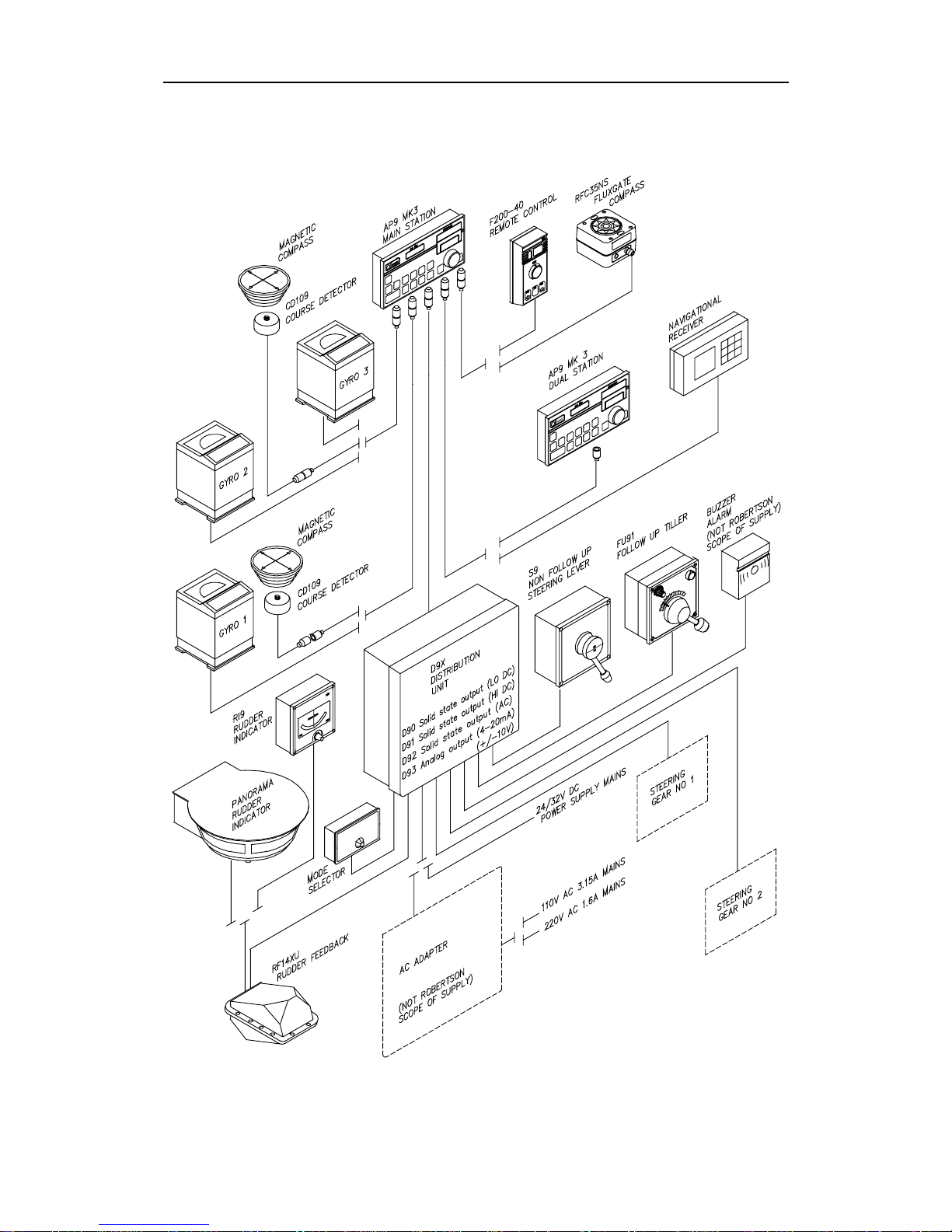
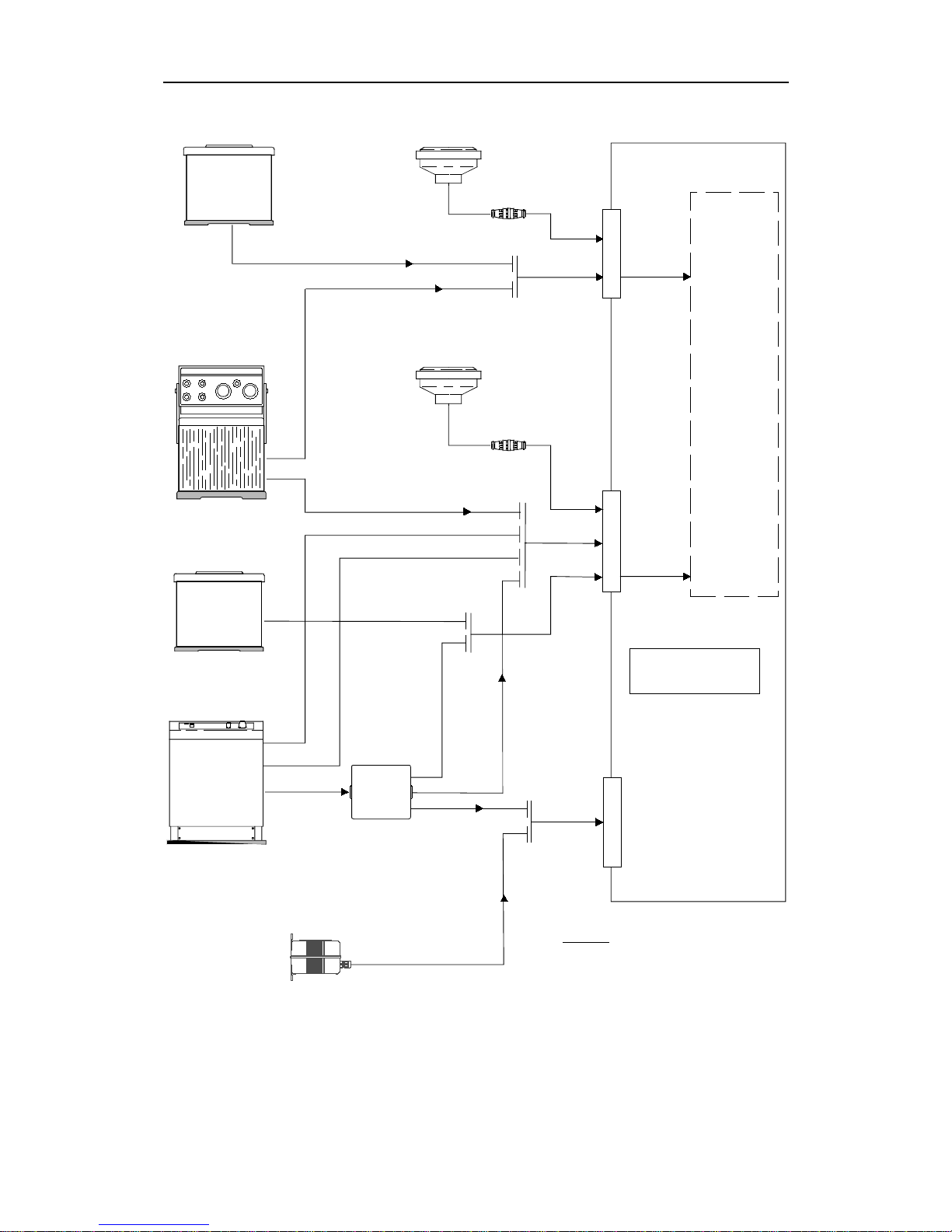
1.2 MK3 System Layout
The complete AP9 MK3 system layout is shown in Fig. 1-1
A number of configurations can be made from the complete system
layout, and certain standard systems are shown in separate figures.
The relationship between control signals, mode signals and the
different versions of distribution unit are shown in the standard
system drawings.
The combinations of heading sensors are shown in Fig. 1-5.
1.3 Options available with the standard system
The AP9 MK3 system has a series of options that can be specified,
allowing the autopilot system to be configured to suit virtually any
particular vessel.
Optional equipment:
• Dual station
This is a second control unit for remote control of the main station
functions
• Non Follow Up (NFU) steering lever with mode selector and lock
mechanism
• Follow up (FU) steering lever with mode selection
• Rudder angle indicators
• Watch alarm
• Thruster control/second parameter set; i.e. the ability to control
either a thruster or both the rudder and thruster simultaneously.
This option requires a special interface board in the Distribution
Unit.
Page 14
Robertson AP9 MK3 Autopilot
1-2 20169223D
For operation, technical specifications, installation and spare parts,
see the respective sections of this manual.
Fig. 1-1
AP9 MK3 System layout
Page 15
Introduction
20169223D 1-3
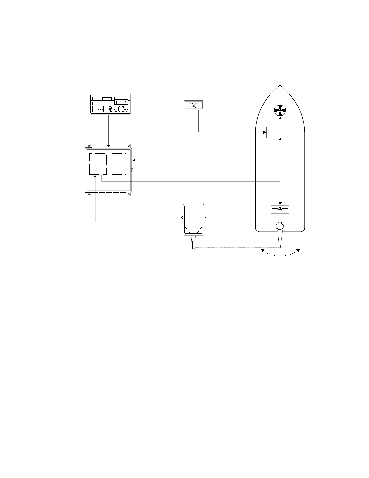
1.4 AP9 MK3 Standard System, On-Off Valves
Ref. Fig. 1-2.
The standard AP9 MK3 system consist of the following units:
• AP9 MK3 Control Unit P/N 20169199
Optional Gyro interface PCB P/N 20168316
• CD109 Magnetic Course Detector
(with tripod holder) P/N 20120861
• RF14XU Feedback Unit (with transm. link) P/N 22501647
• D9X Distribution Units:
Version D90 (19-40V DC, 3A solenoids) P/N 20125001
(Extra S.S.B. P/N 20125043)
Version D91 (110V DC, 1A solenoids) P/N 20125407
(Extra S.S.B. P/N 20125423)
Version D92 (110/220V AC, 1A solenoids) P/N 20125704
(Extra S.S.B. P/N 20125720)
Note that the standard
mains supply is 24V DC.
If AC mains is used, the
system must also include
an AC Power Adapter
(Not supplied by Simrad
Robertson AS)
Where the system shall
operate two sets of
solenoid valves, one
extra Solid State PCB
(S.S.B.) must be mounted
in the D9X Distribution
Unit (see above).
Interface to navigational
receiver is incorporated.
Fig. 1-2
Standard system with ON-OFF
valves
AP9MKII AUTOPILOT
NAV.RECEIVER
AP9 MK3
MAGNETIC COMPASS
CD109
GYRO-COMPASS
D9X
DISTRIBUTION
(D90/91/92)
AC
ADAPTER
24V DC MAINS
24V DC ALARM
"ON-OFF""ON-OFF"
TO INDICATORS
(VOLTAGE)
RF14XU
RUDDER
TRANSMISSION LINK
SOL.
VALVE
PUMP 1
SOL.
VALVE
PUMP 2
AUTOPILOT F.B.
FOR TWO PUMPS,
ADD EXTRA
SOLID STATE PCB.
110/220V AC
50/60Hz
(FREQUENCY)
Page 16
Robertson AP9 MK3 Autopilot
1-4 20169223D
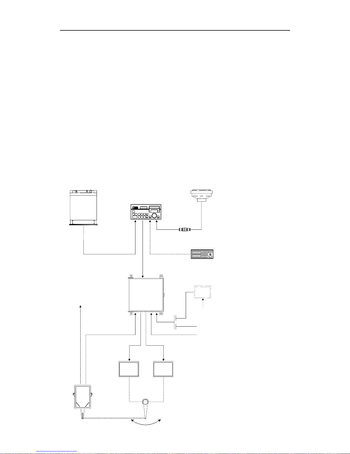
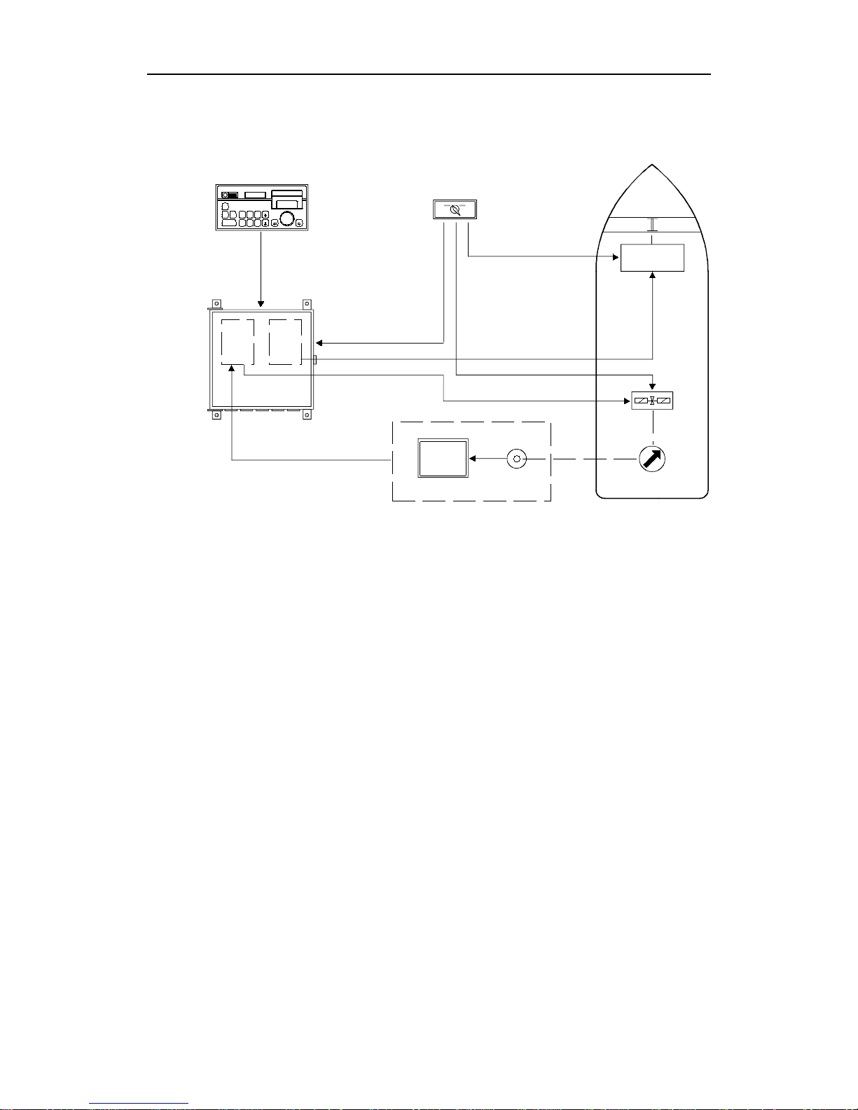
1.5 AP9 MK3 Standard System, Dual analogue output
The dual analogue system consist of the following units (Ref. Fig.
1-3.):
• AP9 MK3 Control Unit P/N 20169199
• Gyro Interface Board (Optional) P/N 20168316
• CD109 Magnetic Course Detector P/N 20120861
(with tripod holder)
• D93 Distribution Unit: P/N 20126009
Provides two galvanic isolated ±10V (adjustable)
or 4-20mA output signals
Note ! No autopilot feedback unit is required.
It is recommended to use a separate mode selector to provide changeover (c/o) signals to the respective steering gear electronic units. Th e
following functions can be included:
A: MANUAL - AUTO
B: MANUAL - PORT - STBD - BOTH
(Function to be specified when ordering)
Fig. 1-3
Standard system, ±10V
Dual Analogue
AP9MKII
AUTO PILOT
STEERING
GEAR
EL. 1
STEERING
GEAR
EL. 2
RUDDER RUDDER
FEEDBA C K FEEDBA C K
EXT. MODE SELECTOR
(OPTIONAL)
D9X
DISTRIBUTION UNIT
D93
POWER
ADAPTER
110/220V AC
50/60Hz
24V DC MAINS
24V DC ALARM
NAV. RECEIVER
MAGNETIC COMPASS
AP9 MK3
GYRO-COMPASS
CD109
T.B.
C/O
C/O
+/-10V
ANALOG
+/-10V
ANALOG
MODE
**
NOT ROBERTSO N
SUPPLY
*
Page 17
Introduction
20169223D 1-5
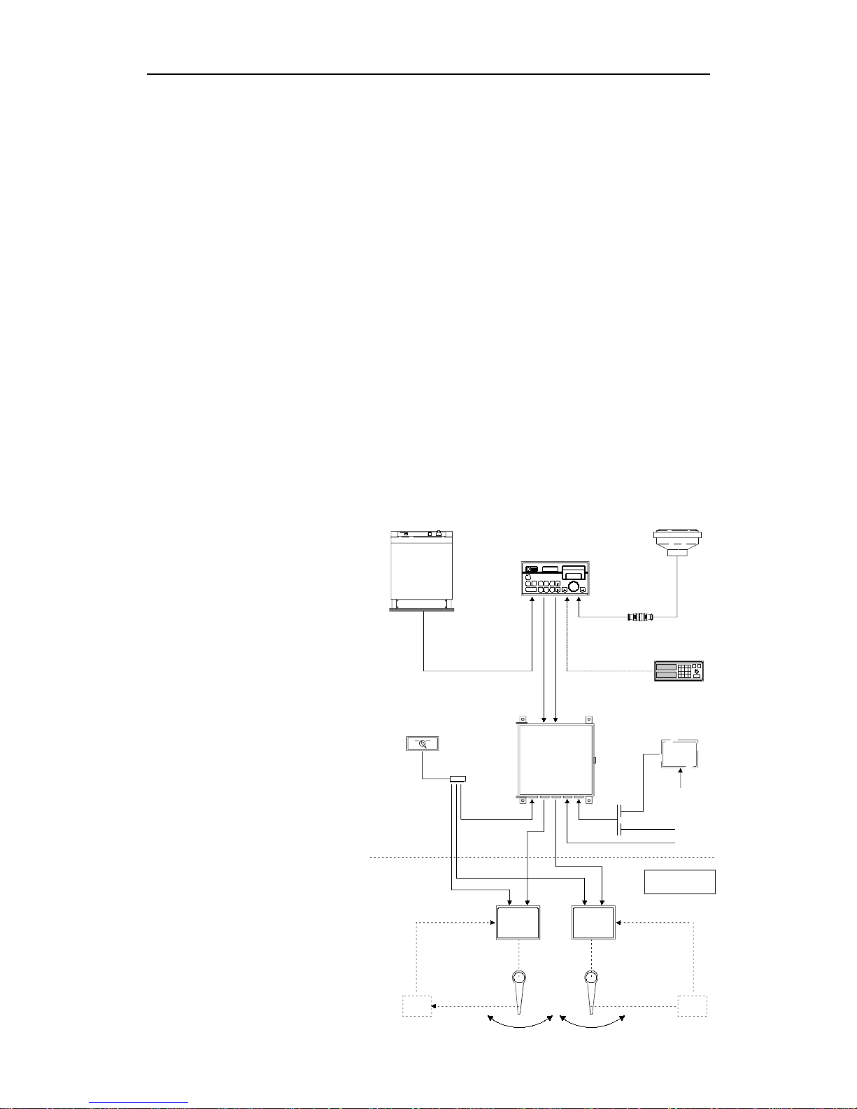
1.6 AP9 MK3 with analogue thruster control
Ref. Fig. 1-4.
The system consists of the following units:
• AP9 MK3 Control Unit P/N 20169199
Optional Gyro Interface Board P/N 20168316
• CD109 Magnetic Course Detector
(with tripod holder) P/N 20120861
• D9X Distribution Unit P/N 20126306
(Includes S.S.B.(s) or Dual Analogue PCB P/N as per D9X
depending on steering gear interface)
• Thruster Interface PCB P/N 20126017
(Replaces Interconnection PCB P/N 20125027
in D9X Distribution Unit)
• Thruster switch (RUDDER - THRUSTER) P/N 20168605
• RF14XU Feedback Unit P/N 22501647
(When connected to solenoid valves)
AP9M KII
AUTOPILOT
MAGNETIC COMPASS
AP9 MK3
NAV. RECEIVER
THRUSTER SWITCH
GYRO COMPASS
D9X
DISTRIBUTION
UNIT
FEED-
BACK
STEERING
GEAR
EL.
NOTE:
STEERING SYSTEM EITHER ON-OFF OR ANALOGUE.
FOR ANALOGUE, NO FEEDBACK IS REQUIRED FOR AUT OPILOT .
THR.
INT.
PCB
CD109
MODE
+/-10V ANALOG
NOTE
24VDC
MAINS
Fig. 1-4
Thruster control
Page 18

Robertson AP9 MK3 Autopilot
1-6 20169223D
1.7 Combinations of Heading Sensors
Ref. Fig. 1-5.
The AP9 MK3 Control Unit is designed to accept several types of
heading sensors. The sensors can be divided in three groups:
1. Gyro Compass
2. Fluxgate Compass (Recommended as monitor compass only)
3. Magnetic Compass (Recommended as monitor compass only)
GYRO COMPASS
To interface to SYNCHRO, GYRO EXCITED, A/P EXCITED or STEP
type gyro, the AP9 MK3 Control Unit must be equipped with the
Gyro Interface Board P/N 20168316.
Signal type Option al ha rdware
Synchro 11,8V l-l 400Hz Gyro Interface PCB
Synchro 20-115V l-l 50-60Hz, 400Hz Gyro Interface PCB
Step 6 step/degree Gyro Interface PCB
Sin/cos Not required
Serial Not required
Note ! Two SYNCHRO or two STEP signals can not be connected at the same
time. When using two gyrocompasses, one gyro must provide SYNCHRO
signal and the other gyro must provide STEP signal.
When using gyro with serial signal, no Gyro Interface Board is
required.
Notice that dual station system communication can not be made
when UART or NMEA serial line is used.
The Robertson RGC gyros can be connected according to the following
table:
Direct connection RGC Interface connection
RGC10 Synchro Serial, sin/cos, 6 step/degree
RGC11 RS422 Tokimec spes. Serial, sin/cos, 6 step/degree
RGC50 Synchro Serial, sin/cos, 6 step/degree
RGC12 Serial Serial, sin/cos, 6 step/degree
For details of gyro selection see page 5-58.
Page 19
Introduction
20169223D 1-7
SKR-82 GYRO
GYRO-COMPA SS
RGC GYRO
RGC
INT. FACE
ROBERTSON
RFC35NS
J2
SYNCHRO
MAGN.
GYRO
INTERFACE
BOARD
SYNCHRO
1:1
90:1
360:1
STEP
6 STEP/DEGREE
SERIAL
MAGN.
STEP
SIN/COS
(FLUXGATE)
J3
J5
AP9 MK3
CONTROL UNIT
SERIAL UART
SERIAL
UART
SIN/COS
GYRO-COMPA SS
SIN/
COS
1:1 SYNCHRO
110V 400Hz
(ONLY RGC10
AND RGC50)
MAGNETIC COMPASS
CD109
MAGNETIC COMPASS
CD109
SYNCHRO
SYNCHRO
NOTE:
THE GYRO INTERFACE
BOARD CAN NOT ACCEPT
TWO SYNCHRO OR
TWO STEP SIGNALS
SIMULTANEOUSLY,
ONLY ONE OF EACH.
STEP
STEP
SERIAL TOKIM EC
NMEA
Fig. 1-5
Heading Sensors
Page 20

Robertson AP9 MK3 Autopilot
1-8 20169223D
RGC Gyro with RGC Signal Interface Unit
When using an RGC gyro together with the RGC Signal Interface,
four options of connections are possible:
1. UART serial line, 20mA. (Identical to the SKR 82 serial line)
2. NMEA serial signal
3. Fluxgate sin/cos signal, identical to the Robertson fluxgate signal.
4. Step signal, 24V – 6 step/degree.
When using the fluxgate signal, select FLUXGATE compass.
When using step signal, select STEP SIGNAL.
See page 2-6 for compass selection.
RGC12 Gyrocompass
The RGC12 RS422 Tokimec special protocol or NMEA can be
connected directly to the AP9 MK3 without any Gyro Interface PCB.
FLUXGATE COMPASS
The AP9 MK3 is designed to accept fluxgate compass sin/cos signals,
using 2.5V DC as reference.
The Robertson type of Fluxgate Compasses, such as the RFC35NS
therefore interfaces directly to the AP9 MK3.
Note ! A fluxgate compass should only be used as a Monitor Compass.
Gyrocompass is always recommended as Main Compass.
For details, refer to page 5-10.
Page 21
Introduction
20169223D 1-9
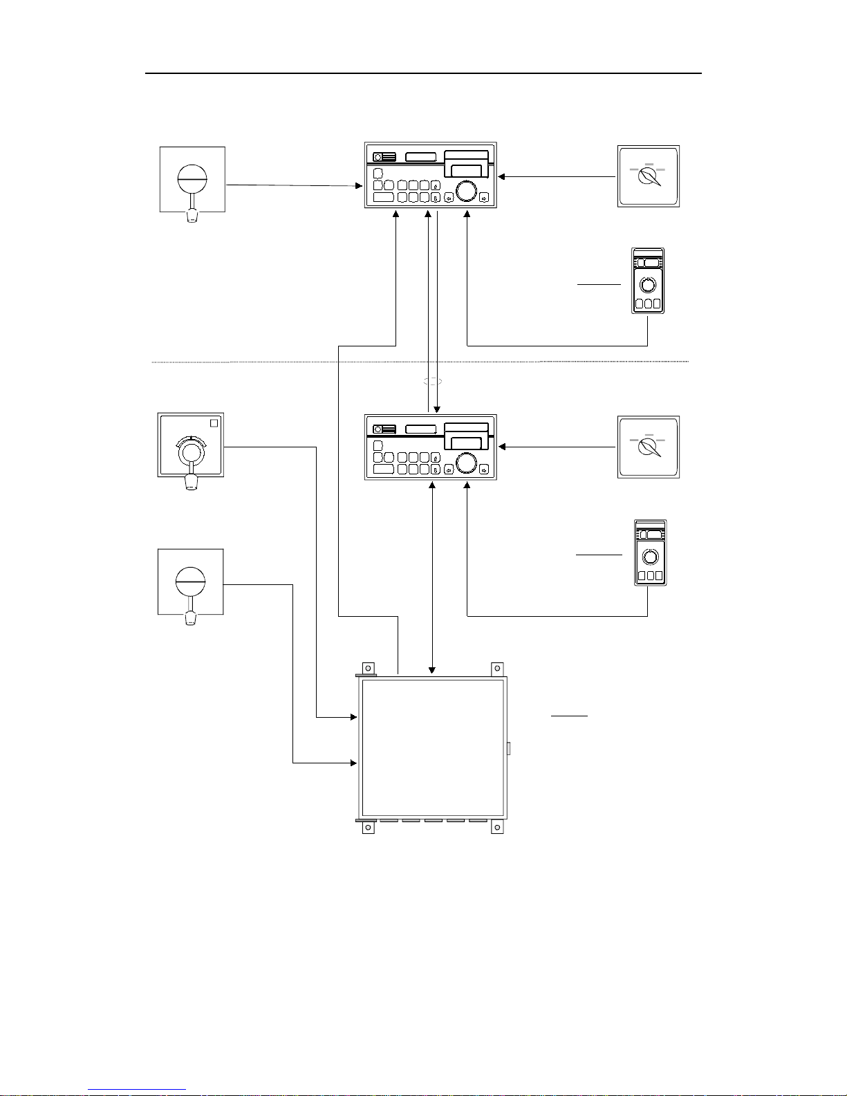
1.8 Dual Station
See Fig. 1-7
The AP9 MK3 Control Unit can also be used as a remote station,
communicating with the main station by serial lines.
The dual station system is designed to enable individual connections
of NFU levers, F200-40 remote controls and mode selectors. This
makes it possible to select mode and change parameters from the two
stations individually. FU levers can only be connected to the main
Control Unit via D9X.
Note ! Change of parameters except the selection of compass on one unit, will
change the same parameters on the other unit.
Parameter 2 option (Thruster function) can be selected individually
on the two units, but adjustment of parameters on one unit will
automatically change the same parameters on the other unit.
When a F200-40 Remote Control is connected, a mode selector must
have an "OFF" position to allow proper function of the F200-40.
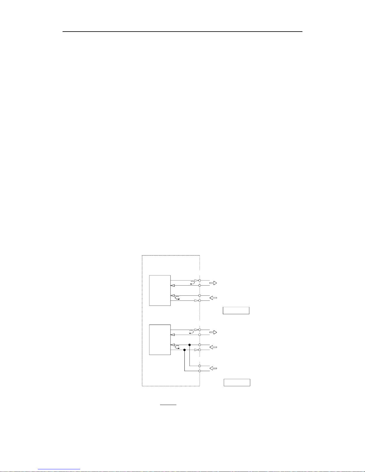
SERIAL LINES
The AP9 MK3 has several serial line connections.
As shown in Fig. 1-6, two input lines are in parallel, the "COMM.
LINE" and the "SERIAL HDG. DATA". This excludes the interface to
serial heading data when a dual station is used.
3
6
9
10
8
6
1
2
1
2
H
H
L
L
OUT
IN
B
OUT
IN
IN
SERIAL HEADING DATA
COMM. LINE
(DUAL ST./RMP)
COMM. LINE
(DUAL ST./RMP)
HEADING
NMEA (HDT/HDM)
NAV. RECEIVER
(NMEA)
AP9 MK3
CHANNEL A
CHANNEL B
NOTE: In Dual Station configuration, serial heading data
can not be connected to J3, 1-2.
H
H
L
L
OUT
IN
A
OUT
IN
J4
J4
J3
Fig. 1-6
Serial line connections
Page 22
Robertson AP9 MK3 Autopilot
1-10 20169223D
AP9MKII AUTOPILOT
AP9MKII A UTOPILOT
S9
NFU LEVER
AP9 MK3
REMOTE STATION
EXT. MODE SELECTOR
(OPTION)
F200-40
SEE N O TE
COMMUNICATION LI NES
D9X
DISTRIBUTIO N
UNIT
F200-40
SEE N O TE
EXT. MODE SELECTOR
(OPTION)
S9
NFU LEVER
FU9X
FOLLOW -UP
LEVER
AP9 MK3
MAIN STATION
PWR
NOTE:
WHEN A F200-40 IS
CONNECTED, T HE
MODE SELECTO R(S)
MUST INCLUDE AN
"OFF" POSITION.
Fig. 1-7
Dual Station System
Page 23
Introduction
20169223D 1-11
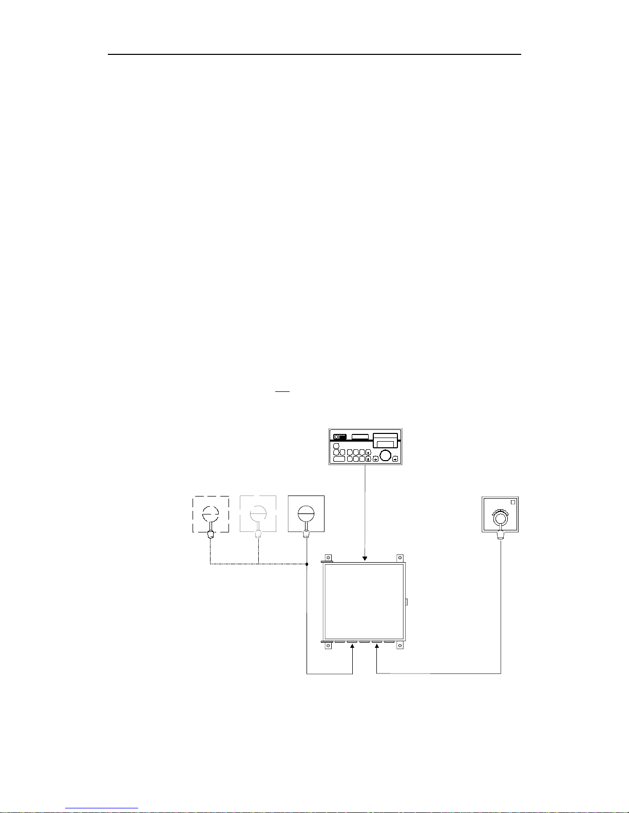
1.9 Connection of steering levers
As shown on Fig. 1-8., a number of NFU levers and a single FU lever
can be connected to the AP9 MK3 autopilot system.
The S9 NFU lever combines an "IN - OUT" function with the normal
PORT - STBD operation. The "IN - OUT" function can be combined
with the external mode-selection of the autopilot and this
automatically brings the autopilot to NFU mode when the S9 lever is
pulled out. The mode change has two alternatives:
A. Sets the autopilot to NFU mode when the S9 is pulled out. NFU
mode will remain when S9 is pushed in again. AUTOMATIC or
NAV to be selected on the control unit. For this alternative refer to
page 5-24.
B. Sets the autopilot to NFU-mode when the S9 is pulled out. Mode
will change back to AUTOMATIC or NAV when the S9 lever is
pushed in again. To obtain this function, the closing contacts if S9
no. A5-A6 is used to control the mode. Refer to page 5-21.
An unlimited number of S9’s can be connected in parallel.
Note ! It is also possible to add several FU-levers to an AP9 MK3 system by using
the FUA9X Follow-Up Amplifier instead of the D9X Distribution Unit.
Note ! NFU levers should not be used for analogue steering(
±
10V output).
AP9MKII AUTOPILOT
AP9 MK3
S9 S9
S9
(NFU)
FU9X
D9X
DISTRIBUTION
UNIT
ONE OFF
Fig. 1-8
NFU/FU Levers
Page 24
Robertson AP9 MK3 Autopilot
1-12 20169223D
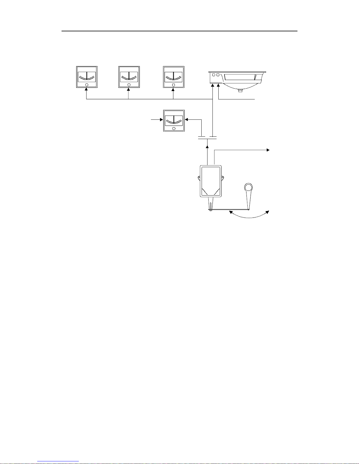
1.10 Rudder Angle Indicators
RI9
RUDDER
PANORAMA
NO.1
NO.2
NO.3
NO.4
24V DC
INDICATOR
SUPPLY
24V DC
INDICATOR
SUPPLY
FEEDBACK
TO AUTOPILOT
RF14XU
+/-45/60/70/90 DEGREE
FREQ.
3400Hz +/-20Hz/DEGREE
RI9
RI9
RI9
Fig. 1-9
Rudder Angle Indicators
Fig. 1-9 shows a typical Rudder Angle configuration. Number and
type of indicators varies from ship to ship.
The indicators must be of the "voltage" type, such as Panorama, RI40
and RI9. Installation instructions are supplied with the indicators.
Page 25
Introduction
20169223D 1-13
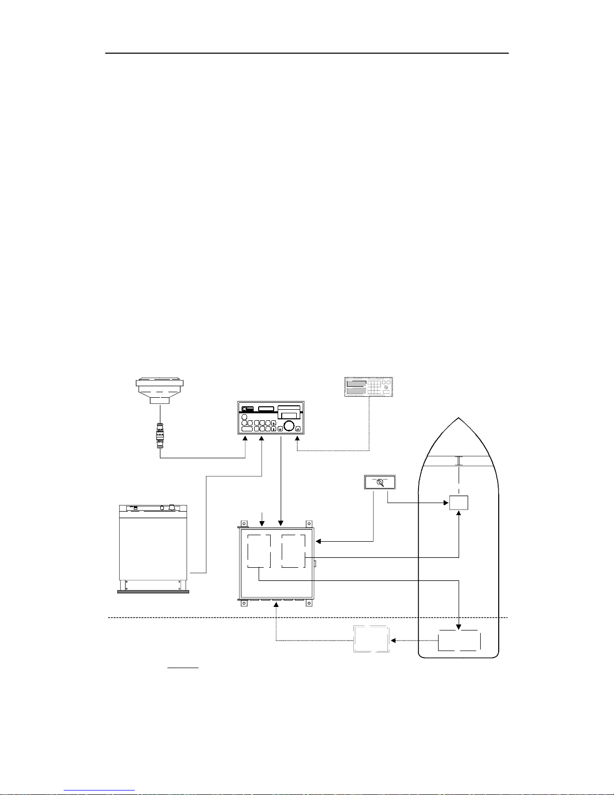
1.11 Special Applications
Example I:
AP9MKII
AUTOPILOT
THR.
INT.
PCB
SOL.
STATE
PCB
AP9 MK3
THRUSTER SELECTOR
SWICH
D9X
DISTRIBUTION
UNIT
RF14XU
RUDDER
SOLENOID
VALVES
MODE
+/-10V ANALOG
(VIA THR.INT.)
C/O SIGNAL
SOLENOID (ON/OFF) SIGNALS
THRUSTER
ELECTRONICS
Fig. 1-10
Special applications, Example 1
In this example the autopilot is interfaced both to a conventional
rudder system, using ON - OFF solenoid valves, and an azimuthing
bow thruster with ±10V as control signal.
The AP9 MK3 can provide different parameters f or the thruster and
the rudder control respectively, and the combination is determined
under the INFO loop 2 (Ref. page 2-9).
The combination shown above requires a Thruster Interface PCB to
provide the single ±10V analogue output, and a Thruster Selector
Switch to provide the change-over (C/O) signal to the thruster
combined with the mode control to the autopilot. The Thruster
Interface PCB, part no. 20126017 is mounted in the Distribution Unit,
and the solid state PCB must be specified according to the switching
voltage. (Ref. Standard System).
Page 26
Robertson AP9 MK3 Autopilot
1-14 20169223D
Example 2:
AP9MKII AUTOPILOT
AP9 MK3
THRUSTER SWITCH
SERVO
POT.
D9X
DISTRIBUTION
UNIT
U/X
CONV.
THR.
INT.
PCB
SOL.
ST.
PCB
C/O SIGNAL
C/O SIGNAL
ON-OFF SIG NAL
MODE
FEEDBACK
+/-10V SIGN.
FREQ. (X)
(U)
SOLENOID
VALVES
THRUSTER
ELECTRONICS
Fig. 1-11
Special applications, Example 2
The AP9 MK3 autopilot is also designed to operate a tunnel bow
thruster, with possibility to set deadband and thruster power in the
second parameter set.
The control signal is the ±10V analogue, generated via the Thruster
Interface PCB.
The shown configuration also includes a main propulsion azimuth
thruster, operated by ordinary ON-OFF solenoid valves.
A special feedback arrangement is required to replace the standard
RF14XU. It consists of a servo potentiometer and a voltage-tofrequency converter, to facilitate the installation of the mechanical
and electrical part of the feedback system. Contact Simrad for further
information
Page 27
Introduction
20169223D 1-15
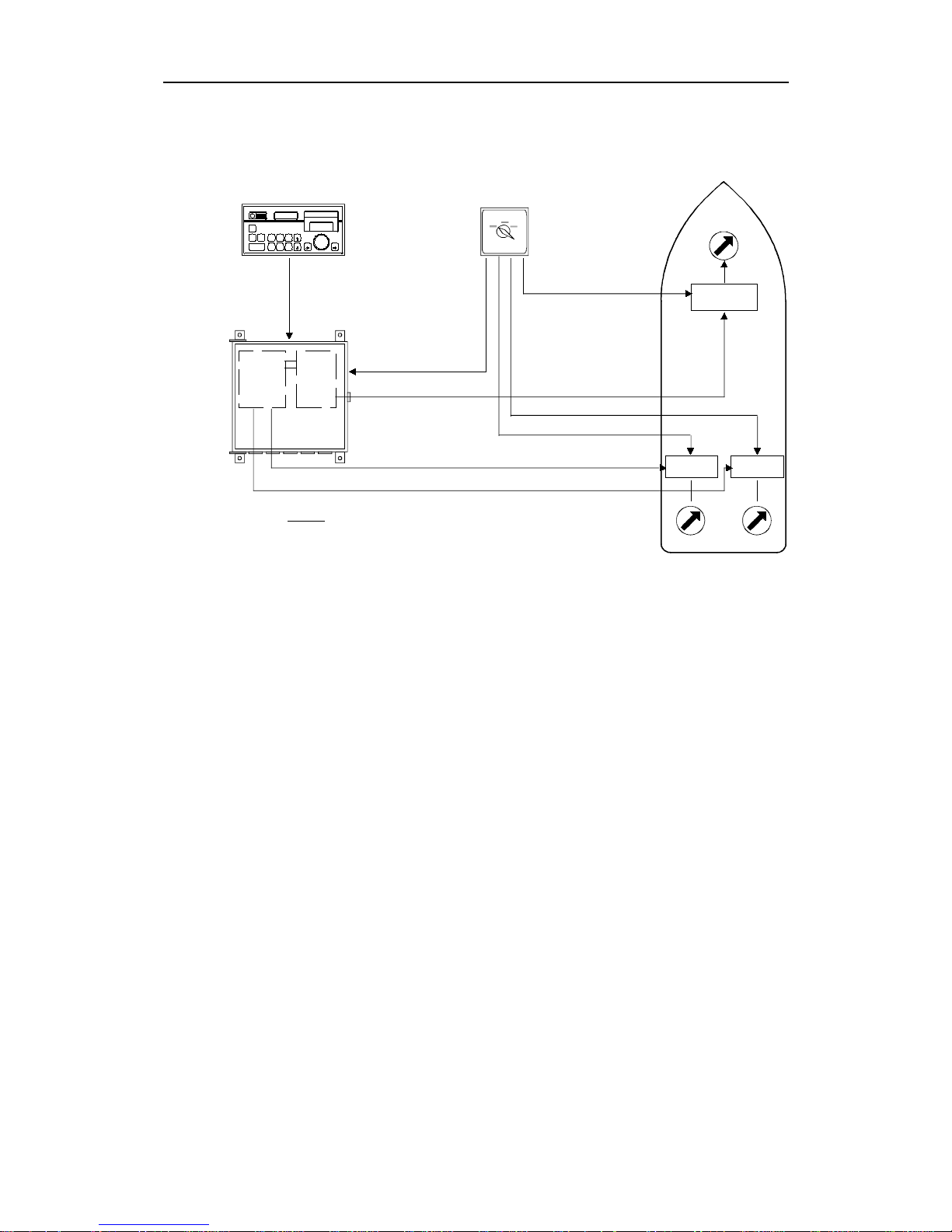
Example 3:
NOTE:
THE D94 CONTAINS ONE THRUSTER INTERFACE
BOARD AND ONE DUAL ANALOG PCB.
AP9MKII AUTOPIL OT
AP9 MK3
THRUSTER SELECTOR
(SPECIAL)
D94
DISTRIBUTION
UNIT
DUAL
ANALOG
PCB
THR.
INT.
PCB
BOW
THRUSTE R
AFT THRUSTERS
+/-10V
+/-10V
C/O SIGNAL
C/O SIGNAL
+/-10V
MODE
P
S
C/O SIGNAL
THRUSTER
ELECTRONICS
THRUSTER
ELECTRONICS
THRUSTER
ELECTRONICS
Fig. 1-12
Special application, Example 3
The AP9 MK3 autopilot system can provide three galvanic isolated
±10V outputs and be configured as shown in Fig. 1-12.
In this example the Distribution Unit is equipped with one Thruster
Interface board to control the bow thruster, and one Dual Analogue
PCB to control the two aft thrusters.
The Thruster Selector Switch is normally custom-made for each
individual system, and provides the change-over signals for the
thrusters, and the mode for the autopilot.
No Feedback Unit is required!
Thruster Selector Positions:
• MANUAL
• AUTO AFT (Aft Thruster)
• AUTO BOW (Bow Thruster)
FEATURES: First parameter set for synchronized operation of the
aft thrusters.
Second parameter set for the operation of the bow
thruster.
Page 28

Robertson AP9 MK3 Autopilot
1-16 20169223D
This page is intentionally left blank.
Page 29
Operation
20169223D 2-1
2 OPERATION
* * * * * * *
NAV
HELMS-
MAN
AUTO COMPASS
SELECT
ILLUM
COUNTER
RUDDER
RUDDER
INFO
WEATHER
OFF
INCREASE
DECREASE
PORT
STBD
AUTOPILOT
AP9 MK3
ALARM
RESET
R
Mode selection Parameter setting Course selection
Fig. 2-1
AP9 MK3 Front panel
2.1 General
AP9 MK3 autopilot is operated by means of keypad push buttons on
the front panel. The buttons are back lighted, activated buttons being
brighter than the others.
Course selection is made by the rotary Course Selector Knob. Course
adjustments in steps of one degree can be achieved by the port or
starboard push buttons.
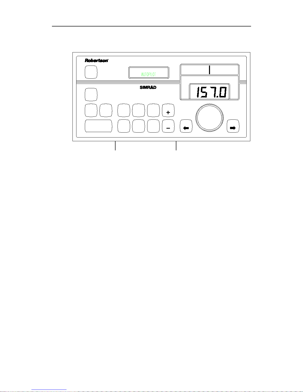
The front panel has three LCD displays, referred to as the
information display (left side), bargraph display (upper right) and
the course display. An alarm buzzer and an alarm reset button is also
on the front panel.
A few simple operations like pressing a button and/or turning the
Course Selector Knob is required in ordinary use of the autopilot. All
other instructions and data required for the operation are stored in
the autopilot upon delivery.
2.2 Front Panel
The front panel is divided into three sections: Mode selection,
Parameter setting and Course selection (Fig. 2-1).
Page 30

Robertson AP9 MK3 Autopilot
2-2 20169223D
2.3 Mode selection
Together with the OFF-button and the 3 mode buttons, this section
also contains an alarm buzzer and ALARM RESET-button.
HELMSMAN (Power ON)
The HELMSMAN button serves two purposes. It switches on the
autopilot and selects manual steering mode. In this mode the course
display gives a digital read-out of compass heading, while the vessel
can be steered manually by helm or steering lever(s).
AUTOPILOT
The AUTOPILOT-mode is used under normal conditions when the
boat is steered automatically on a pre-set course.
When the AUTOPILOT-button is pressed, the autopilot selects the
current vessel heading as "course to steer".
Any difference between course to steer and the vessel's actual
heading will then be shown as a bargraph in the bargraph display.
One bar equals one degree.
The autopilot uses the activated heading sensor unit, selected from
the COMPASS SELECT button to calculate the difference between
course to steer and actual ships heading. Rudder command signals
are then based on steering parameter settings.
Rudder commands are indicated by an arrow to left or right in the
bargraph display depending upon which direction the autopilot
commands the rudder to move. These arrows do not appear when
the autopilot output signal is analogue voltage. The “Debug” rudder
angle may show a random number as no rudder feedback is
connected.
For the ±10V analogue control signal, a separate rudder control
system moves the rudder to match the rudder angle command.
NAV. MODE
NAV.-mode is used when a navigation receiver is connected to the
autopilot for automatic "waypoint" steering.
When the NAV-mode is selected, the AP9 MK3 automatically
monitors the signals from the navigation system. If the signals are
absent or in a wrong data format, an alarm will be given to alert the
operator. See page 2-15: Navigational Steering.
OFF
The autopilot is switched off by pressing the OFF-button for 2
seconds, during which time the alarm will sound. The alarm ceases
Page 31

Operation
20169223D 2-3
when the AP9 MK3 is switched off. If the OFF-button is released
before two seconds have elapsed, the autopilot will continue to
operate as before and the alarm signal is automatically reset.
Rudder commands will stop as long as the OFF-button is pressed. All
pre-set parameters in the autopilot are stored while the unit is
switched off.
ALARM
The acoustic alarm is reset by pressing the alarm reset button.
Alarm messages shown on the information display are described on
page 2-25. Fault Warnings.
Thruster/rudder parameters
When the autopilot is connected to a thruster in addition to the
rudder, a separate Thruster Switch will enable a second set of
parameters to control the thruster. Whenever the Thruster Mode is
selected, all parameters can be individually set for optimal
performance from the thruster, while the parameters used for
Rudder-steering are saved and resumed when the Thruster Switch is
set to "RUDDER".
2.4 Parameter setting
Note ! When the "RUDDER" and "WEATHER" buttons are pressed
simultaneously, IDEAL parameters are recalled, provided the parameters
have been stored earlier (during sea-trial). See installation section, page 5-
69.
General
The middle section of the AP9 MK3 control unit contains 8 push
buttons and an information display. The display shows selected
mode, deviation from set course, parameter settings and other user
information. The text in the information display can be shown in one
of four selectable languages: English, French, Spanish or Norwegian
(see page 5-40).
When RUDDER, COUNTER RUDDER, WEATHER or ILLUM
buttons are pressed, the display shows which button has been
activated and to what level the value has been set by the number of
bars as well as in plain figures. The displa y returns to normal readout, showing the selected mode one minute after the last press on one
of the buttons.
The ability of the autopilot to steer a vessel is not only dependent
upon the control logic used, but also the hull shape of the vessel, the
steering gear and the weather conditions. The AP9 MK3 can be set up
to steer almost any vessel. During normal day to day operation
Page 32

Robertson AP9 MK3 Autopilot
2-4 20169223D
RUDDER, COUNTER RUDDER and WEATHER can be easily
adjusted from the front panel. In addition the autotrim can also be
adjusted, but should be permanently set during initial sea trials. The
autotrim parameter is accessed using the INFO button.
Switch ON
The autopilot is switched on by pushing the HELMSMAN button
(The switch can be sensed by the finger!)
The autopilot will acknowledge with a short audible "blip" and
confirms initialisation by showing:
SOFTWARE: mk3 V1R4
INITIATING
or
SOFTWARE: mk3 V1R4
CHECKING COMPASS
If the serial compass switch is ON the text ‘CHECKING COMPASS’
is displayed while type of serial compass is detected.
If serial compass data is not connected the alarm text ‘SERIAL COMP
FAIL’ is displayed and serial compass is removed from sensor setup.
If serial data has wrong polarity or has UART format, then the text
‘Uart OK’ or ‘Chg HiLo’ (Change Hi-Lo) is displayed.
After a few seconds Helmsman will be shown in the information
display:
* * * * * * *
HELMSMAN
If the autopilot is connected to a gyrocompass where the gyro
heading needs to be set, the display will show at switch on:
GYROADJUST
PRESS INC / DEC
Press the INCREASE or DECREASE button until the autopilot
display shows the same heading as the gyrocompass.
Then press the HELMSMAN button and the display will show:
* * * * * * *
HELMSMAN
Note ! If another language is preselected, the display may show:
TIMONEL (Spanish), MANUEL (French) or RORMANN
(Norwegian)
To change the language, do the following:
Page 33

Operation
20169223D 2-5
• Press INFO and keep it pressed.
• Press WEATHER
• Release WEATHER
• Release INFO.
The INFO display will show one of the following:
ENGLISH, ESPANOL (Spanish), FRANCAIS (French) or NORSK
(Norwegian)
The language can now be selected and stored by pressing either
INCREASE or DECREASE. The INFO display will fall back to
HELMSMAN approx. 1 minute after the last operation of
INCREASE/ DECREASE, or immediately by pressing HELMSMAN.
HELMSMAN
This is the "stand-by" mode for the autopilot. When this mode is
selected, the autopilot is passive and manual rudder operation, either
by steering wheel or Non Follow Up (NFU) levers, is made.
The Heading Display will show the actual course with resolution of
one tenth of a degree, operating as a heading repeater. The Bargraph
Display will show one single vertical line, indicating zero heading
error.
AUTOPILOT
When clear of obstacles and in open waters, steer the vessel on course
and press the AUTOPILOT button.
The display will now show:
* * * * * * *
AUTOPILOT
and the autopilot will automatically keep the vessel on course.
INCREASE- and DECREASE-buttons
These buttons are used to alter various settings. Each time one button
is pressed, the value shown on the information display, will increase
or decrease by one unit. The value is also shown as a graphical bar. If
the button is kept pressed for more than two seconds, the value will
automatically count up or down until the button is released.
ILLUM
The ILLUM button is used to adjust the illumination of buttons and
displays. .
Page 34

Robertson AP9 MK3 Autopilot
2-6 20169223D
• To adjust the illumination, first press the DIMMER button, than
the INCREASE or DECREASE button. In the information display a
number and a bargraph represent the brightness level.
COMPASS SELECT
The autopilot is capable of reading two heading sensors
simultaneously: Main (steering) compass and monitor (comp.
difference) compass.
If only one compass is connected, this will always be the main
compass. The autopilot shows the main compass heading in
HELMSMAN-mode and selects this heading as set course in
AUTOPILOT mode. The difference between the set course on the
autopilot and the main compass heading is known as the off course
deviation.
The autopilot monitors the off course deviation and if it exceeds the
selected off course limit, an off course alarm will sound. (See page 536 for selection of off course limit).
If more than one compass is connected, one is selected as main
compass and one as monitor compass. The autopilot now monitors
the heading difference between the main compass and the monitor
compass. The heading difference alarm is given when the differen ce
exceeds the off course limit and thus the heading difference alarm
also acts as an additional off-course alarm.
Press the COMPASS SELECT button once and the information
display shows the selected main compass. By then pressing the
INCREASE or DECREASE button another compass can be selected as
main compass from one of the compasses connected to the autopilot.
Press the COMPASS SELECT button a second time and the
information display shows the selected monitor compass. Another
monitor compass can be selected (not the one selected as main
compass) by using the INCREASE or DECREASE buttons. The
monitor compass can also be switched off by the same buttons.
RUDDER
When the RUDDER button is pressed, the Information Display
shows selected RUDDER value. The RUDDER value sets the ratio
between rudder angle and heading error (p-factor).
Example: If RUDDER is set to 1.0 and there is a heading error of 2
degrees, the rudder angle will be 2 degrees. (Heading error x
RUDDER value = rudder angle).
The correct RUDDER setting is dependent upon the size and speed of
the vessel. The RUDDER value should increase with decreasing
speed.
Page 35

Operation
20169223D 2-7
Examples of incorrect RUDDER settings:
Fig. 2-2
Rudder settings
A value which is too low gives relatively large and slow oscillations
(s-ing) around set course, and several rudder commands are given in
the same direction before the vessel is back on course.
A value which is too high will give quick and increasing oscillations
(s-ing) around set course.
The correct setting of RUDDER will be approximately in the middle
of the settings described in Fig. 2-2
Press RUDDER, thereafter INCREASE or DECREASE for required
amount of rudder.
Range: 0.1 - 3.3.
Recommended start value: 0.6 - 1.5.
WEATHER
The WEATHER setting determines the number of degrees the vessel
may fall off the set course before any response is given to the rudder.
In calm weather it should be set to OFF which means that
theoretically the autopilot allows no deviation from set course. The
WEATHER value should be increased with increasing sea state. This
will cause the sensitivity to be decreased such that the vessel has to
fall off course with the number of degrees selected by the Weather
setting before a rudder command is given. The amount of rudder is
calculated by the heading error exceeding the set limit, multiplied
with the p-factor. This will prevent big rudder amounts and reduce
rudder activity.
In conditions where active steering is required, (e.g. following sea
condition), the value should be reduced.
Press WEATHER, thereafter INCREASE or DECREASE for required
sensitivity.
Range: OFF - 8°. (OFF is max. sensitivity).
Recommended start value: OFF - 3°.
Too little rudder
Too much rudder
Course to steer
Course to steer
Page 36

Robertson AP9 MK3 Autopilot
2-8 20169223D
COUNTER RUDDER
The COUNTER RUDDER
serves two purposes, firstly
to give a smooth transition
to a new heading after a
major course change has
been made, and secondly
to enable the autopilot to
stabilize the vessel on a
straight course. The
steering characteristic of
the autopilot is determined
by the RUDDER and the
COUNTER RUDDER
adjustment.
The effect of the Counter
Rudder is partly determined by the selected Turn
Rate, hence tuning the
Counter Rudder effect also
involves the Rudder
Control.
A too low value results in an overshoot past the new heading and it
takes a long time before the new heading is stabilized.
A value that is too high results in an over correction followed by a
small overshoot past the new heading, and the vessel then tends to
oscillate around the new heading. A typically symptom here is an
over active-rudder.
Range: 0 – 8.0
Recommended start value: 0.6
Page 37

Operation
20169223D 2-9
INFO
The INFO button is used to call up a number of parameters and oth er
information.
The INFO loops can be entered in any autopilot mode. No change
will be made unless the INCREASE or DECREASE button is pressed.
The parameters are divided in two loops, one for the often used
parameters and one for seldom used parameters. The two loops are
entered differently and Loop 2 is mainly for installation set-up.
For detailed description of functions, see page 5-33. Information and
Debug loops.
INFO loop 1:
INFO loop 2:
• Rate of turn or Radius steering • Language
• Turn Rate/Radius • Deadband
• Rudder Limit • Minimum Rudder
• Off course • Serv. speed
• Autotrim • Speed sens.
- Nav. Filter *
• Minimum radius
- Nav. Gain *
• Thruster function
- Nav. Trim * - Only Thruster
• Gyro adjust **
- Only Rudder
• Comp. diff. ***
- Rudder + Thruster
- Thruster deadband
- Minimum thrust
• FU/A Scale
• Maximum rudder limit
• Navigational Mode
- Ecdis
- Priority
- XTE
- CTS
• 1/sec. out
- 5/sec out
• Software version/Runtime
* Only when Nav. Steering is selected.
** Only when step gyro or synchro is selected, not 1:1.
*** Only when two compasses are connected.
To escape from the INFO loops, press any mode or parameter button.
Note ! The INFO display will fall back to show the autopilot mode approximately 1
minute after the last entry of any parameter.
Page 38

Robertson AP9 MK3 Autopilot
2-10 20169223D
Operation, INFO loop 1
Press the INFO button. For adjustment of each parameter use
INCREASE or DECREASE button.
IIIIIIIIIIIIIII
AUTOTRIM 0.5
Press
INFO
III
TURNRATE 40°/m
III
RADIUS nm. 0.15
Press
RATE oT STEERING
CHANGE? INC/DEC
RADIUS STEERING
CHANGE? INC/DEC
Press
IIIIIIIIIIII
OFFCOURSE. L 10°
IIIIIIIIIIIIIIIIIIIIIII
RUDDER LIM. 15°
Press
Range: 1°/min - 360°/min.
Note: The range is limited by "min
radius" val ue in INF O LOO P 2.
Recommended: 40°/min
Range: 0,01 nm - 10 nm
Note: The range is limited by "min
radius" val ue in INF O LOO P 2.
Recommended: 0,1 nm
Press INC or DEC to alter between
ROT and Radi us st eer ing .
This rudder limitation setting is only
active during autosteering on straight
courses, NOT course changes.
Range: 1° - 85°
Recomme nd ed : 15°
Range: 3° - 35°
Recomme nd ed : 10°
(First display rea dout depends on what has been selected by
"Rate of turn (RATEoT) steering /Radius steering", see next parameter.)
Press
Range: OFF - 3,2
Recomme nd ed: 0,5
INFO
INFO
INFO
INFO
Page 39

Operation
20169223D 2-11
COMP. DIFF. 5°
PRESS INC.
IIIIIIIIIIIIIII
NAV. FILTER 1.1
IIIIIIIIIIIIIII
NAV. GAIN 1.0
IIIIIIIIIIIIIII
NAV. TRIM 180s
Press
INFO
INFO
INFO
Press
Press
Only if NAV is selected
and CTS is NOT selected
Range: 1. 1 - 2.5
Recommended: 1.1
Range: OFF - 3,2
Recommended: 1.0
Range: 100s - 1600s
Recomme nded: 180s
Press INC to zero-set the relative
difference between the two
compasses. The a ct ual difference i s
then show n in the di splay.
INFO
Press
Next press repeats the INFO loop 1
INFO loop 2
(For detailed description, see Sea Trial, page 5-62)
To enter this loop, do as follows:
• Press the INFO button and keep it pressed
• Press and release WEATHER button
• Release the INFO button
The display will now show:
* * * * * * *
ENGLISH
This is the language parameter. Use INCREASE/DECREASE to select
the required language. The different options are:
ENGLISH – FRANCAIS – ESPANOL – NORSK
Page 40

Robertson AP9 MK3 Autopilot
2-12 20169223D
IIIIIIIIIIIIIII
SERV. SP 18 Kn
Press
Press
Determ i nes the de adband fo r t h e
feedback loop (rudder hunting)
and also the heading sensitivity
of the autopilot.
Range: 0,2° - 3,4°
Recomme nded: 0,6°
Range: OFF - 10°
Recommended: OFF - 2°
Press
Range: 3 kn - 70 kn
Recommended setting: Ship's cruising
speed.
Press
INFO
INFO
INFO
III
MIN. RUDD 1.5
III
DEADBAND 0.6
Sets the autopilot speed re fe r ence
to the ship's service speed.
Determines the minimum amount
of rudde r as first comm and.
IIIIIIIIIIIIIII
SPEED SENS 0.33
Range: OFF - 1.92
Recomme nded: 0.36
INFO
This se tting scal es the amount of
rudder for speed change (lower
speed, more rudder!)
Press
IIIIIIIIIIIIIII
MIN RADIUS 0.05
Range: 0.01 - 1.10 nm.
Recomm e nd ed : Sh i p de pendent
INFO
This parameter limits the maximum
allowed turnrate setting or the minimum
allowed turn radius that can be set by the
Rate of Turn or Radius steering, selected
in Info loop 1. The setting also depends
on the service speed of the vessel. The
lower speed, the higher turn rate can be
set.
THRUSTER FUNC.
RUDDER+THRUST
IIIIIIIIII
FU/A SCALE: 45°
Range: 45° - 60° - 70° - 90°
Recommended: Set to relevant rudder
scale.
Determines the scaling of the
follow up function.
IIIIIIIIII
MAX RUDDLIM: 44°
Range: 26° - 90°
Recommended: Appr. 5° le ss than
max rudder tr avel.
Sets the absolute maximum
rudder deflection.
Press
INFO
Press
INFO
The thrus ter param eters only appear
if J4, 11-13 "Thruster Ident" on the
control unit are connected (via a switch).
See separate de sc ription .
Page 41

Operation
20169223D 2-13
NAVMODE=PRIORITY
CHANGE? INC/DEC
Range: Priority-XTE-CTS-ECDIS
Recommended: Priority (unless
ECDIS is used)
Selects the Nav. mode function
Press
INFO
1/SEC OUT FREQ.
CHANGE? INC/DEC
Range: 1/sec - 5/sec
Recommended: Refer to equipment
to be interfaced.
Determines the NMEA output rate.
Press
INFO
OFFSET = XXX°
FLUXGATE COMP
Only shown if signal is present on sin/co
s
input or at serial HDM input.
Used when fluxgate compass is
selected as steering compass.
Press
INFO
The next press repeates the
loop, starting with language.
SW ver. mk3 V1R4
RUN: 2d 2h
Displays software version and
runtime in days and hours when in
automatic mode.
Press
INFO
Page 42

Robertson AP9 MK3 Autopilot
2-14 20169223D
Thruster Function
THRUSTER FUNC.
RUDDER+THRUST
Range: OFF - 32°
Recommended: 5°
Press
INFO
INFO
III
THRUST DB 5°
INFO
III
MIN THRUST 25%
INFO
THRUSTER FUNC.
ONLY T HRUSTER
INFO
III
THRUST DB 5°
INFO
III
MIN THRUST 25%
INFO
INC
DEC
THRUSTER FUNC.
ONLY RUDDER
* PARAM SET 2 *
HELMSMAN
INC
DEC
IIIIII
FU/A SCALE: 45°
IIIIII
MIN RADI U S 0.05
INC
DEC
Range: OFF - 10 0%
Recommended: 25%
Range: OFF - 32°
Recommended: 5°
Range: OFF - 100%
Recommended: 25%
The thruster parameters only app ear if
J4, 11-13 "Thruster Id ent" on the control
unit are connected (via a swit ch).
Note:
Thruster deadba nd.
Min. amount of thrust.
Thruster deadband.
Min. amount of thrust.
The "Param set 2" will appear
in the display af ter one minute
or immediately when escaping
the loop by pushing an ot he r
button, e.g. Rudder.
See Parameter 2 option, page 5-31
Page 43

Operation
20169223D 2-15
2.5 Course selection
The course selector section on the autopilot consists of a bargraph
display, a digital heading display, a course selector and two course
adjustment buttons, PORT and STBD.
The bargraph display operates in two modes, AUTOPILOT and
NAVIGATION-mode, displaying in degrees the difference between
actual vessel heading and course to steer. On the display each "bar" is
equal to one degree, and the range is 20 degrees to port and
starboard. An arrow on each side indicates starboard and port rudder
commands.
Note ! No arrows for analogue signal output.
In HELMSMAN mode the digital heading display gives a read-out of
actual ships heading, while in AUTOPILOT and NAVIGATION
modes the read-out is course to steer.
The Course Selector is used for major c ourse c ha nges in A UTOP ILOT
mode. To activate the knob it must be pressed down and released. If
the knob is not turned within 10 seconds, it has to be pressed again.
Clockwise turns gives a starboard course change and vice versa. One
revolution on the course selector knob is equal to a 60 degree course
change.
The PORT and STBD push buttons are for minor course adjustments,
pressed once gives a one degree course change in the appropriate
direction.
These two buttons and the course selector are only active in
AUTOPILOT mode.
Note ! When making course changes by the push buttons the TURNRATE
function is not activated.
2.6 Navigational steering
General
Navigational steering should be used in open waters only.
Navigational steering is based upon signals taken from Loran C and
GPS Nav. receivers. The signals are called Cross Track Error (XTE)
and Bearing waypoint-waypoint (BWW), termed course to steer
(CTS).
When cross track steering is used, the information display gives a
read-out of actual cross track error in thousandths of a nautical mile
(.001). The XTE signal changes the set course to keep the vessel on
track.
AP9 MK3 can operate in a (CTS) mode where the bearing to the
waypoint is defined to be the course to steer by the autopilot. The
information display gives bearing to waypoint, elapsed time since
Page 44

Robertson AP9 MK3 Autopilot
2-16 20169223D
last update and the amount of course change. If a change of more
than 10 degrees is commanded, the alarm will sound and the
ALARM RESET button has to be pressed to acknowledge the course
change. The plain CTS mode is rarely used today after the GPS has
replaced the Transit system.
For receivers with NMEA 0183 format that outputs both the cross
track error (XTE) and bearing waypoint-waypoint (BWW), e.g. an
APB sentence, the autopilot can operate in the priority mode (also
called mixed mode) utilizing both signals.
Note ! The Course Change knob and buttons are disabled when operating the
autopilot in NAV. mode.
Steering by XTE to waypoint
When the autopilot is using XTE, the set course is automatically
adjusted in order to keep the vessel on a straight track between two
waypoints. Satisfactory steering depends upon good reception
conditions and correct adjustment of the autopilot.
During poor reception conditions, the receiver transmits an alarm
warning which activates the alarm circuit in the autopilot. The set
course reference is not updated until the reception conditions
improve. See Fault Warnings on page 2-25.
Make the following check before using navigational steering:
1. Set the Nav. receiver to calculate the bearing from present position
to a waypoint.
2. Steer the vessel by hand on the calculated bearing and select
AUTOPILOT-mode.
3. Let the autopilot steer the vessel for a period of about 2 minutes to
settle on the new course.
4. Make a starboard course change of 5°, by pushing 5 times on
STBD button and check that a course track error is built up on the
navigation receiver showing that the vessel is located to the right
of the bearing line.
5. Repeat step 4 with a 10° course change to port and check that the
vessel moves to the opposite side of the bearing line.
When the autopilot is performing satisfactorily in AUTO-mode, use
the following procedure:
1. Enter the desired bearing line(s) to the Nav. receiver using the
present position and the first waypoint or destination. Distance
between waypoints should be of minimum 1 n.m. Otherwise there
may not be sufficient time for the system to calculate the XTE, and
for the autopilot to alter the course and bring the vessel onto the
bearing line again.
Page 45

Operation
20169223D 2-17
2. Read the calculated bearing to waypoint from the Nav. receiver.
3. Set the course to the waypoint showed on the navigation receiver.
Before going to step 4, ensure that the XTE is within 0.1 n.m. to
avoid a hazardous course change when selecting NAV-mode.
4. Select NAV-mode on the AP9 MK3. The autopilot now
automatically changes the set course to reduce the Cross Track
Error (XTE) to zero. The information display shows the n umber of
degrees the autopilot has changed the set course, and the XTE in
1/1000's of a nautical mile. Note that the display read-out will be
delayed, depending upon the NAV. FILTER setting.
Note ! The accuracy of the autopilot depends on the accuracy of the GPS and it’s
output.
Example:
NAVIGATING
05 XTE = R0.021N
R indicates that the vessel is located to the right of the bearing line,
and L indicates to the left of the bearing line.
05 is the number of degrees course change relative to initial set
course. As the vessel approaches the bearing line, the correction
value decreases and when the vessel is on track, the information
display shows:
NAVIGATING
00 ON TRACK
5. As the vessel gets within the arrival circle set on the navigational
receiver, or as the vessel passes the perpendicular line to the
waypoint, the receiver transmits a "data not valid" signal to the
autopilot. An audible alarm will then activate and the course to
steer will no longer be updated.
To proceed to the next waypoint, the procedure should be repeated
from step 2 onwards.
Procedure:
• Reset the alarm on the autopilot and navigational receiver.
• Select "AUTOPILOT" mode on the autopilot.
• Use Course Change knob/buttons on the autopilot and to
set the new course given by the Nav. receiver.
• Press "NAV"
Page 46

Robertson AP9 MK3 Autopilot
2-18 20169223D
Priority mode (APB sentence)
NAV.RECEIVER
ACCEPT CHANGE
Y:RESET N:AUTO
WAYPOINT 3
WAYPOINT 2
WAYPOINT 1
INFO DISPLAY
INFO DISPLAY
INFO DISPLAY
05°
BEARING LINE
XTE= R0.02NM
R RIGHT
L LEFT
RESET
ALARM
NAVIGATING
05 XTE = R0.021N
NAVIGATING
00 ON TRACK
Note ! The waypoint arrival warning will depend on the arrival zone setting on the
navigational receiver.
The AP9 MK3 uses bearing waypoint – waypoint as the initial
heading reference. The XTE is used to update this heading reference
in order to minimise the XTE.
When arrival circle for the next waypoint is reached, the ACCEPT
CHANGE alarm will start.
If the turn is accepted by ALARM RESET, then the vessel is turned
towards the bearing for the next waypoint. The internally values on
RADIUS/RATE OF TURN is used for turning. When the vessel is
within 35° of the bearing waypoint- waypoint, the internally nav.
mode will change from CTS to XTE and the XTE is used to control the
vessel along next leg.
If the turn is not accepted by ALARM RESET, the alarm is
continuously on and the vessel proceeds on present course.
Page 47

Operation
20169223D 2-19
Ecdis mode ( APB sentence)
WAYPOINT 1
WAYPOINT 2
WAYPOINT 3
New heading = 70°
Heading =100°
INFO DISPLAY
NAVIGATING
00° ON TRACK
INFO DISPLAY
NAVIGATING
04° XTE =R0.010N
XTE
ALARM
INFO DISPLAY
GPS satellite
ALARM SOUND
FOR 4 SECONDS
The AP9 Mk3 uses the bearing waypoint – waypoint as the initial
heading reference. The XTE is used to update this heading reference
in order to minimise the XTE.
When arrival circle for the next waypoint is reached, the alarm
(sound only) will go on for 4 seconds and the turn will start
immediately. This mode is best to use if ECDIS/ECS/PLOTTER is
connected between GPS and AP9 Mk3, where the APB sent ence has
bearing waypoint – waypoint and XTE calculated as tangents to
radius arc. and distance to radius.
Note ! When using GPS only, and ECDIS mode is selected, the autopilot will
automatically turn to upcoming waypoints.
Remote Control
The different types of Remote Controls that can be connected to AP9
MK3, have different ways of operation, depending on the system
configuration. When operating a dual station system, there is a slight
difference in the operation of the remote controls if the system
includes an external mode selector.
Page 48

Robertson AP9 MK3 Autopilot
2-20 20169223D
AP9 MK3 Dual Station
Transfer of command from one unit to the other unit is made by
pressing the HELMSMAN button on the respective control unit.
Change of steering mode is made either on the control unit mode
buttons or by a separate mode selector.
Mode control function may also be included in an NFU lever (S9
connected for mode control, see mode selection).
All parameters can be readjusted from both units.
Note ! Compass selection and selection of NAV-mode (XTE-CTS-PRIORITY-
ECDIS) can only be made from the main station.
Additional equipment can be connected as for the Main unit.
The following description of operation for the optional equipment
also applies for the dual station configuration, when installed.
AP9 Mk3 REMOTE
MODE SELECTOR
S9
S9
FU91
AP9 Mk3 MAIN
MODE SELECTOR
FU91
PORT STBD
MODE
COURSE
F200
F200-40
PORT STBD
MODE
COURSE
F200
F200-40
Page 49

Operation
20169223D 2-21
F200-40 Remote Control
The F200-40 hand held remote control makes it possible to
remotely control the AP9 MK3 autopilot.
The following control functions are obtainable:
• Display that shows operational mode and vessel heading or set
course like the course display on the control unit.
• Course selection by a rotary knob
• Course adjustments by push buttons
• Mode selection
• Manual steering by course selector knob (Follow-Up)
• Manual steering by push buttons (Non-Follow-Up)
In a dual station system, using one main and one remote control
unit, it is possible to connect one F200-40 to each control unit and
obtain individual control from each unit.
Note ! If a separate external mode selector is used, this must include an off position
to enable mode changes from the F200-40 Remote Control. Refer to page 5-
23.
F200-40 Functions
The table starts with the autopilot switched to HELMSMAN mode
with 080° as heading.
PORT STBD
MODE
COURSE
F200
NFU steering by
F200-40 PORT/
STBD push
buttons.
Follow-Up steering
by F200-40
Course Sele ctor
button
* * * * * * *
AUTOPILOT
NON FOLLOW UP
HELMSMAN
F200 FOLLOW UP
HELMSMAN
AP9MKII Display Function F200-40 Display
F200-40
Mode button
Autosteering.
Course changes
can be made
either by the
F200-40 Course
Selector, PORT
and STBD buttons
or, by the autopilot
Course Sele ctor.
Vessel heading
Midship rudder
4°port rudder
32° stbd rudder
Automode
146° Course to
steer
Press F200-40
Mode button
one time
Press F200-40
Mode button a
second time
Press F200-40
Mode button a
third time
Page 50

Robertson AP9 MK3 Autopilot
2-22 20169223D
S9 Steering Lever (NFU)
NFU (Non Follow Up) steering
means the rudder will move for as
long as the lever (tiller) is activated
out from its spring-loaded centre
position.
In addition to the ordinary PORT
and STARBOARD movement, the S9
also has an IN-OUT movement.
When the S9 lever is pushed to the
IN position, it is physically locked
and can not be moved to PORT or
STARBOARD.
Activation is achieved by pulling out the lever. The lever is springloaded to the mid-position, and rudder commands are made by
moving the lever to PORT or STARBOARD. Rudder movement will
stop when the lever is released and returns to the mid-position.
The S9 is disabled when pushed IN.
Several units may be connected in parallel.
Connecting details are shown on page 5-24.
ALTERNATIVE 1
AUTO/FU - NFU
When pulling out the lever, the autopilot mode will be set to NFU.
PORT and STARBOARD commands can be made, but when the S9
lever is pushed back to locked position, the NFU mode is maintained
and you have to select AUTO on the control unit.
ALTERNATIVE 2
AUTO - NFU - AUTO
This alternative will change the mode from AUTO or NAV to NFU
shown in the INFO display as:
NON FOLLOW UP
HELMSMAN
when S9 lever is pulled out. When the S9 is pushed in again, the
mode will change to AUTO, shown in the INFO display as
AUTOPILOT (NAV must be entered on the control unit).
* * * * * * *
AUTOPILOT
Page 51

Operation
20169223D 2-23
ALTERNATIVE 3
When autopilot is in AUTO, course change can be made by the S9 by
repeated operations of the lever to one side or the other side. Every
operation will provide one degree course change, to PORT or
STARBOARD dependent of direction of operation.
When the autopilot mode is set to HELMSMAN, the NFU lever will
provide ordinary NFU operation.
Note ! All mode changes must be made on the control unit. As the S9 mode change
function is not activated on this alternative, any NFU lever can be used to
obtain this function.
Special arrangements can be configured by using mode selector and
change-over switch, see “mode selection”.
FOLLOW-UP Steering Levers
A follow-up lever features a dial (scale), graduated in degrees. This
enables the operator to predetermine the required rudder movemen t
simply by moving the follow-up lever to the required rudder angle.
The rudder will move to and stop at the set angle.
Auto mode is then selected at the AP9 MK3 Control Unit after
switching off the FU switch.
OPERATION
The FU91 FU lever is activated by
pressing the push to take command
(PTTC) button. When in
"COMMAND", the button is lit and the
autopilot INFO display will show:
FOLLOW UP
HELMSMAN
Rudder commands are made by
setting the lever to the required rudder
angle, whereafter the rudder will
move to the commanded rudder angle
and stop. The FU91 lever is turned off
by pressing the PTTC button one more
time. The light goes out and the autopilot mode is then selected at the
control unit.
Note ! To obtain the proper mode selection from the FU lever, AN EXTERNAL
AUTOPILOT MODE SELECTOR MUST INCLUDE MODE “OFF”
FUNCTION.
FU91 Lever
Dimmer
Push To Take
Command button
Page 52

Robertson AP9 MK3 Autopilot
2-24 20169223D
COMBINATION OF S9/FU91 LEVERS
A combined system of S9 (NFU) and FU91 (FU) may be configured as
illustrated (simplified):
AP9 MK3
S9
FU91
* * * * * * *
NAV
HELMS-
MAN
AUTO COM PASS
SELECT
ILLUM
COUNTER
RUDDER
RUDDER
INFO
WEATHER
OFF
INCREASE
DECREASE
PORT STBD
AUTOPILOTAP9 MK3
ALARM
RESET
R
OPERATION
The autopilot is used as previously described. Mode changes are
made as normal. As an example the AP9 MK3 is in the AUTOPILOT
mode.
TRANSFER TO NFU:
• Pull out the required S9 lever for activation and NFU
commands can be made.
Note ! When the manoeuvring is finished, push the S9 lever back to locked position
(IN).
TRANSFER TO FU:
• Push the PTTC button on the required FU91 to activate the
lever.
RESUME AUTOPILOT MODE
When finishing the operation by either the FU91 or the S9 (remember
to push back to locked position), automatic steering is resumed by
pushing "AUTOPILOT" on the control unit.
If external mode switch is used in combination with the selection of
NFU and FU levers, simply select the function marked on the switch.
Example:
AP9 MK3
S9 PORT S9 STBD
FU91 PORT
FU91 STBD
MODE SELECTOR
PTTC DISABLED PTTC DISABLED
* * * * * * *
NAV
HELMS-
MAN
AUTO COMPASS
SELECT
ILLUM
COUNTER
RUDDER
RUDDER
INFO
WEATHER
OFF
INCREASE
DECREASE
PORT STBD
AUTOPILOTAP9 MK3
ALARM
RESET
R
Page 53

Operation
20169223D 2-25
2.7 Fault Warnings
A fault warning is given by an interrupted sound from the alarm
buzzer. The INFO DISPLAY will show what type of alarm is present.
The audible alarm is cancelled by pressing the Alarm Reset button.
HEADING SENSOR WARNINGS
The AP9 MK3 autopilot normally operates with two heading sensors
connected.
One, normally a gyrocompass, is selected as the MAIN COMPASS,
while a magnetic compass normally is selected as the MONITOR
compass. It is possible to select individually what compass shall be
the MAIN COMPASS and what compass shall be the MONITOR
compass.
Note ! Selection of compass can only be made in HELMSMAN Mode.
The types of heading sensors may be separated in two groups:
Group 1 (Gyro Interface Board not required):
• Serial line signals (NMEA, UART, TOKIMEC)
• RGC Gyro (Fluxgate or serial line signal)
• Magnetic Compass (CD109 sensor)
• Fluxgate Compass (Sin/cos signal)
The AP9 MK3 will automatically detect if any of these types of
sensors are connected and selected either as main compass or
monitor compass. If only one compass is connected, it will
automatically be selected as the main compass. Monitor compass
selection is disabled.
A signal failure will cause a compass alarm.
Group 2 (Gyro Interface Board required):
• SYNCHRO Signals (1:1 , 360:1 , 90:1)
• STEP Signals (6 step/degree)
The AP9 MK3 will detect if synchro or step signals are connected. A
signal failure will cause a compass alarm.
Note ! No failure detect for synchro 90:1 or 360:1. A signal failure will, however,
be detected as an off-course or compass difference alarm.
The following alarms and fault codes may occur:
SERIAL COMP FAIL
CHECK COMPASS
An alarm condition is cancelled by pressing the ALARM RESET
button. If the autopilot is in the AUTOMATIC mode, also press
Page 54

Robertson AP9 MK3 Autopilot
2-26 20169223D
HELMSMAN. This will automatically select the monitor compass as
the MAIN compass.
MAGN. COMP 1 FAIL
PRESS ALARM
Cancel alarm/select compass as described above.
MAGN. COMP 2 FAIL
PRESS ALARM
Cancel alarm/select compass as described for MAGN. COMP 1 FAIL.
FLUXGATE FAIL
PRESS ALARM
Cancel alarm/select compass as described for MAGN. COMP 1 FAIL
SYNCHRO COMP FAIL
CHECK COMPASS
This alarm will only sound when the autopilot is in the Automatic
mode and synchro 1:1 has been selected.
Cancel the alarm as described before.
STEP COMP FAIL
CHECK COMPASS
This failure occurs in Automatic mode if loss of any phase (S1, S2, S3)
are detected. When a compass fail alarm is reset, the compass is
removed from the internal sensor table. To get the compass into the
sensor table it is necessary to switch AP9 Mk3 OFF and ON.
Cancel the alarm by pressing Alarm Reset button.
COMPASS SELECT
ONLY IN HELMSMAN
This warning will occur in the INFO display if COMPASS SELECT
button is pressed when the pilot operates in the AUTOPILOT mode.
Select HELMSMAN mode and then press the COMPASS SELECT
button
1st press
COMPASS
SELECT
MAIN COMPASS
- - - - - - - - - - - - -
This line may show one of the following:
Page 55

Operation
20169223D 2-27
• SERIAL COMP.
• SYNCHRO 1:1 GYRO
• SYNC 90:1 GYRO
• SYNC 360:1 GYRO
• STEPPER GYRO
• MAGN COMP 1
• MAGN COMP 2
• FLUXG COMP
The type of compass that will appear in the INFO display depends on
the internal dip switch settings in the Control Unit.
For details, refer to the Installation section, page 5-58.
To select another compass as MAIN Compass, press INCREASE or
DECREASE.
2nd press
MONITOR COMP.
- - - - - - - - - - - - -
COMPASS
SELECT
One of the same type of compasses listed as MAIN Compass may be
displayed.
To select another MONITOR COMPASS, press INCREASE or
DECREASE.
If a single compass is connected, no selection of compass can be
made.
COMPASS SELECT
FAIL
No heading sensors are functioning (or connected).
Press ALARM RESET to cancel the audible alarm. The INFO display
will now show:
COMPASS FAIL
USE HELMSMAN/NFU
Only the NFU and FU steering levers can be used as Autopilot mode
is disabled.
For remote station only:
COMPASS SELECT
ONLY ON MAIN CONT.
This warning applies only for the remote station in a DUAL
STATION system.
DECREASE
INC R E A S E
or
Press
Page 56

Robertson AP9 MK3 Autopilot
2-28 20169223D
Compass selection can ONLY be made at the Main control unit,
when in HELMSMAN mode.
Note ! After repair/reconnection of sensors, the autopilot must be switched OFF -
ON for master reset.
OTHER FAULT WARNINGS
The following warnings are given by the audible alarm, together
with information in the INFO display:
OUT OF COURSE
RESET ALARM
This alarm will occur when course deviation is greater than the
selected OFF COURSE LIMIT.
Cancel the alarm by pressing the ALARM RESET button.
If required, the OFF COURSE LIMIT can be readjusted.(Press INFO
once, press INCREASE to adjust value).
COMP DIFF
RESET ALARM
Note ! This alarm appears only if two compasses are connected.
This alarm will appear if the difference between the MAIN compass
and the MONITOR compass reading is more than the set value of the
OFF COURSE LIMIT.
Normally the MAIN COMPASS is a gyro (True Heading) while the
monitor compass is magnetic (Magnetic Heading). Deviation and
Variation may cause the difference to exceed the pre-set OFF
COURSE LIMIT.
Press the ALARM RESET to cancel the alarm. This will at the same
time compensate for the present difference between the two
compasses.
COMMUNICATION
FAILURE
Serial lines make all internal communication between the two
stations in a DUAL STATION system. A failure in the
communication is given by this warning.
RUDDER FEEDBACK
FAIL
This alarm shows that the autopilot does not read the Rudder
Feedback Unit.
The AP9 MK3 has, however, a built-in simulated feedback signal that
will substitute the feedback signal.
Page 57

Operation
20169223D 2-29
RUDD LIM STOP
AUTOPILOT
If the autopilot is restricted by a low rudder limit, this text will be
displayed.
Press ALARM RESET
This will switch on the simulated feedback signal shown in the INFO
display as a continuous flashing text:
* * * SIM * * *
SERVICE IS REQUIRED BY AN AUTHORIZED DEALER
Note ! In case rudder angle indicators are connected to the rudder feedback unit,
they may also be out of order.
NO RUDDER
RESPONSE
This alarm will appear if the rudder does not respond to a given
rudder command.
Check that the steering gear is switched on and that any system
change-over switches are set for autopilot steering.
The reason may also be related to a failure in the steering gear system
or the autopilot drive signal switches (solid state PCB in the D9X
unit).
NAVDATA NOT REC
FAILURE
No Navigational Steering can be made if this fault warning should
appear.
Check that the nav. receiver is switched on and properly set to
provide the NMEA signals:
Cross Track Steering (XTE): APA, APB.
Course to Steer (CTS): BOD, BWC, BWW, BWR.
Also check the autopilot nav. settings in INFO-loop 2.
NAVDATA INVALID
FAILURE
This fault warning indicates that the reception conditions are poor.
Note ! The same warning can also be given during Nav. mode operation of the
autopilot when a waypoint is reached. The given heading from the nav.
receiver is then to be set on the autopilot in AUTO mode before switching
back to Nav. steering (XTE).
Page 58

Robertson AP9 MK3 Autopilot
2-30 20169223D
WRONG DATAFORMAT
CHECK NAVSETTING
This fault alarm indicates wrong data format.
WATCH ALARM
PRESS RESET
This warning will occur every four minute when a Watch Alarm unit
is connected (Not supplied by Simrad Robertson any longer).
If the watch alarm should occur when a Watch Alarm Unit is not
connected, use the following procedure to cancel the alarm:
• Enter INFO loop 2 (Press INFO and keep pressed, press
WEATHER, release WEATHER, release INFO)
• Step through the INFO loop 2 by pressing INFO until
SOFTWARE/RUNTIME is reached.
• Press DECREASE appr. 15 times and verify that days/hours
changes to 0 (zero).
• This will then have cancelled the Watch Alarm
For further information refer to paragraph 6.1 Fault warnings.
Page 59

Design and theory of operation
20169223D 3-1
3 DESIGN AND THEORY OF OPERATION
3.1 General system description
An autopilot is an apparatus that controls the rudder of a vessel in
order to maintain a selected heading. There are different design
principles for such an apparatus, but they all basically operate as
shown in Fig. 3-1. This diagram shows that the vessel's heading is
supplied from the compass to a detector circuit. The detector will
sense when the vessel is off course and to what side. The detected
signal is amplified and directed to energize either the port or
starboard solenoids, i.e. make the rudder move one way or the other.
COMPASS
DET AMP
FB
FEEDBACK
UNIT
STBD. TRIGGER
PORT TRIGGER
SOLENOID
SOLENOID
RUDDER
HEADING
RUDDER POSITION
Fig. 3-1
Autopilot principle diagram
In order to stop the rudder movement, a feedback signal is produced
by the feedback unit. The feedback signal will be compared with the
compass signal and when there is a balance between the two, the
solenoid will be de-energized. The rudder has now been moved to a
position that makes the vessel turn. This turn is picked up by the
compass and causes a new unbalance between the feedback signal
and the error signal which energizes the opposite solenoid. Now the
rudder will start to move back towards the previous position, and the
feedback signal will again cancel out the unbalance and de-energize
the solenoid to stop the rudder.
By utilizing digital technology to perform the function of an
autopilot, the typical block diagram will be slightly changed. Even
so, the basic operation should be recognized on Fig. 3-2.
As we know, a microprocessor can only do what it has been
programmed to. This is called software. The program can be either
fixed or partly adjustable to adapt the microprocessor to the
individual type of vessels.
Page 60

Robertson AP9 MK3 Autopilot
3-2 20169223D
In Robertson terminology this is called "setting parameters", and it
will determine the performance of the autopilot.
I/O
INTERFACE
DRIVER
GYRO
COMPASS
MAGNETIC
COMPASS
COURSE
SELECTOR
DISPLAY
RUDDER
FEEDBAC K
PROGRAM
CPU
KEYPAD
RUDDER
SOLENOID
VALVES
Fig. 3-2
Processor controlled autopilot
3.2 AP9 MK3 Control Unit
The AP9 MK3 Control Unit is made of sea water resistant aluminium
and has a polyester coating which gives good protection against
environmental exposure.
The unit contains three electronic boards (See Fig. 3-3), which are th e
Front Board, Display Board and the Interface Board.
The Front Board contains the micro computing circuitry, together
with the electronics for the course selector. The alarm circuit is also
included on this board.
The Display Board consists of the back lighting- and the display
electronics.
All interface plugs for Heading Sensors, Distribution Unit,
Navigational Receiver, Remote Controls etc. are mounted on the
Interface Board.
The three boards are interconnected by plugs, and the
interconnection is executed by mounting the boards into the control
unit. (If the control unit is to be tested open with mains supplied,
special cables are required).
If the control unit is to be connected to gyros other than the serial
signal type, an optional AP9 MK3 Gyro Interface Board is required.
All connections to the autopilot are made through Amp CPC
connectors to facilitate easy maintenance.
All parameter settings and operation of the autopilot are made using
the push buttons on the AP9 MK3 Control Unit.
Page 61

Design and theory of operation
20169223D 3-3
AUTOPILOT
Plug
Synchro & Step
Gyro
Magnetic
Compass
Rudder
Commands
Interface Board
Gyro Interf a ce Bo ar d
Display Board
Front Board
Key Board
Course Change Knob
PROM
MICROPR.
NAV
HELMS -
MAN
AUTO COMPASS
SELECT
ILLUM
COUNT ER
RUDDER
RUDDER
INFO
WEATHER
OFF
INCREASE
DECREASE PORT STBD
AUTOPILOTAP9 MK3
ALARM
RESET
R
Fig. 3-3
AP9 MK3 Electronic boards
Page 62

Robertson AP9 MK3 Autopilot
3-4 20169223D
3.3 CD109 Course Detector
CD109 is the magnetic compass sensor in moulded plastic. It is
mounted to a vessel's magnetic compass to transfer the heading
information to the control unit. It operates on the fluxgate-principle
where the resultant of the compass magnetism and the magnetism
excited in the coil by the autopilot, makes it possible to register the
compass heading.
CD109 Course Detector Principle
The primary windings are excited by a pulsating signal. Dependent
of the magnetism induced by the position of the compass card
magnets (Heading), pulses of variable amplitude will be generated in
the secondary sine and cosine windings. These pulses are filtered
through the R/C network and amplified before entering the A/D
converter.
N
S
Exitation
Digital HeadingC1
C2
R1
R2
A/D
CONV.
2.5V (Ref.)
HEAD 2 (COS)
HEAD 1 (SIN)
Fig. 3-4
Course Detector principle
3.4 Course Handling
(Ref. Fig. 3-5).
The AP9 MK3 may use different combinations of heading sensors
such as magnetic compass (CD109), Gyrocompass (serial line,
synchro 1:1 and geared, step signal and fluxgate). The options are
selected by the compass select (COMP.SELECT) switch SW1 and
SW2 on the interface board.
One compass will thus provide steering signal (steering compass)
while the other will provide compass difference alarm (monitor
compass).
Course changes are made in three different ways:
1. By the course change knob when operating in AUTOPILOT mode
Page 63

Design and theory of operation
20169223D 3-5
2. By the PORT and STBD one-degree-course change-buttons, also
when operating in the AUTOPILOT mode
3. By navigation receiver in CTS or Mixed Nav. steering modes.
During operation of the autopilot, only one compass (main compass
or steering compass) will provide ship's heading reference for auto
steering. The other compass (monitor compass) is only used to
compare the main compass heading and eventually trigger a
COMPASS DIFFERENCE alarm. The setting of the limit is made by
altering the OFF-COURSE LIMIT value.
PS
COURSE
SELECT
NAV. OFFSET
COURSE
TO STEER
NAV. REG.
NAV.
REC.
NAV. COURSE
XTE
CTS
COURSE TO STEER
STEERING COMPASS
MONITOR
COMPASS
SHIP'S
COURSE
HEADING REF.
AUX. COURSE
DISPLAY
COURSE
COURSE
ERROR
OFF COURSE
ALARM
COMPASS
DIFFERENCE
TO PID
REGULATOR
MAN
AUTO
NAV
AUTO
NAV
COMP. SE L ECT
COMP. SELECT
COURSE SELECTOR
NAV.
REC.
Fig. 3-5
AP9 MK3 Course Handling
This means that even with one compass connected, the OFF-COURSE
warning will still be active, but NO COMPASS DIFFERENCE will
occur.
The COURSE ERROR signal for the PID regul ator is determined by
the steering compass heading and the course selector/one-degree
buttons.
When switching for NAV mode, the course selector and one-degree
buttons are disconnected. The heading will then be determined by
the NAV OFFSET signal from the XTE navigational receiver or from
the CTS SAT.NAV receiver.
Selection is made by the INFO LOOP 2, Nav. Steering Type
XTE/CTS/ PRIORITY.
Page 64

Robertson AP9 MK3 Autopilot
3-6 20169223D
3.5 RF14XU Rudder Feedback Unit
(For details, ref. installation)
The RF14XU Rudder Feedback Unit consists of a glass-rein forced fire
inhibiting polyester housing with a mounting plate of seawater
resistant aluminium. Potentiometer, limit switches and an electronic
drive module are also contained in the unit. The electronic drive
module comprises a voltage section and a frequency section.
The voltage section
outputs a voltage to the
rudder angle indicator(s)
which is proportional to
the rudder angle. The
voltage varies ±9V with
half of the supply voltage
as reference. The voltage
shall therefore read
“24VDC” supply/2 for
midship position.
The frequency section
outputs a signal to the
control unit with 3400 Hz
as midposition reference.
It varies at a rate of 20
Hz/degree, increasing
when the rudder moves to
port and vice versa.
The shaft of the Feedback
Unit is free to travel 360
degrees, but only ±90
degrees from midposition
are used for signal control.
RF14XU is equipped with two sets of limit switches. One set can be
connected in series with the autopilot solid state switch, the other can
be incorporated in an independent hand steering system, if required.
15V Supply from autopilot
3400 Hz +/-20 Hz/degree
Indicator supply
0 - 18V
Galvanic iso lat ion
X/U CONVE R TE R
X
U
Limit switche s
RF14XU
Feedback
pot.
1:1
RUDDER
Fig. 3-6
RF14XU principle
Page 65

Design and theory of operation
20169223D 3-7
3.6 D90 Series Distribution Unit
This unit is the main interconnection unit. The 24V DC mains power,
alarm power, solenoid drive, rudder feedback and external alarms
are connected to this unit.
The Distribution Unit always contains at least one Power Supply
Board. Depending on requirement, one additional Power Supply
Board may be added.
In addition, the
Distribution Unit can
contain a combination
of the following
boards:
• Interconnection
Board
• Thruster Interface
Board
• Solid State Board
• Dual Analogue
Board
The Solid State Board
and Dual Analogue Board are identical in size and may be plugged
together to the Interconnection Board or Thruster Interface Board in
any combination.
The different versions of the D90 (also termed D9X) series are:
D90: Provides solid state switching of one directional valve
solenoids, 19-40V DC 3A
D91: Provides solid state switching of one directional valve
solenoids, 110V DC 1A
D92: Provides solid state switching of one directional valve
solenoids, 110/220V AC 1A
D93: Provides two galvanic isolated ±10V or 4-20 mA signals
For double set of directional valves, one extra Solid State Board must
be added.
POWER SUPPLY BOARD
(For detailed diagram refer to SCHEMATICS)
The 24V DC mains input voltage is connected to TB1 - 1/2.
The 24V DC is passing through a filter for protection of noise pulses
that may have been induced in the 24V DC mains supply line. To
obtain galvanic isolation from the 24V mains, for improved noise
protection, the 24V DC is chopped up by the oscillator. The pulsating
Terminals
Power supply board
Bus plug
Interconnection Board
or
Thruster Interface Board
Solid State Board
or
Dual Analog Board
Dual Analog Board
or
Solid State Board
Fig. 3-7
D9X PCBs
Page 66

Robertson AP9 MK3 Autopilot
3-8 20169223D
DC voltage is coupled via the isolation transformer T1 to the rectifier
diode D2. The filtered 15V DC voltage is regulated by the feedback
line through the optocoupler to maintain isolation.
The green LD1 indicates presents of voltage.
24V DC
+
_
24V DC
TO EXTRA
SUPPLY
1
2
1
2
+
_
FILTER
OSC.
TB1
TB2
TB3
OPTO COUPLER
FEEDBACK
T1
D2
15V
LD1
FUSE
2.5A
Fig. 3-8
Power supply PCB - Simplified diagram
INTERCONNECTION BOARD
(For detailed diagram, refer to SCHEMATICS)
The AP9 MK3 Control Unit is connected to the distribution unit via
one cable from J1, terminated to TB1, TB2 and TB3.
The Interconnection Board provides distribution of the signals to the
BUS plug.
TB1
TB2
TB3
BUS
PLUG
AP9 MK3
CONTROL
UNIT J1
DB1
REG.
24V DC
A
LARM
VOLTAGE
15V DC
REG. FROM
P.S.B.
15V ALARM TO
AUTOPILOT
15V MAINS TO
AUTOPILOT
K1
K2
ALARM
LD1
Fig. 3-9
Interconnection PCB - Simplified diagram
The 24V DC alarm voltage is connected to TB3. Polarity of voltage is
not critical as the bridge rectifier DB1 rectifies the voltage. The 24V
Page 67

Design and theory of operation
20169223D 3-9
alarm voltage is regulated to 15V DC by the regulator Q2, and the
LED LD1 indicates presents of voltage.
During normal operation, the relay K1 will be energized, thus
connecting the 15V regulated mains voltage as alarm supply. In the
event of a mains power failure, the alarm voltage will be connected
as supply via the deenergized K1 relay.
The alarm relay K2 is energized by an alarm signal from the control
unit (alarm = GND)
THRUSTER INTERFACE BOARD
(For detailed diagram, refer to SCHEMATICS)
The Thruster Interface Board is identical in size with the
Interconnection Board, but includes one ±10V analogue signal or one
4-20mA current signal output, both galvanic isolated.
There is also a 10 kHz generator to provide feedback signal to the
Control Unit in order to enable the ±10V analogue signal from the
control unit.
1
0
1
0
1
0
1
0
1
2
34
2
3
1
1
0
SW11
10 kHz
Osc.
FEEDBACK TO CONTRO L UNIT
BUFFER & CURRENT GENERAT O R
(ISOLATED OUTPUT)
RV15
RV13
RV14
4-10mA
TB
+/-10V
+/-10V
JUMPER SWITCH
SW1
BUS
Fig. 3-10
Thruster Interface PCB - Simplified diagram
The jumper switch SW11 selects either a feedback signal via the bus
connector or the 10 kHz signal to be applied to the control unit. For
the 10 kHz signal, the jumper switch shall be set in position "0"
(shorting pin 2 and 3).
The resulting ±10V signal from the control unit is then applied to the
Buffer & Current generator.
Page 68

Robertson AP9 MK3 Autopilot
3-10 20169223D
Provisions have been made for offset and level adjustments of the
output signals by the SW1, containing four switches, and trim
potentiometers RV13-14 and 15. The adjustment procedure is
described under section Installation: Analogue signal, Rudder &
Thruster (page 5-50.).
SOLID STATE BOARD
This PCB performs the switching of the solenoids.
There are three versions:
• D90: switching 19-40V DC, 3A
• D91: switching 110V DC, 1A
• D92: switching 110/220V AC, 1A
All versions are made from the same PCB. Only the components
related to the solid state switch-"relays" are different. The differences
are listed on the detailed schematics. (Drw. N1-012815)
A simplified diagram is shown below.
+15V
IC1
Q1 Q3
Q6
Q4
Q2
Q5
OPTO OPTO
REG.
IC3
LD4
IC2
IC5
IC4-B
IC4-A
LD3
PORT
STBD
IC6-C IC6-DLD2
LD1
LD5
456TB14
F1F2
13/42
SAFE
RELAY
V
R
V
R
R21
H
L
LIMIT SWITCH
TB12
SOL.
SUPPLY
V
R
S1
S2
S3
JUMPER
SWITCH
Fig. 3-11
Solid state PCB - Simplified diagram
Page 69

Design and theory of operation
20169223D 3-11
FUNCTIONAL DESCRIPTION
The Q1 transistor functions as an ON-OFF switch, controlled by the
"Safe Relay" signal from the control unit to the base.
Provisions for independent ON-OFF switching is also made for by
the jumper switch S1-S2-S3. When placing the jumper switch in pos.
2-3, the Q1 transistor will be switched ON.
The IC1 voltage regulator output is monitored by LD1 (Green LED).
The starboard and port signals are connected to IC4 + A and B
optocouplers and will switch on the transistor current when the
rudder command signals switches low, also provided that the
optocoupler diodes are on via limit switches.
The IC4-A and B transistor current will control Q2 and Q5 and thus
switch on IC2 or IC3 solid state switch. The control signals are
monitored by the red and green LED's (LD3 and LD4). The LD3 and
LD4 are connected to the diodes of the optocouplers IC6-A and B,
such that if both should conduct at the same time (PORT and STBD
rudder commands both on), the switch transistor Q3 will be switched
off.
This will result that the safety relay IC5 will deenergize, and no
rudder commands to the solenoids will be made.
During normal operation, the transistor Q3 will be conducting, and
status is monitored by the LD2 LED.
The safety relay IC5 is also controlled by a load protection circuit.
The solenoid current is sensed by the resistor R21 and RV1,
controlling transistor Q6. When Q6 is conducting, the optocoupler
IC6-D will be switched ON, thus switching on the next optocoupler,
IC6-C, that will start to conduct, switching on the Fault indicator
LD5, and make the transistor Q4 start to conduct. The Q4 will start
the diode in IC5 and thus deenergize the safety relay IC5. At the
same time, the IC6-C will be latched to conduct. To reset, the system
must be switched OFF and ON.
The jumper switch marked H/L determines the current through R21
for low (19-40V) or high voltage (110-220V). If the jumper switch is
pulled out, the safety device is disabled. The fuses F1 and F2 are
connected in series with each solenoid.
Page 70

Robertson AP9 MK3 Autopilot
3-12 20169223D
CONNECTION OF LIMIT SWITCHES AND SOLENOIDS
SEE SEPARATE DETAIL ALT. I/II
1 2 3 41 2 3 4
1 2 3 4 5 6
SAFE RELAY
IC5
IC2
IC3
TB12 TB15 TB14 TB16
NFU
LIMIT SWITCH ES
(NO LOAD)
IC4-A
IC4-B
STBD
CMD.
PORT
CMD.
LIMIT SWITCHES
(SOL. LOAD)
P
S
S4
S6
S5
S7
PWR
F1 F2
1 2 3 4
Fig. 3-12
Solid state PCB - connection of limit switches
When the RF14XU limit switches are connected to the TB12, only
control signals are switched. When the limit switches are connected
to TB16, the solenoid load (current) is switched. It is recommended
not to use the TB16 connections if the load exceeds appr. 30W. If so,
TB16 no. 1-3 and 2-4 are jumpered and the limit switches connected
to TB12. If TB16 is used for limit switches, TB12 no. 1-3 and 2-4 must
be jumpered.
Note ! Limit switch connections not used must be jumpered
1 2 3 4 5 6TB14
PS
PS
S.R.
STEERING GEAR
SOLENOID
SUPPLY
ALT. II
1 2 3 4 5 6
TB14
ALT. I
P
S
JUMPER
STEERING GEAR
SOLENOID SUPPLY
PS
S.R.
Fig. 3-13
Solid state PCB - connection of solenoids
Page 71

Design and theory of operation
20169223D 3-13
DU AL ANALOGU E P CB
The Dual Analogue PCB contains two identical circuits, each
providing a galvanic isolated analogue voltage, ±10V, 0-30V or 420mA current. There is also a 10 kHz oscillator for feedback signal to
enable the ±10V signal from the control unit, jumpered in by S21 and
S22 in pos. 1.
The simplified diagram shows only one of the two circuits, and the
component numbers differs by 10.
The input signal is normally the ±10V from the control unit, selected
by S1 and S2 in pos. 1.
By setting S1 and S2 in pos. 2, an external signal connected to TB21 5 6 is selected as input signal.
The signal is then connected to IC2, the AD converter where the
output signal is galvanic isolated from the input signal.
When the 4-20 mA signal is used, the input signal to IC3 must be 010V for ±10V input signal to the AD converter. This is obtained by
setting the SW 1-1 switch in pos. 1, thus connecting the voltage
divider R1/R2. SW1-2 must be placed in pos. 1 (ON) to connect the
DC/DC converter. RV4 is used to adjust the 0V output for -10V input
of IC2.
The DC/DC (IC4) converter, providing ±15V, is used for supply
voltage to the 4-20 mA current generator consisting of IC3, Q1 - Q2
and Q3. The 4-20 mA current is adjusted by RV1 (4mA) and RV2
(20mA). The current return line is connected to the DC/DC con verter
neg. output (-15V).
The maximum load resistance for the current output is limited to 500
ohm.
The voltage output may be selected to operate as 0±10V or less,
adjusted by the attenuator RV5. For this output, switches SW1-1 shall
be set to 0 (open) and SW1-3 shall be in pos. 1 (closed). An offset of
±3V may be adjusted by RV3.
The voltage output may also be selected to work from +12 ±6V or
similar when using the DC/DC converter. The switches SW1-3 and 4
shall be in pos. 1 (ON). The output voltage can be adjusted by RV4,
RV3 and RV1 for proper midpoint and max/min voltages.
Minimum load resistance for ±10V signal is 2K, and for 6-12-18
signals (with DC/DC converter) the load is 36K.
Page 72

Robertson AP9 MK3 Autopilot
3-14 20169223D
10kHz Feedback hi
SW1-1
1
0
+/-10V
Ext. inp.
IC4
RV4
1
2
3
4
5
6
101010
23 4
TB21
DC/DC
CONV.
+/-15V
IC2
AD.
CONV.
IC21
Vreg.
Vinp.
+VR
RV5
R2 R3
R4
RV3
S2
S1
1
0
1
0
+/-10V from
bus
R1R9
0-10V
OSC.
S21
1
0
+15V
IC3
4-20mA
generator
Q1-Q2-Q3
RV2
RV1
SW1SW1SW1
+VR
+
+
+
_
_
_
V
V
I
I
V inp.
V inp.
Galvanic
isolated
S22
1
0
Feedba c k lo
J2
2
Fig. 3-14
Dual Analogue PCB - Simplified diagram
Page 73

Design and theory of operation
20169223D 3-15
3.7 F200-40 Remote Control
This unit enable remote control of the AP9 MK3 Control unit.
A simplified diagram is shown below:
DISPLAY
IC3
LCD1
CLOCK
DATA
V
R
PORT
STBD
IC2-E
IC2-F
D1
D2
PORT
MODE
STBD
V
DC
P
M
S
PUSH
BUTTONS
H
L
H
L
D5 D6
V
DC
REG.
IC6
D9
R18D3
L3
+
_
SUPPLY
L4
COURSE 2
COURSE 1
IC5-A
IC5-B
OPTO COUPLERS
SPLIT ROTOR
COURSE KNO B
Fig. 3-15
F200-40 Simplified diagram
The F200-40 display is operated via clock and data signals from the
control unit and will display actual course or set course, dependent
of operational mode.
When turning the course knob, IC5-A and B will shape the pulses
generated by the two opto-couplers that are switched ON/OFF via
the split-rotor, and thus provide pulses as course 1 and course 2.
The operational mode of the control unit can be selected by the push
button M (Mode). This button provides both PORT and STBD signals
simultaneously by the two diodes D1 and D2. The sequence of mode
change is described under the OPERATION section.
When pushing the P and S buttons, the PORT and STBD signals will
switch to low (GND) and provide course change or NFU-steering
depending on the operational mode.
Page 74

Robertson AP9 MK3 Autopilot
3-16 20169223D
3.8 FU91/92 Follow-Up Lever
The FU91/92 FU lever has been designed for use primarily together
with the FU9X follow-up amplifier. The construction is made such
that either one single PCB, containing all the electronics, including
the follow up potentiometer or two identical PCB's can be mounted
and operated from one common FU-shaft.
The single version is the FU91, and the double version is the FU92.
The designed is based on "TAKE COMMAND" pulses and "IN
COMMAND" signals that makes it possible to use several units
connected to the FUA9X.
There are four jumper switches for selection of functions, and for use
together with the AP9 MK3 autopilot, the settings are as shown:
S1: Selects direction of signal versus direction of lever movement. Pos
1-4 and 2-3
S2: Pos 1
S3: Pos 2
S4: Pos 1
RTN
POWER
+
Vreg.
IC2
DIM.
D4
D3
LP
L1
D1
IC1
Vreg.
RV1
IC3
S4
B
1
2
FU sign.
1
2
4
3
Vreg.
+
_
S1
TC sign.
S3
1
2
IC 4
IC5
Q1
PTTC
RL1
1
15
R
C
R
A
1
2
S2
IN
CMD.
Fig. 3-16
FU91/92 Simplified diagram
The signal/wire terminations are listed as follows:
Page 75

Design and theory of operation
20169223D 3-17
TB1-1: Power pos (10-15VDC)
TB1-2: Power RTN
TB1-3: TC (Take Command) signal
TB1-4: IC (In Command) signal (Enable)
TB1-5: FU (Follow-up) signal 0-1mA
When pushing the PTTC button, the flip-flop circuit IC5 is switched
via the IC4, thus switching on transistor Q1 to energize the relay RL-
1. The relay contact A switches TC to LO (GND) at the same time, the
"IN CMD" lamp LP will be switched on via the jumper switch S3 in
pos. 2. The dimmer control varies the voltage output of the regulator.
IC2 and LED's D3 and D4 are for scale illumination.
The relay RL1 will be deenergized by another push on the TC button,
as this will make the flip-flop change one more time.
The trim potentiometer RV1 provides offset adjustment.
Page 76

Robertson AP9 MK3 Autopilot
3-18 20169223D
This page is intentionally left blank.
Page 77

Technical Specifications
20169223D 4-1
4 TECHNICAL SPECIFICATIONS
4.1 AP9 MK3 Control Unit
Dimensions.............................See Fig. 4-1.
Weight ..................................... 3.0 kg
Protection................................IP43 (Refer to page 4-13.)
Ambient temperature,...........storage: –25 - +70°C
operation: 0 - +55°C
Safe distance to compass: .....0.3m
Max. current consumption:..0.6A
Input signals:
Magnetic compass: ................ sin/cos 2V, 2.5V ref.
Fluxgate compass:.................. sin/cos 2V, 2.5V ref.
Gyro compass serial signal:
- RGC11 and RGC12 proprietary sentences,
NMEA, UART (SKR80/82)
- Other formats require optional Gyro Interface Board.
Nav.signal: Format: NMEA 0183
XTE: APA, APB, XTE,
CTS: APA, APB, BOD, BWC, BWR, BWW, HSC
Baudrate: 4800
Speed signal:........................... VTG
Also see page 4-14.
Output signals:
"ON/OFF" steering signals (12V)
±10V analogue signal
NMEA, HDM/HDT with 0.1 degree resolution
Repetition rate: Selectable between 5/sec. and 1/sec.
Ref. page 5-43.
Fig. 4-1 AP9 MK3 Control Unit, dimensions
Panel cut out: 138 x 282 mm (5.43 x 11.10”)
Page 78

Robertson AP9 Mk3 Autopilot
4-2 20169223D
4.2 AP9 MK3 Gyro Interface Board
Input signals: Synchro 1:1
Synchro 90:1
Synchro 360:1
Autopilot excited synchro
Stepper 6 step/deg, 24-70V
4.3 CD109 Course Detector
Dimensions : ....................See Fig. 4-2.
Protection : ....................IP56
Ambient temperature,
storage:......–40 - +85°C
operation: –30 - +60°C
Cable length: ....................1 m
120°
120°
120°
min/max. 80-100 (3.2-4.3")
Ø
6
0
(
2
.
4
"
)
Ø
3
3
(
1
.
3
"
)
35 (1.4")
1000 (39.4")
Fig. 4-2
CD109 Course Detector, dimensions
Page 79

Technical Specifications
20169223D 4-3
4.4 RFC35R Rate Compass
Dimensions:............................See Fig. 4-3
Weight: .................................... 0,9 kg (2,0 lbs)
Supply:.....................................10-29VDC, 1 watt
Heading output:.....................Serial, rate sensor stabilized
Output format: ....................... Serial, Robnet
TM
bus for Robertson
autopilots or NMEA 0183 10x/sec.
NMEA heading:.....................$IIHDM,x.x,M*hh<cr><lf>
x.x=heading, hh=checksum
Standard configuration:........ Robnet output
Optional analogue output: ... Sine/cosine by plug-in PCB
Accuracy:................................. <1.25 degrees rms (after calibration)
Repeatability:.......................... <0.2 degrees rms
Calibration: ............................. Automatic
Roll/Pitch:...............................± 35 degrees
Cable supplied:....................... 15 m (49 ft) TP shielded with Robnet
plug
Temperature range:
Operation:................ 0 to +55 °C (+32 to + 130 °F)
Storage:..................... –30 to +80 °C (–22 to +176 °F)
Environmental Protection: ...IP56
Mounting: ...............................Deck or bulkhead
Material: .................................. Black ABS
Fig. 4-3 RFC35R Rate Compass, Dimensions
Page 80

Robertson AP9 Mk3 Autopilot
4-4 20169223D
4.5 RFC35NS Fluxgate Compass
Dimensions:............................See Fig. 4-3
Heading output:.....................Serial and analogue
Output format: ....................... NMEA183 10x/sec. and sine/cosine.
NMEA data:............................$IIHDM,x.x,m*hh<cr><If>x.x=heading,
hh = checksum
Analogue data:.......................Sine/Cosine ±2V, 2.5VDC reference.
Accuracy: ................................<1.25° rms
Repeatability:.......................... <0.2° rms
Calibration: ............................ Automatic
Roll & Pitch: ...........................±35°
Supply:.....................................10-29 VDC, 1 W
Temperature:
Operation:................0 to +55°C (+32 to + 130°F)
Storage:.....................–30 to +80°C (–22 to +176°F)
Protection:............................... IP56
Mounting: ...............................Deck or bulkhead
Cable supplied:.......................0.3 m (1 ft.) with Viking connector for
Robertson autopilots (Sine/Cosine data)
and N2500 NMEA Interface.
4.6 RFC35N NMEA Compass
Dimensions:............................See Fig. 4-3
Supply:.....................................12, 24VDC
Output: .................................... NMEA0183, HDM (10x/second)
Calibration: ............................. Automatic
Repeatability:.......................... ± 0.5 degrees
Roll/Pitch:...............................± 35 degrees
Accuracy:.................................± 3 degrees after calibration
Protection:............................... IP56
Temperature range:
Operation: .......................0 to +55°C (+32 to + 130°F)
Storage:............................–30 to +80°C (–22 to +176°F)
NMEA0183 output data:
Heading: .................................. $IIHDM,x.x,M*hh<cr><lf>
x.x=heading, hh= checksum
Status: .....................................$PSTOK,R<cr><lf>Calibration running
$PSTOK,C<cr><lf>Calibration
terminated, or not running (Also
presented before calibration is done).
Page 81

Technical Specifications
20169223D 4-5
NMEA0183 input data:
Calibration start command:.....$PSTOC<cr><lf>
Heading offset adjust:..............$PSTOK,,,nnn,<cr><lf>
nnn = offset adjust angle 0 – 360
degree.
PSTOK and PSTOC are Stowe Dataline proprietary sentences
4.7 Distribution Unit
Dimensions:............................See Fig. 4-4.
Protection:............................... IP22
Weight: .................................... 3,5 kg
Ambient temperature,
storage:..........................–25 - +70°C
operation:...................... 0 - +55°C
Safe distance to magnetic compass: 1.5 m (5')
Mains voltage:........................24V DC +30/–25%
Alarm voltage : ......................24V DC ±20 %
Input signals:
Rudder Feedback Unit:.........3400 Hz +/-20Hz/degree
Steering Lever
FU :................................. Current signal: 0-1mA (±45°)
NFU : ............................. Switch contacts
D90 Distribution Unit:
Solid state output: ....... Switching low DC (19-40V) single
channel. 3A.
D91 Distribution Unit:
Solid state output: ....... Switching high DC (110V) single
channel. 1A.
D92 Distribution Unit:
Solid state output: ....... Switching high/low AC (110-220V)
single channel. 1A.
D93 Distribution Unit:
Analogue output: ........Two independent channels with
+/-10V or 4-20mA output
D99 Distribution Unit:
Output:.......................... Switching reversible motor, max. 10A,
24VDC.
Page 82

Robertson AP9 Mk3 Autopilot
4-6 20169223D
5 (0.2")
105 (4.2")
333 (13.1")
360 (14.2")
4 Fixing holes Ø8 (0.3")
340 (13.4")
290 (11.4")
320 (12.6")
300 (11.8")
Fig. 4-4
D9X Distribution Unit, Dimensions
Page 83

Technical Specifications
20169223D 4-7
4.8 RF14XU Rudder Feedback Unit
Dimensions: See Fig. 4-5.
Protection: IP56
Ambient temperature: –10 - +55°C
Operating voltage: 24VDC +30/–20%
Voltage output: 0-18V DC (9V as midships reference)
Frequency output: 3400Hz (midships reference)
Port: +20Hz/degree,
Stbd: –20Hz/degree
Capacity: 5 indicators in parallel
Rudder angle: ±45 ° (Changeable to 60, 70 or 90°)
Limit switches: Adjustable from ±5 to ±160°
120 (4.8")
40 (1.6")
75 (3")
80 (3.15")
Ø12 (0.47")
185 (7.3")
150 (5.9")
240 (9.5")
160 (6.3 ")
Ø
8
(
0
.
3
"
)
Fig. 4-5
RF14XU Rudder Feedback Unit
Dimensions
Page 84

Robertson AP9 Mk3 Autopilot
4-8 20169223D
4.9 RF Standard Transmission Link
Fig. 4-6
RF Standard Transmission Link - dimensions
4.10 S9 Steering Lever
Dimensions:............................See Fig. 4-7.
Protection:............................... IP56
Ambient temperature:...........–25 - +70°C
Safe distance to compass: .....0.3 m
Max. inductive load:..............4A/24V DC, 0.6A/110V DC,
0.3A/220V DC, 10A/AC
137 (5.40")
144 (5.67")
Panel cut-out:138x138 (5.44")
78 (3.1")
70 (2.75")
144 (5.67")
95 (3.75")
Fig. 4-7
S9 Steering Lever - Dimensions
Page 85

Technical Specifications
20169223D 4-9
4.11 FU91 Steering Lever
Dimensions:............................See Fig. 4-8.
Protection:............................... IP56
Ambient temperature,...........storage: –25 - +70°C
operation: –10 - +55°C
Safe distance to compass: .....0.3 m
144 (5.67")
68 (2.68")
76 (3.00")
137 (5.40")
144 (5.67")
30 (1.18")
Panel cut-out:138x138 (5.44")
Fig. 4-8
FU91 Steering Lever - Dimensions
Page 86

Robertson AP9 Mk3 Autopilot
4-10 20169223D
4.12 S35 Steering Lever
Dimensions:............................See Fig. 4-9.
Weight: ................................... 1.4 kg (inclusive cable)
Max. inductive load:..............4A/24V DC, 60mA/110V AC,
25mA/220V AC
Temperature range:...............Storage: –30 to 80° C
Operation: –10 to 55° C.
Environmental protection:....IP56
Safe distance to compass: .....0.5 m (1,6 ft.)
Power consumption (light):..6 mA
Cable:.......................................10 m cable with six wires connected
through bottom gland
Note! Cable gland can be moved to the back side.
Fig. 4-9
S35 Steering Lever - Dimensions
Page 87

Technical Specifications
20169223D 4-11
4.13 F1/2 Remote Control
Dimensions:............................See Fig. 4-10
Protection:............................... IP56
Cable length:...........................10 meters (30 ft.)
Max. inductive load:..............4A/24V DC, 60mA/110W AC,
25mA/220V AC
Fig. 4-10
F1/2 Remote Control - Dimensions
4.14 F200-40 Remote Control
Dimensions: See Fig. 4-11
Protection: IP56
Ambient temperature,
storage: –25 - +70°C
operation: 0 - +55° C
Safe distance
to compass: 0.3 m
Cable length: 7 m (21ft.)
Fig. 4-11
F200-40 Remote Control
Dimensions
72 (2.8")
145 (5.7")
30 (1.2")
46 (1.8")
5 (0.2")
Page 88

Robertson AP9 Mk3 Autopilot
4-12 20169223D
4.15 RI9 Rudder Angle Indicator
Dimensions:............................See Fig. 4-12.
Supply voltage:.......................24/32V DC ±20%
Illumination:...........................Maximum 80 mA
Input signal:............................0.1 -1.1 mA or ±10V
Rudder angle:.........................45°-0-45° (other angles as
option)
Ambient temperature,
storage:................–25 - +70°C
operation: ......... –10 - +55°C
Protection:............................... IP56
Safe distance to magnetic compass: 2.6 m (9ft.)
Rudder Feedback Units: .......RF45, RF45X, RF14XU (RF100, RF140).
137 (5.40")
144 (5.67")
Panel cut-out:138x138 (5.44")
65 (2.56")
57 (2.24")
144 (5.67")
153 (6.02")
RI9
Fig. 4-12
RI9 Rudder Angle Indicator - Dimensions
Page 89

Technical Specifications
20169223D 4-13
4.16 IP protection
Each part of a Robertson autopilot system has got a two digits IP
protection code.
The IP rating system provides a means of classifying the degrees of
protection from dust, water and impact afforded by electrical
equipment and enclosures. The system is recognised in most
European countries and is set out in a number of British and
European standards.
The first code number describes the protection against solid objects,
and the second number describes the protection against liquids.
FIRST NUMBER
Protection against solid
objects
SECOND NUMBER
Protection against liquids
IP TESTS IP TESTS
0 No protection 0 No protection
1 Protection against solid
objects up to 50 mm, eg.
accidental touch by hands.
1 Protected against vertically
falling drops of water (eg.
condensation).
2 Protection against solid
objects up to 12 mm, eg.
fingers.
2 Protected against direct sprays of
water up to 15° from the vertical.
3 Protection against solid
objects over 2.5 mm (tools
+ wires)
3 Protected against sprays to 60°
from the vertical.
4 Protection against solid
objects over 1 mm (tools +
wires + small wires)
4 Protected against water sprayed
from all directions - limited
ingress permitted.
5 Protection against dust -
limited ingress (no
harmful deposit)
5 Protected against low pressure
jets of water from all directions limited ingress permitted.
6 Totally protected against
dust
6 Protected against strong jets of
water, eg. for use on shipdecks limited ingress permitted.
7 Protected against the effects of
immersion between 15 cm and 1
m.
8 Protected against long periods of
immersion under pressure.
Page 90

Robertson AP9 Mk3 Autopilot
4-14 20169223D
4.17 Specification of messages
Data that are used are underlined. Which steering mode to be used
depends on the received messages as follows.
CTS steering
$--XTE,A/V,A/V,X.XX,L/R,N[CR][LF]
Bearing steering
$--BWR,XXXXXX,XXXX.XX,N,XXXXX.XX,W,XXX,T,XXX,M,XXX.X,N,XXX[CR][LF]
$--BWC,XXXXXX,XXXX.XX,N,XXXXX.XX,W,XXX,T,XXX,M,XXX.X,N,XXX[CR][LF]
$--BWW,XXX,T,XXX,M,XXX,XXX[CR][LF]$--BOD,XXX,T,XXX,M,XXX,XXX[CR][LF]
$--HSC,XXX,T,XXX,M[CR][LF]
Priority (mixed) steering
(cross-track with automatic new bearing at waypoints)
$--APA,A/V,A/V,X.XX,L/R,N,A,A,XXX,M/T,XXX[CR][LF]
$--APB,A/V,A/V,X.XX,L/R,N,A,A,XXX,M/T,XXX,XXX,M/T,XXX,M/T[CR][LF]
Speed correction signal (VTG)
$--VTG,X.X,T,X.X,M,X.X,N,X.X,K<CR><LF>
Page 91

Installation
20169223D 5-1
5 INSTALLATION
5.1 Unpacking and handling
Care should be taken when unpacking and handling the equipment.
A visual inspection should be made to check that the equipment has
not been damaged during shipment and that all components and
parts are present according to the packing list.
5.2 General
When installing the units, particular attention being given to the
operator's need for ease of access.
For cable layout refer to the External Cabling Diagram.
5.3 Control Unit
The unit is built to standard DIN dimensions for console mounting.
Dimensions for the panel cut out are shown on Fig. 4-1. A fastening
device for console mounting and a bracket for panel mounting are
supplied with the equipment. The mounting bracket has four screw
holes for bulkhead mounting, and the Control Unit is fitted to the
bracket by two Allan screws (Fig. 5-2). A matching Allan wrench is
supplied.
It is important to locate the Control
Unit so that the viewing angle to the
displays is between 45 and 90 degrees
in both planes. When console
mounting, locate the control unit as
near the front edge as possible. This
makes the reading of the displays
easier. Avoid direct sunlight on the
display.
Fig. 5-1
Control unit - panel mount
Page 92

Robertson AP9 Mk3 Autopilot
5-2 20169223D
Fig. 5-2
Control unit - bracket mounting
Connector assembly
The cable conductors are connected to the connector block according
to the connection lists drw. no. N4-016896. The following tools are
required to crimp the connector pins and sockets to the individual
cable conductors:
Crimping tool : Amp 58495-1
Extraction tool: Amp 725840
Note ! Do not use other tools than those specified!
Fig. 5-3
Connector assemble
For protection against electro magnetic interference, all control unit
connectors must be fitted with the supplied metal shell and cover. In
addition, the cable for J1, J2 and J3 must be fitted with the supplied
ferrite cores.
Page 93

Installation
20169223D 5-3
Screen termination
Strip about 1 cm (0.4") of the cable's insulation and pull the screen
backwards to cover the insulation. Screw the connector block onto
the actual control unit socket. Screw the connector shell onto the
connector block. Fix the cable screen to the shell by a wire strap and
tighten well to make sure the screen has good contact. Apply a thin
layer of pure Vaseline on the shell threads. Screw the cover onto the
shell until it makes good connection with the control unit cabinet.
Fasten the ferrite core as close to the connector cover as possible by a
wire strip (Only for J1, J2 and J3 cables).
The control unit has a ground terminal and must have a proper
ground connection to the hull. The grounding wire should be as
short as possible and at least 10 mm wide.
For grounding of the screws, also refer to Fig. 8-6 screen termination.
Fig. 5-4
Control unit - connector mounting
Page 94

Robertson AP9 Mk3 Autopilot
5-4 20169223D
5.4 Heading sensors
Note ! In the case of dual station system, the heading sensor shall be connected
only to the main control unit.
General
The AP9 MK3 is capable
of reading most types of
heading reference sensors.
These can be magnetic
compasses, fluxgate
sensors or gyrocompasses.
Combination of different
sensors can be made, the
maximum configuration
is: 2 magnetic compasses,
1 gyro compass (synchro),
1 gyro compass (stepper),
1 gyro compass (current
loop) and 1 fluxgate
compass.
Two gyros of same type
cannot be used simultaneously, e.g. 2 synchros
or 2 steppers or 2
fluxgates.
Note ! A gyro compass with only
serial data output, can not be used in a dual station configuration.
When delivered from the factory, the AP9 MK3 is prepared for
magnetic compasses and fluxgate compass. Gyro compass with
serial/current loop output may also be directly connected, but SW1-6
on the Interface Board must be set to ON position. For connection to
other types of gyros, the AP9 MK3 Gyro Interface Board is required,
and switches on the Interface Board must be set to correct position.
See page 5-58.
Desired steering compass and Monitor compass are selected by
means of the COMPASS SELECT button and the
INCREASE/DECREASE button on the front panel. See page 2-6.
Magnetic compass
To obtain an accurate heading from the magnetic compass, great care
should be taken when determining the location of the compass. If
possible, select a location that provides a solid horizontal mounting
base, free from vibration and as close to the vessel's centre of roll and
pitch as possible. It should be as far as possible from disturbing
3
6
9
10
8
6
1
2
1
2
H
H
L
L
OUT
IN
B
OUT
IN
IN
SERIAL HEADING DATA
COMM. LINE
(DUAL ST./RMP)
COMM. LINE
(DUAL ST./RMP)
HEADING
NMEA (HDT/HDM)
NAV. RECEIVER
(NMEA)
AP9 MK3
CHANNEL A
CHANNEL B
NOTE: In Dual Station configuration, serial heading data
can not be connected to J3, 1-2.
H
H
L
L
OUT
IN
A
OUT
IN
J4
J4
J3
Fig. 5-5
Serial line connections
Page 95

Installation
20169223D 5-5
magnetic influences such as the engines, cables, transmitter antennas
or other electromagnetic objects.
Note ! The compass must be adjusted.
Heeling error
Heeling error may be observed when the boat is rolling and pitching,
causing an unstable compass card. This can be adjusted for by using
a "heeling magnet", placed vertically below or above the exact centre
of the compass. The magnet is normally placed with the red end up
in the Northern Hemisphere and the blue end up in the Southern
Hemisphere. The correct distance between magnet and compass can
best be found during sea trials. Mounting the compass close to the
vessel’s centre of roll can also reduce the heeling error.
Northerly/southerly turning error
Symptoms of northerly turning error are that a vessel is "S-ing" on
northerly headings when at high latitudes. The reason for this
phenomena is that the earth's magnetic lines of flux are parallel to the
earth's surface only at the equator, and thus no vertical magnetic
component exists. When moving further north from the equator, the
vertical component of the earth's magnetic field increases.
The directional reading from a magnetic compass is based upon the
horizontal component of the earth's magnetic field. This component
becomes smaller and smaller with increasing latitude, while the
vertical magnetic component increases. The resulting effect at high
latitudes magnetic compasses become sluggish and appear to be
unstable. These symptoms become more apparent as speed increases.
The same phenomena is experienced in the southern hemisphere, but
on southerly courses and is referred to as southerly turning error.
There is no patent cure for this problem, besides making a proper
installation and adjustment of the compass.
Page 96

Robertson AP9 Mk3 Autopilot
5-6 20169223D
CD109 Course Detector mounting
The course detector is
mounted on the ship's
magnetic compass to
transmit the compass
signal to the control unit.
The mounting method will
depend upon the compass
design. The distance
between the course
detector and the compass
card depends upon the
magnetic momentum of
the compass card magnets.
A distance of 70-90 mm for
a magnetic momentum of
1500-2000 cgs is therefore
recommended. For adjustment of signal level, see
below.
For mounting instructions refer to Fig. 5-6. The course detector can be
attached to the compass either by a 6 mm screw to the bottom of the
compass bowl or by use of the tri-pod holder supplied with the
course detector.
The course detector is also supplied with cable (1m) and plug. Socket
and connector with bracket for extension cable are in the standard
scope of supply. The extension cable is optional equipment.
The compass should be checked for free movement in the gimbals
without stressing the detector cable.
The CD109 Course Detector is connected to J2 or J3 of the control
unit, and the connection is shown on the External Wiring Diagram.
When connecting two magnetic compasses, one must be connected to
J2 and the other to J3.
If the Course Detector is mounted on the top of the compass, the
sine/cosine signal on J2/J3 pin 10 and 11 must be interchanged.
Adjustment of signal level
The control unit supplies a 2.5V reference voltage (V/2) to the Course
Detector secondary windings, together with exciter pulses of fixed
frequency to the primary winding.
The resultant voltage on the secondary windings follows the sine and
cosine of the compass heading. The peak values of the sine and
cosine signals are dependent on the distance between the course
detector and the compass magnets. Both the reference voltage (V/2)
called CENT.SIN1 and CENT.COS1 and the sine and cosine voltages
called COMP1 SIN and COMP1 COS (0-5V approximately) are
Fig. 5-6
CD109 Course Detector mounting
Page 97

Installation
20169223D 5-7
monitored by the electronics and shown in plane text on the display.
Refer to the Detailed Debug list, page 5-45
The routine will monitor the signals on both course detectors if two
magnetic compasses are connected.
Gyro Compass
The AP9 MK3 will normally interface to the repeater signals of a
gyrocompass.
Upon delivery the Control Unit is prepared only for connection to
magnetic and fluxgate compass and gyro compass with serial
interface.
When connecting to other types of gyrocompasses, an extra circuit
board (AP9 MK3 Gyro Interface Board) must be mounted in the
Control Unit. This board is mounted to the Interface Board by means
of a 40 pins plug and 4 spacers. The spacers are already mounted on
the Gyro Interface Board which is plugged into the Interface Board
without screw connections. If the Autopilot is ordered for gyro
compass interface the Gyro Interface Board will be factory mounted.
Further more, the Control Unit must be set up for the correc t type of
gyro, correct phase- and reference voltage and whether gyro signal is
autopilot excited or not. This is done by means of DIP switches (two
packages with 8 switches in each), mounted on the solder side of the
Interface Board.
Note ! All switches are factory set to OFF position.
Initially check the position of SW1-7 and 8 (excitation) carefully.
These switches must be in OFF position prior to setting up the
interface and connecting the gyrocompass.
The set-up is done in accordance to Dockside Alignment/test; page
5-49.
Electrical connections
Connection of the different types of gyro compasses are shown in the
External Wiring Diagram or the diagrams on the next pages.
Gyro compass with synchro output is connected to J2 of the Control
Unit.
Gyrocompass with stepper output (24-70V DC) is connected to J3 and
the connection is polarity independent.
Gyrocompass with current loop (serial data) output is connected to J3
of the Control Unit.
Page 98

5REHUWVRQ$30N$XWRSLORW
'
Gyro compass synchro signal connections:
3
4
5
6
7
J2
S1
S2
S3
R1
R2
CONTROL UNIT
S1
S2
S3
R1
R2
GYRO COMPASS
)LJ
6\QFKURVLJQDOFRQQHFWLRQ
Caution ! Make sure that the SW1/2 are correctly set before connecting
the plug. Ref. page 5-58.
Gyro compass step signal connections:
3
4
5
6
7
J3
CONTROL UN IT
S1
S2
S3
GYRO COMPASS
8
1A
1B
2A
2B
3A
3BCOM.
Link
in plug
)LJ
6WHSVLJQDOFRQQHFWLRQ
9VWHSVLJQDOSRVLWLYHRUQHJDWLYH
3
4
5
6
7
J3
CONTROL UNIT
S1
S2
S3
GYRO COMPASS
8
1A
1B
2A
2B
3A
3B
COM.
)LJ
6WHSVLJQDODOWHUQDWLYHFRQQHFWLRQ
Page 99

Installation
20169223D 5-9
RGC50/10/11 Gyro compass connection to AP9 MK3
9
6
3
13
12
J5
CONTROL UNIT
RGC SIGNAL
INTERFACE UNIT
V/2
COS
SIN
GND
+12V
1
2
3
4
5V/2
COS
SIN
GND
+12V
TB4
Fig. 5-10
Sine/cosine connection
2
1
J3
CONTROL UNIT
RGC SIGNAL
INTERFACE UNIT
3
4OUT Lo
OUT Hi
TB3
Lo
Hi
SERIAL I/P
Fig. 5-11
Serial line connection
RGC12 Gyro compass connection to AP9 MK3
2
1
J3
CONTROL UNIT
RGC12
CONTROL BOX
IRNL
IRNH
TB7
Lo
Hi
NMEA
IRNS
Fig. 5-12
RGC12 Serial line connection
Note ! If Dual Station is used, serial heading data can not be connected to J3, 1-2.
Page 100

Robertson AP9 Mk3 Autopilot
5-10 20169223D
RFC35NS Fluxgate Compass
For initial installation of the compass, the desired mounting location
should be checked for unseen items which may cause compass error.
This is done easily by a (small) hand held magnetic compass,
provided it has a visible card with markings, to detect magnetic
interference.
Place the compass in the desired
mounting location. Allow the
compass card to come to rest and
note what heading it is reading
(refer to lubber line or other mark on
the compass bowl).
Then slowly proceed to move the
compass in a straight line fore and
aft (without turning it!)
approximately 30 cm out of the
mounting location. Repeat the
movement, but this time athwart
ship.
If at all possible, also move the compass in the vertical plane (up and
down).
As a thumb rule, the compass reading should not vary more than 5
degrees from the initial reading during this test. You can then be
reasonably sure that the compass location is OK.
If more than 5 degrees deflection is observed, it might still be OK, but
if exceeding 10 degrees, chances are that the calibration/
compensation will not be optimal.
If a large deflection is observed, try to find what is causing it or find a
new compass location.
Even though the RFC35 Fluxgate compasses can compensate for up
to 30 degrees of deviation, these general rules should be followed to
ensure the best performance from the compass.
FWD
Fig. 5-13 RFC35 mounting
Up
Down
Stbd.
Port
Fore
A
ft
 Loading...