

Page 1
INSTRUCTION MANUAL
Simrad RI35 Mk2
Rudder Angle Indicator
Page 2

Note!
Simrad AS makes every effort to ensure that the information contained within this
document is correct. However, our equipment is continuously being improved and
updated, so we cannot assume liability for any errors which may occur.
Warning!
The equipment to which this manual applies must only be used for the purpose for which
it was designed. Improper use or maintenance may cause damage to the equipment or
injury to personnel. The user must be familiar with the contents of the appropriate
manuals before attempting to operate or work on the equipment.
Simrad AS disclaims any responsibility for damage or injury caused by improper
installation, use or maintenance of the equipment.
Copyright
© 2003 Simrad AS
The information contained within this document remains the sole property of Simrad AS.
No part of this document may be copied or reproduced in any form or by any means, and
the information contained within is not to be communicated to a third party, without the
prior written consent of Simrad AS.
Page 3

Instruction manual
20220919D 1
Instruction Manual
This manual is intended as a reference guide for operating and correctly
installing the RI35 Mk2 Rudder Angle Indicator.
Please take time to read the manual to get a thorough understanding of
the indicator system and its relationship to a complete autopilot system.
Other documentation material that is provided with your system
includes a warranty card. This must be filled out by the authorized
dealer that performed the installation and mailed in to activate the
warranty.
Document revisions
Rev Date Written by Checked by Approved by
A 101100 NG IK TR
B 210601 NG IK TR
C 040702
NG IK
ThH
D 130603
Document history
Rev. A Original Issue
Rev. B RI35 Mk2 Limiter not used with newer revisions of J3XX.
Rev. C Connection to J50 Junction Unit included. Part no. for
RI35 Mk2 included in the Spare Parts List.
Rev. D Default setting of S1 plug-in strap on the RF45X PCB
changed from AP45 to J3XX. Modified figure 3-3, 3-4
and 3-6.
Page 4

Simrad RI35 Mk2 Rudder Angle Indicator
2 20220919D
Contents
1. INTRODUCTION..................................................................................................3
2. TECHNICAL SPECIFICATIONS.......................................................................3
3. INSTALLATION ...................................................................................................4
3.1 Connections ....................................................................................................5
Stand alone rudder angle indicator(s).............................................................5
Connection to autopilot J3XX Junction units.................................................6
Connection to older revision J3XX Junction units.........................................8
Connection to J45A/J45S Junction Units .......................................................9
Connection to J101A/J200S Junction Units .................................................10
3.2 Use of NMEA...............................................................................................11
3.3 Panel mounting .............................................................................................11
3.4 Bracket mounting .........................................................................................12
3.5 Illumination ..................................................................................................12
3.6 Zero adjust ....................................................................................................13
Autopilots with no rudder zero adjust ..........................................................13
Autopilots with rudder zero adjust ...............................................................13
Autopilots with “Rudder feedback calibration” ...........................................13
3.7 Reversed deflection ......................................................................................13
4. MAINTENANCE .................................................................................................14
5. TEST MODE ........................................................................................................14
6. SPARE PARTS.....................................................................................................15
Page 5

Instruction manual
20220919D 3
1. INTRODUCTION
The RI35 Mk2 is manufactured in non-corrosive aluminum with a nonreflective black finish.
It is designed to operate from frequency or current signals generated
by a Simrad autopilot feedback unit.
It will also accept a NMEA 0183 rudder angle (RSA) signal.
The indicator is made in standard modular size (132x108 mm) to match
the Simrad AP35 autopilot.
A separate PCB is mounted inside the instrument to convert the input
signals and drive the indicator.
The instrument gives a continuous reading of the rudder position up to
45 degrees on either side of the midship’s position. With no signal input
the pointer moves out of scale to port.
A front panel key is used for illumination and setup adjustments.
The splash proof construction allows panel, bulkhead or bracket
mounting in exposed locations, such as bridge wings as well as wheel
house and engine room.
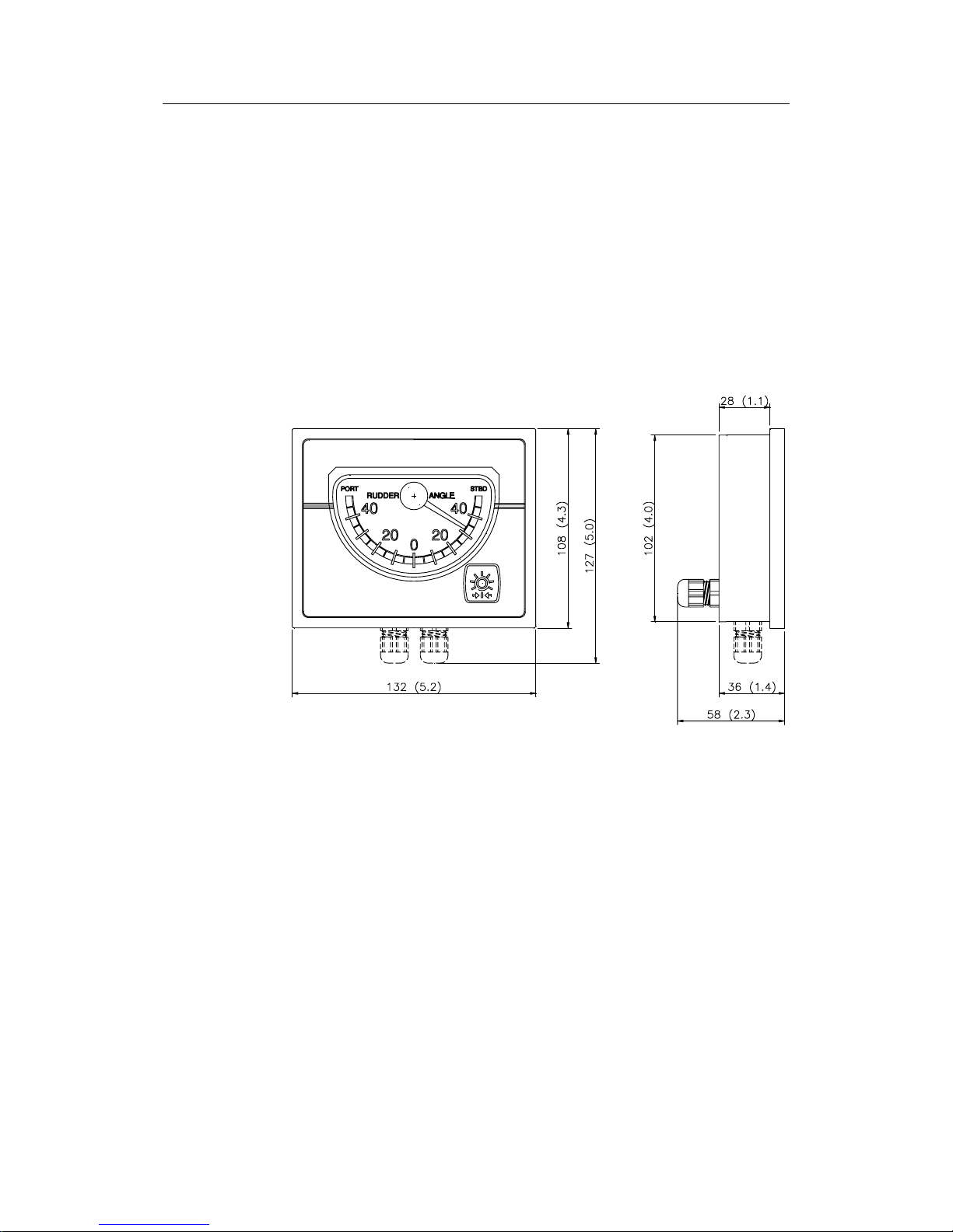
2. TECHNICAL SPECIFICATIONS
Dimensions:................................................................................................. See Figure 2-1
Weight: ......................................................................................................................1.0 kg
Material: .......................................................................................Epoxy coated aluminum
Supply voltage:......................................... 12/24V DC –10%/+30%, polarity independent
Power consumption: .............................................................................................Max 3 W
Environmental protection: ........................................................................................... IP56
Safe distance to magnetic compass: ................................................................. 0.3 m (1 ft)
Wheelmarked according to:
Council Directive 96/98/EC of 20 December 1996 on Marine Equipment
as amended by directive 2001/53/EC
Temperature range:
Operating: .............................................. –25 to +55°C (–13 to +130°F)
Storage: ................................................. –30 to +70°C (–22 to +158°F)
Page 6
Simrad RI35 Mk2 Rudder Angle Indicator
4 20220919D
Input signal: ........................................................Frequency 3400 Hz (midship reference),
±20Hz/degree, polarity independent.
Current: 0.1 - 1.1mA (midship 0,6mA), polarity independent
NMEA 0183 RSA (min. 10 Hz): $--RSA,x.x,A,x.x,A*hh<cr><lf>
Output signal: ............................. NMEA 0183 RSA 20Hz: $--RSA,xx.x,A,,*hh<cr><lf>
Accuracy:........................................................................................ ±0.5° (Indicator alone)
Cable:................................................................ 20 m, single twisted pair (not connected).
Rudder Feedback Units: ............................................ RF300, RF300S (frequency signal),
RF45X (current or frequency signal),
RF100 (current signal).
Figure 2-1 RI35 Mk2 Dimensions
3. INSTALLATION
The RI35 Mk2 is designed for flush, bulkhead or bracket mounting, and
should be positioned in a location in clear view of the helmsman. When
the mounting location is determined, the cables should be connected to
RI35 Mk2 before the unit is mounted. Cables may be taken out
underneath, or in the back of the RI35 Mk2.
Page 7

Instruction manual
20220919D 5
3.1 Connections
Stand alone rudder angle indicator(s)
RF45X Rudder Feedback Unit (Current signal)
FREQ SUPPLY
CURR
RF45X
RUDDER FEEDBACK
UNIT
RI35 Mk2
RUDDER ANGLE
INDICATOR
SUPPLY VOLTAGE 12/24VDC
RI35 Mk2
RUDDER ANGLE
INDICATOR
GREEN
RED
BLUE
+
+
+
+
FREQ SUPPLYCURR
NMEA NMEA
Figure 3-1 RI35 Mk2 - RF45X Stand alone wiring diagram
Note ! If more than one indicator is needed, the other indicators must be
connected via the NMEA ports. Max. 5 indicators (1+4).
RF300 Rudder Feedback Unit
* Non polarized (colour independant)
FREQ SUPPLYCURR
RF300
RUDDER
FEEDBACK
UNIT
RI35 Mk2
RUDDER ANGLE
INDICATOR
RI35 Mk2
RUDDER ANGLE
INDICATOR
*
*
FREQ SUPPLYCURR
SUPPLY VOLTAGE: 12/24VDC
NMEANMEA
Figure 3-2 RI35 Mk2 – RF300 Stand alone wiring diagram
More indicators (max. 5) are connected in parallel.
Page 8

Simrad RI35 Mk2 Rudder Angle Indicator
6 20220919D
Connection to J3XX and J50 Junction units
Figure 3-3 and Figure 3-4 is only valid for J50 Junction Unit and for
J3XX Junction Units that have Main PCB rev. E onwards. For older
J3XX versions see page 8.
The interconnection cables are screened, and the screen should be
grounded in the autopilot junction unit. See Figure 3-3 through Figure
3-9 for connections to the different autopilot junction units.
Figure 3-3 RI35 Mk2 – J50/J3XX, Wiring diagram
dependent of autopilot function
Page 9

Instruction manual
20220919D 7
Figure 3-4 RI35 Mk2-J50/J3XX, independent function of
autopilot
This connection gives you a full functioning indicator also with the
autopilot switched off.
Page 10

Simrad RI35 Mk2 Rudder Angle Indicator
8 20220919D
Connection to older revision J3XX Junction
units
Figure 3-5 and Figure 3-6 is only valid for J3XX Junction units that
contains Main PCB revision D or older (A, B, C).
The interconnection cables are screened, and the screen should be
grounded in the autopilot junction unit.
Note ! If the J3XX junction unit has 24V supply (Vbat), the RI35 Mk2 Limiter
(part no. 22084990) must be connected to RF+ as shown in Figure
3-5.
*
* Non polarized (colour independant)
JUNCTION UNIT
MAIN PCB
Rudder
Feedb.
RF +
RF
FREQ SUPPLYCURR
RF300
RUDDER FEEDBACK
UNIT
RI35 Mk2
RUDDER ANGLE
INDICATOR
RI35 Mk2
RUDDER ANGLE
INDICATOR
*
*
*
FREQ SUPPLYCURR
*
Vbat+
DATABOX
(NMEA Input 1)
NMEA NMEA
GND
Figure 3-5 RI35 Mk2 - J3XX (old) Wiring diagram
Note!
*
Note!
24V only
Rudder
Feedb.
RF +
RF
*
Page 11

Instruction manual
20220919D 9
Figure 3-6 RI35 Mk2-J3XX (old), independent function of autopilot
Note ! In order to use the indicator when the autopilot is switched off, the
RI35 Mk2 Limiter must be connected as shown.
Connection to J45A/J45S Junction units
Note ! When the RF45X Rudder Feedback Unit is connected to J45A or J45S
junction units, the S1 plug-in strap on the RF45X PCB must be set to
position “AP45”.
* Non polarized (colour independant)
J45A JUNCTION UNIT
RF45X
RUDDER FEEDBACK
UNIT
12 11 10
GND
RUDDER FB I/P
+OUT
BLUE
GREEN
RED
*
FREQ SUPPLYCURR
RI35 Mk2
RUDDER ANGLE
INDICATOR
SUPPLY VOLT AGE 12/24V
RI35 Mk2
RUDDER ANGLE
INDICATOR
FREQ SUPPLY
CURR
*
NMEANMEA
Figure 3-7 RI35 Mk2 - J45A Wiring diagram
Note ! Autopilot supply and Indicator supply must have common GND.
Page 12

Simrad RI35 Mk2 Rudder Angle Indicator
10 20220919D
* Non polarized (colour independant)
J45S JUNCTION UNIT
RF45X
RUDDER FEEDBACK
UNIT
12 11 10
GND
RUDDER FB I/P
+OUT
BLUE
GREEN
RED
*
FREQ SUPPLYCURR
RI35 Mk2
RUDDER ANGLE
INDICATOR
SUPPLY VOLTAGE 12/24V
RI35 Mk2
RUDDER ANGLE
INDICATOR
FREQ SUPPLY
CURR
*
Use a separate
terminal fo r this
connection
NMEA NMEA
Figure 3-8 RI35 Mk2 - J45S Wiring diagram
Note ! Autopilot supply and Indicator supply must have common GND.
Connection to J101A/J200S Junction Units
J101A/J200S JUNCTION UNIT
RF100
RUDDER FEEDBACK UNIT
RI35 Mk2
RUDDER ANGLE
INDICATOR
SUPPLY VOLTAGE 12-24V DC
*
12 11 10
GND
RUDDER FB I/P
+OUT
BLUE
GREEN
RED
11
FREQ SUPPLYCURR
GREEN
* Non polarized (colour independant)
Use a separate terminal
for this connection
NMEA
RI35 Mk2
RUDDER ANGLE
INDICATOR
*
FREQ SUPPLYCURRNMEA
11
Move this connection to
the next instrument if two
are installed
Figure 3-9 RI35 Mk2 - J101A/J200S Wiring diagram
If more than two indicators are needed, use the NMEA port as per
Figure 3-10.
Note ! Autopilot supply and Indicator supply must have common GND.
Page 13

Instruction manual
20220919D 11
3.2 Use of NMEA
The NMEA port on the RI35 Mk2 is unidirectional, i.e. it is
automatically configured for input (listening) or output (talking). The
listener port is also non-polarized.
For best performance, if the RI35 Mk2 is to be used with a nonSimrad rudder feedback outputting NMEA data (RSA), 20Hz is
recommended. Max. 5 indicators (1+4).
FREQ SUPPLY
CURR
RF45X
RUDDER FEEDBACK
UNIT
RI35 Mk2
RUDDER ANGLE
INDICATOR
SUPPLY VOLTAGE 12/24VDC
RI35 Mk2
RUDDER ANGLE
INDICATOR
GREEN
RED
BLUE
+
+
+
FREQ SUPPLY
CURR
NMEA NMEA
RI35 Mk2
RUDDER ANGLE
INDICATOR
FREQ SUPPLY
CURR
NMEA
+
Figure 3-10 RI35 Mk2 – NMEA connection
3.3 Panel mounting
• Make a panel cut-out of 126 x 102
mm.
• Use the supplied fastening device to
secure the unit to the panel. See Figure
3-11.
Figure 3-11 RI35 Mk2 Panel mounting
Page 14

Simrad RI35 Mk2 Rudder Angle Indicator
12 20220919D
3.4 Bracket mounting
• Mount two of the bracket halves to the RI35 Mk2.
• Temporarily bolt together the other two halves of the bracket to the
first two halves.
• Hold the RI35 Mk2 in place by hand and mark the 4 holes for the
fixing screws on the mounting surface.
• Remove the RI35 Mk2, drill the 4 mounting holes in the mounting
surface.
• Unbolt the temporarily fitted bracket halves and secure them to the
mounting surface using the self-tapping screws.
• Assemble the complete bracket again and adjust the RI35 Mk2 to
best viewing angle and tighten up the mounting bracket bolts.
Figure 3-12 RI35 Mk2 Bracket mounting
3.5 Illumination
Internal LED’s illuminates the scale. The illumination is turned on and
adjusted in three steps by the front panel keypad.
Page 15

Instruction manual
20220919D 13
3.6 Zero adjust
Note ! Prior to making a zero adjustment on the indicator, make sure the
feedback unit is installed and aligned according to it’s mounting
instruction.
Autopilots with no rudder zero adjust
With the rudder amidships, the indicator should read zero. If not,
adjust the pointer to zero reading by pressing and holding the
illumination key for 5 (five) seconds. The pointer will now adjust
itself to zero confirmed by a 1-second beep.
Autopilots with rudder zero adjust
Follow the instructions on the autopilot manual to zero adjust the
rudder feedback.
Note ! There may be a difference in the RI35 Mk2 and the autopilot reading.
This is normal because the autopilot zero adjust compensates for drag
caused by the hull, flaps etc. If you prefer the readings to be aligned,
then put the rudder amidships using the RI35 Mk2 as reference, and
then zero adjust the autopilot.
Autopilots with “Rudder feedback calibration”
If the RI35 Mk2 has a different deflection compared to the readout on
the autopilot (i.e. hard over stbd. shows 40° on the autopilot, but only
30° on RI35 Mk2) it is most probably caused by the “Feedback
calibration” adjustment made in the autopilot.
To make them read the same; Make a new “Feedback calibration” and
set the port and stbd h.o. angle to the same angle as RI35 Mk2 is
showing.
Note ! The RI35 Mk2 has been designed to be a “true” reading instrument,
and therefore has no deflection adjustment.
3.7 Reversed deflection
On installations where the rudder feedback unit is mounted upside
down, the deflection of the pointer will be reversed. To make it
correct, move the rudder to approximately 10° either way then press
and hold the illumination key for 10 (ten) seconds. The pointer will
then first travel to zero then continues to the opposite side of the scale
confirmed by a 2-second beep.
Page 16

Simrad RI35 Mk2 Rudder Angle Indicator
14 20220919D
Note ! If you let go of key before conformation of reversed deflection has
been given, the RI35 Mk2 will think you meant to do a zero adjust and
leave the pointer at zero. Then simply repeat section 3.6.
4. MAINTENANCE
Simrad rudder angle indicator equipment will need no special
maintenance. It is, however, essential that the mechanical linkage
Rudder stock - Rudder Feedback Unit is regularly checked and
maintained in good condition to avoid misalignment.
5. TEST MODE
In the incident of an error, the RI35 Mk2 has a built in self-test mode
for easier trouble finding. Holding down the illumination key during
power-up accesses the automatic self-test. A short beep after the long
start-up beep indicates that you have entered self-test mode
successfully.
The self-test will now run the pointer to 45 deg port and 45 deg
starboard, then 20 deg port, 20 deg starboard.
In 1-second intervals the self-test will set all 3-illumination levels.
When self-test is finished the RI35 Mk2 will run pointer to 0 deg and
stay there until power is recycled.
During self-test operation the NMEA port first transmits the message
(PRTNV), and then after 200 mS the message (PRTNR) as per below.
Each of the messages will be sent every 400 mS.
Note ! With no signal input the pointer moves out of scale to port (after 5
seconds).
$PRTNV,RI35MK2,HW:x,SW:x.xx,Date:xxxx/xx/xx*hh<cr><lf>
Hardware release
Software release
year/month/day
Selftest count
EEPROM error
$PRTNR,xxx,xxx,x*hh<cr><lf>
1: EEPROM contains default
0: EEPROM not in default
Page 17

Instruction manual
20220919D 15
6. SPARE PARTS
Art. no. Description
22084024 RI35 Mk2 Rudder Angle Indicator
22082929 Installation accessories
22083265 RI35 Cable
22083943 RI35 Mk2 Board assy (PCB)
22083968 RI35 Mk2 Front Panel
22084016 RI35 Mk2 Front Housing
22083992 RI35 Mk2 Back Cover
44164135 Blind plug
44140796 Cable gland
44141174 Seal (o-ring)
44140812 Screw, 3x7 mm
44148898 Screw, M4x12
22083307 Spacer
44163699 Plug-in terminal, 2 pole
44119154 Diode LED Green HLMP 1540
44138725 Dimmer Switch B3F
22084990 RI35 Mk2 Limiter (for 24VDC and separate supply
with old J3XX junction unit)
Page 18

Simrad RI35 Mk2 Rudder Angle Indicator
16 20220919D
 Loading...