

Page 1
Instruction manual
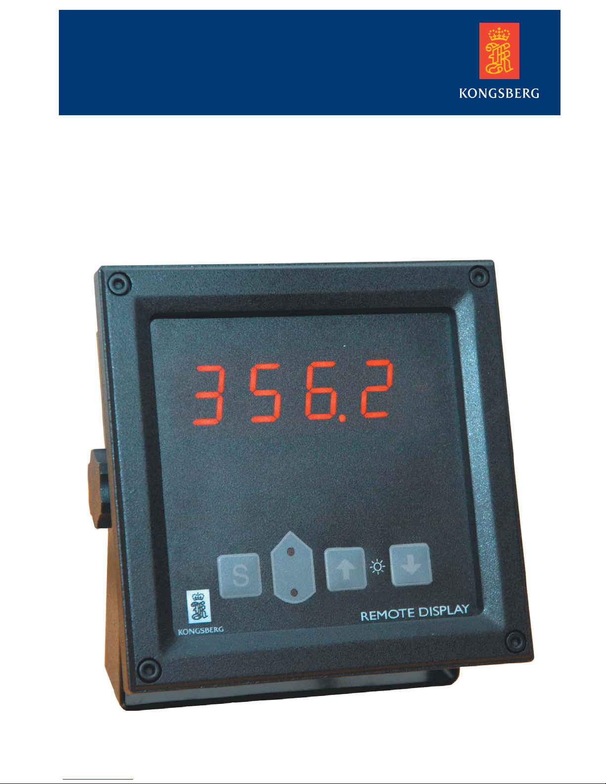
Remote display RD301
Digital depth repeater
RD301 User manual
Page 2

RD301 User manual
INTRODUCTION
The RD301 remote display is made for use with the EA400/
EA600 and the EN 250 navigation echo sounder. It may also be
used with other echo sounders, if they have NMEA0183 output.
The RD301 is a depth repeater with alarm setting. The operator
may select alarm depth in the meny.
Maximum depth readings are 9999 m and a resolution of 0.1 m.
Brightness is adjusted on the front panel. Brightness can,
optionally, also be adjusted from a remote controller.
OPERATION
1. To switch the unit on: Press any key.
To switch the unit off: At the same time, press both the Up
and the Down key.
2. To adjust brigthness: Press the Up/Down keys to find suitable
setting.
3. To select depth alarm: Press the S key once and enter alarm setting
mode. The display shows “SetA“. Set the wanted depth by
using the Up and Down keys. When wanted alarm depth is
set, the unit will go back to normal mode operation after 15
seconds, or press S to the depth occur. When depth below
transducer become the same, or less, than the alarm depth,
the display will indicate “AL“ alternating with actual depth.
To set alarm off: Repeat operation number 3. and set alarm
depth to 0 m.
4. To select readings in feet, meters or fathoms: Press the S key
twice and enter alarm setting mode. The display shows “SetU “.
Select requested reading by pressing the Up or Down key. When
readings is set, the unit will go back to normal mode operation
after 15 sec, or press S to the depth occur.
5. To select transducer position (Only for EN 250): Press the S
key three times and enter the transducer selection mode. The display shows “SetP”. Press the Up/Down keys to select between
the four choices: Unknown, Forward, Backward or Auto.
- The Unknown selection decode any NMEA depth message and
shows the depth on the display. The position leds will then be
off.
- The other selections decode the NMEA message $PSKPDPT.
If Forward is selected, only the readings from the forward
transducer is shown, and if Backward is selected, only the
readings from the backward transducer is shown.
- The Auto selection switches between Forward, Backward
and Unknown depending on the NMEA messages available.
The led for positions will shift automatically and blink every
third second, indicating that the Auto selection is active. If
the transducer position is unknown, both leds will be on and
blinking.
1 857-164821aa
Page 3
NMEA Input
1. Accepted messages (NMEA0183,version 2.30),
talker identifier is not processed:
$PSKPDPT,x.x,x.x,x.x,xx,xx,c-c*hh<CR><LF>
Echo sounder channel number (0-99)
Maximum range scale in use, meters
Water depth relative to transducer, meters
* Text string, indicating transducer position: FWD/AFT/PORT/STB.
If position is not preset by operator, empty field is provided.
(Cd7019)
Transducer location *
Bottom echo strength (0,9)
Offset from transducer, meters
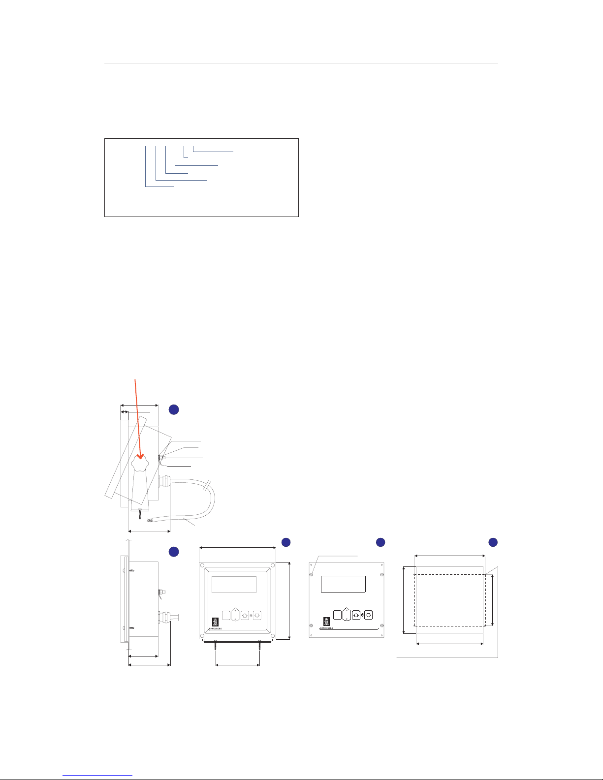
PANEL MOUNTING
A Make a cut out in the Panel (5): 125 x 125 mm.
B Remove the mounting bracket (1).
C Unscrew the 4 screws in the frame (3) (one in each corner)
and remove the frame.
D Put the Monitor (4) in the cut out and mark the 4 center-
points for the drill in the Panel (1)(2). (The drilling holes
diam. depends on thickness and material in the Panel).
E Use appropriate bolts with diameter 2.9 mm. Length
Mounting bracket
62(2.441)
13(0.492)
1
depends on the Panel thickness.
F Finally put on the frame (3). Make sure that the screw
heads correspond with the cut outs in the frame.
RD301 User manual
- Depth &Draught
SDDPT,xxxx.x,xxxx.x,xxxx.x <Cr><Lf>
(used by EA400 and EA600)
- Depth below transducer
SDDBT ,xxxx.x,f,xxxx.x,M,xxx.x,F)
- Depth below transducer by EN 250
proprietary sentence shown to the left
(only for EN 250)
Washer DIN 6797 (2x)
Nut M4
Ground stud 4M x 12
Tab size 6.3 x 0.8
(1)(2), apply sufficient amount of water sealant compound
between the monitor (4) and console (1)(2). Before the
frame (3) is remounted, apply sufficient amount of water
sealant compound in the inner area of the frame and on the
edges of the monitor (4), to ensure that water can not penetrate into the monitor (4). The front panel of the monitor
is waterproof.
Before fixing the monitor (4) in the cut out area in console
70(2.736)
50(1.968)
70(2.736)
Cable length: 1.5m. (4.9 ft.)
2
(CD7018)
144 [5,669]
S
100(3.937)
3
Hole diam. %%C4.0 (0.157)
ft
M
F
144 [5,669]
RD301
S
4
ft
M
F
125 [4,921]
RD301
The drilling holes diam. depends on thickness and material in the Console.
Some remote displays may have the text “REMOTE DISPLAY” instead of
“RD301” on the front.
857-164821aa 2
132,5 [5,217]
5
Cut out
96 [3,780]
125 [4,921]
Page 4
RD301 User manual
Remote unit (DCE) to
be connected as described
in applicable documentation
5
Looking into
female 9-pin
D-pin connector
Looking into
male 9-pin
D-pin connector
W103 / Rev G
1
9
6
1
5
96
Screen
View
Standard RS-232 serial line
Environmental conditions according to
IEC60945
Supply voltage: 24 Vdc (20-32 V)
Power consumption: 3 W at 24 V
Display area, size: 20 x 11 mm
Operating temperature:
-15 to +55 degree C, according to IEC60945. To increase service
ability and life-time, we suggest the working temperature to be
held at 0 to +40 degrees C.
Storage temperature: -20 to +70 degree C
Humidity: 10 - 90% relative, no condensation
Protection: IP 56
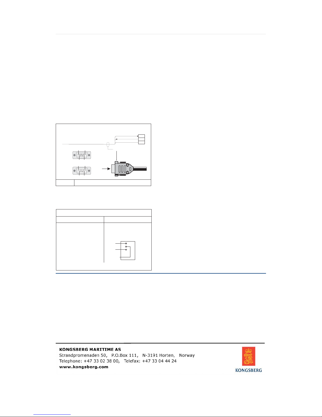
Generic RS-232 Serial line
Local (DTE) 9-pin
Ground
Toplug housing
‘D’ connector
Rx
Tx
This cable comprises a multi-purpose serial
line. It provides interface with any peripheral
2
unit. One end of the cable connects to the local
3
5
unit (DTE) with a 9-pin ‘D’ connector, while
the other connects to the peripheral (DCE) as
described in the peripheral unit’s documentation.
Note that this cable does not support all the signals in the standard RS-232 specification.
WIRING CONNECTING
COLOUR
RED
BLACK
BLUE
WHITE
ORANGE
GROUND WITH GROUND STUD
SIGNAL
+ 24V
- 24V
NMEA IN+
NMEA IN/OUT-
NMEA OUT+
About this manual
Kongsberg Simrad AS makes
every effort to ensure that the
information contained within
this document is correct.
However, our equipment is
continuously being improved
and updated, so we cannot
assume liability for any errors
which may occur.
Note about wiring
A wrong type of cable has been used in the production of the first
series of RD301 repeaters. This applies to repeaters with serial
no. 030031 through 030050.
COLOUR
GREEN
YELLOW
GREY
DIM+
DIM-
DIMKEY
SIGNAL
DIMKEY
REMOTE
DIMMER
Two of the wires in the cable have a different
DIM+
colour coding from the original:
DIM-
- NMEA IN/OUT Brown wire
(originally white)
- DIMKEY Violet wire
(originally grey)
Other cables as marked on the rear wall of the
repeater.
Warning
The equipment to which this
manual applies must only be
used for the purpose for which
it was designed. Improper use
or maintenance may cause
damage to the equipment or
injury to personnel. The user
must be familiar with the
contents of the appropriate
manuals before attempting to
install, operate or maintain the
equipment.
Kongsberg Simrad AS disclaims any responsibility for
damage or injury caused by
improper installation, use or
maintenance of the equipment.
Service
All service requests should
be made to the local Kongsberg Simrad representative.
Adjustments and repairs
should only be performed by
qualified service engineers,
and unqualified repair attempts
will void the warranty.
Copyright
© 2003 Kongsberg Simrad AS
The information contained
within this document remains
the sole property of Kongsberg Simrad AS. No part of
this document may be copied
or reproduced in any form or
by any means, and the information contained within is
not to be communicated to a
third party, without the prior
written consent of Kongsberg
Simrad AS.
3 857-164821aa
 Loading...