

Page 1

SIMRAD
MARINE
RADAR
RA771UA
INSTRUCTION
MANUAL
PIN
855-106335
Page 2

INSTRUCTION
MANUAL
FOR
MAFUNE
RADAR
TYPE
RA771
UA
ANRITSU
CORPORATION
MAY.
‘92
Page 3
WARNING
HIGH VOLTAGE
High voltage ranging from 300V to
lOkV
are used
in
this
equipment.
Do
not touch
the
inside of the equipment during
inspection, repair,
or
maintenance until you
are
certain that
the
power switch
on
the
display unit and main power switchboard
are
turned off. Even
after
these
switches are turned off, there
may
be
high
static
voltage
at
condensers,
etc.
Always ground
high
-
voltage points using an insulated conductor.
DURING MAINTENANCE
OF
THE SCANNER UNIT
THE ANTENNA MUST NOT BE ROTATED
Never
start
maintenance work on the scanner unit until
you are sure that the main
power
switch
on the switchboard and
the power switch on the display unit
are
turned off, and the
antenna motor
-
line
in
the scanner unit
is
disconnected
of
from
connector
52
on the.MOD
PC
board. Accidental rotation of the
antenna
is
a potential hazard
to
personnel.
A
suitable,
conspicuous sign such as
"
MAINTENANCE
IN
PROGRESS
"
should be
posted on
the
display unit during maintenance
work.
Page 4
CONTENTS
1.
2.
3.
4.
5.
GENERAL
1.1
Introduction
1.2 Features
OPERATION
2.1 Key Layout
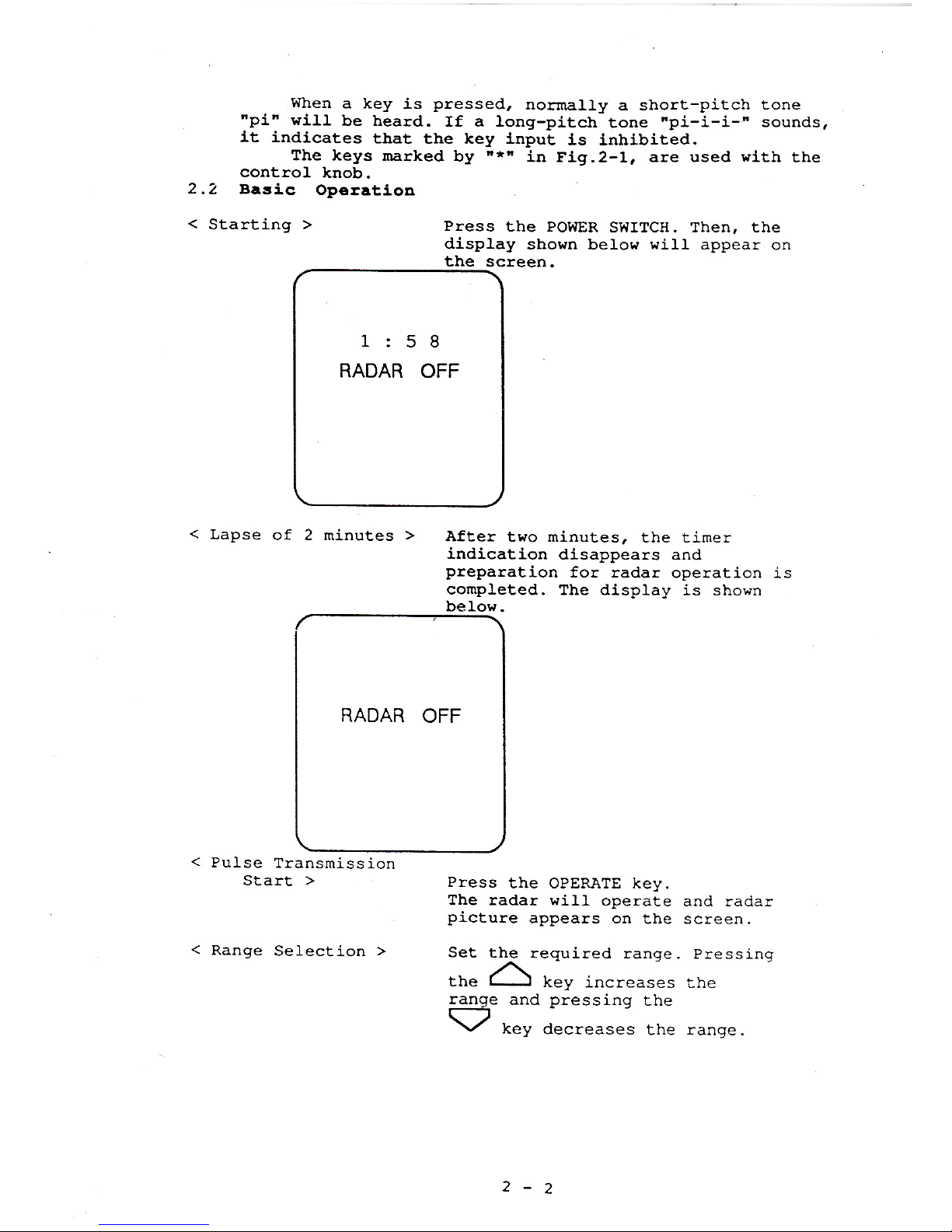
2.2
Basic
Operation
2.3 Sea
Clutter
Suppression (STC)
2.3.1 Manual Sea
Clutter
Suppression
2.3.2 Automatic Sea Clutter Suppression
2.4 Rain and Snow Clutter Suppression
(FTC)
2.5 Measuring
Target
Bearings
(EBL)
2.6 Measuring Target Rages
2.6.1 Rough
Range
Estimation (Range Rings)
2.6.2
To
Measure Accurate
Ranges
(VRM)
Observation
2.7 Stretching Echoes
from
Target
for
Easy
Target
2.8 Plotting locus of Echoes
from
Moving
Targets
2.9 Setting Guard Zone around
Your
Ship
2.10 Off
-
Centering
2.11
Rejecting Interference
from
Other Radars
2.11.1
What
is
Radar
Interference?
2.11.2 Rejecting
Radar
Interference
(IR)
2.12 Erasing Heading Marker
2.13 Switching the Display Modes
2.14 The second
EBL
and
VRM
2.15 The floating function of
the
second EBL and
VRM
2.16 Setup Modes
2.16.1 Entering Setup Mode
2.16.2 Return
to
the
Radar
Mode
2.16.3 Description
of
Each Setup Mode
2.17 Navigation Data Display
2.18 Caution
INTERPRETING
RADAR
PICTURES
3.1 Propagation Characteristics of Radar Radio Waves
3.2 Echo Strength and Incident
Angle
of
Target
3.3 Shadow Zones
3.4
False
Echoes
MAINTENANCE
4.1
Preventive maintenance
4.2 Checking Fuses and Voltages
INSTALLATION AND ADJUSTMENT
5.1
5.2
5.3
5.4
5.5
5.6
8.7
5.8
Unpacking Instructions
Installation Materials
Power Requirements
5.3.1 Power Supply Voltages
5.3.2 Power Systems
Proper Location for Installation of Radar
5.4.1 Scanner Unit
Installing Scanner
Unit
Installing Display
Unit
5.6.1 Cable Connection
5.6.2 Display unit grounding
5.6.3 Adjustments
Laying Cables
Installing the External Buzzer
Page 5
5.9 Interface
5.9.1
Compass
Interface
5.9.2
NMEA
Interface
Interference
(EMI)
5.10.1
On
Radar
Installation
5.10.2
Radio
Equipment and Using Frequency
5.10.3 Improvement Procedure
for
EMI
5.10 Countermeasurement
for
Electromagnetic
6.
SPECIFICATIONS
6.1 Principal Specification
6.1.1
Overall
Characteristics
6.1.2
Scanner Unit
6.1.3
Display
Unit
6.1.4 Interface Signals
6.1.5
Allowable
Safe Distance
from
Magnetic
Compass
6.2
Standard Equipment
6.3 Option
6.4
Dip
switch selection
ATTACHED DRAWINGS
~~
General System Diagram
Scanner Unit External
View
Display Unit External
View
Outline Drawing Rectifier Unit
Rectifier
Unit External
View
Inter
Connection Diagram
Scanner Unit Circuit
Diagram
Display Unit Circuit
Diagram
Rectifier Unit Circuit Diagram
Rectifier
Unit Circuit Diagram
24W138742
23W61747
~ ~~
23W61200
23W56729
24W138743
24W138587
23W61043
24W130456
24W138330
Page 6
1.
GENERAL
1.1
Introduction
The
RA771UA
Marine Radar
is
a
marine navigational
pulse radar with
4kW
peak power output for
small
and
medium
-
sized vessels. The Display Unit uses
a
10-inch
CRT
to display monochrome picture images
at
four different
brightness levels.
recently developed by Anritsu Corporation.
It
is
one of a series of digital marine-radars
1.2
Features
Many versatile advanced technologies, such
as
a
microcomputer, an LSI exclusively designed for video
signal processing, high
-
integrated
LSIs,
have been
incorporated
in
the radar circuitry.
intensities of signals reflected from targets can be
displayed
at
four different brightness levels.
In addition, various automatic functions, video image
expansion, off
-
centering, plotting, electronic cursor, and
offset
are
provided.
a.
High Resolution and Sharp Picture
ranges. This unique outstanding feature has been achieved
by using a
"
clean picture
"
circuit, that
is
a
high
resolution circuit developed by Anritsu.
b. Automatic Sea Clutter Suppression and Auto Gain
Control
(AUTO)
In addition to having conventional sea clutter
suppression, this radar has a newly
-
developed automatic
sea clutter suppressor.
has an automatic gain control
for
easy operation.
As
a result, radar video images can be stored and the
Picture resolution
is
excellent
at
short and medium
And not only a sea
clutter
suppressor, this new radar
c.
Automatic Tuning
eliminates
the possibility of miss
-
tuning
or
function
lowering of gain.
d. Off
-
Centering
centered from the screen center. The off
-
centered position
can
be
set
to either position of
60%
forward or
60%
backward.
size.
e.
Electronic Cursors
:
Markers
(VRMs)
(i)
This radar can display two
EBLs
and two
VRMs.
The
VRM
range can be displayed by nautical
miles
(NM),
kilometers
(KM)
or statute
miles
(SM)
.
(ii)
The center
of
EBL2
and
VRMZ
can be relocated
from
the
picture center (own ship point) to any point on the
picture. This offset facility for
EBL2
and
VRM2
results in
To maintain optimum gain
at
all
times,
auto-tuning
Your ship's position
in
the picture can be off-
This results
in
the
effective use of the display
Electronic Bearing Lines
(EBLs)
and Variable Range
Page 7
easy measurement
of
the bearing and range
of
any
two
selected
points.
f.
Guard Zone
EBL1.
The sector angle varies
in
about
6
degree
increments.
An
external buzzer can be easily installed
in
addition
to
built-in
alarm
buzzer.
g.
Plotting picture
screen.
The tracking
time
can
be selected
from
:
15
sec.,
30
sec.,
1
min.,
3
min.,
6
min.,
and continuous.
An
alarm
zone sector can be
set
by using
VRMl
and
The track
of
target picture can be displayed on the
2.
OPERATION
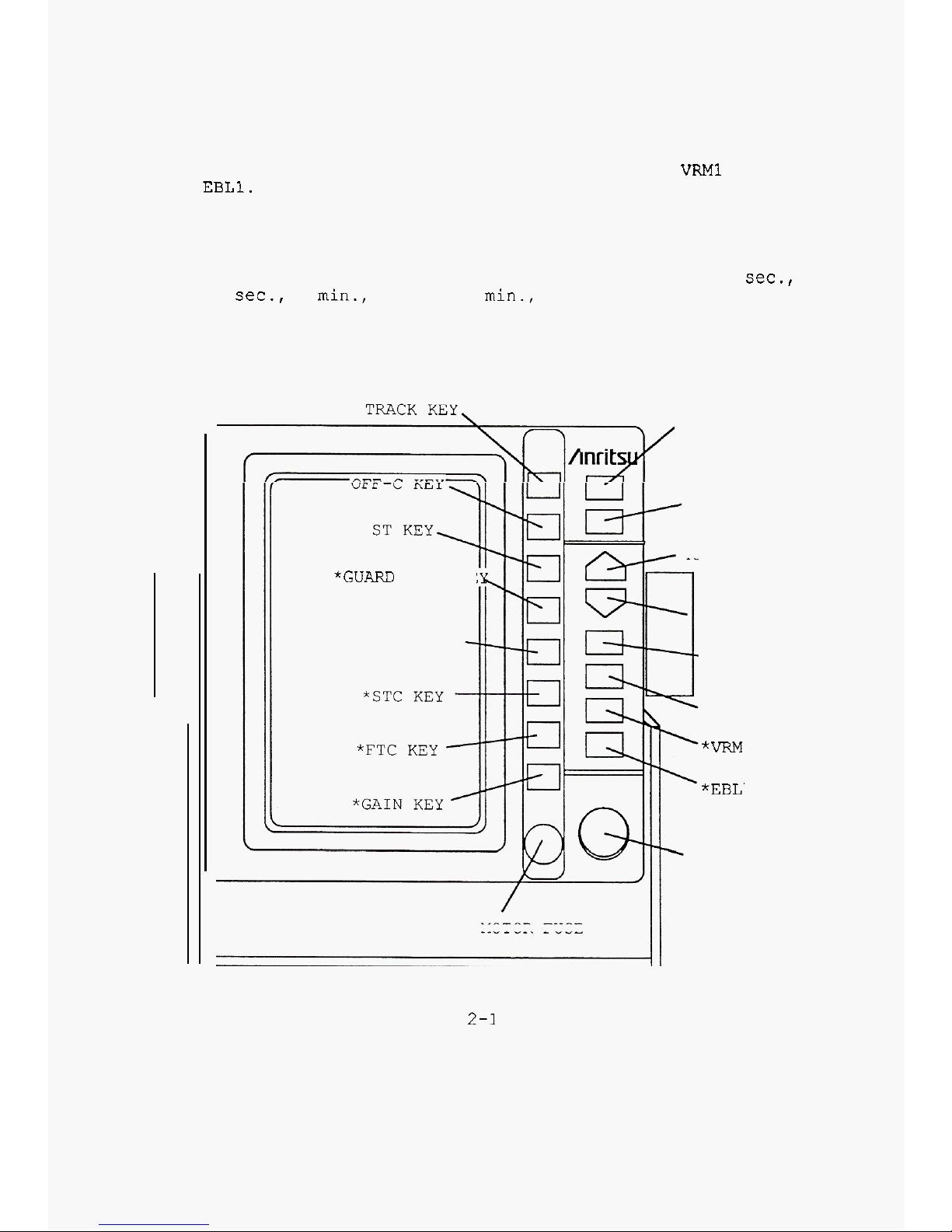
2.1
Key
Layout
The key and control knob layout
is
shown below.
POWER SWITCH
OPERATE KEY
RANGE
UP
KEY
*GUARD ZONE KE
RANGE
DOWN
KEY
RANGE RING
AUTO
KEY
BRILLIANCE KEY
*VRM
KEY
*EBL' KEY
CONTROL KNOB
MOTOR
FUSE
Fig.
2-1
Page 8
Page 9
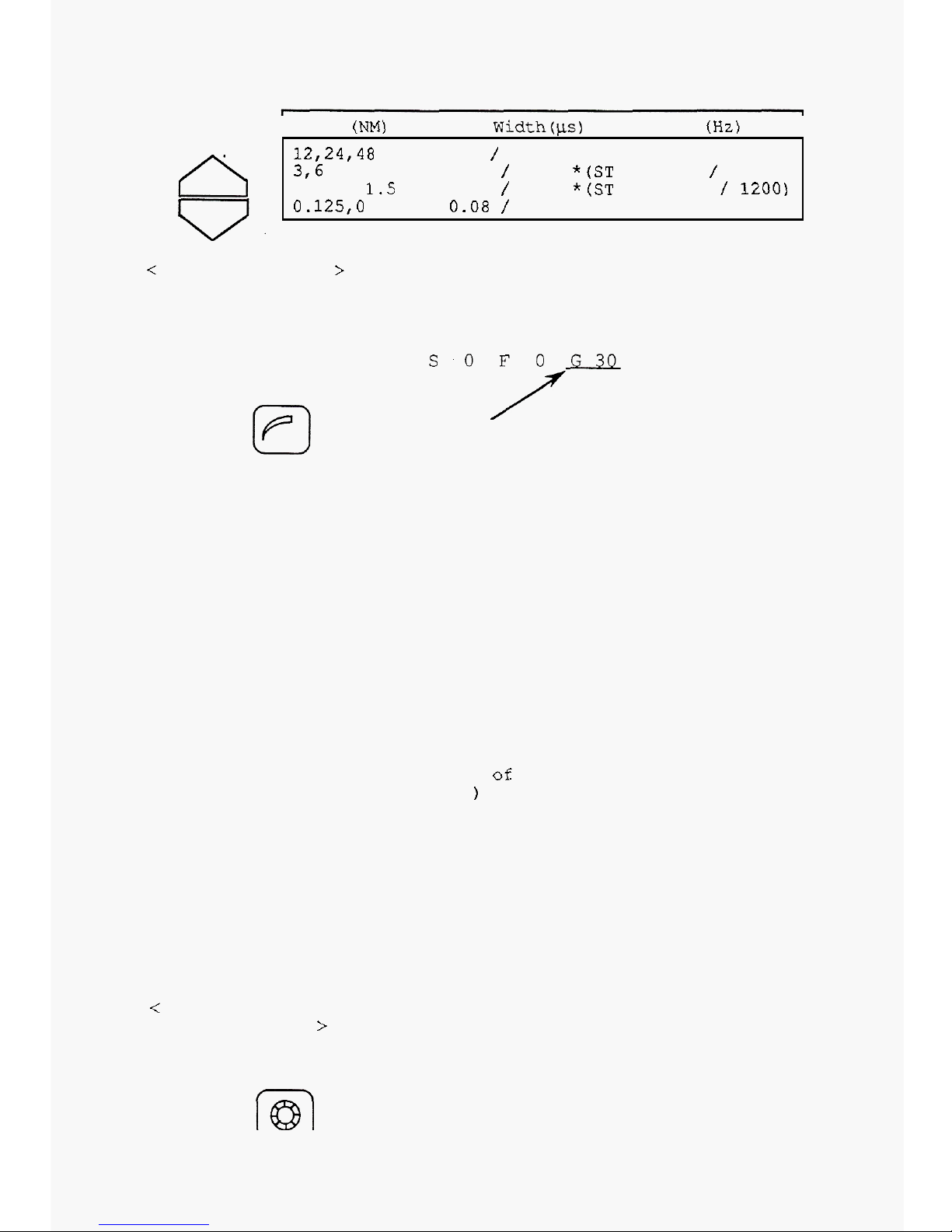
Range
(NM)
Pulse Width(+s) /Repetition
(Hz)
I
fi
12,24,48
0.8
/
600
0.5
to
1.5
0.125,O
.25
0.08 / 1800
0.25
/
1200
*(ST
ON:
0.8
/
600)
0.08
/
1800
*(ST
ON:
0.25
/
1200)
3,6
<
Gain Adjustment
>
Press the GAIN key to set the
gain adjustment mode. The underline
shown below will be displayed
on
the
screen.
Indicates that the gain
adjustment mode is selected.
Turn the control knob to adjust the
gain. The gain adjustable range is
from
0
to
50.
Turning the control knob clockwise
elevates the level, enhances
reception sensitivity and makes
targets visible. Turning the
control further clockwise changes
the brightness level of echo
signals reflected from targets with
high reflection coefficients.
For
long-range observations, increase
the gain by turning the control knob
clockwise
so
that slight receiver
noise can be observed. (Receiver
noise usually appears on the entire
surface
of
the display as speckled
noise.
)
Conversely, excessive gain at short
range
will
obscure the picture with
noise and unwanted echoes. Small
targets will be concealed in the
obscure areas.
In such a case, turn the control
knob counterclockwise to the
appropriate point. The intensities
of signals reflected from targets
are expressed as changes
of
brightness.
Adjustment
>
Press the key to change the CRT
<
Picture Brilliance
brightness and the panel
illumination. One press varies the
brilliance by one level.
U
2-3
Page 10
<
Operate Keys and
Controls
Depending
on Circumstances
>
Refer
to
paragraph
3.2
and
after.
<
To
suspend
radar
operation
>
Press
the
OPERATE
key
once.
The
radar
will
stop transmission and
the radar picture
will
disappear.
To
resume
radar operation,
press
the
OPERATE
key
once
more.
<
To
Stop
Radar
Operation
>
Press
the POWER SWITCH more than
3
seconds.
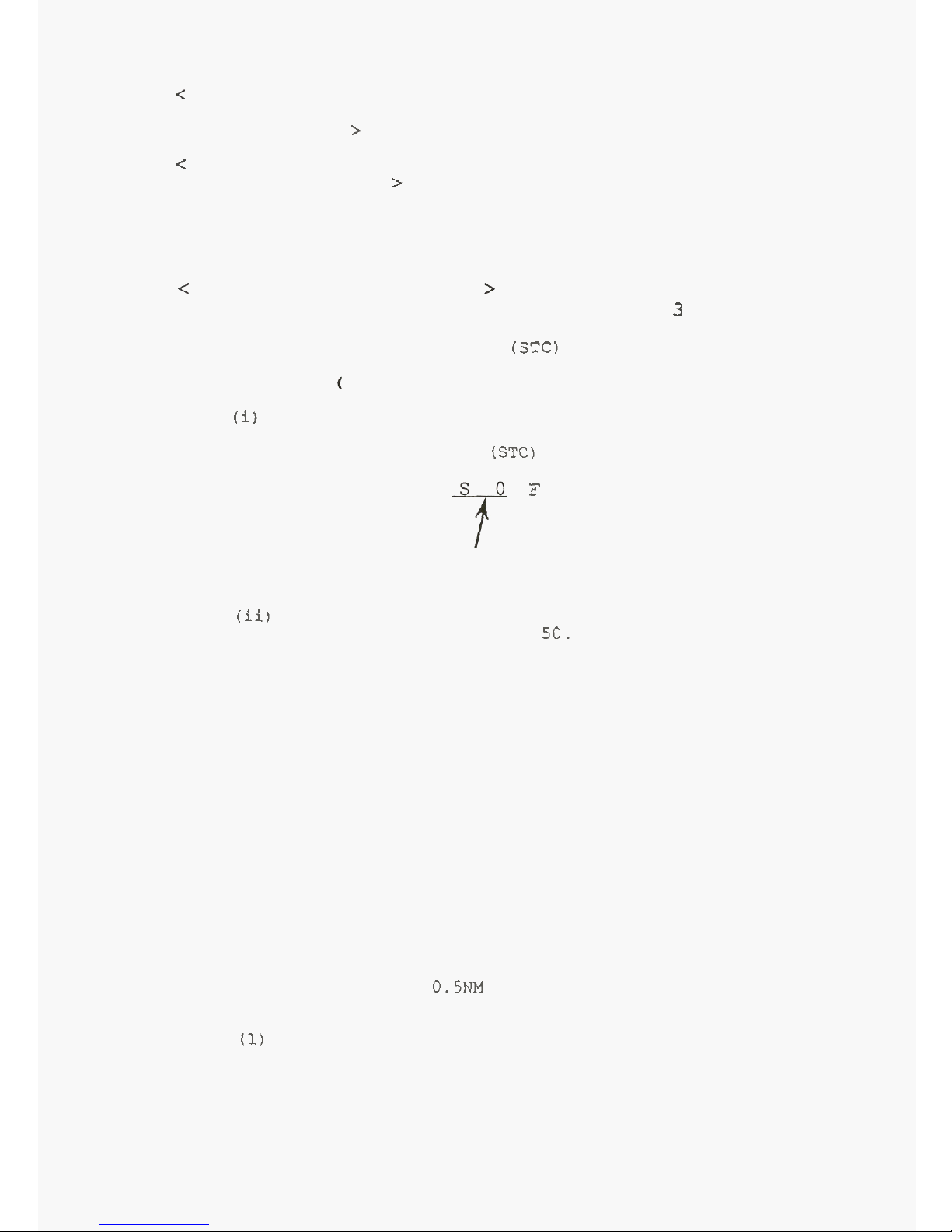
2.3
Sea
Clutter Suppression
(STC)
2.3.1 Manual Sea Clutter Suppression
(
STC:
Sensitivity
Time
Control)
(i)
Press
the STC key. The underlined numerical
indication shown below
will
be displayed and the sea
clutter suppression mode
(STC)
will
be
set.
F
0
G30
Indicates
STC
adjustment mode
is
selected.
(ii)
Turn the control knob to adjust the level. The
STC
adjustable range
is
from 0 to
50.
even when the sea
is
calm. When the sea
is
rough, intense
echoes appear over a wide area and sometimes make targets
invisible.
The STC control decreases such
sea
clutter
and makes
targets easily visible.
Turn
the control knob clockwise to
decrease sea clutter.
If
the control knob
is
turned too
far,
echo signal from important targets may disappear.
Adjust the control very cautiously by observing the
picture with utmost care.
Usually the STC control should be
set
so
that there
is
no sea clutter at
or
near the display center when the
sea
is
calm, with the distance range preset to
a
minimum
or
0.125
NM.
short-distance sensitivity (gain) lower and the long
-
distance sensitivity (gain) higher.
For
this reason, no
picture may emerge on the display
if
the sea
is
calm and
there
are
no
large targets
near
your ship when the range
is
set
to
0.125
to
0.5NM
and
the
level
is
more than
30.
2.3.2 Automatic Sea Clutter Suppression
(1)
Automatic Sea Clutter Suppression and Automatic Gain
Sea clutter
is
observed from short-range sea surfaces
The STC
circuit
is
designed primarily to make the
Control
Page 11
APPENDIX
(RA770UA
MARINE
RADAR
INSTRUCTION
MANUAL(P2-4)
)
Press the
AUTO
key. The indication shown below
will
be displayed and the auto sea-clutter suppression
mode
will
be
set.
At
the
same
time, the auto gain control mode
will
be
set.
Every pressing of the
AUTO
key, the function
and display
will
change
"
AT
1" and
"
AT
2
"
alternately.
The
GAIN
and/or the FTC
can
be
used with manual control
together with the
AUTO
mode.
Press
the STC key to return the manual control mode.
AT
1
Indicates the auto
STC
and
auto gain mode
is
selected.
The functions
of
AUTO
are
as
follows;
AT
1 : Use
this mode to watch the coast-line
in
the
channel,
or
to
watch the sea with many
small
islands
around your ship. Also use this mode in the harbor.
in the manual mode.
This mode
is
similar
to the "low
STC
and low
GAIN
"
state
AT
2
:
Use
this mode to suppress the
sea
clutter in the
open sea. This mode
is
similar to the "high STC(depends
on sea
state)
and high
GAIN
"
state in the manual mode.
note: To suppress the long
-
range rain/snow clutter, use
the manual FTC and/or
GAIN
control with
AUTO
mode.
Presetting the
ATl/AT2
level
"
AT
1
"
and
"
AT
2''
level can be
set
by using following
procedures.
1.
Set the
AUTO
mode to
"
AT
1
"
or
"
AT
2"
to change the
level.
To change the
"
AT
1
"
level,
set
the range scale more than
0.75
NM.
2.
Press
and hold the
"
BRILLIANCE
"
key
to
enter
the SETUP
MENU.
3.
Press and hold the
AUTO
key, and press the
"
RANGE-UP
"
key during the buzzer
is
sounding. The setting levels
are
displayed on the
screen
as
follows;
ATI
LEVEL(N0RM
7)
7
AT
2
LEVEL(N0RM
5)
5
4.
When change the
"
AT
l",
turn the encoder knob to change
the level. The
"
AT
1"
level changes the
AUTO-GAIN
preset
level (not
to
change the
AUTO-STC
level).
5.
When change the
"
AT
2",
press the
"
RANGE-DOWN
"
key
to
display the underline to
"
AT
2".
Then turn the encoder
knob to change the
AUTO-STC level (not to change the
AUTO
-
GAIN
level).
6.
Press
the TRANSMITT key to return the normal display.
2-5
Page 12
Press
the
AUTO
key. The indication shown
below
will
be
displayed and the auto
sea-clutter
suppression
mode
will
be
set.
At
the
same
time,
the auto gain control
mode
will
be
set.
to
"
AT
2"
and the auto sea-clutter suppression
will
enhance the effect.
Press the
AUTO
key again. The indication
will
change
AT
1
Indicates the auto STC and
auto gain mode
is
selected.
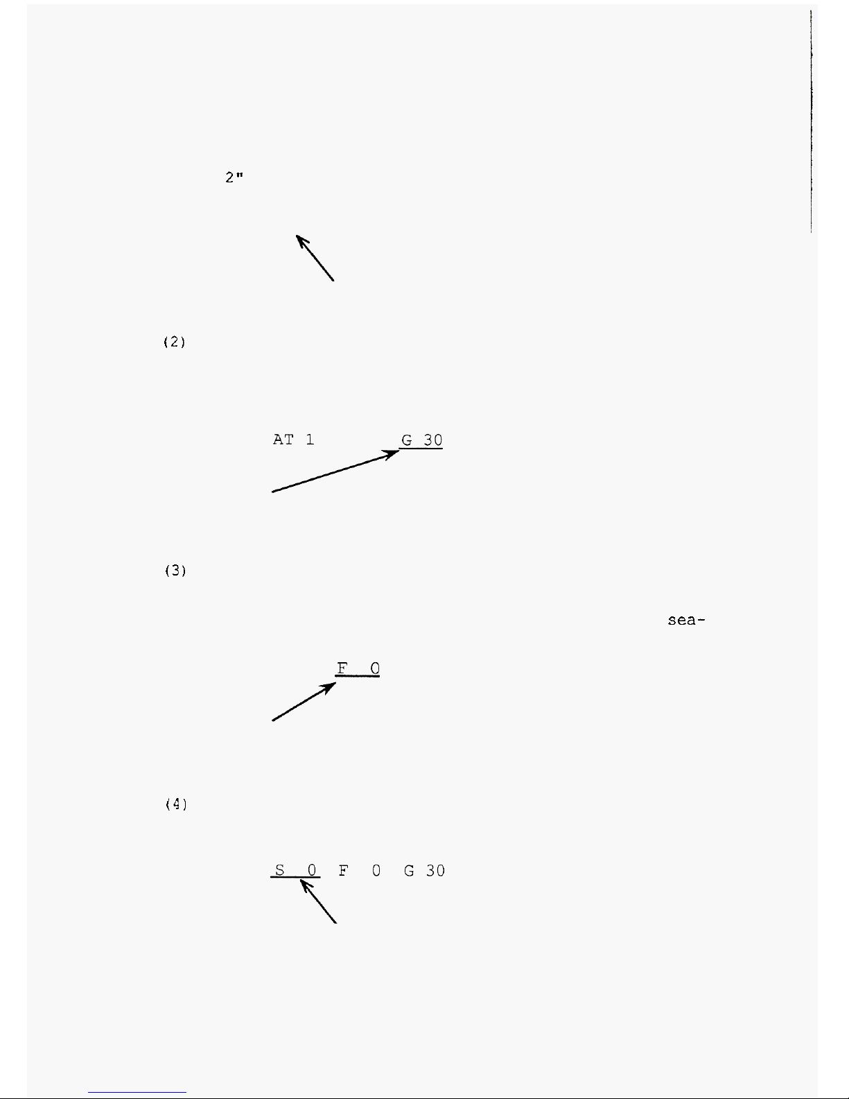
(2)
Automatic Sea Clutter Suppression and Manual Gain
Control
Press
the
GAIN
key
to
return
to
manual
gain
control
mode. The indication shown below
will
be
displayed and the
auto sea
-
clutter suppression mode
will
remain.
Indicates the auto STC and
manual gain control mode
is
selected.
(3)
Automatic Sea Clutter Suppression, Manual Gain
Control and
FTC
Control
Press
the FTC key to add the FTC control mode. The
indication shown below
will
be displayed and the auto
sea-
clutter
suppression
mode
will
remain.
AT
1
G
30
Indicates the auto STC,
manual gain
and
FTC control
mode
is
selected.
(4)
Manual control
mode. The indication shown below
will
be displayed.
Press
the STC key
to
return
to
the manual control
Indicates the STC adjustment
mode
is
selected.
2-6
Page 13
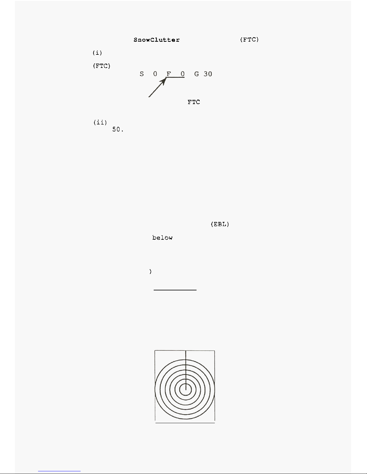
2.4
Rain
and
SnoxClutter Suppression (FTC)
(i)
Press
the FTC key. The indication shown below
will
be
displayed and the rain and snowclutter suppression
mode
(FTC)
will
be
set.
Indicates the FTC mode
is
selected.
(ii)
Turn the control knob
to
adjust the level range from
0
to
50.
Clutter from rain, snow
or
fog
may appear on a radar
In
such
a
case,
turn the control knob at the FTC mode
picture and sometimes
mask
targets completely invisible.
clockwise. Then the contours
of
concealed targets
will
appear. Since the radar uses
a
LOG
amplifier, the FTC
function
is
very effective. But
it
tends to weaken the
intensities
of
echoes from short-range targets. Adjust
STC
and gain for the best picture.
counterclockwise to level
0
when there
is
no rain
or
snow.
In this state the FTC function
is
ineffective.
Always turn the control knob at the
FTC
mode
fully
2.5
Measuring
Target
Bearings
(EBL)
Press
the
EBL
key to
select
the electronic cursor and
the indication
below
will
be displayed on the bottom of
the screen. Turn the control knob to move the
EBL
to
coincide with the target to measure the bearing from your
ship's heading.
Press
the
EBL
key once again to erase
the
EBL.
(To erase the
EBL,
the
EBL
function must be selected
at the moment.
)
EBL
0.0'
2.6
Measuring Target Ranges
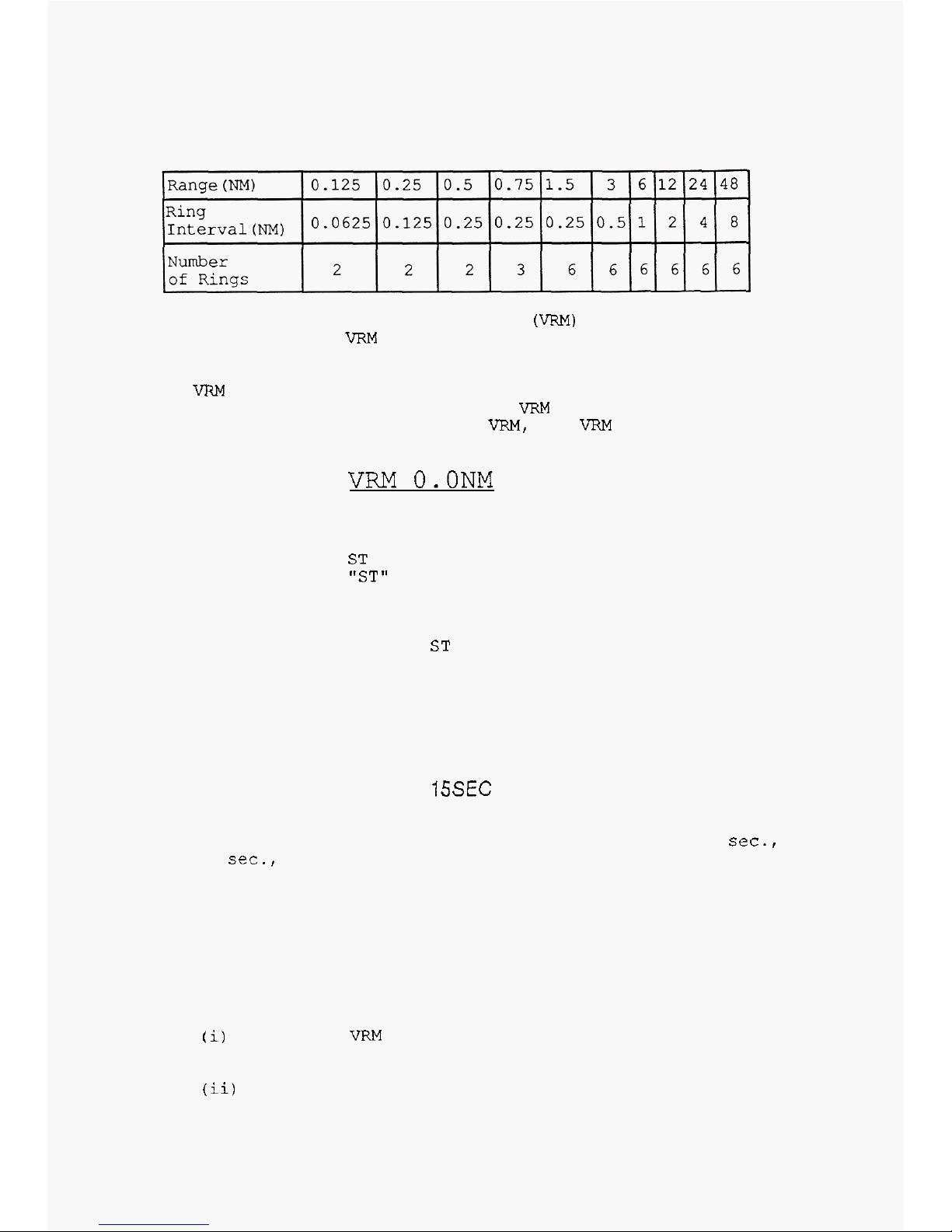
2.6.1
Rough Range Estimation (Range Rings)
Press the range ring key. Fixed range marker rings
will
be displayed
as
shown below. The interval of range
marker rings depends on the range as tabulated below:
1.5
0.25
Page 14
Press
the range ring key once
more
to
erase
the range
marker rings.
2.6.2
To
Measure Accurate
Ranges
(VRM)
ring
and the indication below
will
be displayed on the
bottom of the screen.
Turn
the control knob to move the
VRM
to
coincide with
the
target
to
measure
the
accurate
range
from your ship. Press the
VRM
key once
again
to
erase
the
VRM.
(To
erase
the
VRM,
the
VRM
function
must
be
selected
at the
moment.)
Press the
VRM
key to
select
the variable range marker
VRM
O.ONM
2.7
2.8
2.9
Stretching Echoes
from
Target
for
Easy Target
Observation
the indication "ST"
is
displayed on the upper-right
position
of
the screen.
from medium
or
longrange targets
are
too
small
for
observation.
Press
the ST key once more to
release
the
function.
Press
the ST key. The stretching function
is
set
and
This
stretching function
is
mainly used when echoes
Plotting Echo Track
from
Moving Targets
indication below
will
be displayed on the top-right of the
screen.
Press
the
TRACK
key to plot
echoes
(picture) and the
TRACK
ISSEC
The
track
of target picture
is
displayed
on
the
screen. The tracking
time
can be selected from
:
15
sec.,
30
sec.,
1
min.,
3
min.,
6
min., and continuous.
To erase
the
track of target picture, press the
TRACK
key more than 3 seconds.
Setting Guard Zone around
Your
Ship
possible collision with
other
ships, for surveillance, and
warn against running ashore.
The
guard zone function
is
used to warn against
(i)
Press
the
VRM
key and turn the control knob
to
set
the range of guard zone.
(ii)
Press the
EBL
key and turn the control knob to
set
the
EBL
direction
of
the guard zone.
L
-
8
Page 15

(iii)
Press
the
GZ
key.
The
guard zone
is
set
and
displayed
as
an
area
bounded by
solid
lines.
The
angle of
the
guard zone
is
set
in
5.625
degree increments.
To
change the guard zone
area,
press
the
GZ
key. The
area
will
change
as
45,
90,
180,
and
360
degree,
and move
to
the current
VRM
and
EBL
position.
If
a target trespasses into the guard zone, an
audible alarm sounds (pi
-
pi). The
alarm
sounds until
the
GZ
key
is
pressed.
If
a
new target trespasses into the
guard zone, the
alarm
sounds again.
To erase
the
guard zone,
press
the
GZ
key more than
3
seconds.
Notes:
1
The ward zone
is
maintained even if the range
2.10
2.11
2.12
2.13
-
key
is
used to change the distance.
external buzzer
(see
5.8).
2
If
the
powerful
alarm
is
required, install
an
Off-Centering
the screen
must
be
observed more
clearly
or
widely.
the
60%
backward
of
the
screen.
Press
the
OFF-C
key once
more.
It
will
move to
the
60%
forward of the
screen.
And
then,
another press moves the picture center to the center
of
the
screen.
This
function
is
used when the picture
in
an end of
Press
the
OFF-C
key.
The
picture center
will
move to
Rejecting Interference
from
Other
Radars
this
function, refer to "2.16 3
Setup Modes, Selecteble
Key
"
.
2.11.1
What
is
Radar Interference?
the same frequency band
is
operating
near
your ship. The
form of
the
interference pattern
is
not constant;
it
may
be
broken-line
arc
or
a broken line. Since interference
echoes vary
with
every scan period,
it
is
easy to
distinguish interference patterns from normal echoes.
2.11.2
Rejecting Radar Interference
(IR)
standard.
Erasing Beading
Marker
this
function,
refer
to
"
2.14
Setup Modes, Selectable
Key
"
.
use this function
to
erase
the
heading marker.
Selecting Display Mode
this
function, refer to "2.14 Setup Modes, Selectable
Key
"
.
This
function,is not
set
to
a
key as standard. To
use
Radar interference may occur when another radar on
The
interference
reject
function
is
equipped as
This
function
is
not
set
to a key as standard. To use
When a target
is
masked by the heading marker line,
This
function
is
not
set
to a key as standard. To use
When Gyro compass
is
connected to the radar, the
display mode can
be
changed to;
2
-
8
Page 16

this mode, the picture direction
is
set to the direction
that the ship's heading
is
directed.
(iii)
North
Up
In this mode,
all
the
targets
are
displayed
so
that true north (bearing
=
0
degree) comes
at
0
degree of the screen
at
all
times
in connection with
a
gyro. Therefore, the picture
looks
like a chart and fixed
targets remain stationary despite the yawing of your ship.
When
QQ
Gyro compass
is
connected to the radar, the display
mode can be changed to;
(i)
Head
Up
The ship's heading direction
is
displayed
on the
0
degree
of
the
screen.
(ii)
Head
Set
The ship's heading direction
is
displayed
on the
EBL
direction of the screen.
2.14
The second
EBL
and
VRM
The second
EBL
and
VRM
are available when the
selectable
-
function keys
are
set
to these functions
at
SETUP menu. The numerical data
of
these functions
are
displayed on the
same
position
as
navigation data. In this
case,
navigation data such
as
Latitude/Longitude and/or
XTE(Cross Track Error)
is
not displayed
on
the radar
screen.
2.15
The floating function
of
the second
EBL
and
VRM
The floating function
of
the second
EBL
and
VRM
is
usable when this function
is
set
to a key
at
SETUP mode.
When the first
EBL
and
VRM
are
displayed, the origin of
the second
EBL
and
VRM
can be moved to the
cross
point of
the first
BEL
and
VRM
by using the floating key. Only the
underlined
function(the second
EBL or
VRM)
is
movable.
This origin
is
fixed onto
the
screen, and
not
followed the
off
-
center or the range
up/down
control.
2.16
Setup Modes
The setup modes are not used to operate the radar in
themselves; they
are
primary intended to check each
function and setup the initial condition.
2.16.1
Entering Setup Mode
Then
MENU
is
displayed as below.
Press
the brilliance control key more than 3 seconds.
MENU
(1)
SYSTEM CHECK
(2)
DISPLAY
PRESET
(3)
KEY
ASSIGNMENT
(4)
AUTO TUNE
CALIBRATION
(5)
TIMING ADJUSTMENT
(6)
HEAD DIRECTION ADJUSTMENT
Press
the range up/down key as many
times
as
required
to underline any desired setup mode number.
Then, press the brightness control
key.
The selected
setup
mode
is
set.
2-10
Page 17

2.16.2
Return to the Radar Mode
Press
the operate key. The radar picture
emerges.
2.16.3
Description of Each Setup Mode
(1)
SYSTEM
CHECK
at
various sections
are
appropriate. If they
are
normal,
"OK"
is
displayed as shown below. Otherwise,
"NG"
is
displayed.
MEMORY CHECK
This mode
is
for checking whether voltage and signals
ROM 629205
OK
RAM
OK
NVRAM
OK
SIGNAL CHECK
(1)
TRIGGER
(2) SHF
(3)
AZIMUTH
(4)
VIDEO
(5)
+5v
(6)
+12v
(7)
H.T.
OK
OK
OK
OK
OK
5.0V
OK
12.0V
OK
300
V
(2)
DISPLAY PRESET
This mode initializes the settings of the various
functions. Select
a
desired
item
with the range up/down
keys and adjust with the control knob.
See
Figure below.
DISPLAY PRESET
A.
VRM UNIT
B.
BUZZER VOLUME
C. PICTURE HOLD
D.
SHF
FLASH
E. PARALLEL CURSOR
F.
NORTH MARK
G
STC CURVE (NORM
3)
-
NM KM SM
HIGH
LOW
OFF
OFF
ON
OFF
ON
OFF
ON
OFF
ON
3
"
Note;
*
Changing figures for setting level are 0 to
5,
and
the smaller figure shows the deeper curve of
STC.
When many sea-clutter remains at near range even
though adjusting manual STC, adjust the STC
CURVE
to
smaller figure.
When many sea
-
clutter remains at the for range,
adjust the
STC
CURVE.to
larger figure.
(3)
KEY
ASSIGNMENT
the users to
select
desired functions.
Eight functions among the functions below
can
be preset.
The panel keys on the left
-
hand can be changed for
2-11
Page 18

TRACK, OFF-C, ST, GZ, RINGS, GAIN,
STC,
FTC, HM(SHF
OFF), MODE, EBL2, VRM2, FLT(f1oating for EBL2 and
VRM2), IR(1nterference Rejection)
7
~
8
1TRAcK
2
OFFC
3
ST
4Gz
5
RINGS
6
STC
7
Frc
9
Hvl
10
MODE
11
EBL2
12
VRM2
13
FLT
14
IR
a
G
A
I
N
Select the key position by the range up/down key, and
set the function number to the key by the control knob.
Replace the KEY
-
CAP (in the accessory pack) with the new
function's one.
(4)
AUTO TUNE CALIBRATION
12
NM.
This mode is used to adjust the auto-tuning system for the
maximum visibility
of
the target echoes.
(i) Set the mode to "2 CALIBRATION" by the range up/down
key, and turn the control knob to get maximum picture
visibility. In this condition, the tuning system is in
manual mode.
(ii) Then set the mode to
"1
AUTO", and auto tune system
calibration will be carried out. The calibration will take
several minutes.
(iii) When the calibration is finished, the "CALIBRATION
COMPLETED
"
is displayed on the screen. The auto-tunig
calibration voltage is displayed at
"
CONTROL" area.
(5)
TIMING ADJUSTMENT
Before enter the Setup mode, set the range scale to
This mode is used to adjust the timing for distance
Set the
det-ect~ion range to 0.125 or 0.25 NM, operat~e
to target.
the radar, and enter this setup mode
to
adjust the timing.
Then turn the control knob to decrease the diameter of the
inner ring of the bright sunspot until the diameter
becomes nil and coincides with the sunspot center.
(6)
HEAD DIRECTION ADJUSTMENT
This mode eliminates the angular difference between
the heading direction
of
the scanner installed
on
the ship
and that of the displayed picture. When the control knob
is turned clockwise, the heading marker on the picture
moves clockwise (the picture on the screen turns
L
12
Page 19

counterclockwise); turning the control knob counterclockwise makes the heading marker move
counterclockwise(the picture on the screen turns
clockwise). Each movement is in
0.1
degree steps.
2.11
Navigation Data Display
(1)
Latitude/Longitude
equipment are fed through the NMEA-O183(format:GLL), the
Latitude/Longitude data are displayed automatically on the
lower part of the screen.
(2)
Cross Track Error
When the Cross Track Error data from
a
navigational
equipment are fed through the
NMEA-O183(format:XTE), the
Cross Track Error data are displayed automatically on the
lower part of the screen. The number
of
triangle marks
depends on the error value.
When the
Latitude/Longitude data from a navigational
r
l-~
INDICATION
Io.00
to
0.01
I
D-d
I
0.02
to
0.03
I
a
0.04
to
0.07
0.08
to
0.15
0.16
-
-
a
marks shows steering direction
(3)
Speed/Course
equipment are fed through the NMEA-O183(format:VTG), the
Ship's
Speed/Course data are displayed automatically on
the upper part of the screen. When a fluxgate-compass or
a gyro
-
compass is connected to the radar, the compass
heading is displayed instead of the
"
course" data
of
navigational equipment.
(4)
Compass Heading
are fed through the
NMEA-O183(format:HDM), the Ship's
Heading data
are
displayed automatically
on
the upper part
of
the screen.
When the Ship's
Speed/Course data from a navigational
When the Ship's Heading data from a
fluxgate compass
(5)
Latitude/Longitude
of
any point on the screen
course) are displayed on the screen, the
Latitude/Longitude of any point on the screen can be
displayed.
time, the indication
LAT/LON will change to reverse
character. During this indication, the
Latitude/Longitude
data show that at the cross point
of
the
EBL
and the
VRM.
When the Latitude/Longitude and Ship's heading(or
(5)-L
When the
WL
and the
VFW
are used at the same
2-13
Page 20

(5)-2
To
stop
this indication,
erase
the
EBL
or
VRM.
Then the
LAT/LON
character
will
return
to
normal, and the
data
will
return
to
your ship's position.
(6)
Waypoint
and waypoint
data
from
a
navigational equipment
are
necessary
to
display
a
waypoint. When the
NMEA-
0183(format:
BWR,
BWC,
BER,
BEC,
BPI)
is
fed from the
navigational equipment, waypoint marks
are
displayed with
a dotted line and a
circle.
When
a
loran
is
used
as
the
navigational equipment, the dotted
line
is
not displayed
on the screen.
Ship's heading
or
course information from a compass
2.18
Caution
POWER
FAIL
If
"
RADAR
OFF
POWER
FAIL
"
is
displayed on the
screen(see
figure below.),
it
indicates that the power
supply voltage has dropped a moment. Check the radar power
lines or batteries.
RADAR OFF
POWER
FAIL
2-14
Page 21

Page 22

Page 23

3.2
Echo Strength and Incident Angle
of
Target
The strength
of
an echo pulse, arriving at the radar
receiver from
a
target,
is
dependent not only upon the
distance
to
the target, its height above sea level and
size, but also upon the target configuration and
material.
large target is not always strong; a strong echo may
return
from
a
low
target,
if
its
surface is comparatively
vertical (and
smooth)
with respect to
the
transmitted
radiowaves.
As
the angle of incidence
of
radiowaves, with
respect
to
the surface.of a.target, decreases beyond a
certain angle, the intensity of the echo signal decreases
greatly. Intensities of echo signals reflected from
gradually sloped surfaces such as sandy beaches or
cone
-
shaped lighthouses are very faint. Echoes from
locations considerably removed from a coastline may, at
times, be displayed on the screen as if they are a
coastline (Fig.
3-3).
You
must train yourself not
to
mistake such echoes for coastline.
Accordingly, an echo signal reflected from a high,
Echoes
appear
on
screen
Actual
Coastline
(invisible)
-
Visible
on
.
Screen
/,,I I I,
I I I
,I \ \\\\
-
.
\
Targets Visible
',*.,
-
on Screen
I-
..,,.
,
2-L
Invisible on Screen
Fig.
3-3.
Echo Strength and Incident Angle of Target
3.3
Shadow Zones
Radar radiowaves travel in a straight line in much
the same manner as light. A local, partial
or
total
shadow zone may be produced
b:
a
funnel, mast, or a
derrick post near the antenna
or
a high target
or
mountain at a short distance. In extreme cases, shadows
may be produced at long ranges and no
tar,-t echoes are
displayed on the screen in their presence.
can
easil: 3e discovere? when the antenna is installed.
These
zones
can be reduced by changing the location
of
the antenna installation.
Local shadow zones, produced by funnels, masts, etc
3
-
3
Page 24

3.4
False Echoes
Echoes from targets which do not actually exist in
that direction may appear on the
CRT.
to
as "false
"
or
"
indirect" echoes. The causes and
phenomena
of
such false echoes are listed below.
Virtual
or
Ghost Echoes
on the screen as two echoes in two separate
directions. One is a real echo and the other is a
virtual,
or
ghost, echo caused by secondary reflection of
emitted pulses by funnels, masts, etc. The former
appears at the correct range and bearing, while the ghost
appears at a range
and-bearilrg-behind- the funnel or the
mast (Fig.
3-4).
They are referred
A
large target at close range may, at times, appear
Direct
Reflection
Path
Reflection
Path
i
Direction
of
Ghost
Echo
Heading
Marker
CRT
screen
Fig.
3-4
Virtual
or
Ghost Echoes
When a target is on the funnel
or
mast
side, a
series of ghost echoes may appear in the vicinity
of
a
real echo.
as mentioned previously. When the intensities
of
reflected waves change, a number of ghosts can be
detected (Fig.
3-5).
But, they are arranged
asymmetrically with respect to a real echo and vanish
when the ship's heading changes.
The principle of this phenomenon is the same
3
-
4
Page 25

Antenna
.-el,
Mast,
Etc:
'
Secindary
Reflection
CKP
screen
,\\\\\I1
I
I//,
-
-
-
Real
Echo
,
en.
<
~
*
,
,
////Ill1
Ill\\\
..
-
Ghost
Echo:
I\\
Fig.
3-5
Virtual
or
Ghost Echoes
Muitiple Echoes
When there are vertical reflective surfaces at short
range, for instance, when your ship passes a larger ship,
the pulsed waves emitted from your radar will bounce back
and forth between the two ships (Fig.
3-6).
As
a result,
a few equi
-
distant echoes may appear in the same bearing
on
the screen. These echoes are called multiple echoes.
ihey disappear
as
your shi;: moves away or changes bearing
from the reflecting target.
t
Fig.
3-6
Multiple Echoes
Page 26

Side-lobe Echoes
.
The beam radiated from a radar antenna is composed
of a main beam and side
-
lobe beams. Since the energy
levels of side lobes are usually low, false echoes from
the side lobes can be produced by highly reflective
targets at short range (Fig.
3-71.
Side lobe echoes
usually appear as a series
of
echoes
forming
a
broken
arc. These false echoes are eliminated by slightly
(Note: This echo is similar to virtual or ghost
'increasing
the
STC
effect.
echoes.
1
Elain
Beam
7
Fig.
3-7
Arc of False Echoes caused by Side Lobe Beams
Echoes Produced by Targets at Lonq Ranges Due to the
Duct Phenomenon
Depending on the atmospheric conditions, a
radio-
wave duct may form above the sea surface. In such cases,
radiowaves can be trapped in the duct, travelling in an
unusual way over unexpectedly long distances. Targets
beyond maximum detectable range may appear as echoes on
the screen as if they are nearer than their true ranges.
This phenomenon is attributable to the fact that
an
echo
signal from a long distance target is delayed beyond the
repetition period
so
as to be displayed as
an
echo in the
succeeding period. However,
if
the range
is
changed
by
pressing the RANGE key, the echo can be immediately
judged false.
3-6
Page 27

4.
MAINTENANCE
4.1
Preventive maintenance
Extensive use
of
integrated circuitry and solid-state
technology throughout the equipment ensure
a
high degree
of reliability
over
a
long,
trouble-free
service
life.
.
There
is
little
possibility that problem
will
occur within
a
few
years of installation, provided preventive
maintenance
is
properly carried out.
performed regularly
to
ensure satisfactory operation and
performance, reduce the possibility of
electrical
and
mechanical malfunctions, and
to
prolong service
life.
are
listed
on the following pages.
Preventive maintenance
for
the
RA771UA
radar
must
be
The maintenance
to
be performed
at
regular intervals
WARNING: Never
inspect the equipment when the
POWER
SWITCH
on the display unit
is
turned
ON
(The power switch on the
switchboard must be turned
OFF.
For
more
safty maintenance,
take of fuses on the display unit.).
After
the
POWER
SWITCH
is
turned
OFF,
high
static
voltage may be retained
in
the
CRT
high-voltage circuit and capacitors are a potential hazard
to
personnel. Discharge high
static
voltages to ground by using an
insulated conductor before maintenance.
>ocation
Procedure
Check radiation
surface(radome) for
clogging
or
accumulation of
soot, salt, oil,
or
paint.
If found, rinse the surface
with pure water and wipe
off moisture with a soft,
clean cloth. (Never
use
solvents such as gasoline,
benzine, trichloroethylene,
or
"
thinner".
Check for loose bolt-nuts
and corroded portions of
scanner unit mount and
baseplate.
Check
for loose contact on
each connector of printed
circuit board, and for
imperfect mounting of any
component.
If
loose, re-tighten
with
2
wrench.
Also
check
for
improper
seating of the gasket for
the cover, corroded
portions
in
the interior
surfaces
or
on case
surface.
Clean the display surface
with
a
soft, pure water
moistened cloth.
4-
Page 28

Locat
ion
Antenna driving
pinion
-
gear
mechanism
Cleaning
CRT
HV
parts
Cleaning
printed circuit
boards
Connectors
Screw
within
display unit
laintenance
'eriod
)rice
every
6
.o
12
months
Procedure
4pply selected quality
qrease
on
all
surfaces of
mtenna driving
gear
using
3
suitable spatula.
:lean the anode
cap
of the
3RT,
its
vicinity, and
HV
leads with a dry cloth.
Note that
HV
of
about
10
kV
is
applied
to
the
CRT.
NEVER
inspect until you
are
SURE
the radar power source
is
turned
OFF.
High
static
voltage
may
be
retained in
the
CRT
high-voltage
circuit
and the
CRT.
Discharge high
static
voltages to ground by using
an insulated conductor
before maintenance.
If
soot,
dirt, and dust
accumulate
on
densely-
mounted components,
unexpected trouble may
result. Clean using
a
vacuum cleaner with
a
soft
brush.
Check
all
connectors for
poor
contact.
If present,
repair
or
replace
it.
Check all fabrication
or
mounting
screws
inside
display unit for looseness.
If
loose,
re-tighten with
i
screwdriver.
4.2
Checking
Fuses
and Voltages
Check fuses and voltages on the power supply unit
when any
CHECK
item
in SETUP mode shows the radar
is
faulty, or check function itself does not
work.
Fuses
blown up show that some causes of malfunction have existed
in
the radar such
as
shorting circuits.
Table
below
lists
fuses and voltages.
4-2
Page 29

Page 30

Page 31

Page 32

5.4
Proper Location for Installation
of
Radar
5.4.1
Scanner unit
The target detection capabilities of shipboard
radars are governed by the location of the Scanner unit.
An ideal location would be a point as high as possible
above the keel line, where there are no obstacles in all
azimuthal directions which might interfere with the
transmission of radar pulses and reception of returning
echoes.
limitations, sufficient consideration must be given
before selecting an optimal point.
1.
The "radio ranging" distance-increases with the
Although all ships are subject to various
height
of
the scanner installation. Install the
scanner
as
high as possible, after investigating
the structural features of the ship and
maintainability of the scanner unit.
2.
If a part of the funnel
or
mast is in the same
horizontal plane as the scanner unit, radar pulses
will be intercepted and it causes to produce a
"
blind" angle.
3.
To
avoid formation
of
a "blind" angle in the "bow
"
direction, install the scanner closer to the bow
than any blinding obstacle.
scanner is impracticable, because
of
the ship's
structure, install the scanner more
or
less
off
the keel line
or
elevate the scanner
so
that a
dip,
or
an angle
of
declination, can be taken
between a horizontal line, and the line
connecting the antenna and the top
of
the obstacle.
(1)
Method for displacing scanner off keel line.
4.
If obstacles on the bow side
of
the
Displacing the scanner in some distance to the
starboard side, displaces the blind spot
towards the port side on the scope,
which gives a clear view in the bow
direction. The displacement can be
calculated
by
the following equations:
or
where
Ls
=
0.4
R
+
D/2
(m)
......
(R
<
15
m)
Ls
=
0.025~
+
D/2
(m)
. . . .
.
(R
2
15
m)
Ls = displacement
from
keel line (m),
D
=
diameter
of
an obstacle on keel line
R
=
distance between scanner and obstacle
(m)
,
(m)
.
5
-4
Page 33

D
Fig.
5-5
Displacing Scanner Location from Keel
Line to
Improve,
Visibility. in the Bow
Direction
(2)
Making dip angle
The location of the scanner unit must be
sufficiently elevated
so
as to make a dip angle
(an angle formed by a horizontal line and a
line connecting the antenna
to
the top of the
obstacle)
of
more'than
5",
as illustrated.
n
I
fig.
5-6
How to Create a Dip Angle
5.
Select a location where the scanner is least
6.
Keep the scanner unit as far.as possible from the
7.
The scanner distance from the display unit should,
affected by smoke or hot blast from the stack.
antenna of a direction finder or a VHF transceiver.
preferably, be within the standard length
(10
m)
of
multi-conductor cable. It must never exceed
100
meters.
Note: See the examples on the next page before preparing
the mount base for the scanner unit.
Page 34

5.5
Installing
Scanner
Unit
The
scanner unit mount base must be rigid enough to
avoid any vibration from engine.
(1)
Unscrew four bolts of
the
rear side cover, and open
the
cover.
(2)
Unconnect two plugs under the transceiver unit, then
remove the transceiver unit
with
unscrew two bolts.
(3)
Remove
the
cable fixing plate and rubber.
(4)
Feed the inter-connection cable through the cable
inlet.
(5)
Fix
the
rubber and
the
fixing plate
with
cable shield
terminal.
(6)
Fix the transceiver unit.
(7)
Connect 10-pin connector to
J1
of
MOD
PCB
and 6-pin
connector to
J1
of
IF
PCB.
And connect two plugs under the
transceiver unit.
(8)
Fix
the
cover. (Take
care
not to pinch the cables
between the cover and the scanner
unit.)
Fixing plate
..........
.........
..........
.........
............
..........
............
..........
............
..........
..............
..............
.............
..............
Cable
inlet
Inter-connection
cab1
un
it
5-6
Page 35

5.6
Installing Display Unit
The display unit
is
designed to be mounted on a desk.
Determine the best location by taking the navigational and
shipboard operations mentioned below into consideration.
(1)
When the operator
raises
his
head from
the
radar
screen,
he must
be
able to see the bow of the ship.
(2)
Water
must
not splash
on
the.display
unit
when a
nearby door
or
window
is
open.
(3)
The location
must
be
well
ventilated and free from
severe vibration.
(4)
There
must
be sufficient service clearance available
around the display
unit.
(5)
The location
must
be the
minimum
safe distance from
the magnetic compass to minimize disturbance of the
compass.(
2.0m
for master compass,
1.4m
for steering
compass
)
5.6.1
Cable Connection
(1)
Connect the scanner cable connector to the back panel
of the display unit.
(2)
Connect the power connector to the back panel of the
display
unit
5.6.2
Display and Scanner unit grounding
(1)
Ground the display and Scanner unit to prevent high-
voltage accidents, and
to
eliminate unwanted
RF
radiation.
5-7
Page 36

cable
to
ship's
frame
7
///////////
to ship's frame
5.6.3
Adjustments
After completing
installation
and connection, turn on
power, start the basic operation described
in
paragraph
2,
check for
normal
operation and then perform the following
adjustments or checks.
BREAK
IN
PROCEDURE
OF
STORED
MAGNETRON
Following
procedure
is
recommended for
"
Break
In
"
01:
the
stored magnetron. Otherwise the magnetron sometimes
exhibits unstable operation such
as
arcing or moding at
its
initial operation after long period of storage and
make
the operation more difficult.
1.
Extend preheat
time
as
long as possible (preferably
20
to
30
minutes).
2.
Set the pulse length to the shortest one and start the
operation. When the operation
in
the
shortest
pulse
is
stable then go to operation
in
longer pulse and repeat the
similar
step until the operation reaches to the final
pulse condition.
If
the
magnetron exhibits unstable operation,
turn
,off
the high voltage immediately, preheat the magnetron for
5
to
10
minutes and repeat
the
step
all
over again from the
beginning. This
will
insure the start of operation
of
the
stored magnetron
more
smoothly.
(1)
HEAD
DIRECTION
ADJUSTMENT
to the real bearing in the
SETUP
mode.
*
Target catching and measurement
clearly observed on the radar within a range of
0.5
to
1.0
NM.
with a compass.
*
Adjustment
than
3
seconds.
This adjustment
is
to
adjust the radar
screen
bearing
Find
a
small target
in
the head direction which
is
Measure the target bearing against the ship's head
Set the
EBL
to the bearing measured from the target.
Enter
the menu by pressing the brilliance key more
5-8
Page 37

Select the
"
(6)
HEAD
DIRECTION
ADJUSTMENT
"
by
pressing the
range
UP/DOWN-key, and press
the
brilliance
key
to
enter the underlined menu.
Turn the control knob
to
set
the
target
on the
EBL.
*
Return
to
the radar screen
Press the brilliance key
to
return
to
the menu,
or
press the OPERATE key
to
return
to
the radar screen.
(2)
TIMING
ADJUSTMENT
This adjustment
is
to adjust the range on the
radar
screen
to
the actual range.
Set the detection range
to
0.125
or
0.25
NM
and
operate the
radar,
and enter this setup mode to adjust the
timing. Then turn the control knob
to
decrease the
diameter
of
the inner ring
of
the bright sunspot until
its
diameter becomes nil and coincides with the sunspot
center.
press
the OPERATE key to return to the
radar
screen.
(3)
AUTO
TUNE CALIBRATION
to the maximum visibility
of
the
target
echoes.
At
more than
6
NM
range, find several weak but steady
echoes.
than
3
seconds.
the range
UP/DOWN-key, and press the brilliance key to
enter
to
the underlined menu.
(i)
Select the mode
of
"
2
CALIBRATION
"
by the range
UP/DOWN
key, and turn the control knob to
get
the maximum
picture visibility. In this condition, the tuning system
is
in manual mode.
(ii)
Then
select
the mode
of
"1
AUTO
"
to
carry out auto
tune system calibration. The calibration
will
take several
minutes.
(iii)
When the calibration
is
finished, the
"
CALIBRATION
COMPLETED
"
is
displayed
on
the screen. The auto-tuning
calibration voltage
is
displayed
at
"
CONTROL
"
area.
press the OPERATE key to return to the radar screen.
Press the brilliance key
to
return
to
the menu,
or
This adjustment
is
to adjust the auto-tuning system
Enter the menu by pressing the brilliance key
more
Select the
"(4)
AUTO
TUNE
CALIBRATION
"
by pressing
Press
the brilliance key to return to the menu,
or
5-9
Page 38

5.7
Laying Cables
The following should be considered when laying cable.
1.
2.
3.
4.
Avoid to use staple
or
strap
to
assemble
multi
-
conductor cable and
power
cable. Keep
such cables at least
50
cm from cables connected to
other radio equipment.
Cable runs between the Scanner and the Display Unit
must be as short as practicable.
It
is recommended that extra cable is left With
60cm
loop near
the
Display Unit for the convenience
of installation and maintenance.
Exposed cable must close
-
ly
follow
surfaces
of
the
ship's structural members
or
bulkheads'and be
secured at about
40
cm intervals by approved
5-17
(a) and (b).
saddles as illustrated
in
Fig.
/Cable
Welded
Hanger
Band
Hoop
Buckle
&
spacer
(a)
Interior
Wall
(b)
~oom
outside
Fig.
5-17
Fastening Cable
to
Bulkhead or Structural Member
5.
When a cable runs through a watertight deck or
bulkhead, rigid conduit or pipe of suitable length
must be used together with putty to fill the
clearance.
Inside
Watertight
Cable
Glang
Fig.
5-18.-
Passing Cable through Watertight Deck or
Wall
5
-10
Page 39

Page 40

Page 41

Page 42

6.
SPECIFICATIONS
6.1
Principal Specification
6.1.1
Overall Characteristics
Range
:
0.125, 0.25, 0.5, 0.75,
1.5, 3,
6,
12,
24,
48
NM
Range discrimination:
Better than 20 meters
Minimum detection range:
Better than 20 meters
Bearing accuracy:
Within
+/
-
1
degree
Bearing discrimination:
Better than 3.0 degree
(3
ft antenna)
Better than 2.5 degree (4 ft antenna)
Range accuracy:
Within
+/-0.8%
of setting range, or
+/-8
meters,
whichever greater
Environmental conditions:
Temperature of
-
25% to +55% for scanner unit
and
-
15%
to
155%
for display unit
Relative humidity below 95% at 35%
Wind speed
100kT(51.4m/s) (With 10m standard cable)
Power Supply:
Internal power voltages:
10.2 to 41.6 Vdc
Power consumption: Less than
80
W
Separate power supply (options)
:
100/110/220
Vac
+/-lo%,
50/60 Hz, single phase
Power consumption: Less than 130 VA
6.1.2 Scanner Unit
Antenna Type
End
-
fed slotted array
Number of revolutions:
approximately 24 rpm
Polarization
Horizontal
Antenna directivity
Horizontal Beam Width 2.5 degree (3
ft)
Horizontal Beam Width
1.8
degree
(4
ft)
Vertical Beam Width
22
degree (3/4 ft)
Wave type and frequency:
PON, 9410
MHz+/-30
MHz
Peak
Power
Output
Within 4 kW
+/-SO%
PuIse width and pulse repetition frequency
0.08
ps;
1800
Hz
0.25
ps;
1200
Hz
0.8
ps
;
600 Hz
Duplexer
(TR
switch)
:
Circulator
Reception system:
Superheterodyne with low noise front
-
end modulc
6-1
Page 43

(10)
IF Frequency:
(11)
IF Bandwidth:
60
MHz
(LOG IF
AMP.
)
15
MHz
(for
0.08/0.25
ps
transmitting pulse width)
5
MHz
(for
0.8
ps
transmitting pulse width)
(12) Local oscillation frequency:
(13) Receiver Tuning:
Transmitting frequency
+
60
MHz
Indicated by bar-graph marks on CRT by
microcomputer control
9CD-3366
(10
m)
(14)
Inter-connection Cable:
Range
0.125 0.25
0.5
0.75
1.5
3 6
Scale
(NM)
Ring
0.0625
0.125
0.25
0.25
0.25
0.5
1
Interval
(NM)
Number of 2 2
2
3
6
6
Rinss
6.1.3 Display Unit
(1)
Display system:
(2)
CRT: 10-inch rectangular monochrome CRT
(3)
Range scale and range rings:
PPI
presentation on raster-scan base
12 24 48
2
4
8
6666
(4)
Variable Range Markers (VRM)
:
Numerical Display: Four digits
Accuracy
:
Within
+/-1.5%
of setting
range, or
+/-SO
meters,
whichever greater
Unit
:
NM
/
KM
/
SM (selectable)
VRM2
:
vRM2
is selectable at SET
UP
(5)Electronic Bearing Lines (EBL)
:
mode.
Steps
:
0.2
degree steps
EBL2
:
EBL2 is selectable at
SET
UP
mode.
Display Modes:
Heading Up: HU
Following display modes are selectable at SET
UP
mode.
Head Set:
HS
North Up:
NU
(*)
Course Up:
cu
(*)
(The * mark modes are available only when compass
is connected.)
Display brightness of echoes: Four levels
Off
-
centering:
60% forward or 60% backward
of
the setting range
Guard Zone:
Setting range:
0.5
NM
or
more
Setting bearing:
Approx.6 degree steps
Setting area: Selectable from four patterns
Zone width:
0.4
NM
(fixed)
(10)
Interference Rejector (IR) : Built-in
6.1.4
Interface Signals
(1)
Output radar signals for Radar Monitor.
Page 44

(a)
Video signal: Negative polarity
Raw signal from LOG
IF
amplifier
Max.3 Vp
-
p, Zo=
50
ohm
(b) Radar trigger: Positive polarity
10
Vp-p, 1.2
Fs
pulse width
Zo=
50
ohm
1080
(200,
360,
or
2048) pulses/revolution
30 to
70%
duty
use Negative edge
(c) Bearing Signal:
TTL
level pulse
(d)
SHF
signal: TTL level pulse
(2)
Compass Interface:
(a) Magnet Compass: SIN/COS signal
(+/-
1
Vdc)
(b)
Gyro Interface (option)
(3) External buzzer
for
Guard Zone:
ON/OFF controlled ship‘s power supply for external
buzzer
GLL, XTE, VTG, HDM, BWC..
.
formats
For
master compass:
(4)
NMEA-0183
6.1.5
Allowable Safe Distance from Magnetic Compass
Display
Unit
-
-
2.0 m
Scanner
Unit
--
2.0
m
Display
Unit
-
-
1.4
m
Scanner
Unit
--
1.4 m
For
steering compass:
6.1.6
Dimensions
(I”
Antenna 1034 x 180 x 104 (3 ft)
1346
x
180
x 104
(4
ft)
Scanner Unit 280 x
330
x 355
Display Unit 304
x
255 x 250
6.1.7
Weight (kg)
Antenna
5
(3
ft)
6
(4 ft)
Scanner Unit
16
Display Unit
6.5
6.2
Standard
Equipment
spare parts listed in the following table.
The
RA771UA
is composed of the units, accessories, and
Table
6-1
Component List
connection
3.3
3.4
Supply
Cable
Pedestal
1
Hood
1
6
-
3
Page 45

3.5
I
Bolt
I
11
set
I
for
I
I
I
scanner
I
4
4.1
4.2
I
Spare Parts
Fuse
1
set 15A x2
7A
xl
5A x2
T3.15A x
1
2A xl
Carbon 2
I
I
200/R 360/R 2048/R
1080/R
4 ON ON OFF OFF
3
ON OFF
ON
OFF
-
RADAR
TYPE 2
ON
RA771UA
lmounting
1
I
Manuals
I
I
3.7
I
Key-Cap
I
16
I
I
I
brushes
I
I
I
6.3
Option
(1)
AC Power Supply RP113A Input Voltage 100/110/220 Vac
(2) AC Power
Supply
69-1E-A Input Voltage
100-125
(3) NMEA Cable 24J138091 with connector
(5
m)
/200-250 Vac
6.4
DIP
Switch Selection
MAIN PCB
---
s1
6-4
Page 46

 Loading...