

Page 1
ENGLISH
R5000 Radar system
Operator Manual
www.navico.com/commercial
Page 2

Page 3

Preface
Disclaimer
As Navico is continuously improving this product, we retain the right to make changes to the
product at any time which may not be reflected in this version of the manual. Please contact
your nearest distributor if you require any further assistance.
It is the owner’s sole responsibility to install and use the equipment in a manner that will not
cause accidents, personal injury or property damage. The user of this product is solely
responsible for observing maritime safety practices.
NAVICO HOLDING AS AND ITS SUBSIDIARIES, BRANCHES AND AFFILIATES DISCLAIM ALL
LIABILITY FOR ANY USE OF THIS PRODUCT IN A WAY THAT MAY CAUSE ACCIDENTS, DAMAGE
OR THAT MAY VIOLATE THE LAW.
This manual represents the product as at the time of printing. Navico Holding AS and its
subsidiaries, branches and affiliates reserve the right to make changes to specifications
without notice.
Governing language
This statement, any instruction manuals, user guides and other information relating to the
product (Documentation) may be translated to, or has been translated from, another
language (Translation). In the event of any conflict between any Translation of the
Documentation, the English language version of the Documentation will be the official
version of the Documentation.
Copyright
Copyright © 2018 Navico Holding AS.
Trademarks
Navico® is a registered trademark of Navico Holding AS.
Simrad® is used by license from Kongsberg.
Warranty
The warranty card is supplied as a separate document. In case of any queries, refer to the
brand website of your unit or system:
www.navico-commercial.com
Compliance statement
Navico declare under our sole responsibility that the product conforms with the
requirements of:
• European Council Directive 2014/90/EU on Marine Equipment modified by Commission
Implementing Regulation (EU) 2018/773 (May 2018) - Wheelmark
The relevant declaration of conformity is available in the product's section at the following
website:
• www.navico-commercial.com
About this manual
Intended audience
This manual is written for system operators.
The manual assumes that the reader has basic knowledge about this type of equipment with
regards to:
• operation
• nautical terminology and practices
Preface | R5000 Operator manual
3
Page 4
Important text conventions
Important text that requires special attention from the reader is emphasized as follows:
Ú
Note: Used to draw the reader’s attention to a comment or some important information.
Warning: Used when it is necessary to warn personnel that they should
proceed carefully to prevent risk of injury and/or damage to equipment/
personnel.
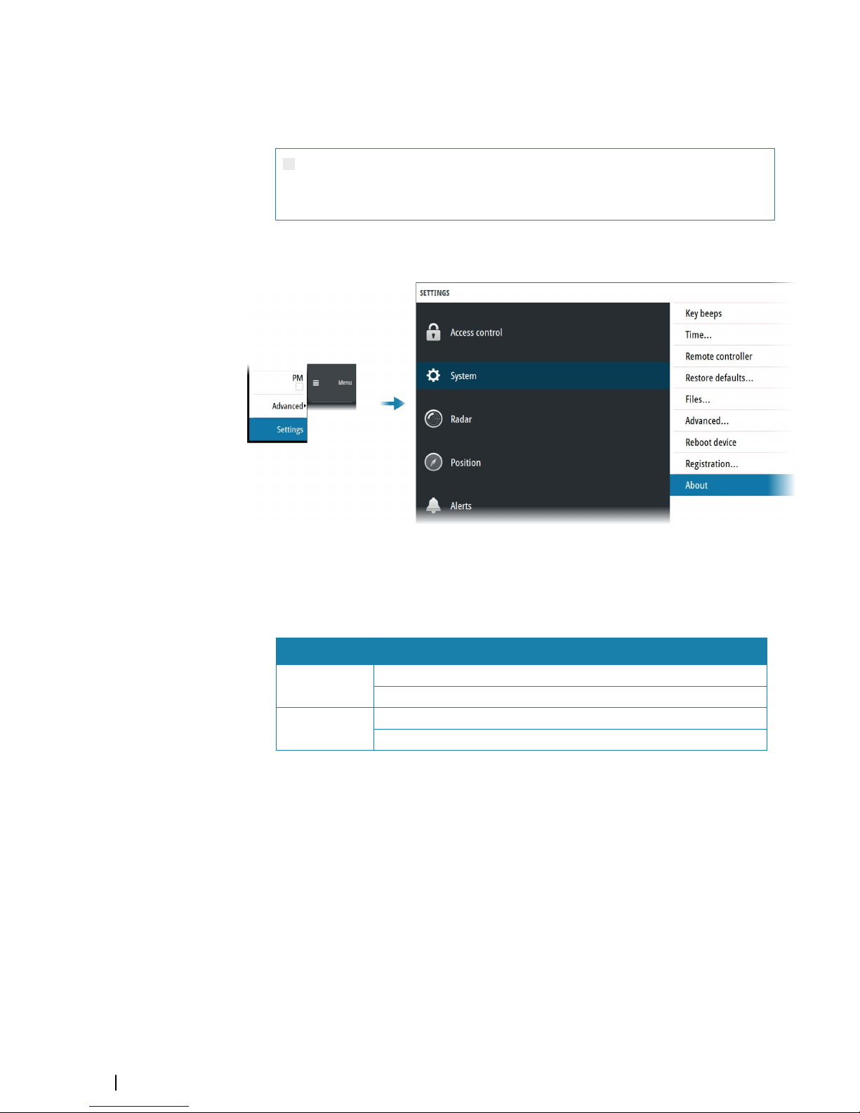
Software version
You can view the software version installed on the unit in the about dialog:
The manual will continuously be updated to match new software releases. The latest
available manual version can be downloaded from the product website on:
www.navico-commercial.com
Change log
Part no Date and description
988-12294-001
2018-Sept-19
First version.
988-12294-002
2018-Nov-01
Updated to match software release.
4
Preface | R5000 Operator manual
Page 5

Safety precautions
Safety precautions described in this section are applicable to the radar system. They are
general safety precautions that are not related to any specific procedure, and they might
therefore not appear elsewhere in this manual. They are recommended precautions that
personnel must understand and apply during operation and maintenance of the system.
You are obliged to read these operating instructions prior to operation, and to adhere to the
operating instructions in order to prevent possible danger. Prevention of danger includes
that operator personnel are trained and authorized for safe operation of the equipment. We
assume no liability for damage due to improper operation which could have been
prevented.
The system must only be operated by persons who have passed the relevant mandatory
training on the respective systems and applications. Only reading these operating
instructions cannot replace such training. Persons authorized to operate, maintain and
troubleshoot the system are instructed and trained by Simrad. Persons operating or servicing
this radar system must be familiar with the general safety regulations and specific safety
systems, and they must have passed all required training. They must have read the relevant
operating instructions and manuals before starting to work.
Have these operating instructions always at hand on all relevant locations, and ensure that
copies are available to all operators. Operating personnel must at all times follow all safety
regulations.
During normal operation, the unit can be quickly disconnected from the main power line by
turning OFF the relevant circuit breaker located on the electric switchboard.
Do not replace components or make adjustments inside the unit when the voltage supply is
turned ON. Always remove power and discharge to ground a circuit before touching it.
Under no circumstances should any person initiate servicing or repairing the unit except in
the presence of a qualified person.
Ensure unobstructed access to all operator panels, controls, and relevant switchgear cabinets
in order to enable instant response to alarms.
Whenever it is necessary to disconnect the waveguide from a radar transmitter for
maintenance purpose, the transmitter output should be terminated with a matched load. If
this is not possible, care should be taken. Do not stand in front of an open-ended waveguide
from which power is being radiated.
Ú
Note: Main power is always present on the terminal board unless the main break from
the power distribution panel of the vessel is turned off.
Warning: Never look down a waveguide from which power is being
radiated!
Warnings
High voltage
Radar equipment includes high voltage that can cause injury or loss of life. Danger exists only
when the units are opened, exposing internal circuits, as when servicing the equipment.
This radar has been carefully designed to protect personnel from possible injury from high
voltages. Although every effort has been made to eliminate danger to personnel, no
responsibility is accepted for any injury or loss of life suffered in connection with this
equipment.
Radio frequency radiation
Harmful effects (particularly to the eyes) may be caused by exposure of any part of the
human body to high power radio frequency radiation.
However, the system is designed to always disable the microwave radiation when the
antenna is not rotating.
Preface | R5000 Operator manual
5
Page 6

Hazard distances
Configuration
Distance 100 W/m
2
point (m)
Distance 50 W/m
2
point (m)
Distance 10 W/m
2
point (m)
12 KW Transceiver
6' X-band Antenna
- 0.15 0.6
12 KW Transceiver
9' X-band Antenna
- - 0.5
12 KW Transceiver
12' X-band Antenna
- - 0.35
25 KW Transceiver
6' X-band Antenna
0.1 0.2 1.3
25 KW Transceiver
9' X-band Antenna
- 0.1 1.0
25 KW Transceiver
12' X-band Antenna
- 0.05 0.9
30 KW Transceiver
12' S-band Antenna
- - 0.4
X-Ray radiation
This radar system does not generate X-ray radiation.
6
Preface | R5000 Operator manual
Page 7

Contents
10 Introduction
10 R5000 system overview
10 R5000 manuals
12 Operating the system
12 O5000 trackball mouse keys
12 O2000 front controls
14 M5000 monitor keys
15 The user interface
15 Main panel
16 PPI symbols
16 Picture freeze indicator
16 Quick access buttons
16 Main menu and submenus
17 The settings dialog
17 Own vessel symbol
17 Units of measure settings
18 Radar video palettes
18 On-screen keyboard
19 Basic operation
19 Turning the system ON and OFF
19 Adjusting display brightness
19 Selecting radar source
19 Switching the sensor between transmit and standby mode
19 Adjusting the radar range
20 Using the cursor
20 Selecting speed source
22 Target tracking
22 Acknowledging alerts
23 Applying default control settings
23 Screen capture
24 The Interswitch function
24 Description
24 Default master control station
24 Control station modes
25 Changing control mode
26 Indication of control status
27 Adjusting the radar image
27 Fine tuning automatic settings
27 Gain
27 Sea anti-clutter
28 Rain anti-clutter
29 Tuning the radar sensor
30 Radar view options
30 Target trails and past position
30 Radar orientation
30 Radar motion mode
31 Offsetting the PPI center
32 Vectors
32 Cursor bearings
32 Setting the brilliance for panel items
Contents | R5000 Operator manual
7
Page 8

33 Targets
33 The target menu
33 The target panel
33
Selecting and de-selecting targets
34 Defining dangerous vessels
34 Radar targets
37 Radar SART
38 Racons
39 AIS targets
41 AIS and radar target association
42 Displaying target information
43 Training simulator
44 Navigation tools
44 Tracking zones
45 Parallel index lines
46 EBL/VRM markers
48 Measuring range and bearing
50 Maps
50 The maps dialog
50 Map references
51 Map colors and symbols
51 Creating a new map
52 Saving a map
52 Modifying a map
53 Exporting maps
53 Importing maps
54 Customizing radar control settings
54 Customizing radar control settings table
55 Advanced options
55 Rejecting radar interference
55 Noise rejection
55 Target boost
55 TGT expansion
55 Fast scan
56 Trial maneuver
56 Trial maneuver symbology
57 Starting and stopping the trial maneuver
57 Manually changing the trial maneuver settings
58 Maintenance
58 General
58 Performance monitor
59 Radar data
60 The alert system
60 Type of alerts
60 Alert categories
60 Alert notifications
63 The Alerts dialog
63 External bridge alert systems
64 Alphabetic alert list
65 Operating modes fallback
8
Contents | R5000 Operator manual
Page 9

66 Menu overview
66 Main menu
67 Settings menu
69
O2000/O5000 Trackball, key function comparison
70 Target symbols
73 Terms and abbreviations
78 Technical specifications
78 General
78 Performance
79 Display features
79 Target tracking
80 AIS
80 Mapping
Contents | R5000 Operator manual
9
Page 10
Introduction
R5000 system overview
A basic R5000 radar system has the following main parts:
• SRT LAN radar sensor (A), including:
- Antenna
- Up-mast or down-mast SRT LAN transceiver
-
R5000 power supply unit
• R5000 radar control station (B), including:
- M5000 monitor
- O2000 control unit
- O5000 trackball unit
- R5000 radar processor
A A
B
B
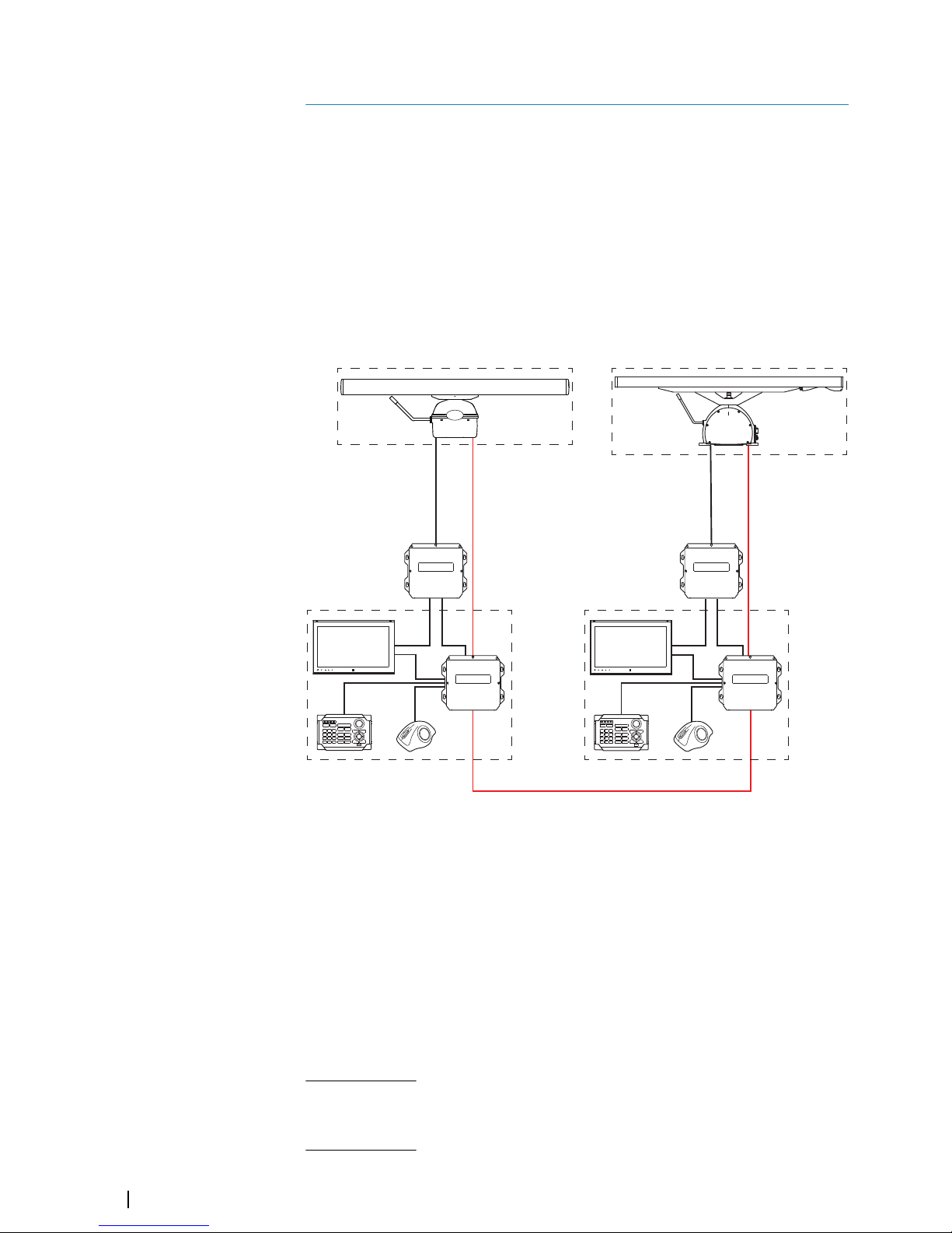
An R5000 system can be installed as a stand-alone radar system, or as an advanced
installation with several sensors and control stations.
In an advanced installation, each radar sensor has a control station directly wired to it. This
control station will be the radar sensor's default master controller. The R5000 radar
processors can be connected with an interswitch LAN cable. This allows for sharing the
control of the radar sensors between multiple radar control stations. During commissioning
of the system, the interswitch function is configured to manage the control of the radar
sensors. For more information, refer to "The Interswitch function" on page 24.
R5000 manuals
The following documentation is available for the R5000 radar systems:
R5000 Operator manual
User descriptions of the radar control unit and of the features included in the system.
Intended audience: System operator.
R5000 Quick Guide
Graphical document describing the keys and the main functions.
Intended audience: System operator.
1
10
Introduction | R5000 Operator manual
Page 11

R5000 System installation manual
Mechanical installation and wiring, technical specifications and mechanical drawings for all
system components.
Intended audience: Shipyard installation personnel.
R5000 Configuration manual
System setup/configuration and commissioning of the system.
Intended audience: Installation and service engineers.
Introduction | R5000 Operator manual
11
Page 12
Operating the system
The system is operated by the remote control unit (O2000) and by the mouse (O5000
Trackball unit).
The remote controller is used for menu operation, and for easy operation of the quick access
buttons.
The mouse is mainly used for managing targets, and in situations where it is required to
position the cursor accurately on the PPI.
For a full overview of remote controller and mouse keys, refer to "O2000/O5000 Trackball, key function
comparison" on page 69.
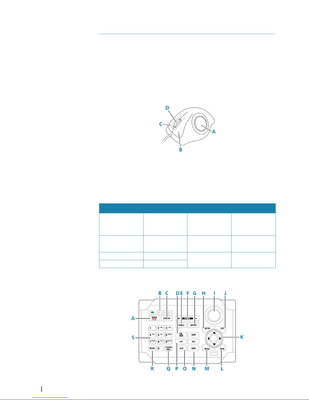
O5000 trackball mouse keys
The optical trackball (A) is used for positioning the cursor. The other mouse keys have
different functionality depending on the position of the cursor on the radar panel.
The following table lists the key functions relative to the part of the radar panel that is under
the cursor.
Ú
Note: The cursor must be located over an open menu or over the quick access pop-up
to be able to use the scroll function.
Cursor over ... Left key (B) Right key (C) Scroll wheel (D)
Menu Select
Return to previous
menu level
• Rotate to scroll
menu options
• Press to select
Quick access button Select
Display selected
button's pop-up
• Rotate to scroll
pop-up options
AIS target Activate/deactivate
Display target menu No action
Radar target Acquire target
O2000 front controls
2
12
Operating the system | R5000 Operator manual
Page 13

Ú
Note: The O2000 can be used with different equipment. As noted below, some of the
keys are not applicable for the R5000.
A Mark/MOB key. Not used for R5000
B Unit under command LEDs. Not used for R5000
C Display key. Used for configuration of the O2000. Not used for operating the R5000
D EBL/VRM key. Press once to toggle EBL/VRM markers On/Off. Re-press to display
the EBL/VRM pop-up. Press and hold to toggle between EBL/VRM 1 and EBL/VRM
2.
E Trails key. Press to toggle trails ON/OFF.
F Range key. Press the + or the - indication to increase or decrease the radar range
G Offset key. Press once to display the Offset menu
H Enter key. No cursor on PPI: no action. Cursor on PPI: press to activate/deactivate
AIS, press and hold to display the targets menu.
Menu operation: press to select an option
I Rotary knob. With no menu active: behavior depending on operational mode.
Menu operation: rotate to scroll through menu items and to adjust values, press to
select or to save settings
J Exit key. With no menu active: clear the cursor from the PPI. Menu operation: press
to return to previous menu level or to exit a dialog
K Arrow keys. With no menu active: press to move the cursor on the radar PPI.
Menu operation: press to move through menu items and to adjust a value
L View key. Press once to display the View menu
M Menu key. Press once to display the Main menu
N Gain, Sea, and Rain keys. Press to set radar sensitivity
O Acknowledge key. Press once to acknowledge the most recent alarm or warning in
the Alerts panel. Press the key again to acknowledge the next alarm or warning.
Press and hold to bring the focus on the Alerts panel without acknowledging the
most recent alarm
P AIS key. Press to activate/deactivate AIS information on screen. Press and hold to
display the Vessels dialog
Q Standby/Brilliance key. Press once to display the Standby/Brightness pop-up. Press
twice to toggle between Standby and Transmit. Press and hold to switch the radar
system ON/OFF.
R Mode key. Not used for R5000
S Alpha numeric keypad. Used for entering numbers or text in dialog boxes. With no
menu active: press a key to modify the range as shown below:
1 2 3 4 5 6 7 8 9 0
NM 1/8 1/4 1/2 3/4 1.5 3 6 12 24 48
Operating the system | R5000 Operator manual
13
Page 14
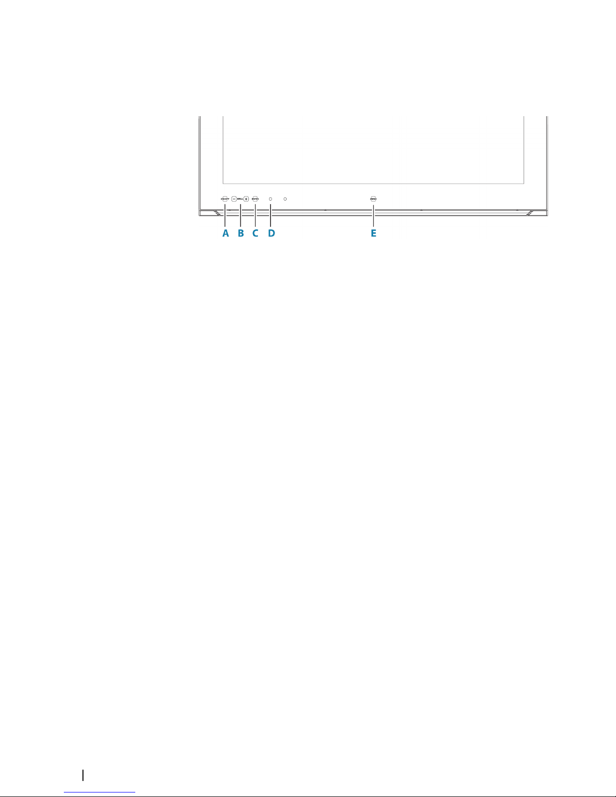
M5000 monitor keys
The monitor is configured and controlled using the row of touch sensitive buttons along the
lower edge of the monitor frame. All buttons are backlit - only the power button is
illuminated when the monitor is turned off.
A Power key
• With OSD (On Screen Display) menu active: press to return to previous menu
level
• With no OSD menu action: no action
B Brilliance adjustment key
• Press plus/minus key to decrease/increase brightness (no on-screen display of
brightness level)
• Simultaneously press and hold both keys to reset the brightness level to default
value. The default value is set in the OSD menu
• With OSD menu active: press plus/minus key to move focus up/down in the
menu
C Enter key
• With OSD menu active: press to confirm a selection
• With no OSD menu active: no action
D Red LED
• Solid on: standby mode, or no video source
• Flashing: monitor booting or upgrading
E Menu key
• Press and hold to activate the OSD menu
For more information, refer to the separate documentation for the monitor.
14
Operating the system | R5000 Operator manual
Page 15
The user interface
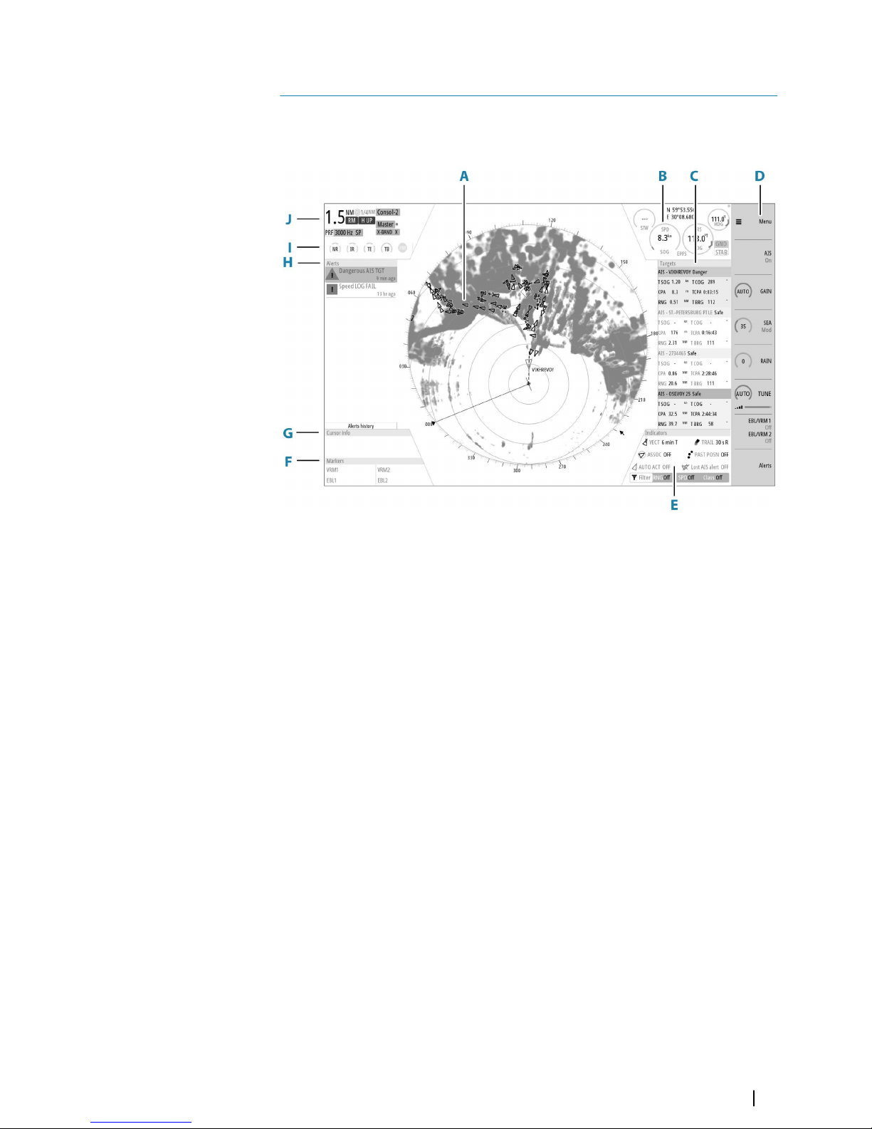
Main panel
The main panel is divided into predefined areas as shown in the figure below.
A Plan Position Indicator (PPI)
Radar video area where all tracking and navigation options are performed.
B Own ship information
Stabilization mode indicator, picture freeze indicator and gauges showing primary
and secondary sensors.
C Target panel
Detailed information about selected targets and AIS targets.
D Quick access buttons
Dedicated buttons for main function.
E Target indicators
Overview of target indicator settings.
F Markers
Details for active VRM and EBL markers.
G Cursor information
Range and bearing from the vessel to the cursor position. Also including position
information if a position source is available.
H Alerts panel
List of all active alerts.
I Signal indicators
Gauges for signal processing and indicators for radar functions.
J System information
Range, mode and pulse details.
3
The user interface | R5000 Operator manual
15
Page 16
PPI symbols
Range rings and heading line symbols can be turned on and off individually.
For parallel index lines and maps, see "Parallel index lines" on page 45 and "Maps" on page 50.
The overlay graphic off menu option turns off all graphics overlaid on the radar PPI, showing
only the video signal.
Ú
Note: The heading line off and overlay graphic off menu options are mono stable. That
means you have to press and hold the enter key or the right arrow key to temporarily
remove the relevant symbols from the panel. The graphics are invisible as long as the key
is pressed, and will turn on again when the key is released.
Picture freeze indicator
The image includes a picture freeze indicator (A). The small dot blinks at an interval of 1
second to show that the screen is alive and that information from sensors is updated.
If the picture freezes the unit needs to be restarted.
Quick access buttons
The quick access buttons are activated from the dedicated keys on the controller, or by using
the mouse to select the button.
More details about the quick access buttons are available in the separate sections describing
the functions later in this manual.
Quick access pop-ups
Some of the quick access buttons have additional functions, presented as a pop-up.
To display the pop-up:
• Double-press the dedicated key on the controller
• Press the right mouse key when the cursor is over a selected quick access button
To remove the pop-up and revert to the button's main function:
• Press the exit key on O2000
• Press the left mouse key when the cursor is outside the pop-up
• Press the right mouse key when the cursor is over the pop-up
Main menu and submenus
You access the main menu by pressing the menu key, or by selecting the quick access menu
button.
To operate the menu with the O2000:
• Press the up and down arrow keys or turn the rotary knob to move up and down in a
menu
• Press the enter key, the right arrow key or the rotary knob to access a submenu, to toggle
options or to confirm a selection
• Press the exit key or the left arrow key to return to previous menu level and then exit the
menu system
Some options display a slider. Turn the rotary knob or press the up/down arrow keys to
adjust the value.
To use the trackball mouse to operate the menu:
• Use the scroll wheel to move up and down in a menu
• Use the left key to access a submenu, to toggle options or to confirm a selection
16
The user interface | R5000 Operator manual
Page 17
• Use the right key to return to previous menu level and then exit the menu system
Ú
Note: The cursor must be located over the menu to operate the menu system.
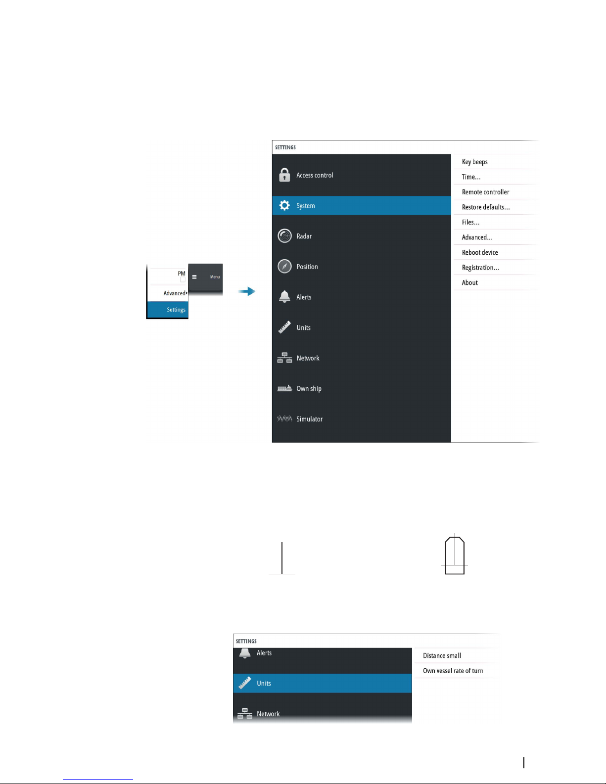
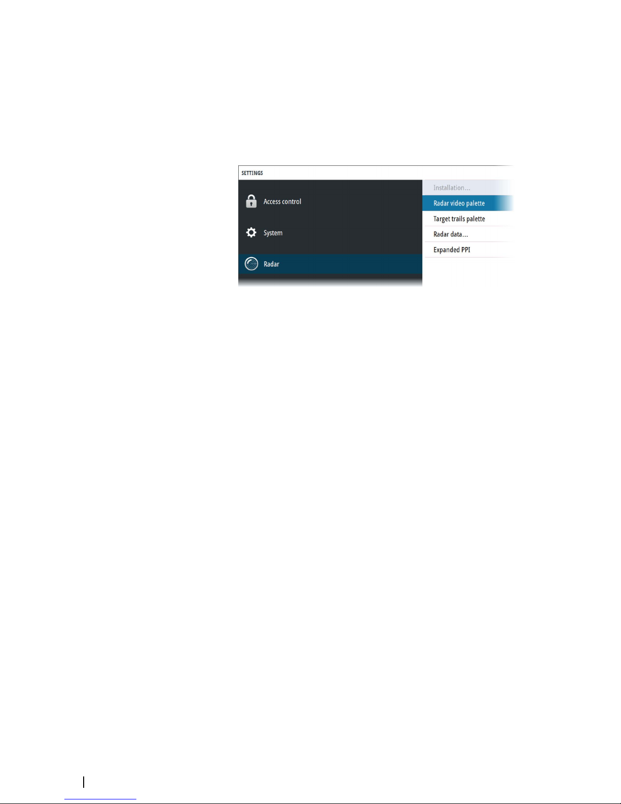
The settings dialog
The software setup is done from the settings dialog.
Own vessel symbol
At large range scales, the indication of antenna position, the CCRP and own vessel are the
same, and indicated as an own ship minimized symbol.
At small range scales, the vessel's actual size (defined in the commissioning of the radar
system) is indicated. If the antenna position deviates from the CCRP this will be shown on the
image.
Vessel symbol at large range scale Vessel symbol at small range scale
Units of measure settings
The user interface | R5000 Operator manual
17
Page 18
By default, speed measurements are in knots (kn), and large range measurements are in
nautical miles (NM). These settings cannot be changed.
For distances below 0.125 NM you can select to show the distance in meters.
Ú
Note: Units of measurements can only be changed when the connected antenna is in
standby mode.
Radar video palettes
Different palettes are available for the radar video and for the target trails.
Expanded PPI
With this option selected, the radar video outside the bearing scale is visible as a shaded
image. Targets, VRM and Range rings are not visible in the expanded PPI area.
On-screen keyboard
A numeric or alphanumeric virtual keyboard is displayed when required to enter user
information in dialogs.
To enter text:
• Use the arrow keys to locate the cursor over a virtual key, then confirm the selection with
enter key
• Select a virtual key with the left mouse key
If the virtual keyboard is inactive for 10 seconds it will automatically close.
Complete the entry and close the dialog by selecting the virtual enter key.
Remove the virtual keyboard without saving by pressing the exit key.
18
The user interface | R5000 Operator manual
Page 19
Basic operation
Turning the system ON and OFF
Turning ON
Press the standby/brilliance key to turn the system ON.
The system will be ON as long as power is connected.
Switching the system to standby mode
Press and hold the standby/brilliance key to turn the R5000 radar processor and the monitor
to standby mode. The radar sensor is turned into standby mode only if R5000 is controlling it
(connected as master). If it is in slave/clone mode, the sensor will continue transmitting.
Ú
Note: For controlling the radar sensor in a multi-radar installation, refer to "The Interswitch
function" on page 24.
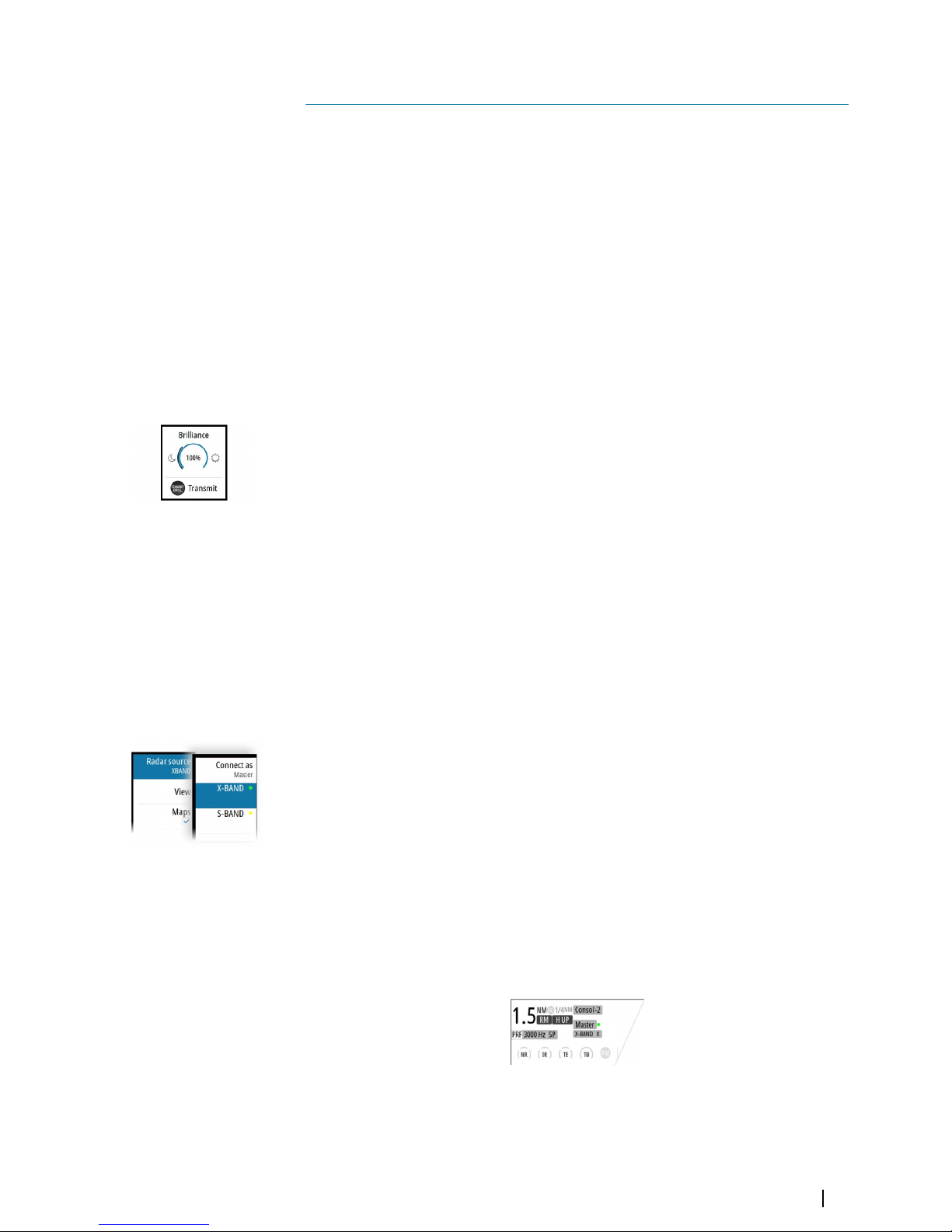
Adjusting display brightness
The brilliance is adjusted from the brilliance pop-up.
• Display the pop-up by pressing the standby/brilliance key, then adjust the display
brilliance by turning the rotary knob.
At first start-up, the display brilliance is set to 100%. When the unit is restarted, the brilliance
is automatically set to the level it was prior to switching the unit off.
The system includes a day and a night color palette. When the brilliance is set to 40% or
lower, the system switches to use the night palette.
• With the pop-up open, switch between the day and night palette by pressing the left
(40%) or right (100%) arrow keys.
Close the pop-up by pressing the exit key.
This brightness adjustment affects all screen items on the radar panel. You can also adjust the
display brightness for individual panel items. Refer to "Setting the brilliance for panel items" on page
32.
Selecting radar source
More than one radar sensor can be connected to the radar control unit.
Select the active radar sensor from the main menu.
For information about controlling radar sensors in a multiple radar installation, see "The
Interswitch function" on page 24.
Switching the sensor between transmit and standby mode
You switch between transmit and standby mode when the brilliance pop-up is displayed.
• Display the pop-up by pressing the standby/brilliance key, then repeat short presses on
the key to switch between standby and transmit mode
Adjusting the radar range
The radar range is shown in the system information area on the radar image.
To increase or decrease the range:
• Press the + or - icons on the range key
• Select a predefined radar range by using the numeric keys on the remote controller. Refer
to "O2000 front controls" on page 12.
4
Basic operation | R5000 Operator manual
19
Page 20
There is a direct link between the range scale and the operational mode of the selected radar
sensor.
Range scale
Standard radar operation Target boost radar operation
A B A B
1/8 NM (200m) 0.08/3000 24 0.08/3000 24
1/4 NM 0.08/3000 24 0.08/3000 24
1/2 NM 0.08/3000 24 0.08/3000 24
3/4 NM 0.08/3000 24 0.08/3000 24
1.5 NM 0.08/3000 24 0.08/3000 24
3 NM 0.08/3000 24 0.25/1500 48
6 NM 0.25/1500 48 0.25/1500 48
12 NM 0.25/1500 48 0.8/750 72
24 NM 0.8/750 72 0.8/750 72
36 NM 0.8/750 72 0.8/750 72
48 NM 0.8/750 72 0.8/750 72
64 NM 0.8/750 72 0.8/750 72
72 NM 0.8/750 72 0.8/750 72
A: Pulse length (µS/PRF (Hz)
B: Maximum radar range visibility (NM)
For more information refer to the radar sensor documentation.
Using the cursor
The cursor can be used to measure a distance, to define various radar map elements, and to
acquire and select targets within the PPI area.
By default, the cursor is not active after power on.
To activate the cursor:
• Press one of the arrow keys
• Use the mouse to position the pointer inside the PPI area
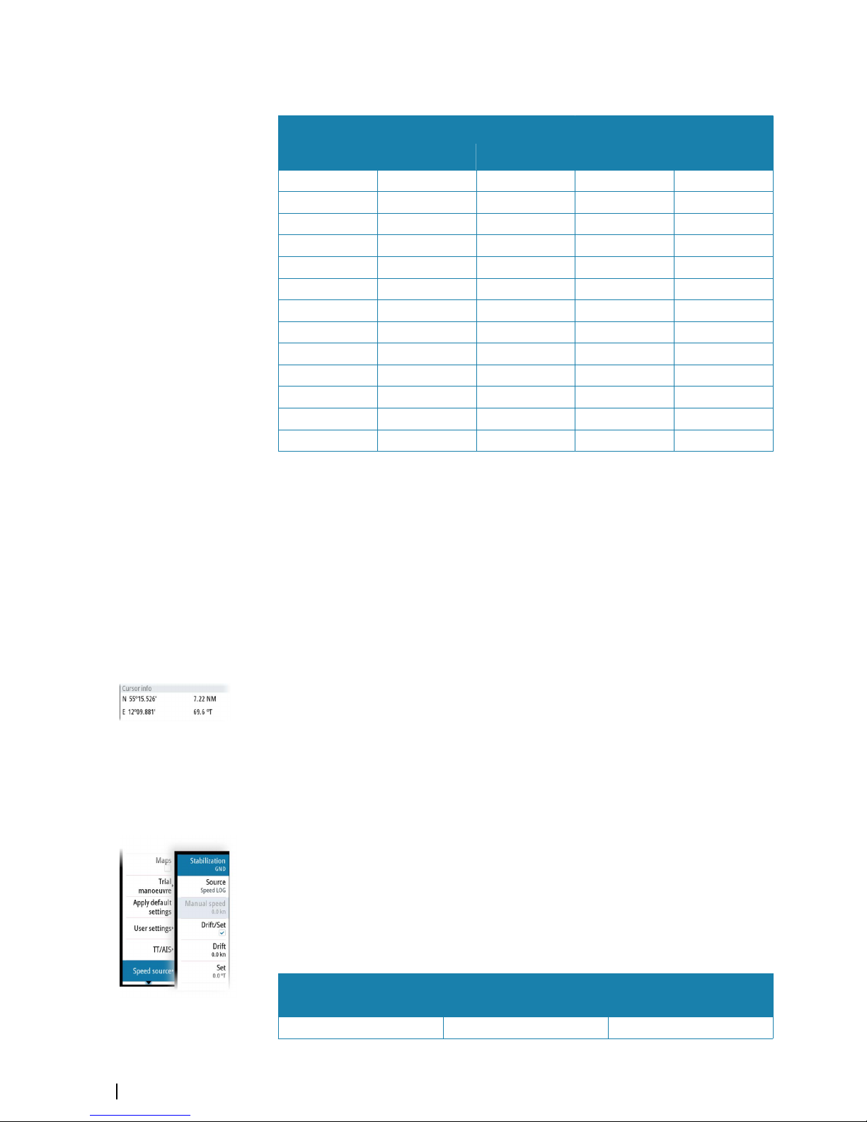
When the cursor is active on the radar PPI, the cursor information area will show range and
bearing from the vessel to the cursor position. If the system is connected to a position source
(i.e. EPFS), the cursor information area includes the geographic position of the cursor.
To deactivate the cursor:
• Press the exit key
• Use the mouse to position the pointer outside the PPI area
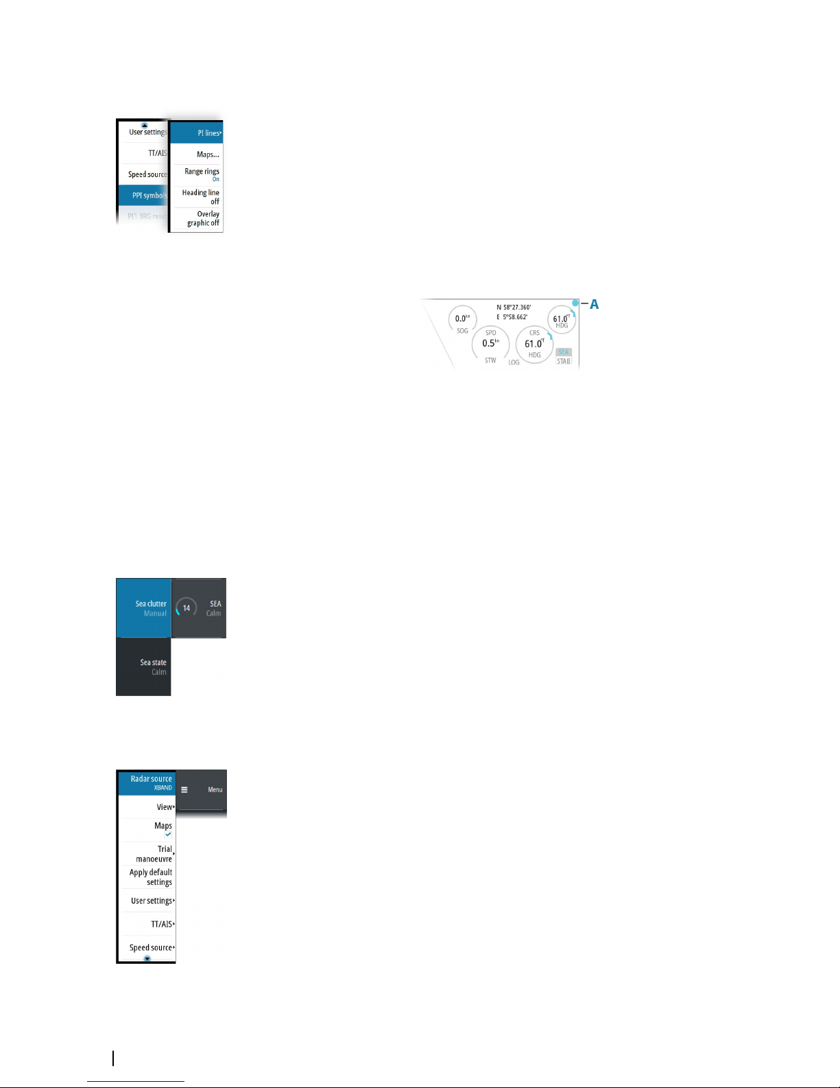
Selecting speed source
Speed information can be obtained from different speed sources connected to the system.
At any time you can switch the preferred primary speed source to any of the available speed
sensors from the menu.
The stabilization mode depends on the selected speed source. The system will automatically
switch to the available stabilization mode when the speed source is changed.
The table shows stabilization modes available for each speed source type. Any restrictions for
a source are detailed under each speed source description in the following sections.
Speed source
Stabilization mode
available
Restrictions
Speed LOG (Single axis) Sea None
20
Basic operation | R5000 Operator manual
Page 21
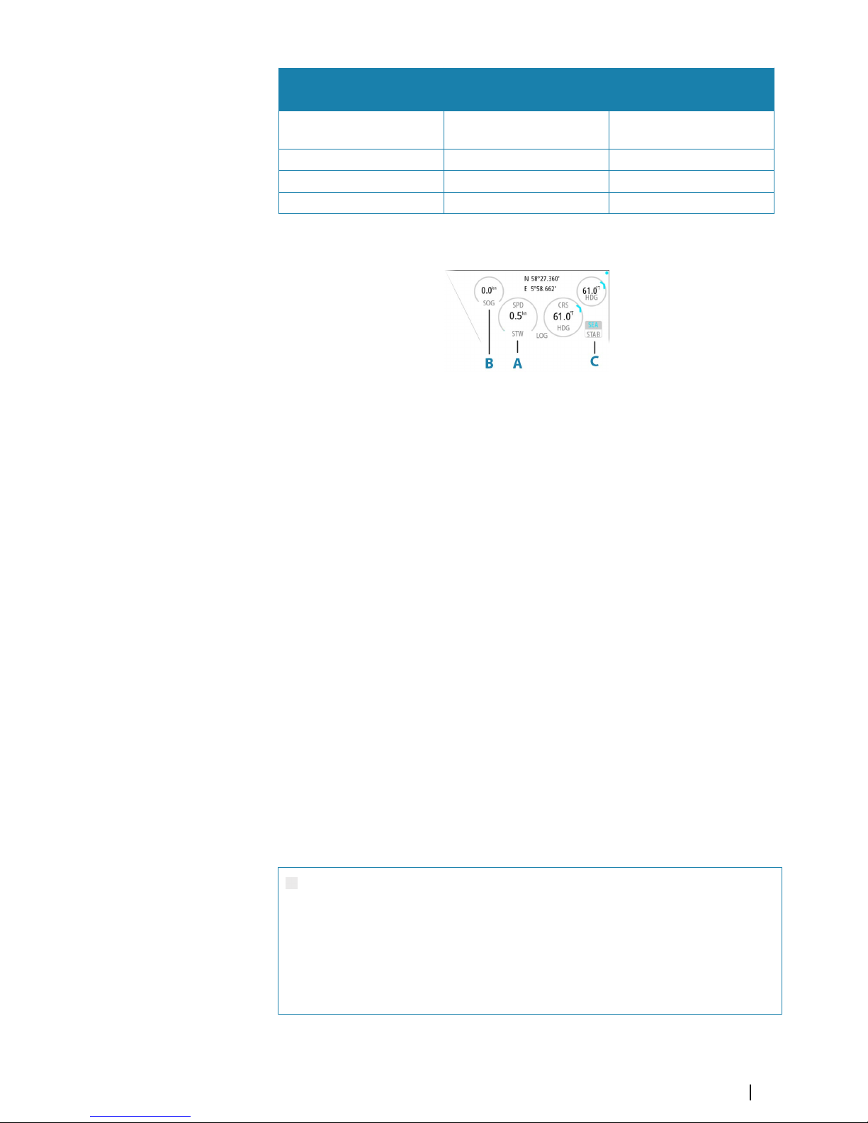
Speed source
Stabilization mode
available
Restrictions
Speed LOG (Dual axis)
Sea and Ground (depending
on the transducer)
None
EPFS Ground None
Manual Sea Yes
Auto drift Ground Yes
Primary speed source (A), secondary speed source (B) and stabilization mode (C) are shown
in the own ship information panel.
Ú
Note: In case of unsafe data integrity the vessel coordinates are highlighted with yellow
color.
Speed log
The speed log can be single or dual axis input, and either water track or bottom track.
Therefore the stabilization mode available can be either sea or ground depending on the
sensor in use.
Ú
Note: The speed through water measured close to the hull is affected by the tide and by
the current, so from time-to-time it will differ significantly from the speed over the
ground. A speed log measuring speed through water may, in specific cases, be affected
by poor conditions due to e.g. air or ice below the sensor. If the sensor measures only the
longitudinal component of the speed, the transversal ship component is unknown to
the radar.
EPFS
The EPFS provides true speed and true course over ground.
Manual speed
When this option is selected you can manually enter speed, drift and set (heading).
Ú
Note: Manual speed is not available if AIS is turned ON.
Auto drift
When this option is selected the system uses a stationary tracked target as speed reference
for calculating own ship speed. The function is used when no speed sensors are available.
Ú
Note: The auto drift option is only available if the AIS function is OFF and if a target is set
as reference.
Warning: The echo used as reference must be a stationary target.
Otherwise all speed calculated will not be true, but only relative to the
reference target. It is wrong to select a ship that is anchored as a reference;
no alarm will be signaled when the ship starts to move and all the
calculated true speed will change to erroneous values. The reference echoes
should never be used to calculate relative speed. This data is not following a
speed change with adequate accuracy for an anti-collision system.
Basic operation | R5000 Operator manual
21
Page 22
Warning: When the reference target is lost, a warning is raised and the
speed source will automatically be switched to LOG. If the LOG is working
on water track, the speed mode will become sea stabilized and the user will
be notified in case of a change of stabilization. The loss of a reference target
may have a major impact on the accuracy of the results for true speed and
true course of the target, and own speed precision will be degraded.
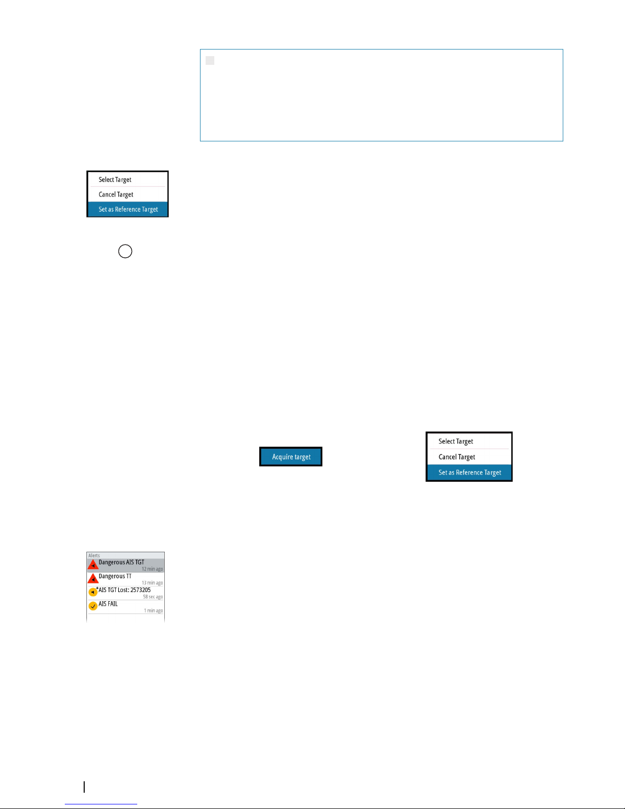
Selecting a reference target
A reference target must be selected before the speed source can be set to auto drift. The
reference target is selected from the target menu.
To display the target menu, position the cursor over the preferred target and then:
• Press the enter key
• Press the right mouse key
The reference target is labelled with an R to identify it as a reference.
Target tracking
The enter key on O2000 and the mouse keys are used for managing targets.
To immediately acquire a radar target or to activate/de-activate an AIS target at the cursor
position:
• Press the enter key
• Press the left mouse key
More options are available from the target menu, displayed by:
• Pressing and holding the enter key
• Pressing the right mouse key
The options in the target menu depends on if a target is located at the cursor position, the
type of target, and the status of the target.
No target at cursor position
Target at cursor position
See more details about radar and AIS targets in "Targets" on page 33.
Acknowledging alerts
To acknowledge the most recent alert:
• Press the acknowledge key
The focus is moved to the alerts panel.
Repeat pressing the key to continue acknowledging alerts from the top of the alerts panel.
Press the exit key to exit the alerts panel.
When an alert is acknowledged, the alert icon stops flashing and changes to the
acknowledged icon. The siren continues to sound if there are remaining unacknowledged
alerts, otherwise it is muted.
The acknowledged alert is not moved to its new position in the sort order until there has
been 2 seconds without any alerts being acknowledged.
For more details, refer to "The alert system" on page 60.
R 18
22
Basic operation | R5000 Operator manual
Page 23

Applying default control settings
The apply default settings option allows for quickly setting the system back to a predefined
state. The predefined values are defined in the radar requirements standard.
Refer "Customizing radar control settings" on page 54.
Screen capture
To take a screen capture:
• Simultaneously press the enter key and the standby/brilliance key
Screen captures are saved to internal memory.
Basic operation | R5000 Operator manual
23
Page 24
The Interswitch function
Description
The interswitch function allows for sharing a radar sensor between multiple radar control
stations.
Default master control station
The control station directly connected to a sensor shall always be that sensor’s default
master. A default master has top priority over all other control stations in the interswitch
network, and can assume master control for this sensor at any time.
In the event of an interswitch network failure, the control station and the directly wired
sensor will operate as a standalone radar.
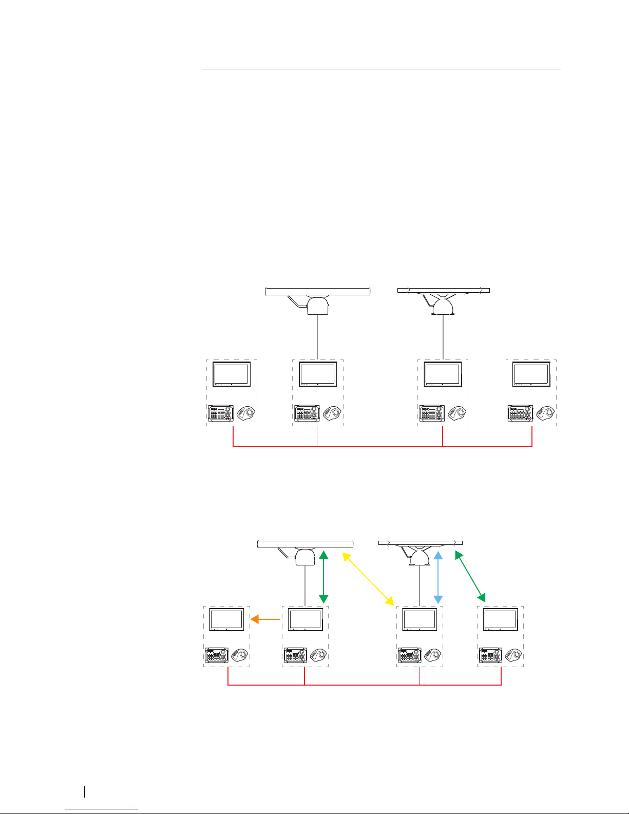
The illustration shows an installation with 2 sensors and 4 control stations. The control
stations are connected via the interswitch network. In this example, sensor A is directly wired
to control station C. Control station C is then by default sensor A's default master. The same
applies to sensor B and control station D.
AA
CC DD
BB
Control station modes
The control station can have different control modes for the sensors connected via the
interswitch network.
The illustration shows an example of control modes for an installation with 2 sensors and 4
control stations.
CC
MM
MM
MRMR
SS
M Master mode
MR Master mode requested
S Slave mode
C Clone mode
5
24
The Interswitch function | R5000 Operator manual
Page 25

Master
A master control station has full control of a radar sensor.
There can be only one master for each sensor at a given time. A control station has to release
its master status before another control station can be set to master mode.
To release master control:
• Change the status from the menu. Refer to "Changing control mode" on page 25
• Turn the radar sensor to standby mode from the brilliance pop-up
• Turn the control station to standby mode by pressing and holding the standby/brilliance
key
When a control station request master control of a radar sensor, the transfer will be pending
until the current master has released its master status. When master mode for the sensor is
available, the control will switch automatically.
If more than one control station request master control of a radar sensor, the control transfer
is decided according to the priority table defined during setup of the system.
Slave
A slave control station has restricted control of the radar sensor.
There can be max 3 slaves for each radar sensor simultaneously.
Slave mode limitations
A slave cannot access:
• Radar transmission controls
• Performance monitor
• Radar tuning
If a master is available for the same sensor, a slave has limitations for the following functions:
• Transmit ON and OFF: only possible if the sensor is set to transmit on the master control
station
• Radar range: the maximum radar range on a slave cannot exceed the range set on the
master control station
Ú
Note: The slave control station can disable its radar presentation by pressing the
standby/brilliance key on the O2000.
Clone
A clone control station mirrors a selected control station’s display. A clone cannot control a
radar sensor.
If the console that is controlling the radar sensor is disconnected, the clone will lose the
connection to the radar sensor. The clone will have to manually select a new sensor.
There can be multiple clone stations for each control station simultaneously.
Changing control mode
To request a control mode for a sensor from a control station:
1 Select the status you want to request (A)
2 Assign the status to a sensor (B)
The Interswitch function | R5000 Operator manual
25
Page 26

The color indication (C) for the sensors shows if a control station can be connected as the
master for a sensor:
• Green: the sensor is available for master control
• Yellow: another control station has master control of the sensor
You can also request master or slave control mode from the sensor network status dialog.
Indication of control status
The control station’s operational mode (A) for the active radar sensor (B) is indicated in the
system information panel.
26
The Interswitch function | R5000 Operator manual
Page 27

Adjusting the radar image
The radar image can be improved by adjusting the gain, by filtering out unwanted echoes
due to sea clutter, rain or other weather conditions, and by tuning the sensitivity of the radar
receiver.
Some functions include both a manual and an automatic mode. It is recommended to use
the manual mode only if the automatic mode does not provide satisfactory results.
Ú
Note: The radar image settings do not affect the AIS targets.
Sea and rain clutter could be present at the same time, and further degradation in detection
performance will be experienced. As sea clutter is related to short range and rain clutter is
usually present in a longer range, rain clutter settings can be adjusted without affecting the
echoes in the sea clutter area.
Long pulses should not be used in heavy rain, as the range will decrease significantly. See
"Performance limitations" on page 28.
The radar image is controlled as described in the next sections.
Ú
Note: It is recommended to turn trails off when you adjust the radar image as trails
might hinder the proper video adjustment feedback.
Fine tuning automatic settings
Some radar settings include an automatic mode.
To achieve the best possible result in auto mode, the value can be manually adjusted to fine
tune the settings. The text within the control icon will then change from AUTO to A ± NN,
indicating that the automatic setting is manually adjusted.
To fine tune the automatic setting:
• Turn on the automatic option
• Use the rotary knob or the arrow keys to manually adjust the setting
Gain
The gain option controls the sensitivity of the radar receiver. A higher gain makes the radar
more sensitive to radar echoes, allowing it to display weaker targets. If the gain is set too
high, the image might be cluttered with background noise.
Ú
Note: The gain control shall not be used to clean the picture from sea or rain clutter.
The value of the gain should be set so that the background noise is just visible on the radar
panel.
At start-up of the system, the gain is 80% in order to receive the optimum noise level.
Gain has a manual and an automatic mode.
Adjusting the gain
To adjust the gain:
• Press the gain key to activate the function, then turn the rotary knob to manually adjust
the setting
• Press and hold the gain key to turn on/off the automatic option
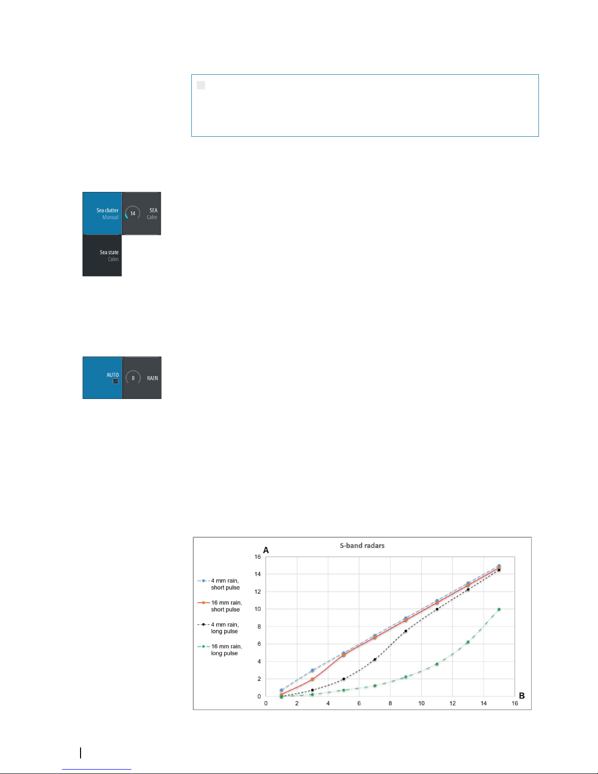
Sea anti-clutter
The sea anti-clutter option is used to filter the effect of random echo returns from waves or
rough water near the vessel. When you increase the value, the sensitivity of the near field
clutter caused by waves is reduced. If the value is increased too much, both sea clutter and
6
Adjusting the radar image | R5000 Operator manual
27
Page 28
targets will disappear from the display. Targets around own ship may then not be shown as
potentially dangerous targets.
Warning: At increasing levels of sea clutter, some targets cannot be
detected even by means of the sea anti-clutter filtering, since buoys or other
small objects are producing echoes of a level lower than the ones coming
from waves.
The value of the sea anti-clutter should be set so that the clutter is seen as small dots, and
small targets will become distinguishable around the ship.
Sea anti-clutter has a manual mode and an automatic mode. The system includes predefined
settings for calm, moderate and rough sea state conditions.
Adjusting the sea anti-clutter
To adjust the sea anti-clutter:
• Press the sea key to activate the function, then turn the rotary knob to adjust the setting
• Press and hold the key to turn ON/OFF the automatic option
Rain anti-clutter
Rain anti-clutter is used to reduce the effect of rain, snow or other weather conditions on the
radar image. When you increase the value, the sensitivity of the long distance field clutter
caused by rain is reduced. The value should not be increased too much as this may filter out
real targets.
If the precipitation is located over the ship's position, the adjustment of rain clutter will affect
the presentation of near echoes.
Rain anti-clutter has a manual and an automatic mode.
Adjusting the rain anti clutter
To adjust the rain anti-clutter:
• Press the rain key to activate the function, then turn the rotary knob to adjust the setting
• Press and hold the key to turn ON/OFF the automatic option
Performance limitations
The figures below show how the amount of rain and pulse length affect the detection range
(in NM) for X-band and S-band radars.
The vertical axis (A) is reduction of range for first detection of a target. The horizontal axis (B)
is the original range for first detection of a target.
As an example for long pulse length: a target that can be detected at 10 NM can only be
detected on 3 NM with 16 mm rain.
28
Adjusting the radar image | R5000 Operator manual
Page 29

Tuning the radar sensor
You can tune the radar sensor to show maximum target returns on the screen.
Tuning has a manual and an automatic mode.
In automatic tuning mode, system performs a tuning of the radar sensor when the range
scale changes.
Manual tuning should only be used if the automatic tuning fails. The tuning should not be
performed earlier than 10 minutes after the radar has been switched on. Manual tuning is
best done by a long pulse setting (range set to 24 NM), and by using a high level of gain. In
this condition, adjust the tuning control to obtain the maximum signal strength.
Adjusting the tuning
The O2000 remote controller has no dedicated tune key. Adjust the tuning by using the
mouse, or by using a combination of the mouse and the remote controller:
• Select the tune quick access key to activate the function, then use the scroll wheel or the
rotary knob to adjust the setting
• Press the left mouse key twice to turn ON/OFF the automatic option
Adjusting the radar image | R5000 Operator manual
29
Page 30

Radar view options
Several radar view options are available from the menu.
Ú
Note: The motion mode and offset options are disabled at max zoom range (72 NM).
The functions are enabled again when zooming down one level.
Target trails and past position
You select how the radar targets are displayed on the radar image in the trails and past
position submenu. See "Display settings for radar targets" on page 35.
Radar orientation
Selected radar orientation is shown in the system information panel (A).
Head-up
In head-up mode, the heading line on the PPI is oriented on the 0° on the bearing scale and
towards the top of the screen. The radar image is displayed relative to own ship, and when
the ship turns the radar image rotates.
Ú
Note: Head-up is only available in relative motion mode, and it is the only orientation
mode available if the radar is not connected to a heading source.
North up
In north up mode, the 0° indication on the PPI represents north. The heading line on the PPI
is oriented according to own ship heading obtained from the gyro compass. When the ship
turns the heading line changes its direction according to the ship's heading, while the radar
image remains stabilized.
The north up orientation is not available if no heading source is connected to the radar. If
heading data is lost, the system will automatically switch to head-up orientation.
Course up
In course up mode, the top of the bearing scale indicates the ship’s true course measured
from north at the time course up was activated. When the ship turns the bearing scale
remains fixed, while the heading line rotates with the ship's yawing and course change.
The course up orientation is reset by re-selecting the course up mode.
Radar motion mode
Selected radar motion mode is shown in the system information panel (B).
Relative motion
In relative motion your vessel remains in a fixed location on the Radar PPI, and all other
objects move relative to your position.
You select the position of the fixed location as described in "Offsetting the PPI center" on page 31.
7
30
Radar view options | R5000 Operator manual
Page 31

True motion
In true motion your vessel and all moving targets move across the Radar PPI as you travel. All
stationary objects remain in a fixed position. When the vessel’s symbol reaches 75% of the
PPI radius (A), the radar image is redrawn with the vessel symbol re-positioned (B) 180°
opposite the current heading bearing.
A
B
When true motion is selected, the true motion reset option is available from the menu. This
allows for manually resetting the radar image and vessel symbol to its starting position.
Ú
Note: True motion is only available when the PPI is in either north up or course up
orientation mode.
Offsetting the PPI center
You can set the antenna position origin to a different location on the radar PPI. The options
described in the next sections are available.
PPI center: Center PPI center: Look Ahead PPI Center: Offset
Ú
Note: The bearing scale is according to the Consistent Common Reference Point (CCRP),
while the offset sets the radar antenna position on the PPI. The maximum off-centering
allowed is 75% of the radius at the current range. This may result in the CCRP being
outside of the bearing scale. In such cases the measurements are still taken by the CCRP
and the bearing scale is compressed accordingly.
Re-setting the PPI center
In relative motion, you can reset the offset by using the reset offset option in the menu.
In true motion, the offset will be removed when the radar image is automatically redrawn.
You can manually remove the offset by using the reset true motion option in the menu.
Menu option - Relative motion Menu option - True motion
Look ahead
The Look ahead option is used to maximize the view ahead of the vessel. When selected the
PPI center is placed at 70% of the radius of the PPI, 180° opposite the top of the display.
Ú
Note: The look ahead option is only available for heading up radar orientation.
Radar view options | R5000 Operator manual
31
Page 32

Offset to cursor position
This option allows you to use the cursor for selecting the antenna center.
When the option is selected, the cursor is displayed on the PPI.
• Move the cursor to the preferred offset position, then press the enter key or the left mouse
key to move the PPI center to the cursor position.
Vectors
A target vector indicates the expected target movement within a defined time. The vectors
are computed by multiplying the target speed with the set time value.
You can select to show target vectors with true or relative speed, and you can set the length
of the vector. The length represents the vessel movement within the given time period.
Vector settings are shown in the target indicators panel (A).
Ú
Note: True speed indication is not possible if there is a gyro or speed source failure. If the
vectors are in true presentation and one of the sensors (gyro or speed log) fails, the
presentation is automatically switched to relative.
Cursor bearings
You can select to show the cursor bearings as true or relative to own vessel.
Ú
Note: True can only be selected when a gyro is available.
Setting the brilliance for panel items
The brilliance can be set individually for the various panel items.
32
Radar view options | R5000 Operator manual
Page 33
Targets
The target menu
When the cursor is active, the target menu can be displayed by:
• Pressing and holding the enter key
• Pressing the right mouse button
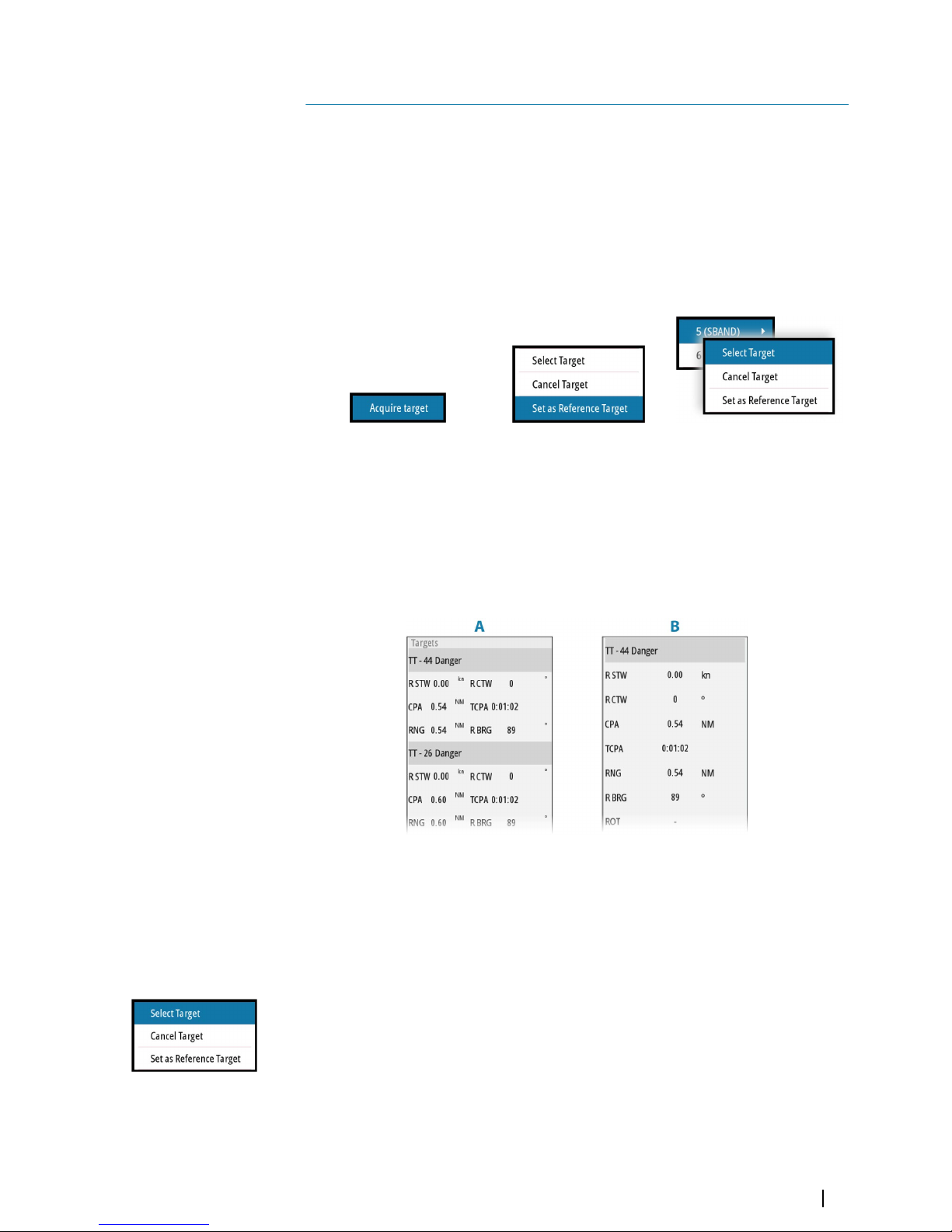
The items in the target menu depends on if a target is positioned at the cursor position, the
type of target, and the status of the target.
If more than one target is located at cursor position, the menu will show the reference
number for radar targets, and ship names for AIS targets.
No target at cursor position One target at cursor position Two radar targets at cursor position
Close the target menu by:
• Pressing the exit key
• Re-pressing the right mouse button
The target panel
The target panel can display basic information for up to four targets (A), or detailed
information about a selected target (B).
The following targets are included in the target panel:
• Tracked radar targets
• Activated AIS targets
• Dangerous targets
The targets listed are prioritized by the time they appear (the first appears on the top).
Selecting and de-selecting targets
AIS targets and tracked radar targets can be selected from the target menu. Only one target
can be selected at a time.
When you select a radar or an AIS target, the target symbol changes to the selected target
icon, and the target panel changes to show detailed information for the selected target
8
Targets | R5000 Operator manual
33
Page 34
Selected radar target Selected AIS target
To de-select a target and remove the detailed target information in the target panel:
• Select the deselect target option in the target menu
Ú
Note: Deselected target is placed first in the Target panel list.
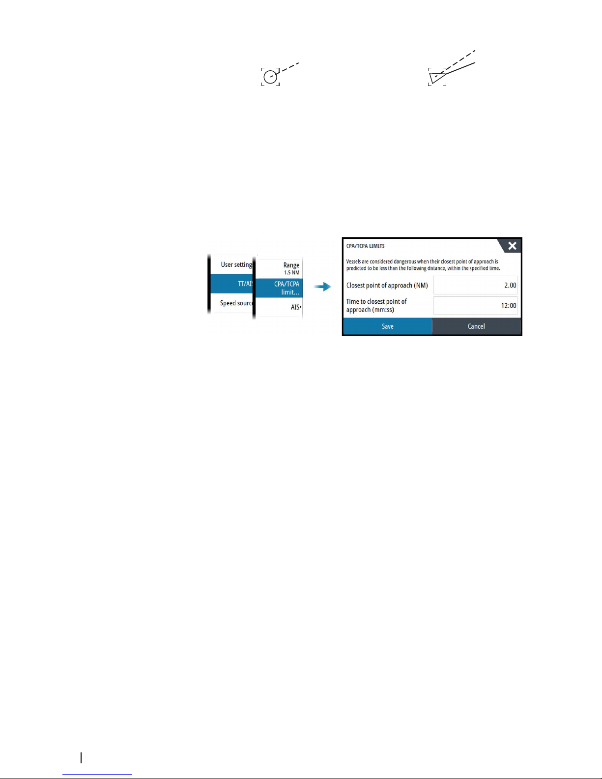
Defining dangerous vessels
You can use the CPA (Closest point of approach) and TCPA (Time to closest point of
approach) values to define when a target should be considered as dangerous. When a target
comes within the distance for CPA or within the time limit for TCPA, the symbol changes to
the dangerous target symbol.
Radar targets
Any radar echo within a preset range can be acquired and tracked. The system can track up
to a preset number of radar targets. For target range and number of targets, refer to "Technical
specifications" on page 78.
An alert is triggered if the number of tracked targets exceeds 95% of the maximum system
limitation and when maximum capacity is reached. Only the target closest to the own vessel
will be visualized.
You can manually acquire a radar target as described in the next section.
The guard zone option enables the system to automatically acquire targets. Refer to "Tracking
zones" on page 44.
Manually acquiring radar targets
When the cursor is active, you can immediately acquire a radar target at the cursor position
by:
• Pressing the enter key
• Pressing the left mouse button
You can also acquire a target from the target menu. Display the menu by:
• Pressing and holding the enter key
• Pressing the right cursor button
There might be a delay after having acquired a radar target before the system receives stable
target data:
• After 1 minute the symbol will show a trend vector, and speed and course of the trend will
be shown in the target panel
• After 3 minutes the symbol will become steady, and all the data fields of selected targets
will be available. The target symbol will change to the tracked radar target symbol.
The above time references represent worst case situations. In a stable situation the radar
target information is available immediately.
34
Targets | R5000 Operator manual
Page 35

Radar target symbols
The following symbols are used for radar targets in the system:
Symbol Description
Tracked radar target with velocity vector
Selected radar target, indicated with a square (dotted line)
around the target symbol
Dangerous radar target, indicated with bold line and with red
color. The symbol flashes until the target alarm is acknowledged by
the operator. It remains red until the system no longer defines it as a
dangerous target
Lost radar target, indicated with crossed lines centered on the
target symbol. The symbol is located at the last received position
from the target
R
Reference target
18
Radar target with past position and velocity vector
Radar target in acquisition state, indicated as a broken circle
centered at the position of target acquisition
Associated target - using radar data
Display settings for radar targets
You select how the radar targets are displayed on the radar image in the trails and past
position menu.
The settings are indicated in the indicators panel.
Trails and past position presentation mode
Trails and past position indicators can be displayed as either true or relative to own ship.
Trails and past position indicators are available in both sea and ground stabilization modes.
See "Selecting speed source" on page 20.
Target trails
A target trail indicates the target movement by leaving an afterglow, gradually reducing the
intensity over time.
Target trails show where a target used to be, and the function is useful for quickly assessing
the movement of targets relative to your own vessel.
Targets | R5000 Operator manual
35
Page 36

You can set the length of the trails. The length represents the time it takes for the trails to
fade out.
The clear trails option clears target trails from your radar panel temporarily. The trails start to
build up again unless you switch the function off.
Showing a target's past position
• Past positions: used to visualize the previous positions of a tracked target or an activated
AIS target
• Time: defines the length of time for which each target's past positions should be displayed
on the PPI
• Interval: defines the distance between each past position indicator
Warning: Trails build-up starts when exiting from the standby condition.
Trails or past position length will be reached only after the selected time
duration.
Possible target tracking errors
Some factors can generate tracking errors or make the radar image difficult to read, and
therefore reduce target detection capability:
• Sea, rain, snow and low clouds returns
• Radar Interference
• Sidelobe echoes
• Blind sectors
• Low signal to noise ratio and signal to clutter ratio
Warning: The speed and course of a radar target are obtained by
consecutive measurements of the echo position. The data is then filtered to
reach the required precision. This means, that every abrupt change of speed
and direction will be recognized with a certain delay to reach absolute
certainty that the target is moving in a different way. The confirmation delay
is about five scans and after that some additional time is needed to reach
the same data precision as from before the maneuver.
Sea, rain, snow and low clouds returns
Radar echoes in sea, rain or weather clutter areas may be masked by the clutter. The effects
of such errors appear as continuous big changes of the target course and speed vectors.
Sometimes the symbol of a target that has been acquired at high speed can slip away from
the real target position after a certain time, and this might generate the lost target alarm.
These errors can be avoided or at least minimized by proper manual adjustments of sea and
rain controls, or by selecting the automatic control option. For more details, see "Adjusting the
radar image" on page 27.
Radar interference
Other radars operating in the same frequency band can generate interference. Normally this
is seen on the radar screen as a series of spirals. When the interference falls on the tracked
target, it can cause a deformation of the size of the echo, and consequently a small error in
the target's course and speed values.
Adjustment option is available in the advanced menu. See "Rejecting radar interference" on page
55.
Second trace echo
A second trace echo is an echo received from a distant target, received after the following
pulse has been transmitted.
Second trace echoes are present only under abnormal atmospheric conditions, or in
condition of super-refraction.
36
Targets | R5000 Operator manual
Page 37

These echoes will be displayed at their correct bearing, but at a wrong range.
Second trace echoes can be recognized by their irregular shape. Since the period between
two subsequent transmitted pulses is subject to small variations, the second trace echo
appears undefined and hazy.
Second trace echoes are automatically suppressed by the radar when the interference
rejection is turned on. Refer "Rejecting radar interference" on page 55.
Sidelobe echoes
Radar antennas have a radiation pattern consisting of a main lobe and several very small
sidelobes. Most of the energy transmitted by the radar is radiated and received back on the
main lobe, and a very small part on the sidelobes. This has no effect in case of distant or small
targets, but the returns from a large target at short range (less than 3 NM) can generate, on
both sides of the main echo and at the same range, arcs or series of small echoes. These
effects, when they are an extension of the main echo, can cause momentary errors for the
tracking, and course and speed values given by the tracking can become unstable.
The problem can usually be eliminated or strongly reduced by an accurate adjustment of the
Sea control. Refer "Sea anti-clutter" on page 27.
Blind sectors
Funnels, masts or other obstructions (when located near the radar antenna) may cause blind
or shadow sectors, where the target visibility may be completely lost or strongly reduced.
Targets remaining in these sectors for a long time (more than 10 antenna revolutions) will be
considered lost, and the lost target alert will be triggered.
Low signal to noise ratio and signal to clutter ratio
In situations where the signal to noise or the signal to clutter ratio of the radar echoes is low
(small vessels in heavy sea or rain clutter, or big vessels close to the radar horizon), target
detection is poor and the tracking will not detect the target at each antenna revolution. This
will cause errors in the tracking, and it can range from missed information and up to
complete loss of the target when it is missed for 10 consecutive antenna revolutions.
Radar SART
A SART (Search And Rescue Transponder) is used for emergencies. These devices may be
either a radar-SART, or a GPS-based AIS-SART.
The radar-SART is used to locate a survival craft or distressed vessel by creating a series of
dots on the radar PPI. The range for detection of a radar-SART is normally about 8 NM, and its
signal may be triggered by any HD or X-Band radar.
Since the radar-SART is very near, side lobes from the radar antenna may show the responses
as a series of concentric arcs or rings. This effect can be removed by using the Sea anti-clutter
control. It is useful to observe the side lobes as they might be easier to detect in clutter
conditions, and they will confirm that the radar-SART is very close to own ship.
A
B
C
D
Radar-SART far from own vessel (range: 24 NM)
B
A
D
Radar-SART close to own vessel (range: 3 NM)
A Position of SART
B Echo from SART
Targets | R5000 Operator manual
37
Page 38

C Radar antenna beamwidth
D Own ship position
Recommended settings for radar-SART detection
To best detect a radar-SART signal, adjust the settings as follows:
• Set the range scale between 6 and 24 NM
-
The spacing between responses is too small to be distinguished at higher scales (0.64
NM)
- The length of the radar-SART response (12 dots) may be extended to 9.5 NM beyond
the position of the radar-SART, and it is necessary to see more than one response dot
to distinguish the radar-SART from other responses
• Set the sea clutter control to manual mode and adjust it to minimum
-
A high value could remove the SART response
Ú
Note: With a minimum value for SEA anti-clutter, ships inside the clutter range may not
be visible to the radar.
If the sea clutter is strong when the SEA anti-clutter control is set to minimum, the first
few dots of the radar-SART response might not be detectable. In such conditions, the
position of the radar-SART may be estimated by using the EBL/VRM off center function
and measure 9.5 nautical miles from the farthest dot back towards own ship.
• Set the rain anti-clutter control to manual mode, and adjust as required to avoid rain
clutter
- The setting does not affect the radar-SART detection
• Set the gain control to manual mode, and adjust it to see some noise dots in the
background
- Normal gain setting for long range detection can usually be used (around 80% of max
range)
• Turn OFF target boost. See
"Target boost" on page 55
- The shape and dimension of the radar-SART dots could be affected by this setting.
Warning: The operator should take care when using the radar with these
settings. The detuned radar will not be able to see and track targets as well
as it will when it is tuned, and the anti-collision functions may no longer be
working. The tuning should be returned to normal as soon as possible.
Racons
A racon (radar beacon) is a radar transponder commonly used to mark maritime navigational
hazards.
A racon responds to a received radar pulse by transmitting an identifiable mark back to the
radar. The displayed response has a length on the radar display corresponding to a few
nautical miles, encoded as a Morse character beginning with a dash for identification. The
inherent delay in the racon causes the displayed response to appear behind the echo from
the structure on which the racon is mounted (A).
A
38
Targets | R5000 Operator manual
Page 39

Racons and their identifying marks are normally indicated on marine charts. Their purpose
can change with the country they are used in. Generally they are used to:
• Identify aids to navigation, both seaborne (buoys) and land-based (lighthouses)
• Identify landfall or positions on inconspicuous coastlines
• Indicate navigable spans under bridges
• Identify offshore oil platforms and similar structures
• Identify and warn of environmentally-sensitive areas (such as coral reefs)
In some countries they are also used to:
• Mark new and uncharted hazards (these should use the Morse identifier “D”)
• Identify center and turning points
• Leading line racons
Racons installed on buoys are usually active for 20 seconds, and then off for the next 20
seconds.
Recommended settings for racon detection
The racon response could be degraded by rain and sea anti-clutter control, and by
interference suppression. Turning off of the above mentioned settings should improve the
racon visibility on the PPI. The detection range of a racon may also be reduced if the radar
receiver is not tuned.
AIS targets
If a compatible AIS receiver is connected to the radar system, AIS targets can be displayed
and tracked.
The system can display and activate a preset number of AIS targets. Refer details in "Technical
specifications" on page 78. An alert is triggered if the number of AIS targets exceeds 95% of the
maximum system limitation and when the maximum capacity is reached. When the total AIS
capacity is reached, additional AIS targets will be visualized following a range based priority
logic. Only the target closest to the own vessel will be visualized.
The AIS function is available when:
• AIS data is available through the serial line
• Gyro compass heading is available. If gyro heading is lost the AIS function is automatically
switched OFF
• EPFS valid position is available
By default, all AIS targets are shown as sleeping targets if the AIS function is turned ON. You
can manually activate a sleeping target, or you can set up the system to automatically
activate sleeping targets as described in the next sections.
AIS targets can be filtered as described in "AIS target filters" on page 41.
Activating AIS targets
AIS targets are initially presented in sleeping status (A). A sleeping target does not show
vectors and heading lines, but only a small icon pointing in the direction of the target's
heading.
You can switch a sleeping target to an activated target (B). An activated AIS target shows a
larger icon, and it has an associated vector, heading line and a turning indicator if available.
Only activated AIS targets are listed in the target panel.
Activated AIS targets are always processed against CPA/TCPA limits, and are defined as
dangerous targets if the CPA/TCPA limits are exceeded.
Targets | R5000 Operator manual
39
Page 40

Manually activating an AIS target
When the cursor is active, you can immediately activate an AIS target at cursor position by:
• Pressing the enter key
• Pressing the left mouse button
You can also activate an AIS target from the target menu, displayed by:
• Pressing and holding the enter key
• Pressing the right cursor button
Automatically activating AIS targets
You can enable the system to automatically switch a sleeping target to an activated target
when the CPA or TCPA is lower than the set minimum safe value. In this situation the AIS
target is automatically defined as a dangerous target.
AIS vessel ID
Activated AIS targets are shown with the vessel ID.
AIS target symbols
The following icons are used for AIS targets in the system:
Symbol Description
Sleeping AIS target, aligned with received heading information or
with COG information if heading is not available
AIS target with heading line and SOG/COG (dashed line), and with
indicated turn direction
AIS target with true scaled outlines
AIS target with past track
Selected AIS target, indicated with a square (dashed line) around
the target symbol
40
Targets | R5000 Operator manual
Page 41
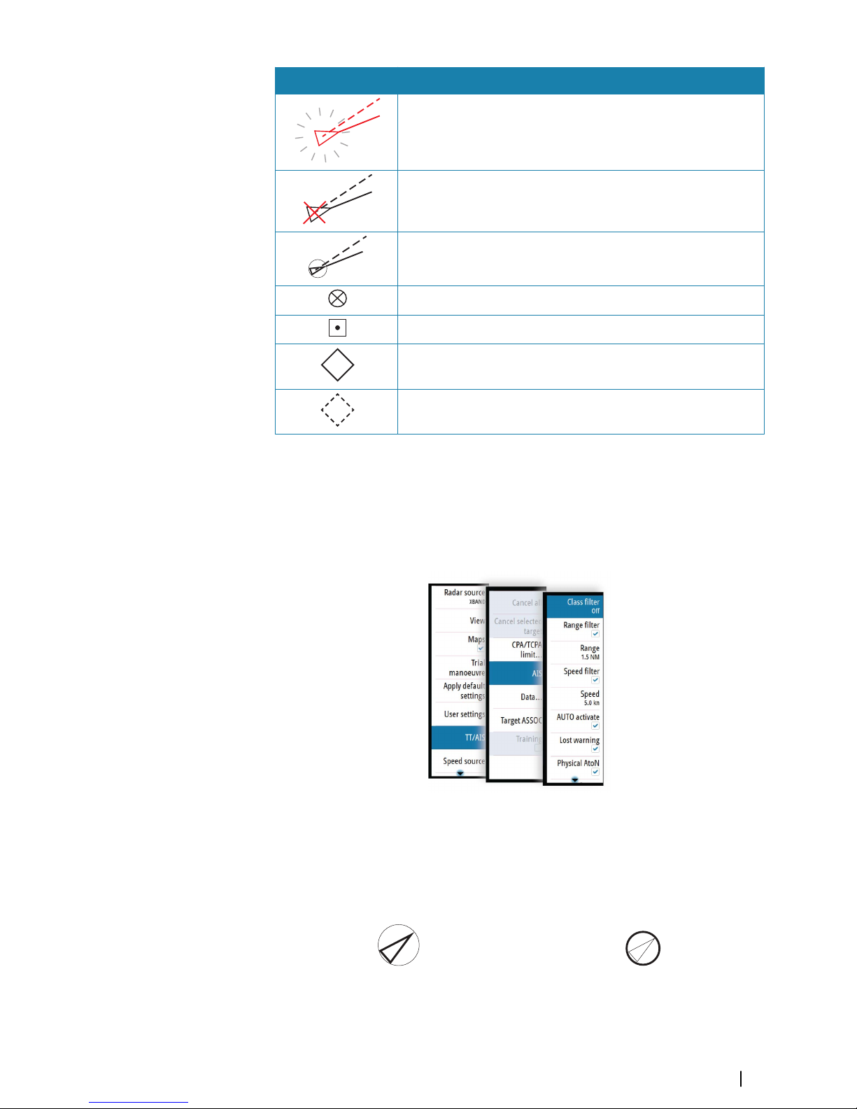
Symbol Description
Dangerous AIS target indicated with bold line and with red color.
The symbol flashes until the target alarm is acknowledged by the
operator
Lost AIS target, indicated with crossed lines centered on the target
symbol. The symbol is located at the last received position from the
target
Associated target - using AIS data
AIS SART (AIS Search And Rescue Transmitter)
AIS Base station
Real AtoN (Aids To Navigation)
+
Virtual AtoN
For a complete list of AIS and AtoN symbols, refer to "Target symbols" on page 70.
Ú
Note: A symbol is drawn with a dashed line if the collision avoidance cannot be
calculated.
AIS target filters
You can select to filter the icons based on AIS class, range and target speed.
AIS and radar target association
When an echo with its AIS symbol on top is being acquired for tracking, the system can
detect that the two symbols represent the same target with the target association function.
When the function is activated, the radar target and the AIS target are associated. You select
whether to use source data from the AIS target or from the tracked radar target.
Associated targets - using AIS data Associated targets - using radar data
This function is useful for reducing the number of AIS symbols and radar targets on the PPI.
Too many targets could clutter the screen and result in dangerous situations. The function
Targets | R5000 Operator manual
41
Page 42
also compensates for a possible failure in one of the two targets, e.g. if the radar tracked
target is positioned behind an island, the system keeps tracking and visualizing the AIS
target.
Ú
Note: The tracked radar target continues to be analyzed by the system when the target
association is active.
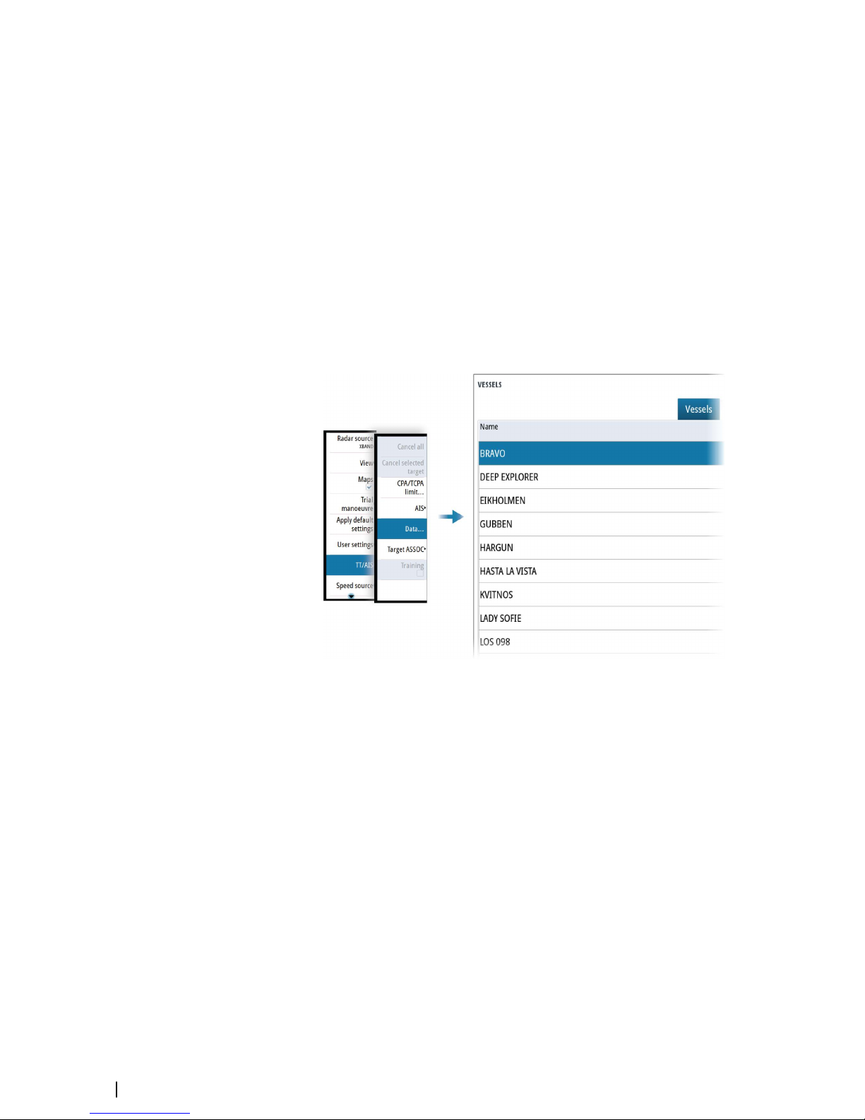
Displaying target information
The vessels dialog
The vessels dialog displays a list of all AIS and MARPA targets.
By default, the dialog lists targets, arranged by distance to own vessel. You can select to
change the sort order, and to display only a selected target type.
The vessels dialog also lists received AIS messages.
To display the vessels dialog:
• select the data option in the menu
• press and hold the AIS key
AIS vessel details
Detailed information about an AIS target is available from the AIS vessels details dialog.
To display the dialog:
• select the AIS additional information option in the target menu
• select an AIS target in the vessels dialog
42
Targets | R5000 Operator manual
Page 43

Training simulator
The training function is used to train the operator on manual radar target acquisition, on
target selection and on the tracking procedures.
The function is activated from the menu.
When started the system replays a pre-loaded file, simulating a target with constant speed
and course approaching own vessel. The training target's speed is as per the pre-loaded file,
and it cannot be altered by the user. The CPA and TCPA depends on the simulated target's
speed and own vessel's speed.
A flashing S is shown on the lower part of the screen as long as the function is active to warn
that training simulation is running.
You can perform all tracking operations on the simulated target.
The CPA and TCPA of the training target is automatically tested by the system. Alerts are
raised in case of a malfunctioning of the tracking software:
• Training Tgt CPA Out of Range: if the difference between theoretical and target displayed
CPA is greater than 0.5NM
• Training Tgt TCPA Out of Range: if the difference between theoretical and target displayed
CPA is greater than 30sec
The radar will return to default operation as soon as the training option is turned off from the
menu.
Targets | R5000 Operator manual
43
Page 44
Navigation tools
Tracking zones
The tracking zone function allows for automatic acquisition of radar and AIS targets when
they enter a user defined zone ahead or around your vessel.
Two tracking zones can be defined, each with individual settings.
When a target enters a zone, it will automatically be considered as safe or dangerous based
on the CPA/TCPA settings.
Two types of tracking zones are available.
Guard zone
When a target enters a guard zone the following happens:
• radar targets are acquired and AIS targets activated
• warning about new target and warning about target being in zone are activated
• the target icon turns red and flashing
When the warning about new target is acknowledged, the icon stops flashing. The icon
remains red until the target leaves the guard zone.
The color of the border line of a guard zone is defined by the user.
Auto acquisition zone
When a target enters an auto acquisition zone the following happens:
• radar targets are acquired and AIS targets activated
• warning about new target is activated
• the target icon turns red and flashing
When the warning is acknowledged, the target change to basic target icon and color
depending on its status (save or dangerous).
The border line of an auto acquisition zone is white.
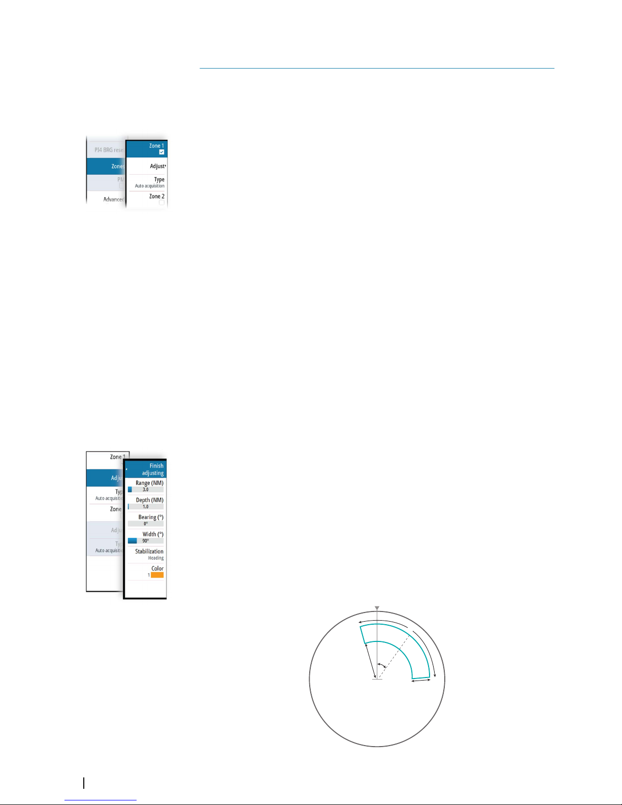
Defining a tracking zone
1 Turn ON the tracking zone you want to define
• The tracking zone lines are displayed on the radar PPI
2 Select the adjust option
• The tracking zone lines turns to dashed lines to indicate that you are in edit
mode
3 Define the guard zone options:
A: Range, relative to vessel center
B: Depth
C: Bearing, relative to vessel heading or to North
D: Width
A
B
C
D
9
44
Navigation tools | R5000 Operator manual
Page 45
4 Select the type for the zone
Ú
Note: The line color is only applicable when the type is set to guard zone. The line color
is always white if the type is set to auto acquisition.
5 Save the changes by selecting the finish adjusting option in the menu
Ú
Note: If you exit the menu by pressing the exit key, the zone remains in edit mode. The
lines remain with dashed lines, and the zone is not active.
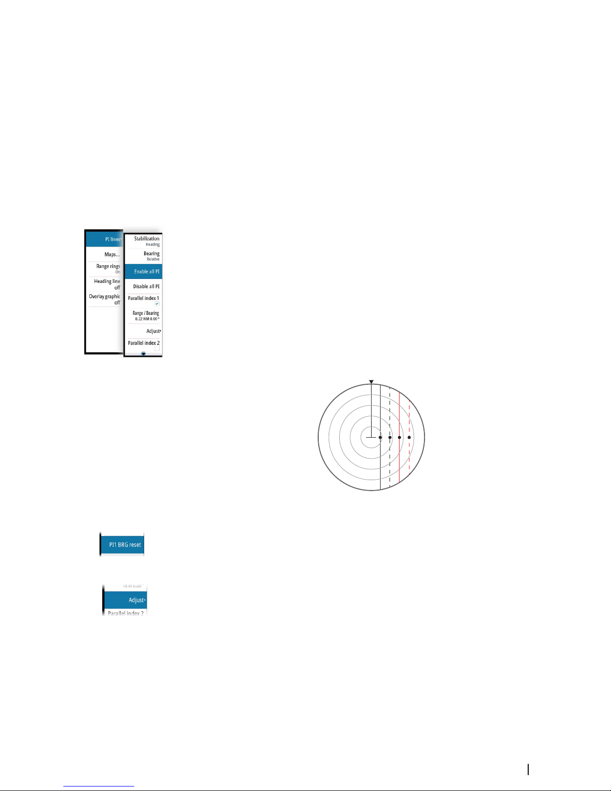
Parallel index lines
Parallel Index (PI) lines are used to visualize the distance to own vessel, other vessels or to
land objects. Two index lines can be used to indicate a corridor - typically used to visualize an
area you want to maneuver within.
The PI lines can be defined with north or heading stabilization, and with true or relative
bearing.
• North stabilization: the line direction is maintained with respect to north
• Heading stabilization: the line rotates with the vessel heading
• True bearings: the parallel index bearing is measured from the geographical north
• Relative bearings: the parallel index bearing is measured from the heading line
You can define four PI lines in the system, and they are identified with different color and
style:
• PI1: Grey solid line
• PI2: Grey dashed line
• PI3: Orange solid line
• PI4: Orange dashed line
1 2 3 4
You can turn each PI line on and off individually, and the position, bearing and truncating
can be set for each line.
Each PI line can be reset to be parallel to own ship's heading from the main menu.
Adjusting a PI line
Each PI line's range and bearing are shown in PI lines submenu.
You can adjust the line's settings from the selected line's Adjust menu option. The options
described in the next sections are available.
Adjusting range and bearing
1. Select the range or bearing menu options
-
The slider bar is displayed
2. Turn the rotary knob or use the up/down arrow keys to increase or decrease the slider bar
value
- The change is immediately committed and shown on the image
3. Press the exit key or the right arrow key to leave the edit mode
Ú
Note: Max range for a bearing line is 12 NM.
Navigation tools | R5000 Operator manual
45
Page 46

Truncating a PI line
You can use the truncate menu option to extend or reduce an existing PI line. The end points
of the line (A and B) are adjusted individually.
1. Select the truncate A or B option in the menu.
- The slider bar is displayed
2. Turn the rotary knob to extend or reduce the line
3. Press the exit key to confirm the selection
2
Function activated
2
End point adjusted
2
Line truncated
A line remains truncated until the restore length option is selected from the menu.
PI line alignment
A PI line can be parallel to port or starboard of the heading line, or to the port or starboard
side of an EBL.
• If the stabilization is set to heading, the PI line rotates as the vessel heading change
• Parallel to EBL is a way to quickly set the bearing of a PI line parallel to the EBL in use. The
line does not rotate if the EBL is changed later.
EBL/VRM markers
The EBL/VRM markers are a basic tool for collision avoidance. They are used to mark any fixed
or moving radar target, and to measure distances between two objects.
The reference point of an EBL/VRM marker is by default positioned at the center of the vessel.
It is possible to offset the reference point to any selected position on the radar image to
measure the distance between two objects on the PPI, or to fix the marker to a target.
Two different EBL/VRMs can be placed on the radar image. They are identified as dashed
rings/lines with different colors to discriminate them from each other and from the fixed
range rings:
• EBM/VRM1 is cyan
• EBL/VRM2 is blue
The EBL presentation can be defined with true or relative presentation:
A
B
2
46
Navigation tools | R5000 Operator manual
Page 47

• True motion: the reference is geographic (e.g. a coastal line or current own vessel position)
• Relative motion: the EBL follows a moving reference (own vessel or a moving target)
The marker's line width indicates whether the marker is in edit mode (bold lines) or at a fixed
position (thin lines).
EBL/VRM1 OFF,
function not active
EBL/VRM1 ON,
EBL in edit mode
EBL/VRM1 ON,
VRM in edit mode
The EBL/VRM pop-up
The content of the pop-up depends on status of the active EBL/VRM. The example shows the
pop-up when the active EBL/VRM is offset.
The adjustable parameter is indicated with blue text in the softkey.
From the pop-up you can:
• switch between active EBL/VRM 1 and EBL/VRM 2 marker
• turn ON/OFF displaying of the active marker
• switch between adjusting EBL and VRM for the active marker. You can also switch
between adjustable parameter by pressing the rotary knob
• set EBL presentation (True or Relative)
• set offset for active marker
• reset an offset marker to vessel position
• select whether the EBL/VRM should be locked to own vessel or to a geographical position
Turning the EBL/VRM marker on and off
At system start-up, both EBL/VRM markers are turned off.
• Turn ON EBL/VRM 1 by pressing the EBL/VRM key once
• Switch between EBL/VRM 1 and EBL/VRM 2 from the function's pop-up
• Turn OFF an EBL/VRM from the function's pop-up
Adjusting the EBL/VRM marker
The text in the EBL/VRM short-cut button and the EBL/VRM marker's line width indicate
which item that is in edit mode.
EBL/VRM2 ON,
function not in edit mode
EBL/VRM1 and 2 ON,
EBL1 in edit mode
EBL/VRM1 and 2 ON,
VRM1 in edit mode
Navigation tools | R5000 Operator manual
47
Page 48
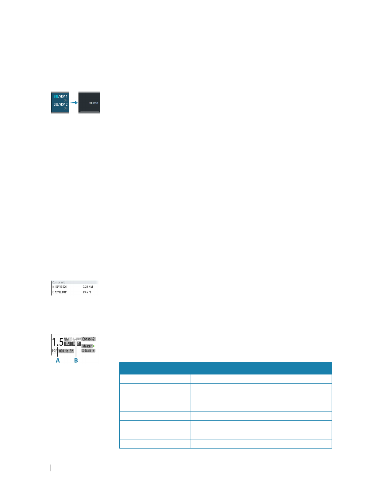
When an EBL/VRM marker is in edit mode, the following options are available for adjusting
the marker:
• Use the arrow keys or mouse to move the EBL/VRM intersection
• Turn the rotary knob or left mouse key/scroll wheel to adjust the adjustable parameter
(bold line and blue text in softkey)
• Press the rotary knob or mouse scroll wheel to switch between adjusting EBL and VRM
Offsetting EBL/VRM markers
1. Press the EBL/VRM key twice to display the pop-up
2. Select the set offset option
- The pop-up closes, and the cursor is positioned in the EBL/VRM center
3. Use the arrow keys to move the EBL/VRM center, then select one of the following options:
- Press the enter key to fix the marker to the selected position, then use the arrow keys
to move the EBL/VRM intersection
-
Turn the rotary knob to adjust the EBL
- Press the rotary knob to toggle between EBL and VRM, then turn the rotary knob or use
the arrow keys to adjust the item that is editable
You remove the EBL/VRM marker from the radar image by pressing the exit key.
Measuring range and bearing
Different options are available for measuring the position, speed, course, distance and
bearing of radar echoes.
• Cursor position
• Range rings and bearing scale
• EBL (Electronic Bearing Lines) and VRM (Variable Range Markers)
It is important to minimize the range to obtain the best precision for the measurement. In
most cases you can use a higher range if you position the PPI in one of the off-center modes.
Refer to "Offsetting the PPI center" on page 31.
Ú
Note: Every measurement made with cursor or EBL/VRM is always referred to the
Consistent Common Reference Point (CCRP).
Using the cursor
When you position the cursor over a target, the cursor information area will show range and
bearing from the vessel to the cursor position.
This measuring option gives a fast and precise measurement of distance to a target.
Range rings and bearing scale
Range rings and bearing scale are used to measure distance when a fast measurement is
required. This measuring option only gives an approximate distance and speed of a target.
The range scale (A) and the distance between two adjacent range rings (B) are shown in the
System Information area on the radar image.
The range scales, the related distance between the range rings and number of rings are:
Range (NM) Range rings interval (NM) Number of range rings
1/8 (200m) 1/40 (100m) 1
1/4 1/20 4
1/2 1/10 4
3/4 1/4 2
1.5 1/4 5
3 1/2 5
6 1 5
12 2 5
48
Navigation tools | R5000 Operator manual
Page 49

Range (NM) Range rings interval (NM) Number of range rings
24 4 5
36 6 5
48 8 5
64 16 3
72 12 5
Measuring by using EBL/VRM markers
The Electronic Bearing Line (EBL) and Variable Range Marker (VRM) allows quick
measurements of range and bearing from own vessel to a target, or between two targets on
the PPI. Bearing and range are shown in the Markers panel (A).
Measuring distance from own vessel
1. Press the EBL/VRM key to turn the selected EBL/VRM marker on
2. Repress the EBL/VRM key to display the pop-up if you need to:
-
Select the EBL presentation (True or Relative)
- Reposition the marker to vessel position (if the center of the selected EBL/VRM is offset)
3. Use the arrow keys or turn the rotary knob to position the EBL/VRM on the second
measuring point
Measuring distance between two objects
1. Press the EBL/VRM key twice
-
The selected EBL/VRM marker is turned on and the pop-up displayed
2. Select the EBL presentation (true or relative)
3. Select the set offset option
4. Use the arrow keys to reposition the EBL/VRM marker's center on the object from where
you want to measure the distance
5. Press the enter key to confirm the position
- The cursor moves from the marker's center to the EBL/VRM intersection
6. Use the arrow keys or turn the rotary knob to move the EBL/VRM to the second
measuring point
- Range and bearing from the EBL/VRM marker's center to cursor position is now
displayed in the Markers panel
You can reset the EBL/VRM marker's center to vessel position by selecting the reset offset
option in the EBL/VRM pop-up.
Navigation tools | R5000 Operator manual
49
Page 50

Maps
Maps are graphical navigation tools, composed of lines and symbols that can be added to
the radar image. Maps are used to help the operator to increase the definition of the coast,
restricted or dangerous areas.
For maximum number of maps, symbols and segments, refer to "Technical specifications" on page
78.
Ú
Note: The maps option must be enabled to be able to work with maps.
The maps dialog
The maps dialog lists all maps available in the unit's temporary memory and in the nonvolatile memory.
From the maps dialog you can:
• Import stored map files from the unit's internal file system or from an SD card (A)
• Select which maps that are displayed (B)
• Set a map's reference (C)
• Display the maps pop-up from where you can create new maps, edit, save, export and
delete a map (D / E)
Map references
The system includes the follow map types:
• Relative maps, which follows the position and equals the heading of own ship. All relative
map coordinates are stored as distances from own ship
• Geographic maps. The coordinates for this type of maps are stored as geographic
positions, and its elements are always drawn in the same absolute position.
When a map is saved the system automatically calculates both relative and the geographic
details for all map items. When you switch reference the change is immediately committed
without having to save the map.
Ú
Note: Relative maps cannot be created or imported if log or gyro is unavailable or failing.
Ú
Note: Geographic maps cannot be created or imported if EPFS (Electronic Position Fixing
System) or Gyro is unavailable or failing. A geographic map cannot be displayed if the
ship is too far from the area of the map.
10
50
Maps | R5000 Operator manual
Page 51

Map colors and symbols
Lines and map symbols can be presented in various colors.
The following map symbols are available:
Sym
bol
Description
Sym
bol
Description
Sym
bol
Description
Buoy North Area Caution Arrow W
Buoy South
D
Area Depth Arrow NW
Buoy East Area Empty Sign Call
Buoy West
?
Area Ufo Sign Reminder
Buoy Lateral Port Arrow N Nato 1
Buoy Lateral Stbd Arrow NE Nato 2
Buoy Special Arrow E Nato 3
Buoy Danger Arrow SE Nato 4
Buoy Safe Arrow S Nato 5
?
Buoy Unknown Arrow SW Nato 6
Creating a new map
When the create map option is selected, a new map is immediately saved to the unit's
temporary memory.
The map name is defined by the system, and the visibility is set to ON.
Ú
Note: The new map has at this stage no content.
• Select the map name to display the keyboard if you want to give the map a unique name
• Set the map reference
• Select the menu option to enter map details. See "Modifying a map" on page 52.
Maps | R5000 Operator manual
51
Page 52
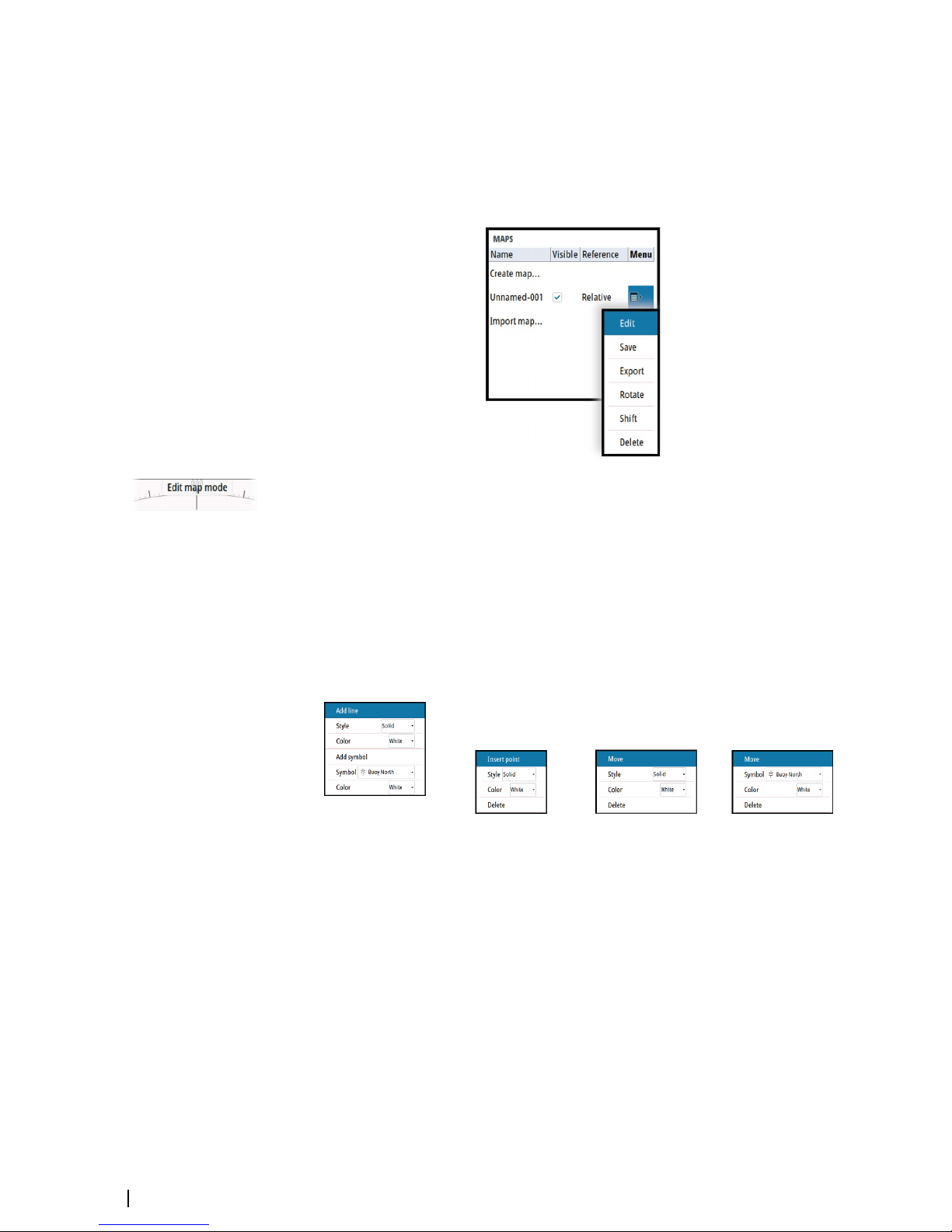
Saving a map
New maps and edited maps are by default saved to the unit's temporary memory. The maps
must be saved to be available in the unit after a restart.
Modifying a map
Any details for a map are added or edited from the maps pop-up menu.
When an edit option is selected in the pop-up menu, the system turns into edit map mode.
This is indicated on the PPI.
To exit edit map mode:
• Press the exit key
Ú
Note: When you exit edit mode the changes are automatically saved to the temporary
memory only. The maps must be saved to be available in the unit after a restart.
Edit map details
Map details are added or edited from the edit map menu. The content of the edit map menu
depends on where the cursor is positioned:
No map details at cursor
position Map line at cursor position Vertex at cursor position Symbol at cursor position
1. Position the cursor where you want to add or edit a map detail
2. Press the enter key or the right mouse key to display the map edit menu, then select the
edit option
3. Continue positioning the cursor and selecting the edit option until all changes are done
4. Press the exit key to leave the edit mode
52
Maps | R5000 Operator manual
Page 53

Rotating a map
When the rotate option is selected, the cursor is positioned in the center of the PPI.
• Use the arrow keys to move the cursor and to rotate the map around the vessel's position
• Press the exit key to leave edit mode
Shifting a map position
When the shift option is selected, the cursor is positioned in the center of the PPI, and the
map is anchored to the cursor.
• Use the arrow keys to move the cursor and to shift the map position
• Press the exit key to leave edit mode
Exporting maps
Maps listed in the maps dialog can be exported individually and used on other compatible
radar units.
Saved maps can also be copied from internal memory to a memory card from the files
management system.
Importing maps
Compatible maps created on other units can be imported to the system. Imported maps are
added to the units' non-volatile memory, and the maps are added to the list of loaded maps.
Maps | R5000 Operator manual
53
Page 54

Customizing radar control settings
You can save several control settings in the system. The function is used for defining various
conditions and user preferences.
For recalling default control settings, refer to "Applying default control settings" on page 23.
Customizing radar control settings table
The following functions are included when you save a user setting:
Function Default setting
Band X-band
Gain, Rain and Sea Automatic
Tuning Automatic
Range 6 NM
Fixed range rings Off
VRMs One VRM on at 0.25 NM
EBLs Off or last settings
Parallel index lines Off or last settings
Display mode of PPI True motion, north up
Stabilization Sea/Ground Ground (SOG, COG)
Off-centering Look ahead
Target trails On, 6 minutes (same as vector)
Past position Off
Radar target tracking Continued
Vector mode Relative
Vector time 6 minutes
Graphical AIS reported target display On
Radar and AIS target function Association On
Operational alarms (except collision
warnings)
Off
Collision warning On (limits CPS 2 NM, TCPA 12 minutes)
Display of maps, navigation lines and routes Last settings
11
54
Customizing radar control settings | R5000 Operator manual
Page 55
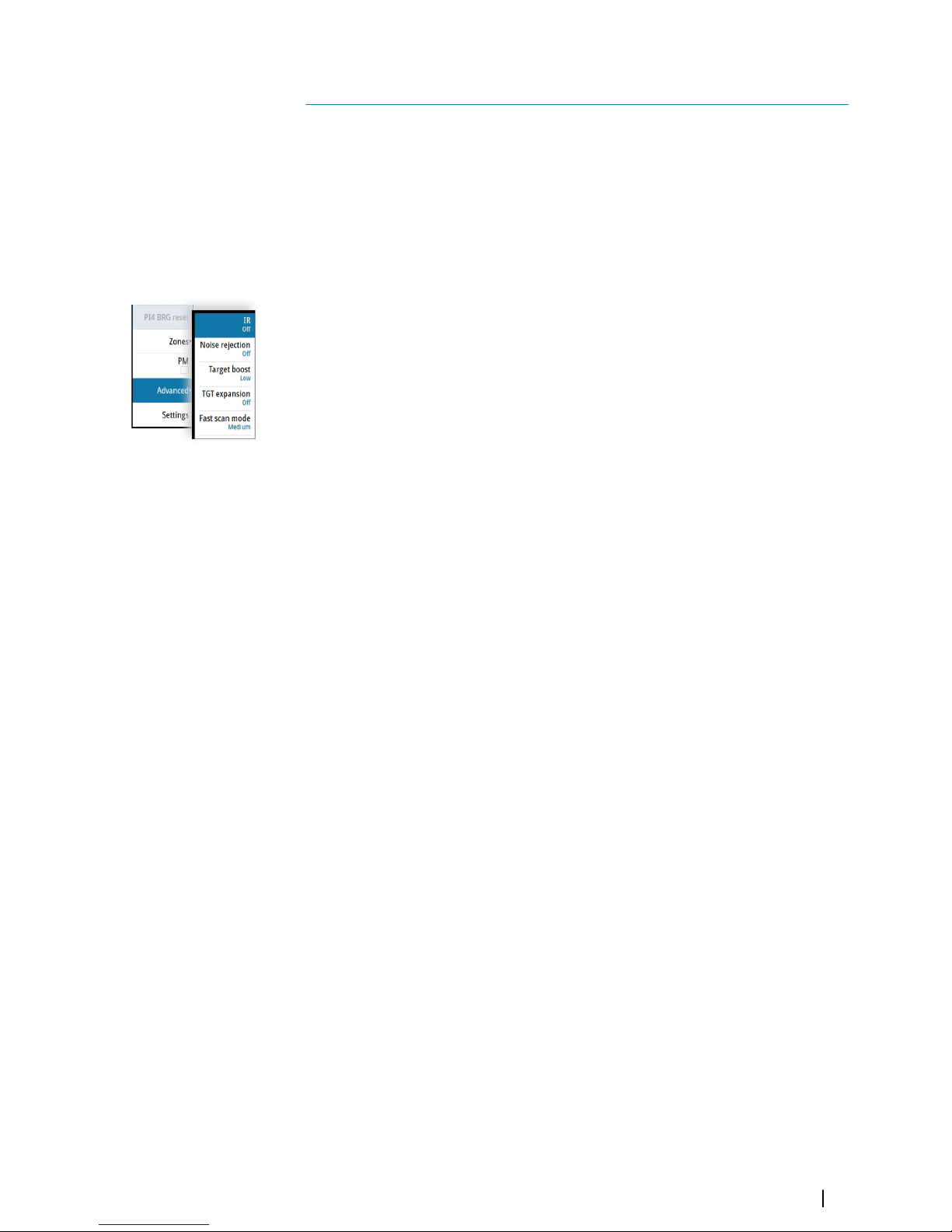
Advanced options
Rejecting radar interference
The IR (Interference rejection) is used to eliminate second trace echoes from far distance
targets, and the interference from radar units operating in the same frequency band.
When the IR is ON, transceiver pulse staggering is enabled. When enabled, the transceiver
PRF is changed slightly for each sweep. By doing this, spiral interferences and second trace
echoes are split in range from sweep to sweep. The IR processing clears all the echoes found
at the same range if they are not present in each sweep.
The IR must be chosen according to the environment around own ship:
• IR off when the maximum signal from the receiver is needed
• IR on when the interference or second trace echoes disturb the radar image
To avoid missing weak targets, the interference rejection should be set to OFF when no
interference exists.
Noise rejection
The Noise Rejection control sets the amount of noise filtering applied by the radar. Target
sensitivity is increased at longer ranges when this control is set to Low or High, but does
cause some loss of target discrimination.
Target boost
The target boost control increases pulse length, reduces radar bandwidth to make targets
appear larger in range, and increase radar sensitivity.
TGT expansion
Target expansion increases the length of targets in range, making them easier to see.
Fast scan
Change the speed of the radar antenna rotation from 20 RPM in standard mode to 40 RPM in
fast scan mode. This option gives faster target updates.
Ú
Note: The fast scan option is not available for 12 feet X-band antennas and for HSC radar
sensors.
12
Advanced options | R5000 Operator manual
55
Page 56

Trial maneuver
The trial maneuver option is used to avoid dangerous situations when planning a maneuver
in heavy traffic areas.
The trial maneuver presents a graphical view of a simulated maneuver, including the
predicted position of own vessel relative to tracked targets and AIS targets.
Ú
Note: The best trial maneuver information is available when running the radar in Relative
motion and with speed source stabilization set to Sea mode. Refer to "Relative motion" on
page 30, and to "Selecting speed source" on page 20.
Trial maneuver symbology
When the trial maneuver is started, the trial symbol (A) and the countdown time (B) is added
to the radar image. A Trial maneuver panel (C) is added to the radar panel.
The target indication is according to the radar view settings and speed stabilization mode.
The targets are indicated with actual position. Select a target to see its predicted position (E).
The estimated motion line (EML) is then added between the two target positions.
If you select a target's predicted position, the target name and the predicted position are
added to the panel (D).
Indication of a dangerous maneuver
The following indications are used to indicate that a target's position is a dangerous at the
end of the trial maneuver:
• flashing red target symbol
• yellow color in the trial maneuver panel
• a relevant alarm
13
56
Trial maneuver | R5000 Operator manual
Page 57
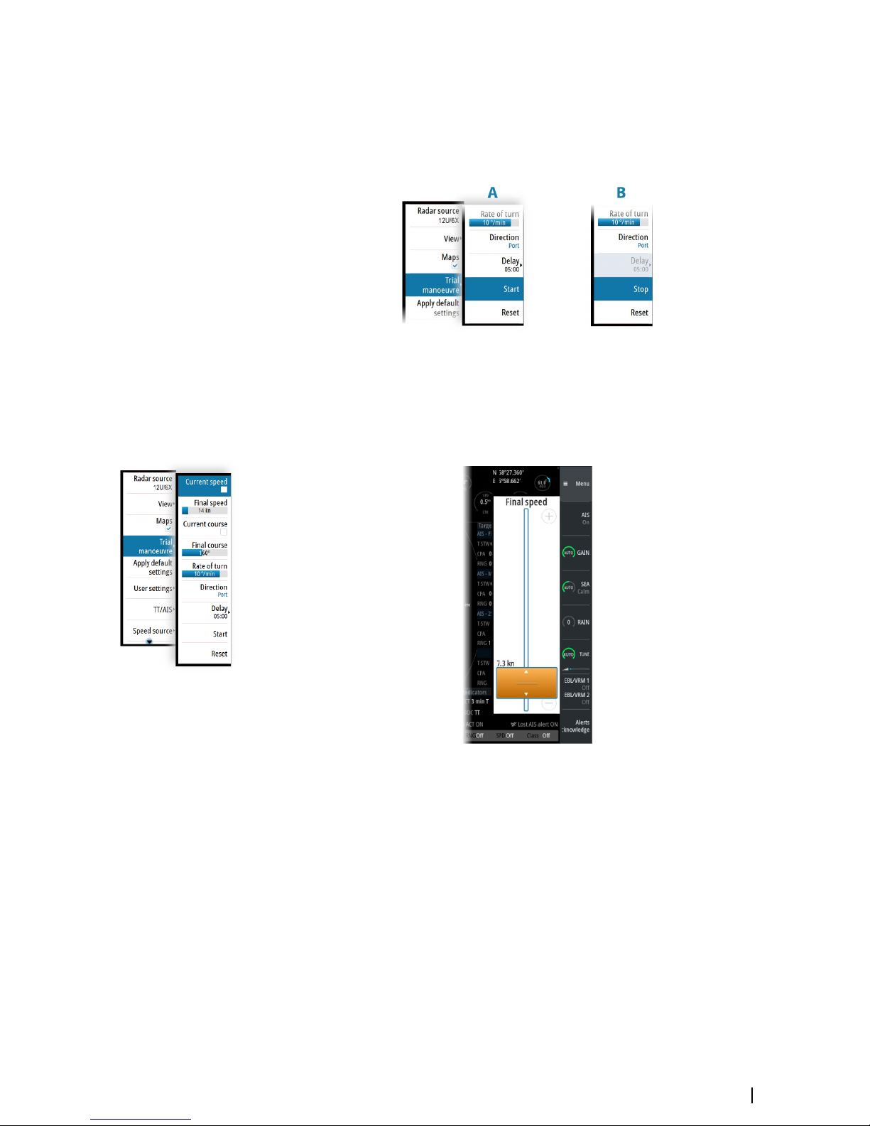
Starting and stopping the trial maneuver
You can start the trial maneuver from the menu when the final speed or final course is
defined.
You can at any time stop the trial maneuver. The function will automatically stop when the
delay time has expired.
Manually changing the trial maneuver settings
The default trial maneuver settings are defined during commissioning of the vessel.
The trial maneuver settings menu remains open after the function is started. If a maneuver is
considered dangerous, you can adjust the speed and/or course to see how to avoid a
dangerous situation.
Trial maneuver | R5000 Operator manual
57
Page 58

Maintenance
General
The system requires very little maintenance. The operator should inspect the equipment
carefully and notice every possible anomaly, such as the integrity of the equipment, the
presence of rust, missing paint, and loose screws. Monthly the operator should clean the
equipment and remove dust, ash and grease with a soft cotton cloth and alcohol. Caution
must be taken not to use solvent to clean plastic parts.
For details about replaceable parts, refer to the separate installation manual(s).
Performance monitor
The performance monitor (PM) function is used for checking the performance of the
transceiver, the waveguide and the antenna.
Before the function is started you should set the range scale to 24 NM, tune the radar and
adjust the gain control to about 90%.
In this condition an intensified noise ring, positioned approximately at 24 NM should appear.
The distance of the ring from the center is directly proportional to the TXRX transmitted
output power. When the Magnetron has decreased 10 dB in peak power, the ring’s distance
will decrease to about 12 NM range.
The performance monitor is started from the main menu.
The performance monitor ring should have a missing angular sector of some 60° to 80°. This
missing sector is due to the RF beam really transmitted by the antenna. Any RF power
degradation between the magnetron and the antenna output results in a smaller angular
ring interruption. When the angular sector is reduced below 30°, the antenna section
requires service. The ring’s width (thickness) is proportional to the tuning condition. The
width of the ring for a good and correctly tuned radar will be approximately 2 NM. The ring’s
strength (difference between background noise and ring’s noise) indicates the receiver noise
figure. If the receiver noise figure degradation is more than 10 dB, it is not possible to
distinguish the performance monitor ring from the background noise.
Ú
Note: If sector blanking is enabled, the performance monitor ring will have missing
sectors in the sector blanking areas.
14
58
Maintenance | R5000 Operator manual
Page 59

Radar data
The Radar data dialog displays status for vital radar components.
The system displays an alert when the magnetron has to be replaced.
For replacement procedures refer to the separate Commissioning manual.
Maintenance | R5000 Operator manual
59
Page 60

The alert system
The system continuously checks for dangerous situations and system faults while running.
Type of alerts
There are 3 alert types in the system:
• Alarms: This is the system's highest priority alert, activated when a situation occurs that
might result in a collision, or for conditions that critically effect the capability or
performance of the system. An alarm is accompanied by an audible signal, and the alarm
icon flashes until the alarm is acknowledged.
• Warnings: These are lower priority alerts, announcing conditions that could result in
unwanted system response or eventual failure if no action is taken. A warning is
accompanied by an audible signal (2 short signals, repeated as a Warning if not
acknowledged). The warning icon flashes until the warning is acknowledged.
• Cautions: This is information about danger and caution objects that require attention.
Cautions have no audible signal.
Alert categories
Each alert is - in addition to alert type - identified with an alert category. An alert's category
decides the action required to rectify the alert.
Category
Action
A
Category A alerts can only be acknowledged on the radar control station.
In general, all local alarms generated by a workstation are category A. Example:
Danger AIS target alarm.
B
Category B alerts can be acknowledged on the BNWAS or BAM if these systems are
connected.
All global alarms generated by navigation systems are category B. Example: Gyro
failure warning.
Alert notifications
When an alert is triggered, the alert appears in the Alerts panel.
The alerts are displayed in a sorted order. The sort order is first by state (i.e. not
acknowledged before rectified before acknowledged), then severity (i.e. alarm before
caution), then age.
Alarms and Warnings have different states:
• Active - not acknowledged, not silenced
• Active - not acknowledged, silenced
• Active - acknowledged
• Active - responsibility transferred to another work station
• Rectified - not acknowledged
When an alert has been both rectified and acknowledged, it will disappear from the Alerts
panel.
Cautions cannot be acknowledged, and they disappear from the alert list when the condition
is rectified.
A number of related alerts are aggregated and shown in the Alerts panel as one single item
with the aggregation symbol (+) next to the alert symbol. The aggregated symbol shows the
state as unacknowledged if at least one alert in the aggregated list is unacknowledged. Each
alert in the list has to be acknowledged individually.
The table below shows alert icons and behavior depending on alert state.
15
60
The alert system | R5000 Operator manual
Page 61

Alert type Icon State Indication
Alarm
Active - not
acknowledged, not
silenced
• Flashing symbol
and descriptive
text
• Audible signal
Active - not
acknowledged,
silenced
• Flashing symbol
and descriptive
text
• No audible signal
Active acknowledged
• Steady symbol and
descriptive text
• No audible signal
Active - responsibility
transferred
• Steady symbol and
descriptive text
• No audible signal
Rectified - not
acknowledged
• Flashing symbol
and descriptive
text
• No audible signal
Warning
Active - not
acknowledged, not
silenced
• Flashing symbol
and descriptive
text
• Audible signal
Active - not
acknowledged,
silenced
• Flashing symbol
and descriptive
text
• No audible signal
Active acknowledged
• Steady symbol and
descriptive text
• No audible signal
Active - responsibility
transferred
• Steady symbol and
descriptive text
• No audible signal
Rectified - not
acknowledged
• Flashing symbol
and descriptive
text
• No audible signal
Caution Active
• Steady symbol and
descriptive text
• No audible signal
The alert system | R5000 Operator manual
61
Page 62

Alert type Icon State Indication
Alarm
Active - not
acknowledged, not
silenced
• Flashing symbol
and descriptive
text
• Audible signal
Active acknowledged
• Steady symbol and
descriptive text
• No audible signal
Rectified - not
acknowledged
• Flashing symbol
and descriptive
text
• No audible signal
Warning
Active - not
acknowledged, not
silenced
• Flashing symbol
and descriptive
text
• Audible signal
Active - not
acknowledged,
silenced
• Flashing symbol
and descriptive
text
• No audible signal
Active acknowledged
• Steady symbol and
descriptive text
• No audible signal
Active - responsibility
transferred
• Steady symbol and
descriptive text
• No audible signal
Rectified - not
acknowledged
• Flashing symbol
and descriptive
text
• No audible signal
Caution Active
• Steady symbol and
descriptive text
• No audible signal
62
The alert system | R5000 Operator manual
Page 63

Siren enabled
By default, the audible alert signal is turned ON.
You can select to disable the audible signal when service mode is active, but the audible
signal will be enabled when service mode is deactivated.
The Alerts dialog
The Alerts dialog includes a list of active alerts together with a historic listing of the last alert
state changes. Entries are added to the history whenever an alert is raised, acknowledged,
rectified or cleared.
All alerts in the Alerts dialog include a time stamp.
External bridge alert systems
The system supports Bridge Alert Management (BAM) and Bridge Navigational Watch Alarm
Systems (BNWAS).
Bridge Alert Management (BAM)
All system alerts are transferred to the bridge alert system if this is connected to the system.
An alert generated by the system - e.g. Danger target alarm - can only be acknowledged
from the system itself. Global alarms - e.g. Position timeout or Gyro failure - can be
acknowledged on both the system control unit and on the bridge alert system.
Bridge Navigational Watch Alarm Systems (BNWAS)
If a BNWAS is connected to the system, the system outputs an EVE sentence to the BNWAS
when a user interaction with the system occurs. The EVE sentence remotely resets the
BNWAS timer to confirm wheelhouse crew activity.
The alert system | R5000 Operator manual
63
Page 64

Alphabetic alert list
Alert type abbreviations:
• C: Caution
• W: Warning
• A: Alarm
Alert text Description Type
Category
AIS Capacity 95%
AIS target processing/displaying is about to be
exceeded.
C B
AIS Capacity Full AIS capacity exceeded. W A
AIS FAIL
AIS failure W B
Not used AIS failure C B
AIS TGT in GZ AIS Target in Guard zone W A
AIS TGT Lost: # AIS target # is lost W A
BAM HBT Lost BAM Heartbeat lost C B
Dangerous AIS
TGT
CPA or TCPA values of an activated AIS target less
than set limits
A A
Dangerous TT
CPA or TCPA values of a tracked target less than
set limits
A A
Door switch open The radar enclosure is open due to maintenance.
The radar is not operational
A A
EPFS FAIL
Not used position source failure C B
Position source failure W B
Geodetic Datum
FAIL
Geodetic Datum failure W B
GYRO FAIL
Gyro failure W B
Not used gyro failure C B
Heading Line FAIL Heading line failure W B
Magnetron EOL Magnetron end of life reached C B
POSN Invalid Position invalid W B
POSN Unavailable Position unavailable W B
Radar Antenna
FAIL
Radar antenna failure W B
RADAR FAIL Radar TXRX failure W B
REF TGT Lost Reference target lost W A
Safety switch open The safety switch is open due to maintenance.
The radar is not operational
A A
SOG FAIL Speed Over Ground failure W B
Speed LOG FAIL
Not used speed LOG failure C B
Speed LOG failure W B
SPD Long. Axis
FAIL
Speed longitudinal axis data failure W B
SPD Tran. Axis FAIL Speed transversal axis data failure W B
STW FAIL Speed Through Water failure W B
Test alarm The Test alarm is enabled to verify audible alarm
operation
A A
TGT in GZ Tracked target # within the vessel's guard zone W A
64
The alert system | R5000 Operator manual
Page 65

Alert text Description Type
Category
Train TGT CPA FAIL Training target CPA out of range W A
Train TGT TCPA
FAIL
Training target TCPA out of range W A
Trigger FAIL Trigger failure W B
TT Capacity 95%
Tracked target processing/displaying is about to
be exceeded
C B
TT Capacity Full Tracked target capacity exceeded W A
TT Lost: # Tracked target # is lost W A
UTC Data FAIL UTC data failure W B
Radar Video FAIL Radar video failure W B
Operating modes fallback
The following table shows possible failure categories, and which operations that are allowed
or not allowed when the failure occurs.
Failure Possible alert Fallback
arrangement
Function Inhibited
Heading failure GYRO FAIL
Automatic
switch to relative
motion head-up
mode
• AIS
• Acquiring/Tracking radar targets
• Geographically referenced maps
• North Up/Course Up orientation
• True motion presentation
• True trails
Speed through
water failure
Speed LOG FAIL
STW FAIL
Possible to set
Manual speed
• AIS
Course and
speed over
ground failure
Speed LOG FAIL
SOG FAIL
EPFS speed FAIL
Automatic
switch to relative
motion, relative
vectors and sea
stabilization
• True vectors
• Geographically referenced maps
• True motion presentation
• True trails
Position input
failure
POSN Invalid
POSN
Unavailable
• AIS
• Geographically referenced maps
Radar video
input failure
RADAR FAIL
Possible to
display target
information
based on AIS
data
• Acquiring/tracking radar targets
• True motion/ True trails
• Radar video presentation
AIS input failure AIS FAIL
• AIS
The alert system | R5000 Operator manual
65
Page 66

Menu overview
Main menu
> Access submenu
... Open dialog
Level 1 Level 2
Radar source
View > Trials & PAST POSN >
Orientation
Motion mode
Reset offset
Offset >
Vectors >
Cursor bearing
Brilliance >
Maps
Trial maneuver > Current speed
Final speed
Current course
Final course
Rate of turn
Direction
Delay >
Start
Reset
Apply default settings
User settings > Save settings >
Load settings >
TT/AIS >
Cancel all
Cancel selected target
Lost warning
Range
CPA/TCPA limit ...
AIS >
Data ...
Target ASSOC >
Training
Speed source > Stabilization
Source
Manual speed
Drift/Set
Drift
16
66
Menu overview | R5000 Operator manual
Page 67

Level 1 Level 2
Set
PPI symbols > PI lines >
Maps ...
Range rings
Heading line
Overlay graphic off
PI1 BRG Reset
PI2 BRG Reset
PI3 BRG Reset
PI4 BRG Reset
Zones Zone 1
Adjust
Type
Zone 2
Adjust
Type
PM
Advanced > IR
Noise rejection
Target boost
TGT expansion
Fast scan mode
Settings
Settings menu
> Access submenu
... Open dialog
Level 1 Level 2
Access control Service mode
Enter password ...
System Key beeps
Time ...
Remote controller
Restore defaults ...
Files ...
Advanced ...
Reboot device
Registration ...
About
Radar Installation
Radar video palette
Target trails palette
Menu overview | R5000 Operator manual
67
Page 68

Level 1 Level 2
Radar data
Expanded PPI
Position Satellites
Ignore position quality
Alerts Siren enabled
Alerts ...
Test alarm
Units Distance small
Own vessel rate of turn
Network Info
Control display units ...
Sources ...
Priorities table ...
Device list
Diagnostics
NMEA 0183 >
Own ship Setup ...
MMSI
Own ship AIS data
Trial maneuver
Simulator Simulate
Demo mode
Files ...
Advanced ...
68
Menu overview | R5000 Operator manual
Page 69

O2000/O5000 Trackball, key function
comparison
Most functions can be operated both with the O2000 controller and with the O5000
Trackball unit.
The table gives an overview of key operation for both units.
Ú
Note: The cursor must be located over an open menu or over the quick access pop-up
to be able to use the scroll function.
Action O5000 Trackball unit O2000
Operate menu
Activate Left key Enter key - single press
Scroll Scroll wheel Rotary knob or arrow keys
Return to previous level Right key Exit key - single press
Exit Left key outside menu area Exit key - press and hold
Operate quick access keys
Select Left key
Open pop-up Right key
Close pop-up Right key
Scroll pop-up options Scroll wheel
Select target
Activate/de-activate AIS
target
Left key Enter key - single press
Acquire radar target Left key Enter key - single press
Display target menu Right key Enter key - press and hold
17
O2000/O5000 Trackball, key function comparison | R5000 Operator manual
69
Page 70

Target symbols
This section lists the target symbols used in this system.
Symbol Description
AIS Base station
AIS SAR aircraft
AIS SAR vessel
AIS SART (AIS Search And Rescue Transmitter)
AIS target - Dangerous, indicated with bold line and with red
color. The symbol flashes until the target alarm is acknowledged by
the operator
AIS target - Lost, indicated with crossed lines centered on the
target symbol. The symbol is located at the last received position
from the target
AIS target - Selected, indicated with a square (dotted line) around
the target symbol
AIS target - Sleeping, aligned with received heading information
or with COG information if heading is not available
AIS target, activated - True scaled outlines
AIS target with heading line and SOG/COG (dotted line), and with
indicated turn direction
AIS target with heading line, SOG/COG (dotted line) and past track
Associated target - using AIS data
Associated target - using radar data
Physical AIS AtoN, basic shape (AIS aids to navigation)
Physical AIS AtoN - East cardinal mark
Physical AIS AtoN - Emergency wreck mark
18
70
Target symbols | R5000 Operator manual
Page 71

Symbol Description
Physical AIS AtoN - Isolated danger
Physical AIS AtoN - North cardinal mark
+
Off Posn
Physical AIS AtoN - Off position
Physical AIS AtoN - Port hand mark
Racon err
Physical AIS AtoN - Racon failure
Physical AIS AtoN - Racon
Physical AIS AtoN - Safe water
Physical AIS AtoN - South cardinal mark
Physical AIS AtoN - Special mark
Physical AIS AtoN - Starboard hand mark
Unlit
Physical AIS AtoN - Unlit (failure of lights)
Physical AIS AtoN - West cardinal mark
Radar target - Dangerous, indicated with bold line and with red
color. The symbol flashes until the target alarm is acknowledged by
the operator. It remains red until the system no longer defines it as a
dangerous target
Radar target - in acquisition state, indicated as a broken circle
centered at the position of target acquisition
Radar target - Lost, indicated with crossed lines centered on the
target symbol. The symbol is located at the last received position
from the target
Radar target - Selected, indicated with a square (dotted line)
around the target symbol
Radar target - Tracked, with velocity vector
Target symbols | R5000 Operator manual
71
Page 72

Symbol Description
18
Radar target with past position and velocity vector
R
Reference target
SS
Signal station
+
Virtual AIS AtoN, basic shape
+
Virtual AIS AtoN - East cardinal mark
+
Virtual AIS AtoN - Emergency wreck mark
+
Virtual AIS AtoN - Isolated danger
+
Virtual AIS AtoN - North cardinal mark
+
Virtual AIS AtoN - Port hand mark
+
Virtual AIS AtoN - Safe water
+
Virtual AIS AtoN - South cardinal mark
+
Virtual AIS AtoN - Special mark
+
Virtual AIS AtoN - Starboard hand mark
+
Virtual AIS AtoN - West cardinal mark
Missing
Virtual AIS AtoN Missing
72
Target symbols | R5000 Operator manual
Page 73

Terms and abbreviations
ACK Acknowledge
ACQ Acquire
ACT Activate
ADJ Adjust, Adjustment
ALT Altitude
AIS Automatic Identification System
AM Amplitude Modulation
ANCH Anchor Watch
ANT Antenna
AP Autopilot
APR April
ARPA Automatic Radar Plotting Aid
ATON Aid to Navigation
AUD Audible
AUTO Automatic
AZ Acquisition Zone
AZI Azimuth Indicator
BCR Bow Crossing Range
BCT Bow Crossing Time
BKGND Background
BMD Brush Motor Drive - brushless controller for the S_Band
BRG Bearing
BRILL Display Brilliance
BWW Bearing Waypoint To Waypoint
C UP Course Up
CCRP Consistent Common Reference Point
CENT Centre
CNCL Cancel
COG Course Over Ground
CONT Contrast
CPA Closest Point Of Approach
CPU Central Processing Unit
CRS Course
CTS Course To Steer
CURS Cursor
DAY/NT Day/Night
DECR Decrease
DEG Degrees
DEL Delete
DGPS Differential Gps
DISP Display
DIST Distance
DPTH Depth
19
Terms and abbreviations | R5000 Operator manual
73
Page 74

DR Dead Reckoning
DSC Digital Selective Calling
DW Deep Water
EBL Electronic Bearing Line
ECDIS Electronic Chart Display And Information System
ECS Electronic Chart System
EGNOS European Geo-Stationary Navigational Overlay System
ENCSOG Automatic Navigational Chart
EP Estimated Position
EPFS Electronic Position Fixing System
EPIRB Emergency Position Indicating Radio Beacon
EQUIP Equipment
ERBL Automatic Range And Bearing Line
ETA Estimated Time Of Arrival
ETD Estimated Time Of Departure
EZ Exclusion Zone
FK User Function Key
FMCW Frequency Modulated Continuous Wave
FS Fast Scan
FWD Forward
GAS Grounding Avoidance System
GEOG Geographic
GLONASS Global Orbiting Navigation Satellite System
GMDSS Global Maritime Distress And Safety System
GND TRK Ground Track
GNDSTAB Ground Stabilized
GNSS Global Navigation Satellite System
GPS Global Positioning System
GZ Guard Zone
H UP Head Up
HDG Heading
HL Heading Line
HR Hours
I/O Input/Output
IBS Integrated Bridge System
ID Identification
IN Input
INIT Initialization
INS Integrated Navigation System
IR Interference Rejection
IRCS Integrated Radio Communication System
ISW Interswitch
Km Kilometer
KN Knots
LBL Label
74
Terms and abbreviations | R5000 Operator manual
Page 75

LIM Limit
LOST TGT Lost Target
LP Long Pulse
m Meters
MIN Minimum
MIN Minutes
MKR Marker
MOB Man Over Board
MP Medium Pulse
MSTR Master
N UP North Up
NAV Navigation
NC Normally Closed
NLT Not Less Than
NM Nautical Mile
NMT Not More Than
NR Noise Rejection
NUC Not Under Command
OFF CENT Off Centre
OFFTRK Off Track
OS Own Ship
OUT Output
PAD Predicted Area Of Danger
PAST POSN Past Position
PCB Printed Circuit Board
PI Parallel Index Line
PL Pulse Length
PM Performance Monitor
POSN Position
PPC Predicted Point Of Collision
PPI Plan Position Indicator
PRF Pulse Repetition Frequency
PWR PWR
R BRG Relative Bearing
R CRS Relative Course
R VECT Relative Vector
RAD Radius
RAIN Anti Clutter Rain
RCDS Raster Chart Display System
REF Echo Reference
REF SOG Echo Reference Speed
REL or R Relative
RM Relative Motion
RM (R) Relative Motion (Relative Trails)
RM (T) Relative Motion (True Trails)
Terms and abbreviations | R5000 Operator manual
75
Page 76

RNC Raster Navigational Chart
RNG Range
ROT Rate Of Turn
RR Range Rings
RTE Route
RX Receiver
SAF CON Safety Contour
SAR Search And Rescue
SC/SC Scan To Scan
SDME Speed and Distance Measuring Equipment
SEA Anti Clutter Sea
SEL Select
SENC System Electronic Navigational Chart
SNR Signal To Noise Ratio
SOG Speed Over Ground
SP Short Pulse
SPD Speed
SRNC System Raster Navigational
SRT Small Radar Transceiver
STAB Stabilized
STBD Starboard
STC Sensitivity Time Control
STW Speed Through Water
T BRG True Bearing
T CRS True Course
T SPD True Speed
T VECT True Vector
TB Target Boost
TCPA Time To Closest Point Of Approach
TE Target Expand
TGT Target
Tgt exp Target expansion
Th Target threshold
TM True Motion
TPR Transponder
TRIAL Trial Maneuver
TRIG Trigger Pulse
TRK Track
TRKG Tracking
Tracking Time To Go
TS Target separation
TWOL Time To Wheel Over Line
TX Transmit, Transmitter
TX/RX Transceiver
UPS Uninterruptible Power Supply
76
Terms and abbreviations | R5000 Operator manual
Page 77

VRM Variable Range Marker
VTS Vessel Traffic Services
WOL Wheel Over Line
WOP Wheel Over Point
Terms and abbreviations | R5000 Operator manual
77
Page 78

Technical specifications
The most up-to-date specifications list is available at:
• www.navico-commercial.com
Ú
Note: Hardware specifications for the individual units included in the system are found
in the documentation following the units.
General
Description
Type-approved X- and S-Band radar systems
aboard CAT 1, CAT 2 and CAT 3 SOLAS
vessels, including high-speed craft
Standards • IMO-Resolution A.278 (VIII), A.694 (17), A.
823 (19), MSC 191 (79), MSC 192 (79)
• EN 62388 Ed.2.0, 2014
• EN 62288 Ed.2.0, 2014
• EN 60945 Ed.4.0, 2002 incl. Corr.1, 2008
• EN 61162-1 Ed.4.0, 2010
• EN 61162-2 Ed.1.0, 1999
Type approval European Council Directive 2014/90/EU on
Marine Equipment modified by Commission
Implementing Regulation (EU) 2018/773
(May 2018) - Wheelmark
Performance
RPM >20 and >40
Nominal peak power
X-band up-mast 12 kW or 25 kW depending on transceiver
X-band down-mast 25 kW
S-band 30 kW
Operating frequency
X-band 9410 ± 30 MHz
S-band 3050 ± 30 MHz
Pulse length
Short pulse 60 ns (25 kW, 30 kW), 80 ns (12 kW)
Medium pulse 250 ns
Long pulse 800 ns
PRF
Short pulse 3000 Hz
Medium pulse 1500 Hz
Long pulse 750 Hz
Modulator MOSFET Solid State
IF amplifier Logarithmic
IF dynamic 95 dB
IF center frequency 60 MHz
IF bandwidth
Short pulse 24 MHz
20
78
Technical specifications | R5000 Operator manual
Page 79

Medium pulse 5 MHz
Long pulse 2 MHz
Horizontal Beam width 1.35°
Vertical Beam width 22°
VSWR < 1.20
Overall noise figure < 5 nominal dB
MDS on long pulse -105 dBm
Display features
Presentation mode Day or Night
Typical viewing distance (m)
16" 0.75
19", 24", 27" 1.00
Resolution (pixels)
16", 19" 1366x768
24", 27" 1920x1080
PPI Diameter (mm)
16" 180
19" 210
24" 280
27" 320
Short range
Available scales 1/8, 1/4, 1/2, 3/4, 1.5 and 3 NM
Range video resolution 11.25 m
Azimuth on-screen resolution 0.1°
Medium range
Available scales 6 and 12 NM
Range video resolution 45 m
Azimuth on-screen resolution 0.1°
Long range
Available scales 24, 36, 48, 64, 72 NM
Range video resolution 125 m
Azimuth on-screen resolution 0.1°
Relative Motion (RM)
Head up (HU), Course up (CU) and North up
(NU)
True Motion (TM) Course up (CU) and North up (NU)
Off-centering Up to 75% of range scale in use
Cursor
Polar and Geographical coordinates,
continuously displayed when cursor is
activated
Target tracking
Acquisition Manual and automatic, up to 100 targets
Tracking Manual and automatic, up to 100 targets
Technical specifications | R5000 Operator manual
79
Page 80

Tracking range 24 NM
AIS
Presentation
• Maximum 300 target (all can be activated)
• AIS overflow mechanism of priority
Safe checking 300 targets in total
Mapping
Map drawing
Operator compiled maps
• Up to 32 maps, each may contain up to
120 segments and 32 symbols
• Selectable colors and line styles
Map stabilization
• Relative
• Geographic
Map storage
• By name
• Built-In non-volatile memory used
• SD Card transfer available
Map adjustments
• Rotate
• Shift
Parallel index Four independent parallel index lines
Data readout
• Own ship data
• Target tracking data
• AIS target data
80
Technical specifications | R5000 Operator manual
Page 81

Page 82

*988-12294-002*
www.navico.com/commercial
 Loading...