

Page 1

ENGLISH
R3016 12U/6X
Installation Manual
www.navico.com/commercial
Page 2

Page 3

Preface
Disclaimer
As Navico is continuously improving this product, we retain the right to make changes to the
product at any time which may not be reflected in this version of the manual. Please contact
your nearest distributor if you require any further assistance.
It is the owner’s sole responsibility to install and use the equipment in a manner that will not
cause accidents, personal injury or property damage. The user of this product is solely
responsible for observing maritime safety practices.
NAVICO HOLDING AS AND ITS SUBSIDIARIES, BRANCHES AND AFFILIATES DISCLAIM ALL
LIABILITY FOR ANY USE OF THIS PRODUCT IN A WAY THAT MAY CAUSE ACCIDENTS, DAMAGE
OR THAT MAY VIOLATE THE LAW.
This manual represents the product as at the time of printing. Navico Holding AS and its
subsidiaries, branches and affiliates reserve the right to make changes to specifications
without notice.
Governing Language
This statement, any instruction manuals, user guides and other information relating to the
product (Documentation) may be translated to, or has been translated from, another
language (Translation). In the event of any conflict between any Translation of the
Documentation, the English language version of the Documentation will be the official
version of the Documentation.
Copyright
Copyright © 2016 Navico Holding AS.
Warranty
The warranty card is supplied as a separate document.
In case of any queries, refer to the brand website of your display or system: www.navico.com/
commercial.
Regulatory statements
This equipment is intended for use in international waters as well as coastal sea areas
administrated by member states pursuant to international conventions.
The R3016 12U/6X Radar system complies with:
• the Navigation requirements of Marine equipment directive (MED) 96/98/EC, and the last
modification by directive 2015/559/EU, Annex A.1. item 4.36, Radar equipment for CAT 3
vessels.
The relevant Declaration of Conformity is available on the product's section on the following
website: www.navico.com/commercial.
Wheelmark
The Marine Equipment Directive 96/98/EC (MED) applies to all ships for which safety
certificates are issued by - or on behalf of - member states pursuant to international
conventions. This applies to all new ships, to existing ships not previously carrying such
equipment, and to ships having their equipment replaced. This means that all system
components covered by annex A1 must be type-approved accordingly and must carry the
Wheelmark, which is a symbol of conformity with the Marine Equipment Directive.
Navico has no responsibility for incorrect installation or use of the equipment. It is essential
for the person in charge of the installation to be familiar with the relevant requirements as
well as with the contents of the manuals, which covers correct installation and use.
Preface | R3016 12U/6X Installation manual
3
Page 4

About this manual
This manual is a reference guide for installing the R3016 12U/6X radar system. The manual is
written for the professional radar and marine electronics technicians, and assumes some
prior knowledge and skills relevant to the type of work to be carried out.
The latest available manual version can be downloaded from the website: www.navico.com/
commercial.
Safety precautions
Safety precautions described in this section are applicable to the radar system. They are
general safety precautions that are not related to any specific procedure, and they might
therefore not appear elsewhere in this manual. They are recommended precautions that
personnel must understand and apply during operation and maintenance of the system.
You are obliged to read these operating instructions prior to operation, and to adhere to the
operating instructions in order to prevent possible danger. Prevention of danger includes
that operator personnel are trained and authorized for safe operation of the equipment. We
assume no liability for damage due to improper operation which could have been
prevented.
The system must only be operated by persons who have passed the relevant mandatory
training on the respective systems and applications. Only reading these operating
instructions cannot replace such training. Persons authorized to operate, maintain and
troubleshoot the system are instructed and trained by Simrad. Persons operating or servicing
this radar system must be familiar with the general safety regulations and specific safety
systems, and they must have passed all required training. They must have read the relevant
operating instructions and manuals before starting to work.
Have these operating instructions always at hand on all relevant locations, and ensure that
copies are available to all operators. Operating personnel must at all times follow all safety
regulations.
During normal operation, the unit can be quickly disconnected from the main power line by
turning OFF the relevant circuit breaker located on the electric switchboard.
Do not replace components or make adjustments inside the unit when the voltage supply is
turned ON. Always remove power and discharge to ground a circuit before touching it.
Under no circumstances should any person initiate servicing or repairing the unit except in
the presence of a qualified person.
Ensure unobstructed access to all operator panels, controls, and relevant switchgear cabinets
in order to enable instant response to alarms.
Whenever it is necessary to disconnect the waveguide from a radar transmitter for
maintenance purpose, the transmitter output should be terminated with a matched load. If
this is not possible, care should be taken. Do not stand in front of an open-ended waveguide
from which power is being radiated.
Ú
Note:
Main power is always present on the terminal board unless the main break from
the power distribution panel of the vessel is turned off.
Warning: Never look down a waveguide from which power is being
radiated!
Warnings
High voltage
Radar equipment includes high voltage that can cause injury or loss of life. Danger exists only
when the units are opened, exposing internal circuits, as when servicing the equipment.
This radar has been carefully designed to protect personnel from possible injury from high
voltages. Although every effort has been made to eliminate danger to personnel, no
responsibility is accepted for any injury or loss of life suffered in connection with this
equipment.
4
Preface | R3016 12U/6X Installation manual
Page 5

Radio frequency radiation
Harmful effects (particularly to the eyes) may be caused by exposure of any part of the
human body to high power radio frequency radiation.
Hazard distances are given in the following table:
Configuration
Distance 100 W/m
2
point (m)
Distance 50 W/m
2
point (m)
Distance 10 W/m
2
point (m)
12 kW Transceiver +
6 ft. antenna
- 0.05 0.9
The system is however designed to always disable the microwave radiation when the
antenna is not rotating.
X-Ray radiation
This radar system does not generate X-ray radiation.
Trademarks
Simrad® is used by license from Kongsberg.
NMEA® and NMEA 2000® are registered trademarks of the National Marine Electronics
Association.
SD™ and microSD™ are trademarks or registered trademarks of SD-3C, LLC in the United
States, other countries or both.
Preface
| R3016 12U/6X Installation manual
5
Page 6

Contents
7 Introduction
7 R3016 12U/6X Radar system
7 System components
8 R3016 12U/6X manuals
9 Connector layouts
9 Up-mast transceiver connectors
9 R3016 Сontrol unit connectors
10 R3000 power supply unit connectors
11 Installation overview
11 Interference
12 Obstructions and blind sectors
12 Transceiver height implications
13 Mounting location
13 Tools required
14 Hardware mounting
14 Install the up-mast transceiver
15 Fitting the control unit
16 Install the R3000 power supply unit
18 Adding the heater system (optional)
21 Install the SI80
22 Wiring
22 General precautions
22 System overview diagram
22 Up-mast transceiver cables
23 Up-mast transceiver grounding
23 Connection at the up-mast transceiver
24 Transceiver power supply connection
25 Power supply diagnostics
25 Control unit power and alarm output connection
26 Connection of Ethernet cable to control unit
26 Sensor connection
27 Serial ports – color code
29 SI80 connection
29 VDR connection
31 Technical specifications
35 Spare parts
36 Accessories
37 Dimensional drawings
37 Up-mast transceiver and antennas
37 R3000 Power supply unit
38 R3016 Control unit
38 SI80 Signal Interface unit
38 Antenna rotating diameter
39 Technical drawings
39 System block diagram
6
Contents | R3016 12U/6X Installation manual
Page 7
Introduction
R3016 12U/6X Radar system
The R3016 12U/6X Radar system is a type approved radar system conforming to the
International Maritime Organization (IMO) requirements for vessels that are subject to SOLAS
regulations.
The system consists of:
• R3016 Control unit
• 12kW up-mast transceiver with 6ft. antenna
• R3000 Power supply unit
The radar assists in safe navigation and in avoiding collision by providing an indication, in
relation to own ship, of the position of other surface craft, obstructions and hazards,
navigation objects and shorelines. For this purpose, the radar provides the integration and
display of radar video, target tracking information, positional data derived from own ship’s
position and geo-referenced data.
To be able to provide consistent data, the R3016 12U/6X Radar system is designed to be
integrated using serial interfaces with other electronic equipment normally present in a
vessel bridge:
• Gyro-compass or transmitting heading device (HDG)
• Speed and Distance Measuring Equipment (SDME)
• Electronic Position Fixing System (EPFS)
• Automatic Identification System (AIS)
• Bridge Alert Management system (BAM)
The R3016 12U/6X Radar system is a Category 3 type approved system, approved only in the
configuration specified in the certificate. The type approval certificates are available at the
product web site: www.navico.com/commercial.
System components
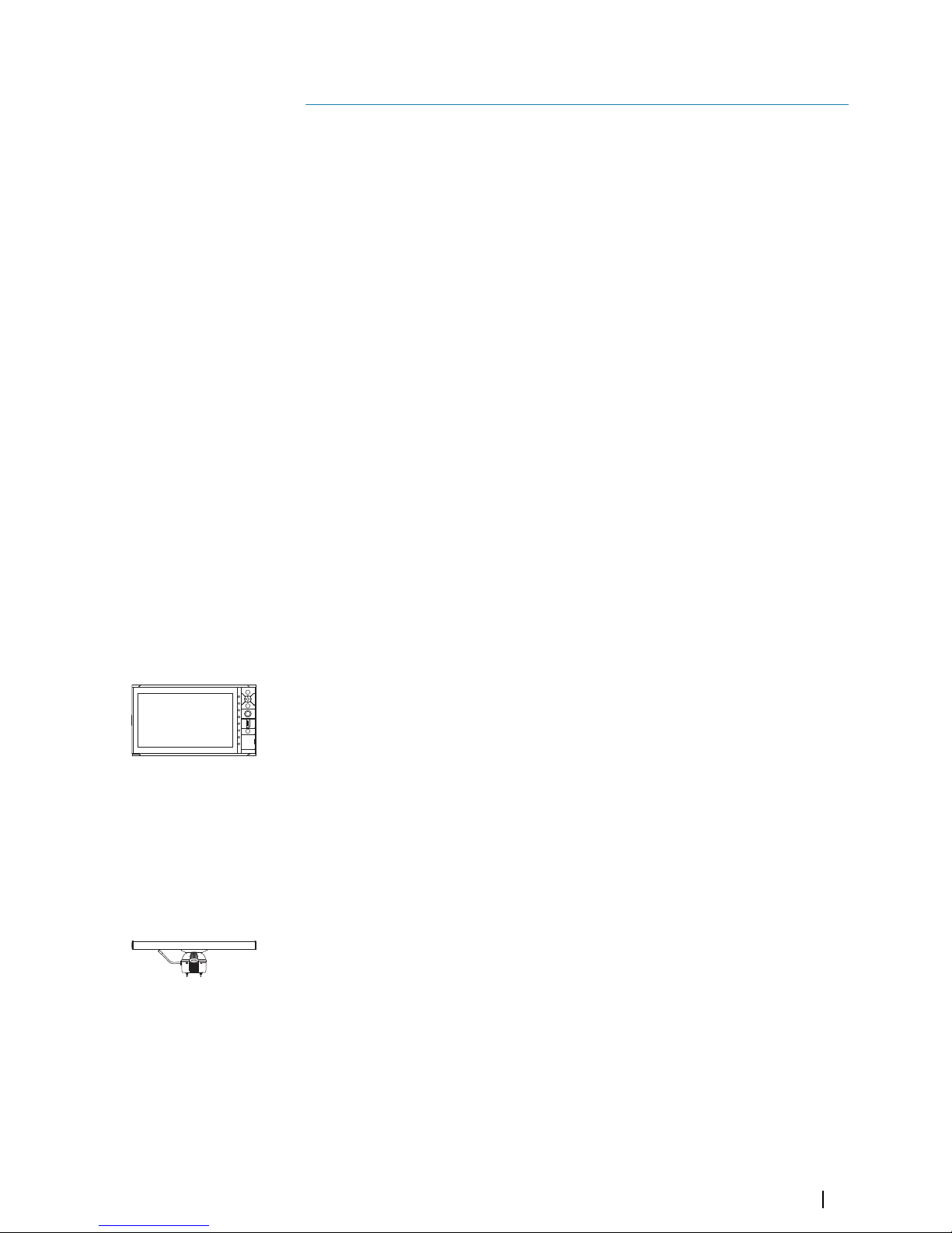
The R3016 Control unit
The R3016 Control unit includes 3 main components: a processor, a monitor and a keypad.
The processor is made of a dual core CPU that integrates information coming from the
transceiver and the external sensors.
The monitor is a non-touch monitor type approved for Category 3 Radar use.
The keypad is the main control device for the system. The system cursor is controlled by the
directional pad, while several options are provided to activate radar functionalities and
navigate menus during operation.
The R3016 Control unit is fitted with an SD card reader used for updating the software and
for transferring data from the system.
The control unit is directly linked with the transceiver using a dedicated signal cable (15, 30
or 65 m length).
The up-mast radar sensor
The up-mast radar sensor comprises two main parts: a 6 foot antenna and a 12 kW
transceiver.
The antenna is a 6 foot X-band antenna, fixed to the transceiver unit with 4 bolts.
The transceiver is the system radio transmitter and receiver, measuring the radar echo
received from the pulse transmission. The transceiver includes a processing unit that
eliminates unwanted echoes or noise, and transfers digitized video data to the control unit.
On the back of the unit there is a safety switch and 3 connectors: Signal connector, Main
power connector, and a connector for the optional Heater kit.
+
_
1
Introduction
| R3016 12U/6X Installation manual
7
Page 8
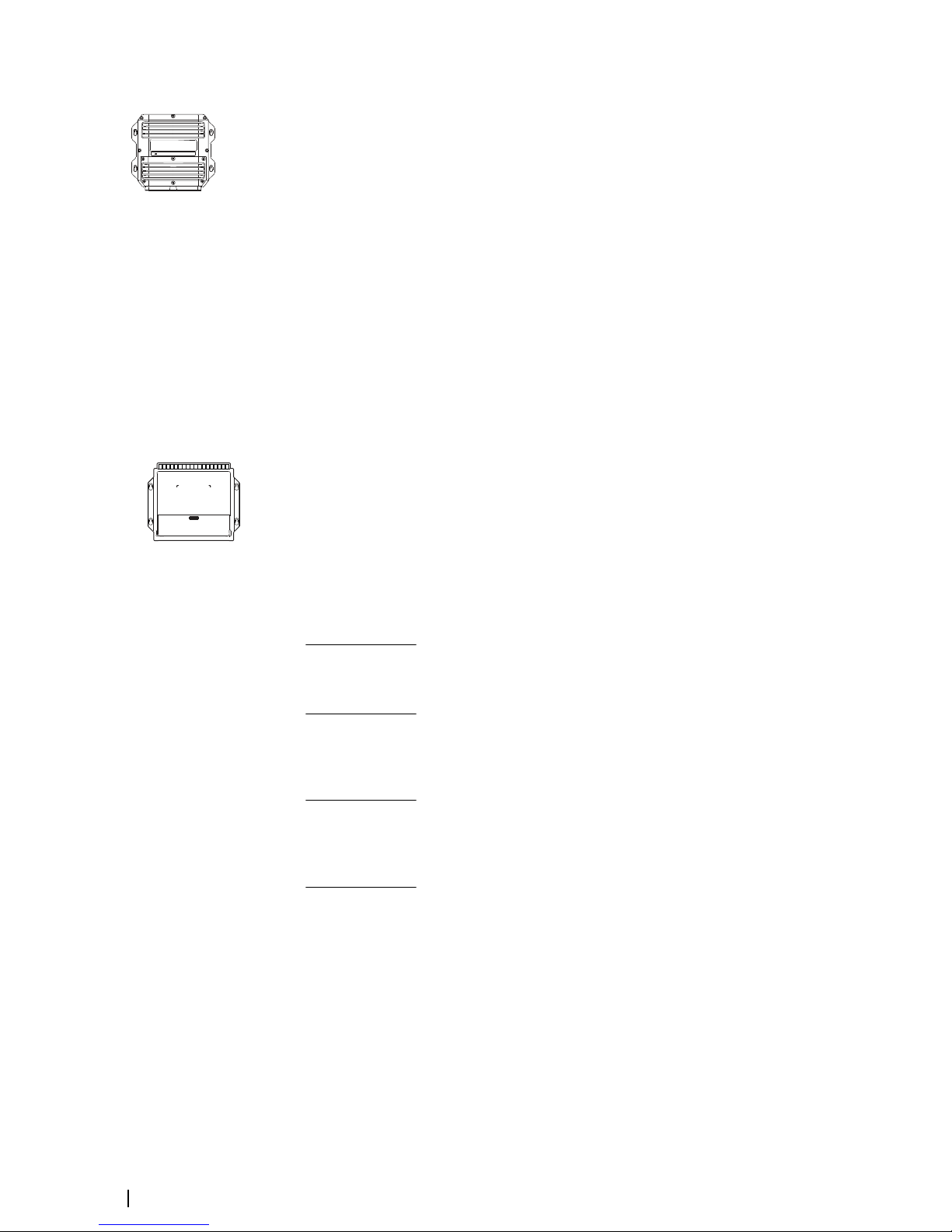
The R3000 Power supply unit
System nominal input is 24 VDC. The power supply unit converts the available 24 VDC power
source up to the transceiver's operating voltage. The transceiver input voltage is higher to
minimize the effect of voltage drop due to cable length.
Output power cables are available in 15, 30 and 65 m lengths.
The Heater kit
The optional Heater kit is used when installing the heater in the transceiver. The heater
warms up the radar transceiver to ensure safe start-up and operation. The main components
of the Heater kit are:
• the R3000 Power supply unit - provides the additional output required to drive heater
element
• the Heater upgrade kit - all the parts that are to be included in the transceiver unit
• the cable - connects the R3000 Power supply unit to the transceiver heater power
connector
Power cables for connection between R3000 Power supply unit and Heater kit are available
in 15, 30 and 65 m lengths.
SI80 Signal Interface unit
The optional SI80 Signal Interface unit is used to provide an additional IEC 61162-2 port.
Connection to the R3016 Control unit is made via NMEA 2000. The SI80 provides power and
termination for the backbone.
R3016 12U/6X manuals
The following documentation is delivered with the R3016 12U/6X Radar system:
R3016 12U/6X Operator manual (988-10911-00n)
User descriptions of the radar and of the features included in the system.
Intended audience: System operator.
R2009/R3016 Quick Guide (988-10951-00n)
Graphical document describing the keys and the main functions.
Intended audience: System operator.
R3016 12U/6X Installation and System wiring manual (988-10912-00n)
Mechanical installation and wiring, technical specifications and mechanical drawings for all
system components.
Intended audience: Shipyard installation personnel.
R3016 12U/6X Configuration and maintenance manual (988-10913-00n)
System setup/configuration, commissioning, trouble shooting, maintenance procedures,
replacement procedures for replaceable parts and spare parts listing.
Intended audience: Installation and service engineers.
R3016 Control unit Mounting template (988-10917-00n)
1:1 cut-out template with dimensions.
Ú
Note:
The last digit in the part numbers is the document's revision code. The latest
version of all documents can be downloaded from the product website on
www.navico.com/commercial.
POWER
8
Introduction | R3016 12U/6X Installation manual
Page 9
Connector layouts
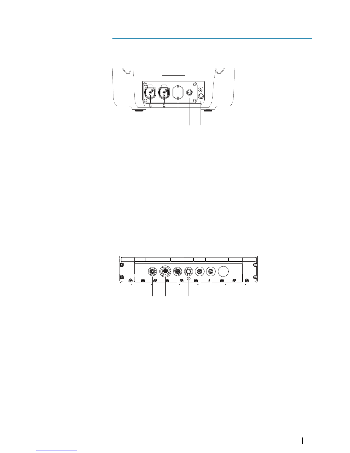
Up-mast transceiver connectors
The R3000 power supply unit converts ships 24 V to 50 V required by the up-mast transceiver.
1 2 3 4 5
1 5-pin power connector
Provides power to transceiver
2 RJ45 Ethernet socket
Provides radar and 2-way communication over a digital connection
3 Heater power connector (optional - shown not installed)
Provides power to a heater element
4 Safety switch
Used to disconnect power to transceiver circuits (excludes heater)
5 Ground terminal post
Mandatory grounding connection point for connection to vessel ground
R3016 Сontrol unit connectors
ETHERNET HDMI NMEA2000 POWER NMEA0183 NMEA0183
1 2 3 4 5 6
1 Ethernet
Radar data input and communication with transceiver
2 HDMI
Provides video output to voyage data recorder (VDR)
3 NMEA 2000
Connection for SI80 expands NMEA 0183 I/O
4 Power
24 VDC power input and system failure alarm output
5 NMEA 0183 (Serial 1)
2 x Inputs + 1 x Output
6 NMEA 0183 (Serial 2)
2 x Inputs + 1 x Output
2
Connector layouts
| R3016 12U/6X Installation manual
9
Page 10
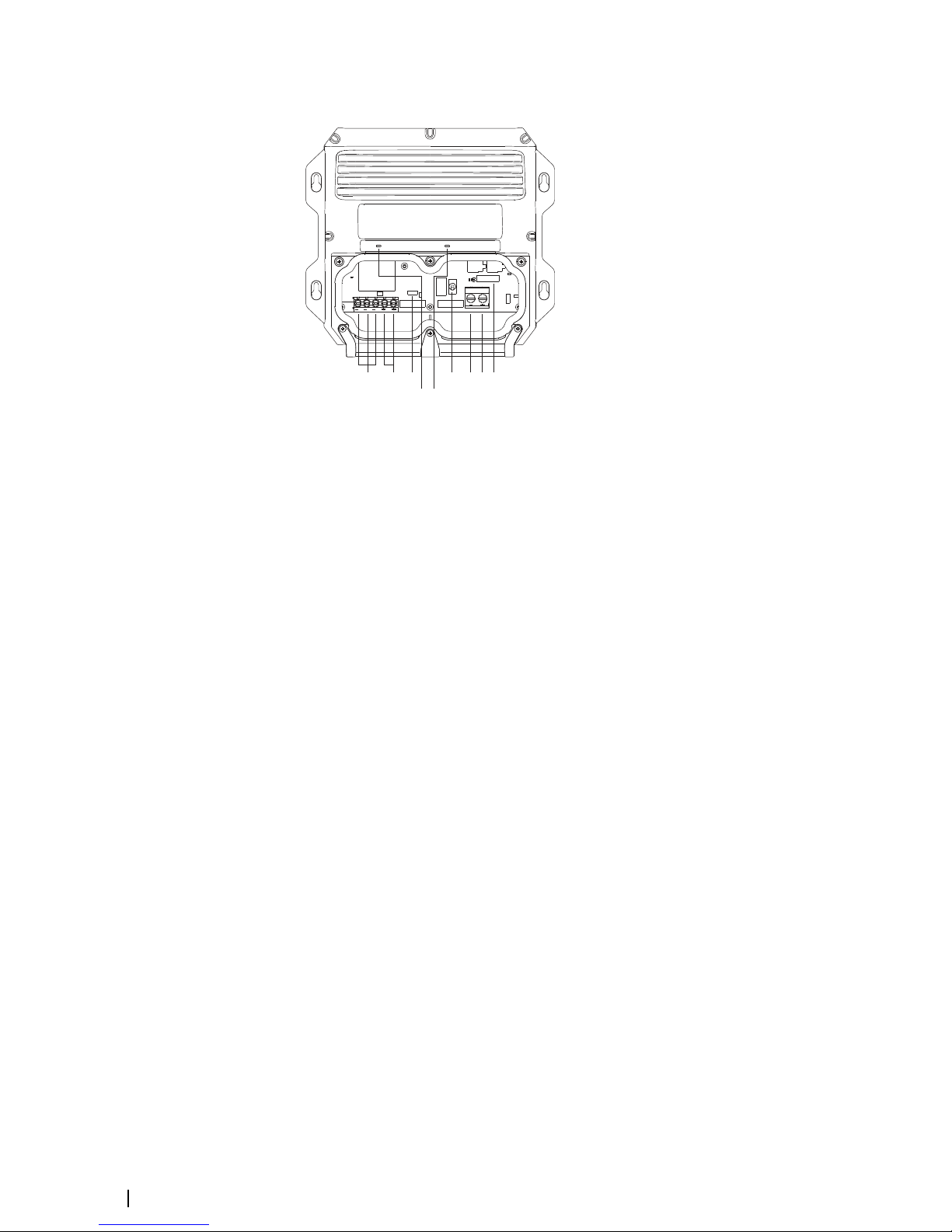
R3000 power supply unit connectors
POWER STATUS
OFF
ON
PWR OUT
PWR IN
J2
1
8 9
2 43 5 6 7
1 Negative output
Negative return to transceiver
2 Positive output
50 VDC output is used to supply transceiver or heater kit
3 J2
Power cable shield connection point
4 ON/OFF supply switch
Disables output from supply
5 Negative input
Negative return for power input
6 Positive input
24 VDC power input
7 Fuse
Protects supply from output overcurrent
8 Power LED
Indicates state of the power supply input
9 Status LED
Indicates state of power input
Ú
Note:
The drawing shows the power supply front cover removed for terminal access.
10
Connector layouts | R3016 12U/6X Installation manual
Page 11
Installation overview
The information provided by radar is of vital importance to skippers and the safe navigation
of ships. Special care should be taken to ensure correct installation of the radar, in order to
ensure the performance of the radar system is not compromised. Interference, either by
reflecting structures or other RF transmitters, may significantly impair radar performance by
creating blind sectors, clutter on the radar display or generation of false targets. All hardware
should be mounted with appropriate gauge and number of fasteners, and structure radar is
mounted to should be determined to be fit for purpose, capable of supporting the radar in
any weather or sea state.
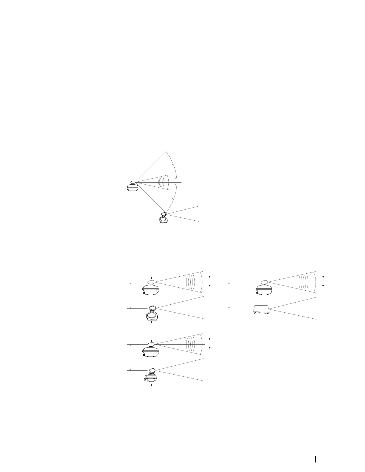
Interference
Other radar
Do not install the radar transceiver on the same beam plane as other radar – provide at least
45 degrees vertical separation. Use sector blanking as required to eliminate interference from
same frequency radar on vessel.
12.5
12.5
45
45
TX
STBY
A
B
A R3016 12U/6X radar sensor
B Other radar
The following shows suggested minimum vertical separation for different radar
combinations, where radars are installed one above the other:
STBY
2 m (6 ft)
STBY
3 m (9.8 ft)
STBY
2 m (6 ft)
12.5
12.5
TX
12.5
12.5
TX
12.5
12.5
TX
A A
A
B
C
D
A R3016 12U/6X radar sensor
B Pulse compression radar
C Broadband radar
D Other pulse radar
3
Installation overview
| R3016 12U/6X Installation manual
11
Page 12
Other RF sources
The radar antenna should be installed at a safe distance from interfering high-power energy
sources and other transmitting and receiving radio antennas.
Sensitive equipment
Some electronics such as GPS and electronic heading sensors may be particularly sensitive to
radar emissions. Follow the manufacturers guide on suitable separation distances. Avoid
having such equipment directly in the beam of the radar.
Obstructions and blind sectors
The antenna should be mounted clear of any structure that may cause signal reflections and
resultant blind sectors. Large flat metallic structures perpendicular to the radar generally
cause the worst reflections, and should be avoided.
Railings
The underside of the radar antenna should be a minimum of 50 cm above any safety rail.
Swing diameter
Ensure all obstructions are clear of the rotation of the antenna (see "Up-mast transceiver and
antennas" on page 37). To avoid the antenna coming in contact with other installed objects
while it is rotating, ensure that there is at least 200 mm between the swing circle (turning
radius) and the other installed objects.
Blind sectors
It should be kept to a minimum, and not occur in an area of the horizon from right ahead to
22.5° abaft the beam to either side. Any two blind sectors separated by 3° or less should be
treated as one combined blind sector. Individual blind sectors of more than 5°, or a total of
blind sectors of more than 20°, should not occur in the remaining area abaft the
aforementioned area. For radar installations with two radar systems, where possible, the
antennas should be placed in such a way as to minimize the blind sectors.
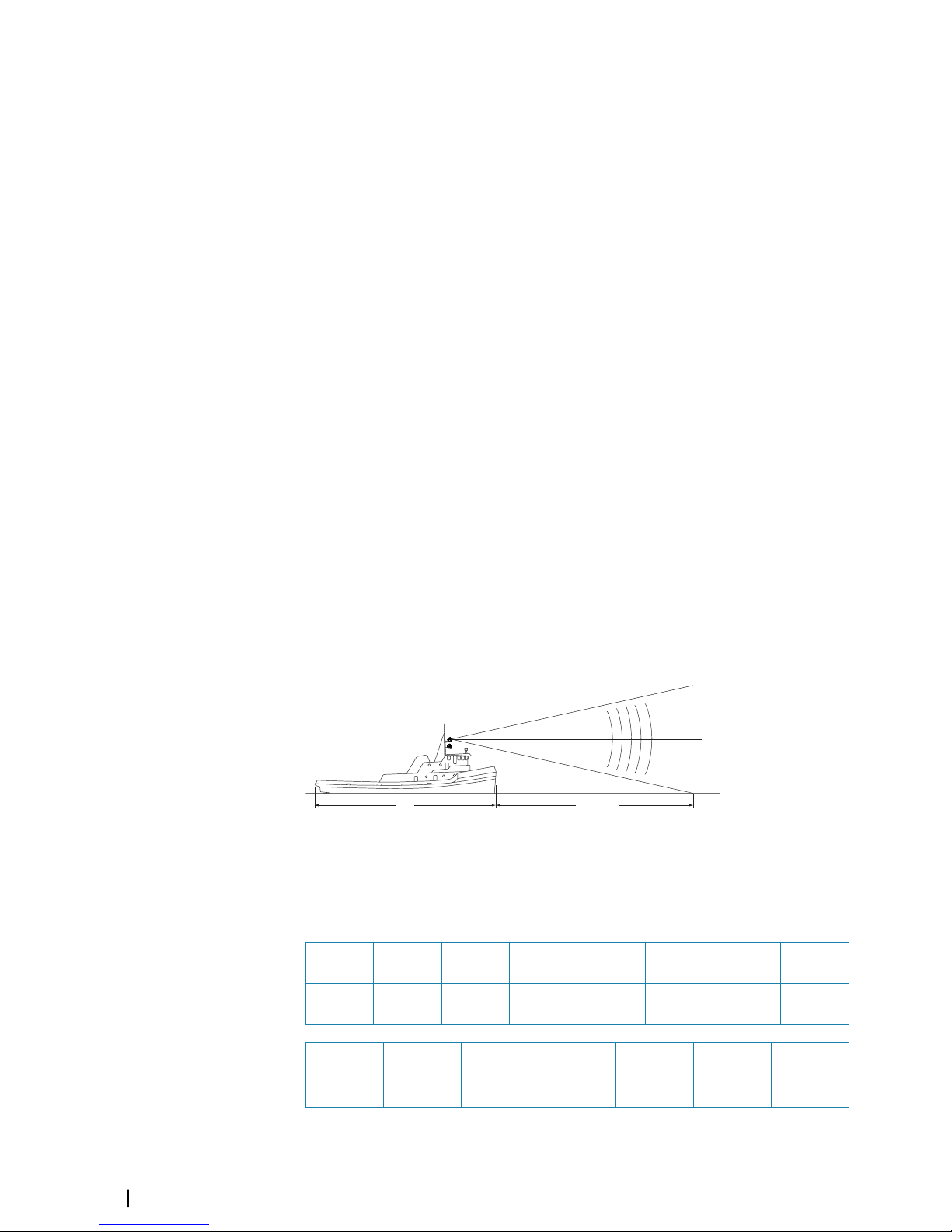
Distance to water surface
For all radar systems and where practical, a line of sight from the radar antenna to the bow of
the ship should hit the surface of the sea at no more than 500 m or twice the ship length,
depending which value is smaller. This goes for all load and trim conditions.
l
< 2l
< 500 m
Transceiver height implications
The following table indicates the effect of mounting height of antenna on the distance
before the beam hits the water.
Height
(m)
1 2 3 4 5 7.5 10
Distance
(m)
4.7 9.4 14.1 18.8 23.5 35.3 47.0
Height (m) 15 20 25 30 40 50
Distance
(m)
70.6 94.1 117.6 141.1 188.2 235.2
12
Installation overview | R3016 12U/6X Installation manual
Page 13

Height impact
The radar antenna should be located in an elevated position to permit maximum target
visibility, but no higher than necessary to achieve this as sea clutter worsens and short range
performance is compromised with increase of height. On smaller vessels excessive height
may also have a negative impact on vessel stability.
Mounting location
Up-mast transceiver
Safe service access should be provided using service platforms where necessary, having a
minimum size of 1 m2 at a suitable height and with a safety rail of suitable height.
The design of the mounting platform for the up-mast transceiver should take into account
the vibration requirements defined by IEC 60945.
The platform that is being mounted to should be level when vessel is loaded and underway
at typical cruise speed.
Ú
Note:
When working at height, ensure appropriate safety harness and lanyard is used.
Control and display
The orientation of the R3016 Control unit should be such that the user is looking ahead. The
lookout’s view should not be obscured, and any ambient light should cause minimum
degradation on the display screen in accordance with MSC/Circ.982.
Tools required
The following list covers the basic tools that are essential to installation of this system:
• Torx screwdriver, T20 (performance monitor arm)
• Philips screwdriver #1 (control unit flush mounting)
• Philips screwdriver #2 (power supply + SI80 + heater kit)
• Posi screwdriver #3 (control unit bracket fasteners)
• Combination wrench, 13 mm (antenna bolts)
• Combination wrench, 19 mm (transceiver mounting nuts)
• Hex key wrench, offset type, 6 mm (cover)
Ú
Note:
Power supply machine screw nuts are not provided. Technicians can choose the
screws and proper tools.
The following tools are not essential, but likely to be required:
• Jigsaw (wood and metal blades) (cut-out for controller flush mounting)
• Router + bits (cut-out for controller flush mounting)
• Cordless drill
• Drill bit set
• 16 mm drill bit (needed for NMEA 2000 plugs)
Ú
Note:
In case the heater system is included, additional tools are required. Refer to "Tools
required" on page 18.
Installation overview
| R3016 12U/6X Installation manual
13
Page 14

Hardware mounting
Install the up-mast transceiver
The up-mast transceiver must be mounted with the cable connectors pointed aft. Ensure
there is adequate space for the housing to open fully backwards. There should also be
sufficient space behind the up-mast transceiver in order to easily access the plugs and safety
switch at back of housing.
524 mm (20.6”)
458 mm (18.0”)
696 mm (27.4”)
465 mm (18.3”)
346 mm
(13.6”)
178 mm (7.0”)
>141mm (7.4”)
93 mm (3.7”)
>200 mm
(7.9”)
634 mm (25”)
Securely mount the up-mast transceiver prior to fitting the antenna.
Ú
Note:
The waveguide protection cover on the up-mast transceiver must not be removed
until immediately prior to antenna fitment.
Ú
Note:
While the up-mast transceiver is fitted with mounting studs to cater for common
installation scenarios, it may be required to fit different studs or bolts to suit the specific
requirements of the installation. The supplied studs are M12, and allow mounting to a
surface no more than 30mm thick. Any replacement hardware should allow for a woundin depth of at least 2x the diameter of the bolt or stud (e.g. >24mm). Use a good quality
isolating or anti-seize compound on the thread, to prevent electrolysis.
Fasteners should be of 316L stainless and property class 70 or better (bolt heads will be
marked accordingly), or similar strength high tensile steel with a permanent protective
coating system applied.
4
14
Hardware mounting | R3016 12U/6X Installation manual
Page 15

Fitting the performance monitor arm
Attach the PM arm to the up-mast transceiver housing using the supplied T20 fasteners. The
arm should be oriented to point upwards. Ensure the gasket ring is fitted between the
housing and the base of the arm.
All electrical connections are made when the performance arm is attached to the up-mast
transceiver – it is not necessary to complete any further connections inside the up-mast
transceiver enclosure.
Fitting the control unit
The control unit may be mounted using either the supplied dash top bracket, or flush
mounted in to the ships control console. A suitable position will not obscure the view out of
the bridge windows, and will be oriented to minimize direct sunlight reflection off the
screen. The screen should be mounted no more than 0.75m from either the standing or
seated position of the operator. All keypad controls must be easily accessible.
U-bracket mounting
1. Place the bracket in the desired mounting location. Ensure that the chosen location has
enough height to accommodate the unit fitted in the bracket, and allows tilting of the
unit. Also adequate space is required on both sides to allow tightening and loosening of
the knobs.
2. Mark the screw locations using the bracket as a template, and drill pilot holes. Use
fasteners suited to the mounting surface material. If the material is too thin for selftappers, reinforce it, or mount the bracket with machine screws and large washers. Use
only 304 or 316 stainless steel fasteners.
3. Screw down the bracket.
4. Using the screws provided in the gimbal kit, fasten the gimbals to the unit.
5. Mount the unit to the bracket using the knobs. Hand tighten only. The ratchet teeth in the
bracket and display case ensure a positive grip and prevent the unit changing from the
desired angle.
6. Fix the bracket straps.
Hardware mounting | R3016 12U/6X Installation manual
15
Page 16

4
65
3
Panel mounting
The screws and gasket used for panel mounting are included in the box. For mounting
instructions, refer to the Panel mounting template.
Install the R3000 power supply unit
The power supply should ideally be installed in an area that is dry, cool, and free of excessive
vibration.
Cooling requirements
The power supply must be installed in an area that offers sufficient cooling, and that is not
subject to temperatures is excess of 55 °C. Ideally the area should be actively ventilated to
ensure a consistent operating temperature. The power supply must be installed on a vertical
surface, with the cables exiting downwards. Where area of installation is poorly ventilated,
provide space around all sides of the power supply, per the following diagram;
16
Hardware mounting | R3016 12U/6X Installation manual
Page 17

POWER STATUS
500 mm
500 mm
200 mm200 mm
Grounding wire
The R3000 power supply unit has a chassis ground terminal on the underside of the case. The
chassis ground is DC isolated from power to eliminate the risk of electrolytic corrosion.
It is recommended that the power supply unit ground is connected to the vessels bonded
ground or a non-bonded RF ground at the closest possible location, using 12 AWG wire (or
thicker):
Fastening in place
The power supply unit is supplied with different fasteners to suit most mounting materials.
Self-tapping wood screws with washers and nuts (x4) for wood, fiberglass, or soft plastics,
and machine screws (x4) for harder surfaces such as aluminum, and those too thin for selftapping screws. The self-tapping screws are 6G x 45mm (1.75”), so will extend in to mounting
surface approximately 30mm (1.2”). The machine screws are 60mm (2.4”)”, so mounting
surface should be no more than 40mm (1.6”) thick.
Drill bit sizes for the self-tappers and machine screws are 2.5mm and 4.5mm respectively.
Hardware mounting
| R3016 12U/6X Installation manual
17
Page 18

Adding the heater system (optional)
An optional heater can be installed to ensure transceiver reliable operation down to -40 °C.
The heater kit consists of an R3000 power supply, and the heater components and fasteners
for inside the transceiver. The heater power cable must be ordered separately in a length
suited to the installation. The power cable is the same type as used for powering the
transceiver.
Heater kit parts
1
2
3
4
5
6
7
8
1 Heater element
2 Connector (female) for temperature sensor
3 In-line fuse holder (10 A SB fuse)
4 External waterproof socket
5 Thermo-conductive gel
6 Temperature sensor
7 2 x hex pan screws M4
8 2 x hex pan head screws M3
Tools required
The following list covers the basic tools that are essential to installation the heater kit:
• Screwdriver Torx - T20
• Screwdriver Torx - T10
• Hex key – 6 mm
Install the heater R3000 power supply unit
As the heater power supply housing is identical to the transceiver power supply unit, use the
"Install the R3000 power supply unit" on page 16 for instructions.
18
Hardware mounting | R3016 12U/6X Installation manual
Page 19

Install heater kit in transceiver housing
Ensure the radar system is shut down, and a warning sign has been placed at the controller.
When at the up-mast transceiver set the safety switch in the (power) OFF position.
Remove the two pan head screws securing the blanking plate found between the Ethernet
port and the safety switch on the rear of the up-mast transceiver.
Pass the heater elements, spade connectors, and fuse holder through the hole, from outside
to the inside.
Secure the plug body to the transceiver housing with existing fasteners.
Inside the up-mast transceiver identify the temperature sensor and heater element
mounting locations by referring to the following diagram. Route the Heater kit loom along
the dotted line shown. Ensure no part of the cable has enough slack to risk coming in to
contact with moving parts like the main gear wheel.
Secure the temperature sensor with two supplied M3 pan head screws, and slide on the blue
spade connectors. Insert the heater elements into the mounting holes and secure them in
place using supplied M4 pan head screws.
Hardware mounting
| R3016 12U/6X Installation manual
19
Page 20

1
2
3
4
5
6
7
8
1 Temperature sensor mounting screw holes
Pan head screws are inserted here to retain the sensor
2 Lower heater element mounting hole
Lower element is directly inserted into this hole
3 Lower heater element retaining screw hole
Pan head screw is inserted here to retain the element
4 Upper heater element mounting hole
Upper element is directly inserted into this hole
5 Upper heater element retaining screw hole
Pan head screw is inserted here to retain the element
6 PCB mounted cable clip
Pass a heater loom through this clip
7 Mounting foot
Cable a tie loom to this point
8 Heater loom route
Follows a route of existing cables. Ensure the loom is secured to the existing loom
at regular intervals using cable ties. Pass the loom through any cable clip that is
used to support existing cables.
20
Hardware mounting | R3016 12U/6X Installation manual
Page 21

Install the SI80
The SI80 is delivered with an Installation Guide (SI80_IG_988-10475-00n). See the guide for
installation instructions.
Hardware mounting
| R3016 12U/6X Installation manual
21
Page 22

Wiring
General precautions
•
Check all ground connections. During the hardware installation they must be completed
before power and communication cabling.
• Create drips loops where cable connects to product, to prevent water collecting on
device connectors.
• Cables should be kept as short as possible, to minimize chance of interference and voltage
drop.
• All cables between antenna and radar system units should be routed as directly as
possible, consistent with consideration for other equipment, in order to reduce
electromagnetic interference effects.
• Cables should not be installed close to high-power or high frequency conducting cables,
such as radar or radio-transmitter lines, large DC motor cables.
• Where cables intersect, try to stay at right angles (90°) to minimize inductance of noise.
• Only use suitable waterproof connectors when joining cables.
• If a cable being pulled through a concealed area requires excessive force to finish pulling
through the remaining cable, consider rerouting cable via an alternative route – otherwise
cable conductors may get broken, the cable sheath & insulation may be damaged, or the
same damage may be done to adjacent cables, which may cause a fire.
System overview diagram
GYROBAM
AISEPFS
TRACK
DATA
READER
SDME
VDR
ETHERNET HDMI NMEA2000 POWER NMEA0183 NMEA0183
POWER
STATUS
POWER
STATUS
Up-mast transceiver cables
It is advised to run the cables starting at the up-mast transceiver location, working towards
the power supply and control unit console:
• Gravity feeding of cables in radar tower conduit is naturally easier, especially where no
draw wire is available.
• The Ethernet plug is smaller at console end: 20mm plug diameter vs 36 mm plug.
• The power cable is un-terminated at the POWER SUPPLY end, whereas up-mast
transceiver end has 36 mm plug.
Ú
Note:
Minimum bend radius of the Ethernet cable is 100 mm. Do not subject the cable
to tighter bends, as distortion of the cable can degrade the cables performance, and at
worst may break conductors due to fatigue.
5
22
Wiring | R3016 12U/6X Installation manual
Page 23

Up-mast transceiver grounding
Connect a tinned copper cable (>25 mm2) between the ground terminal on the up-mast
transceiver and the radar mast, using crimped or soldered ring terminals at either end. Cable
should be kept to minimum necessary length. Ensure it is fastened using a suitable stainless
bolt and lock nut or spring washer. Self-tapping screws should not be used. Good electrical
connection is essential - ensure paint or other isolating coatings on surface are properly
removed around area of bolt and ring terminal contact with mast. After fitting, apply a
suitable anti-corrosive coating to the assembly.
Ú
Note:
Radar mast should be a good conductor (i.e. metal), and be bonded to rest of
ships ground. If not, earth cable should be run to nearest grounded structure.
Ú
Note:
Earth strap is ideally braided tinned copper, but tinned power cable is also
suitable.
Connection at the up-mast transceiver
The plugs for Ethernet and power should only be connected when the earth strap is already
in place.
Before inserting plugs, ensure the safety switch is set to the OFF position as marked on
switch.
All three connectors are keyed, so plug orientation cannot be done incorrectly. Ensure the
retainer clip is fully engaged after insertion.
1
2
3
4
1 Retention clip
Wiring | R3016 12U/6X Installation manual
23
Page 24

2 Power plug (5-pin in armored housing)
3 Ethernet plug (RJ45 in armored housing)
4 Earth strap
Ú
Note:
Coil the Ethernet cable to form two loops, and clip on the supplied ferrite choke.
With two loops the cable will pass through the ferrite three times. The loops should be
made within about 10cm of the LAN plug inserted in to the transceiver housing. Do not
make the loops too tight as this could damage the cable.
Transceiver power supply connection
The power supply converts ship's 24 V to 52 V required by the up-mast transceiver.
Two R3000 power supplies are required for installations utilizing a heater kit. One of the
power supplies is used to drive the transceiver, the other powers the heater.
To access the electrical terminals on the power supply, remove the front cover by undoing
the six Philips screws on the front of the unit. Lift off the cover, and pull forward the wshaped plastic gasket retainer. Pull out the rubber gaskets.
When running cables in to the supply, ensure they pass through the gasket first.
The ship's 24 V DC supply should be connected using appropriate sized cabling to support
the maximum current draw (approx. 15 - 20 A under max wind load) without significant
voltage drop. It is recommended a minimum of 10mm2 (8 AWG) cable is used when doing
short runs. The terminals will accept up to 25mm2 (4 AWG) cable.
+
-
2
3
1
4
5
7
6
POWER STATUS
OFF
ON
PWR OUT
PWR IN
POWER STATUS
OFF
ON
PWR OUT
PWR IN
24
Wiring | R3016 12U/6X Installation manual
Page 25

1 Transceiver power cable (15 m in the example)
2 Ethernet cable
3 Heater power cable (15 m in the example)
4 Transceiver
5 R3000 power supply
6 Fused supply (30 A fuse for each supply with normal action, able to cut 32 VDC)
7 Ship's 24 VDC supply
The longer 30 m and 65 m cables have additional cores which require connection to the
extra screw terminals, per the diagram below.
PWR OUT
PWR OUT
1 2 3
PWR OUT
1 Wired with 15 m cable
2 Wired with 30 m cable
3 Wired with 65 m cable
Power supply diagnostics
There are two LEDs on the front cover of the R3000 power supply unit. They provide basic
diagnostic information on the connections: wiring and power supply connection status.
The following table covers the various possible sequences.
LED Color Pattern Meaning
STATUS Green On constant Output voltage (52 VDC) is
available to the transceiver
POWER Green On constant Input supply is good, voltage is
within acceptable range
OFF N/A No supply, or protection fuse is
blown
Red On constant • R3000 switch set to OFF
• Output overload
• Input voltage too high (>45 V
DC)
• Input voltage too low (<17 V DC)
• Output voltage too high (>60V)
• Temperature too high (>125° C)
Red Blinking Output overload
Ú
Note:
The power supply has an initialization sequence at startup, and will momentarily
illuminate the red LED, this is normal behavior.
Control unit power and alarm output connection
The R3016 Control unit power cable has four wires, two of which provide power to the unit,
and two for the alarm output.
Wiring | R3016 12U/6X Installation manual
25
Page 26

1
2
3
4
5
6
7
+
-
ETHERNET
HDMI
NMEA2000
POWER
NMEA0183
NMEA0183
1 Alert management system
2 Blue wire – alarm output (N/C isolated contact)
3 Yellow wire – alarm output negative return
4 Red wire - positive DC supply (24 VDC system)
5 Black wire - negative DC supply (24 VDC system)
6 Fuse - see table at end of section
7 DC supply
Connection of Ethernet cable to control unit
The Ethernet cable is pre-terminated and is simply plugged directly to the R3016 Control
unit's NETWORK connector. Under no circumstance should this cable be plugged into a
network hub or any other Ethernet device.
Ú
Note:
Direct connection must be made between the transceiver and controller. Failure
to do so would make the system non-compliant.
Sensor connection
Any sensor connected to the R3016 12U/6X system should meet IMO performance standards
and be certified. Failure to do so would make the rest of the system non-compliant.
The R3016 control unit supports up to 4 inputs and 2 outputs for sensors. Expansion beyond
the supplied 4 inputs and 2 outputs can be achieved by the addition of an SI80 through
connection to the control unit’s NMEA 2000 port.
All inputs and outputs can be configured to match the speed of the connected sensors.
Sensor connection overview diagram
The diagrams below show the configuration of a system with 5 inputs using the SI80 for
expansion, as well as a system only using the 4 on-board inputs.
26
Wiring | R3016 12U/6X Installation manual
Page 27

GYROBAM
AISEPFS
TRACK
DATA
READER
SDME
ETHERNET
HDMI
NMEA2000
POWER
NMEA0183
NMEA0183
Configuration with BAM
GYRO
SDME
AISEPFS
TRACK
DATA
READER
ETHERNET HDMI NMEA2000 POWER NMEA0183 NMEA0183
Configuration without BAM
R3016 12U/6X must be connected to an External Position Fixing System (EPFS), a gyrocompass/heading sensor, and a SDME source via serial line.
Ground stabilization requires an external sensor signal capable of providing an input and an
indication of own ship’s speed over ground, for example from an EPFS, SDME or use of
stationary tracked reference targets. If a ground-referenced speed log is used for ground
stabilization, it must be of dual axis type.
Connections to a BAM device is mandatory if these devices are available on a vessel.
Ú
Note:
The gyro-compass or heading sensor must have an update rate that is adequate
for the ship’s rate of turn – the performance should meet or exceed the relevant
standards adopted by the IMO (IMO A.424(XI), A.821(19) and MSC.116(73)).
Ú
Note:
Analog sensors are not supported on the R3016 12U/6X radar system.
Ú
Note:
If more than four inputs are required (i.e. when BAM is connected), an SI80 will
need to be connected to provide additional NMEA 0183 ports. Refer to"SI80 connection" on
page 29 for details.
Serial ports – color code
The NMEA 0183 labelled ports on the back of the control unit provide four inputs (Listeners)
and two outputs (Talkers) for the various IEC 61162 interfaced sensors, including gyro/
heading, speed log, EPFS, SDME, etc.
Wiring
| R3016 12U/6X Installation manual
27
Page 28

1
2
5
63
4
ETHERNET
HDMI
NMEA2000 POWER
NMEA0183
NMEA0183
Key Description Key Description
1 Port 1 Listener
(twisted pair with screen and
drain)
4 Port 3 Listener
(twisted pair with screen and
drain)
2 Port 2 Listener
(twisted pair with screen and
drain)
5 Port 4 Listener
(twisted pair with screen and
drain)
3 Port 1 Talker
(1A and 1B twisted pair)
6 Port 3 Talker
(1A and 1B twisted pair)
Ú
Note:
The serial cables supplied are identical.
Ú
Note:
The wiring of sensors which are connected to inputs should be recorded for
reference as is required when commissioning the system.
1
2
6
7
8
3
4
5
1
2
6
7
3
4
5
8
Unit socket Cable plug
Key Port (left
socket)
Port (right
socket)
Purpose Color
Shield Drain
1 Port 2 Port 4 Listener B (Rx+) Green
2 Port 2 Port 4 Listener A (Rx-) Yellow
3 Port 1 Port 3 Shield Drain
4 Port 1 Port 3 Common Black
5 Port 1 Port 3 Talker B (Tx+) Brown
6 Port 1 Port 3 Talker A (Tx-) White
Shield Drain
7 Port 1 Port 3 Listener A (Rx-) Green
8 Port 1 Port 3 Listener B (Rx+) Yellow
28
Wiring | R3016 12U/6X Installation manual
Page 29

SI80 connection
The SI80 is connected when a fifth serial port is required. The device is connected to the
control unit via NMEA 2000, using Micro-C cables. The NMEA 2000 network must be powered
and be terminated at both ends.
1
5
2
8
6
4
9
3
+
-
T
T
ETHERNET HDMI NMEA2000 POWER NMEA0183 NMEA0183
7
1 SI80 (connected as end-of-line device on network due to internal terminator)
2 Terminator (on-board selectable)
3 SI80 power cable
4 Fuse
5 DC supply (+24 V DC)
6 Micro-C drop cable (must be <6’, not included)
7 Micro-C backbone (bare ends at SI80)
8 Micro-C T-piece
9 Micro-C terminator plug (not included)
Refer to Installation Guide supplied with the SI80 for further details, including alternative
NMEA 2000 connection, as well as NMEA 0183 input wiring.
Ú
Note:
Refer to "Accessories" on page 36 for a list of cables available.
Ú
Note:
The SI80 should only be used to connect to the SDME or heading source. Never
connect the BAM system via the SI80.
Ú
Note:
Do not connect more than one sensor via the SI80. This would make the system
non-compliant.
VDR connection
An HDMI video output is provided for interface to a 3rd party Voyage Data Recorder (VDR).
The output mirrors the screen display, and is at the same resolution. The VDR connected to
should accept digital video input, either using DVI or HDMI interface.
Wiring
| R3016 12U/6X Installation manual
29
Page 30

VDR
1
3
2
ETHERNET
HDMI
NMEA2000
POWER
NMEA0183
NMEA0183
1 Voyage Data Recorder with DVI input
2 DVI connectors
3 DVI – HDMI adaptor cable
Ú
Note:
It is not possible for the user to deactivate video output to the VDR port.
30
Wiring | R3016 12U/6X Installation manual
Page 31

Technical specifications
For updated technical specifications, compliance and certifications, refer to the product
website.
General
Description
12 kW X-band pulse radar IMO class 3 with 6
ft end-fed slotted waveguide antenna
Standards • IMO-Resolution A.278 (VIII), A.694 (17), A.
823 (19), MSC 191 (79), MSC 192 (79)
• EN 62388 Ed.2.0, 2014
• EN 62288 Ed.2.0, 2014
• EN 60945 Ed.4.0, 2002 incl. Corr.1, 2008
• EN 61162-1 Ed.4.0, 2010
• EN 61162-2 Ed.1.0, 1999
Type approval Maritime Equipment Directive 96/98/EC, 4.36
Radar Equipment CAT 3
Environmental
Temperature
Operating temperature, protected unit -15°C to 55°C (According to IEC 60945 ed.4.0)
Operating temperature, exposed unit
-25°C to 55°C (According to IEC 60945 ed.
4.0)
Operating temperature, exposed unit
(heater kit fitted)
-40°C to 55°C according to RMRS rules
(2-020101-040-E Vol 2 - Environmental Test
of Equipment)
Storage temperature, exposed unit -25°C to 70°C (According to IEC 60945 ed.
4.0)
Storage temperature, exposed unit
(heater kit fitted)
-60°C to 70°C according to RMRS rules
(2-020101-040-E Vol 2 - Environmental Test
of Equipment)
Damp heat +40°C, 93 % relative humidity 1 cycle
(According to IEC 60945 eg. 4.0)
Vibration According to IEC60945 ed. 4.0
Shock
According to RMRS rules (2-020101-040-E
Vol 2 - Environmental Test of Equipment)
IP class
R3016 Control unit IP66
Scanner IP66
Power supply units IP65
Relative wind velocity
100 knots wind tunnel test at 20 RPM
(According to IEC 62388)
Power
Transceiver up-mast unit
Supply voltage (V DC) 50
Average power (W) 250. (Additional 300W if heater kit is
included)
R3016 Control unit
Supply voltage (V DC) 24
6
Technical specifications
| R3016 12U/6X Installation manual
31
Page 32

Power
Average power (W) 20
R3000 Power supply unit
Supply voltage (V DC) 24
Max power (W) 300
330 when used for Heater kit
Fuse Rating (A) 30
Heater kit
Warm-up time from cold start-up
at -40 °C
(heater kit fitted)
3 hours
Fuse rating (for heater loom in transceiver)
(A)
10
Physical
Dimensions Refer to Dimensional drawings
Antenna swing circle diameter (cm) 183 cm (6 feet)
Weight
Pedestal + Antenna (Kg) 40 (35 kg transceiver + 5 kg antenna)
R3016 Control unit (Kg) 4
Power Supply Unit (Kg) 1
Heater loom & connector Trivial
Performance
RPM 20 or 36 (selectable)
Nominal peak power (KW) 12
Operating frequency (MHz) 9410
Pulse length (ns)
Short pulse 75
Medium pulse 300
Long pulse 825
PRF (Hz)
Short pulse 3000
Medium pulse 1500
Long pulse 750
Modulator MOSFET Solid State
IF amplifier Logarithmic
IF dynamic (dB) 95
IF center frequency (MHz) 60
IF bandwidth (MHz)
Short pulse 24
Medium pulse 4.8
Long pulse 1.8
Horizontal Beam width (deg.) 1.35
Vertical Beam width (deg.) 22
VSWR < 1.20
32
Technical specifications | R3016 12U/6X Installation manual
Page 33

Performance
Overall noise figure (nominal dB) < 5
MDS on long pulse (dBm) -105
Display features
Presentation mode Day or Night
Typical viewing distance (m) 0.75
Resolution (pixels) 1366x768
Aspect ratio 16:9
PPI Diameter (mm) >180
Short range
Available scales (NM) 1/8, 1/4, 1/2, 3/4, 1.5 and 3
Range video resolution (m) 11.25
Azimuth on-screen resolution (Deg) 0.1
Medium range
Available scales (NM) 6 and 12
Range video resolution (m) 45
Azimuth on-screen resolution (Deg) 0.1
Long range
Available scales (NM) 24, 36, 48, 64, 72
Range video resolution (m) 125
Azimuth on-screen resolution (Deg) 0.1
Relative Motion (RM) Head Up, Course Up and North Up
True Motion (TM) Course Up and North Up
Off-centering Up to 75% of range scale in use
Cursor
Polar and Geographical coordinates,
continuously displayed when cursor is
activated
I/O interface
Data inputs
Serials 2 x IEC 61162-1
2 x IEC 61162-2
1 x IEC 61162-1 using SI80 (optional)
Radar Video Input 1 x Ethernet 100Mbs
Data outputs
Serials 2 x IEC 61162-1
Alarm output
1 x Isolated pair normally closed radar failure
contact
Micro-C connector
SI80 connection for IEC 61162-1 expansion
(to be used with Speed Log sensor, when
BAM is present)
VDR
HDMI output, same resolution as radar
display
Target tracking
Acquisition Manual, up to 20 targets
Technical specifications | R3016 12U/6X Installation manual
33
Page 34

Target tracking
Tracking Automatic, up to 20 targets
AIS
Presentation
Totally 120 target capacity, of which a
maximum of 20 can be activated.
AIS overflow mechanism of priority
Safe checking 120 targets in total
Mapping
Map drawing
Operator compiled maps
Up to 32 maps, each may contain up to 120
segments and 32 symbols
Selectable colors and line styles
Map stabilization
Relative
Geographic
Map storage
By name
Built-In non-volatile memory used
SD Card transfer available
Map adjustments Translation and rotation allowed
Parallel Index Four independent parallel index lines
Data readout
Own ship data
Target tracking data
AIS target data
Compass safe distance
Safe distance to the
standard magnetic
compass
Safe distance to the
steering magnetic
compass
R3016 Control unit 0.65 m 0.43 m
12 kW X-Band SRT
transceiver
1.43 m 0.87 m
R3000 Power supply unit 0.3 m 0.24 m
34
Technical specifications | R3016 12U/6X Installation manual
Page 35

Spare parts
For updated technical specifications, compliance, and certifications refer to the product
website.
Part number Description Note
000-10668-001 Performance monitor (PM) arm
000-13252-001 SRT LAN electronic assembly
000-10675-001 RF detector assembly with LNFE
000-10680-001 Noise diode
000-10683-001 Motor
000-10682-001 SRT gear reducer
SP-305274A1-001 Performance monitor diode
000-10678-001 Duplexer circulator
000-10679-001 Limiter
000-10684-001 Brushless controller assembly
000-10681-001 Bearing reader PCB
000-10671-001 SRT power PCB
000-10672-001 SRT MOS PCB
000-10674-001 SRT control PCB
000-13253-001 Magnetron
000-12393-001 Serial cable high speed NMEA 0183 8 way
(2 m)
Serial cable
000-12399-001 Front case service pack R3016 Bonded touch screen
replacement
000-12401-001 Keypad reader kit R3016 Keypad PCB and
buttons replacement
000-12408-001 SD door kit R3016 Card reader door and
gasket replacement
000-12410-001 Dash mounting kit R3016
000-12412-001 Bracket mounting pack R3016
000-12414-001 Suncover R3016
000-12520-001 Bezel assembly edge R3016
7
Spare parts
| R3016 12U/6X Installation manual
35
Page 36

Accessories
Part number Description Note
000-12387-001 Power cable (15 m) For transceiver or
heater use
000-12388-001 Power cable (30 m) For transceiver or
heater use
000-12389-001 Power cable (65 m) For transceiver or
heater use
000-12390-001 Ethernet cable (15 m) For transceiver or
heater use
000-12391-001 Ethernet cable (30 m) For transceiver or
heater use
000-12392-001 Ethernet cable (65 m) For transceiver or
heater use
000-12427-001 HDMI DVI cable (1.5 m)
000-10425-001 SI80 SIMRAD signal interface
000-0127-52 TR-120-KIT NMEA 2000
terminator kit
000-0119-88 Micro-C cable (0.6 m) NMEA 2000 cable
000-0127-53 Micro-C cable (1.8 m) NMEA 2000 cable
000-12386-001 Heater upgrade kit for SRT LAN Requires separate
power cable
8
36
Accessories | R3016 12U/6X Installation manual
Page 37

Dimensional drawings
Up-mast transceiver and antennas
1800mm (70.8”)
200mm (7.9”)
364mm (14.3”)
524mm (20.6”)
458mm (18.0”)
466 mm (18.3”)
696 mm (27.4”)
200mm (7.9”)
146mm (5.7”) 178mm (7.0”)
R3000 Power supply unit
213.0 mm (8.39")
195.0 mm (7.68")
92.5 mm (3.64")
196.5 mm (7.74")
82.7 mm (3.26")
86.2 mm (3.39")
POWER
STATUS
9
Dimensional drawings
| R3016 12U/6X Installation manual
37
Page 38

R3016 Control unit
+
_
455 mm (17.91”)
477 mm (18.77”)
505 mm (19.88”)
280 mm (11.02”)
120 mm (4.72”)
67 mm
(2.63”)
SI80 Signal Interface unit
211 mm (8.29")
197 mm (7.77")
185 mm (7.27")
60 mm
(2.36")
180 mm
(7.08")
80 mm
(3.15")
48 mm
(1.88")
Antenna rotating diameter
1830 mm (72.05”)
38
Dimensional drawings | R3016 12U/6X Installation manual
Page 39

Technical drawings
The System block diagram (992-21511-01A-R3016) is enclosed.
System block diagram
000-10425-001
SI80 SIMRAD SIGNAL INTERFACE
(refer to SI80 Installation Guide)
SPEED LOG (IEC 61162-1)
(Only if BAM is present)
SERIAL EXPANSION - OPTIONAL
AIS (IEC 61162-2)
EPFS (IEC 61162-1)
BAM (IEC 61162-1)
(if present, else SPEED LOG)
GYRO (IEC 61162-2)
TERMINATION KIT
000-0127-52
PREWIRED
000-0119-88 (0.61 m) OR
000-0127-53 (1.82 m)
RADAR FAIL ALARM CONTACT
VDR (DVI)
PREWIRED
000-00128-001 (2 m)
PREWIRED
000-12427-001 (1.5 m)
PREWIRED
000-12390-001 (15 m) OR
000-12391-001 (30 m) OR
000-12392-001 (65 m)
PREWIRED
2 x 000-12393-001 (2 m)
000-12188-001
R3016, RADAR DISPLAY 16”
NOTES:
- CABLES PREWIRED OR WITH P/N ARE SUPPLIED BY NAVICO
24 VDC
FROM SHIPS EMG. SUPPLY
24 VDC
FROM SHIPS EMG. SUPPLY
24 VDC 320W
FROM SHIPS EMG. SUPPLY
24 VDC 320W
FROM SHIPS EMG. SUPPLY
PREWIRED
000-12387-001 (15 m) OR
000-12388-001 (30 m) OR
000-12389-001 (65 m)
PREWIRED
000-12387-001 (15 m) OR
000-12388-001 (30 m) OR
000-12389-001 (65 m)
000-12384-001
R3000 POWER SUPPLY UNIT
000-12384-001
R3000 POWER SUPPLY UNIT
HEATER KIT - OPTIONAL
OUTDOOR
INDOOR
SAFETY
SWITCH
6 Ft Antenna and Pedestal with 12 kW Transceiver Up Mast, Digital Video
000-12383-001 + 000-10324-001
10
Technical drawings
| R3016 12U/6X Installation manual
39
Page 40

*988-10912-001*
www.navico.com/commercial
 Loading...