

Page 1

MANUAL
SIMRAD QS50
Quick Stick
20222246A Sw.1.1 English
Page 2

Simrad QS50 Quick Stick
2 20222246 / Rev. A
About this document
Rev Date Written by Checked by Approved by
09.05.06 NG NS ThH Rev. A
First edition
© 2006 Simrad AS. All rights reserved.
No part of this work covered by the copyright hereon may be reproduced or
otherwise copied without prior permission from Simrad AS.
The information contained in this document is subject to change without prior
notice. Simrad AS shall not be liable for errors contained herein, or for incidental
or consequential damages in connection with the furnishing, performance, or use
of this document.
Page 3

Introduction
20222246 / Rev. A 3
Contents
1 SYSTEM DESCRIPTION...............................................5
1.1 General..................................................................................................5
1.2 How to use this manual.........................................................................5
2 OPERATION................................................................6
2.1 Power On/Off........................................................................................7
2.2 Activating the QS50..............................................................................7
2.3 Mode Selection .....................................................................................7
2.4 Thruster Function..................................................................................9
2.5 Lock Function.....................................................................................10
2.6 Illumination.........................................................................................11
2.7 Alarms.................................................................................................11
3 INSTALLATION.........................................................12
3.1 Mounting.............................................................................................12
3.2 QS50 connection.................................................................................13
4 MAINTENANCE.........................................................15
5 SERVICE...................................................................16
5.1 How to replace a defective joystick....................................................16
5.2 How to replace the back cover............................................................17
6 SPARE PARTS LIST...................................................18
7 TECHNICAL SPECIFICATIONS ..................................19
Page 4

Simrad QS50 Quick Stick
4 20222246 / Rev. A
This page is intentionally left blank
Page 5
System description
20222246 / Rev. A 5
1 SYSTEM DESCRIPTION
1.1 General
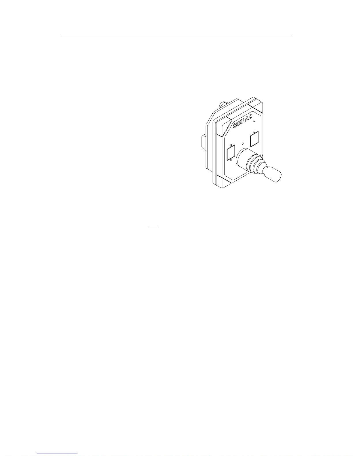
The QS50 Quick Stick is a 2
axis joystick for arm rest and
desktop mounting. It is
designed for operation in an
AP50 autopilot system and is
interfaced to the autopilot via
Robnet. Mode change is made
directly with the joystick and
by means of push buttons
thruster and WORK mode can
be toggled On/Off.
NFU power steering is
provided with an automatic
center rudder function.
Note The QS50 has not been approved in accordance with the
European Marine Equipment Directive 96/98/EC (MED) and
accordingly it can not be used in an EC type examined
(Wheelmarked) navigation system.
1.2 How to use this manual
This manual is intended as a reference guide for operating and
correctly installing the Simrad QS50 Quick Stick.
Please take time to read the manual to get a thorough
understanding of the use of the quick stick and its relationship to
a complete autopilot system.
Page 6
Simrad QS50 Quick Stick
6 20222246 / Rev. A
2 OPERATION
When operating an autopilot system of multiple control units and
steering levers, control is accessible from every control station
connected to the system. One station (autopilot control unit,
FU50 Follow Up lever or QS50) is "active" and provides the
user with access to the respective mode functions. All remaining
units are "inactive" and have no effect on course changes.
Mode indicators
All off: Autopilot is off or disengaged
One lit: QS50 is in control
One pulsating: Another unit is in control
One flashing: QS50 is locked and not in control
Two flashing: System alarm
All in sequence: Local alarm on QS50
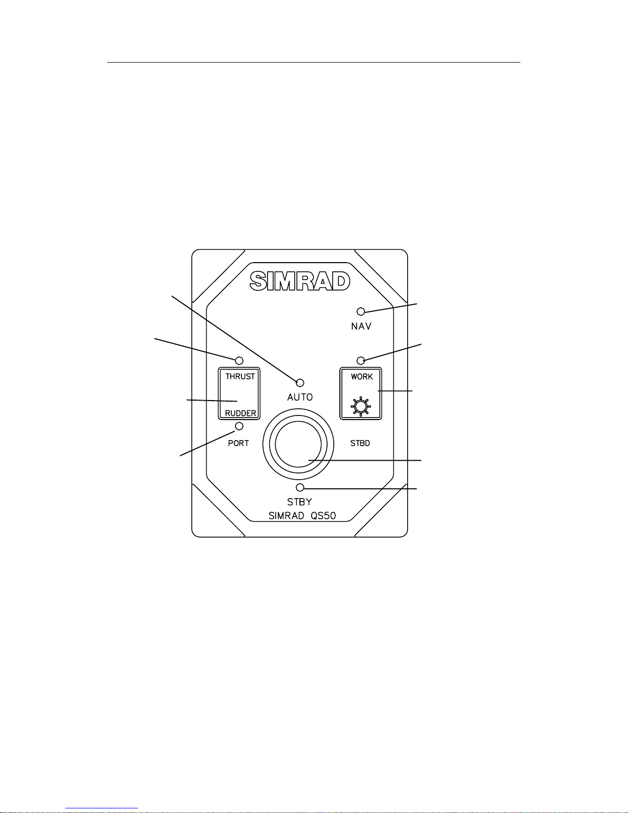
Joystick
NAV mode
indicator
AUTO mode
indicator
THRUSTER and
RUDDER selector
button
STBY mode
indicator
WORK mode
and Illumination
button
Thruster
indicator
WORK mode
indicator
Rudder
indicator
Page 7

Operation
20222246 / Rev. A 7
2.1 Power On/Off
The autopilot system is turned on from a control unit where
system status is displayed during start-up. The STBY mode
indicator on the QS50 will pulsate at turn-on and the boat can be
steered manually by the wheel.
The autopilot system is turned off from a control unit by
pressing and holding the STBY button for approx. three
seconds.
2.2 Activating the QS50
On an “inactive” QS50 one of the mode indicators will pulsate
to show the autopilot system mode.
A single press on the joystick towards the STBY or AUTO
mode indicator will transfer command to the QS50. The QS50
becomes “active” in that mode as confirmed by a steady mode
indicator; e.g. from pulsating STBY mode press the joystick
towards the AUTO mode indicator and the system will be in
AUTO mode. (Refer also to Lock Function, page
10.)
The QS50 can also be activated directly into the Work mode by
a single press on the WORK button.
2.3 Mode Selection
Standby mode
Press the joystick towards the STBY indicator to select Standby
mode. A beep and steady light in the STBY indicator confirms
that Standby mode is selected.
Press the joystick to PORT or STBD for port or starboard
rudder commands. The rudder will move as long as the joystick
is pressed.
A single press of the joystick towards STBY while in Standby
mode will command the rudder to mid-position with a short
beep when the rudder is centered.
Page 8

Simrad QS50 Quick Stick
8 20222246 / Rev. A
Auto mode
Press the joystick towards the AUTO indicator to select AUTO
mode. A beep and steady light in the AUTO indicator confirms
that the AUTO mode is selected.
The QS50 automatically selects the boat’s current heading as
the set course.
The set course will change 1° each time the joystick is pressed
to PORT or STBD. If you keep the joystick pressed, the course
automatically changes at a rate of 5° per second. Each beep
indicates a one degree course change.
Work mode
The AUTO-WORK mode is an automatic steering mode to be
used under operational conditions different from those normally
found when a vessel is in transit on a pre-set course. Examples
are trawling, towing, trolling on one engine, slow speed,
thruster use, etc.
In such situations, some boats may need different settings. Refer
to the AP50 manual for information and setup of the Work
parameters.
Press the WORK button to toggle between AUTO and AUTOWORK mode. When AUTO-WORK mode is selected, the
WORK indicator on QS50 is lit in addition to the AUTO
indicator.
Nav mode
NAV mode can not be selected from the QS50. This is a safety
feature to avoid turning in a direction you may not be aware of
(no display). When NAV mode is selected on an autopilot
control unit, the NAV mode indicator on the QS50 is pulsating.
When NAV-WORK mode is selected on the autopilot control
unit, the WORK and NAV indicators on QS50 are pulsating.
Page 9

Operation
20222246 / Rev. A 9
2.4 Thruster Function
Short press
Long press
If the vessel is equipped with a bow thruster, it can be interfaced
to the AP50 system via the optional TI51 Thruster Interface.
The vessel can then be controlled by the rudder, the thruster, or
both rudder and thruster.
After connecting a thruster to the autopilot system (see the TI51
manual) the thruster type must be selected under the AP50
Installation Dockside menu (Refer to the AP50 Instruction
Manual).
A thruster icon
below the mode index on the autopilot screen
indicates that a thruster is connected to the system.
From an activated QS50 you can now select one of three
steering functions when pressing the Thrust/Rudder button and
observing the LED indicators: Rudder only, Rudder + Thruster,
or Thruster only. An optional 3-position rotary switch is also
available for this operation (P/N 22089213).
Activation/deactivation of the thruster
In Standby and Auto-Work mode a short press on the
Thrust/Rudder button activates or deactivates the thruster. When
the thrust indicator is lit, the thruster is active and used to
maintain the boat’s heading.
If only the thruster is active and you deactivate it, the rudder
will be activated automatically.
In Auto mode the rudder only can be used to maintain the
heading and the thruster can not be activated. A short press on
the Thrust/Rudder button in Auto mode makes however the
thrust indicator pulsating if the thruster control is enabled from
the autopilot control unit. When Standby or Work mode then is
selected, both the thruster and rudder will be active and used to
maintain the boat’s heading.
Activation/deactivation of the rudder
In Standby and Auto-Work mode a long press on the
Thrust/Rudder button activates or deactivates the rudder. When
the rudder indicator is lit, the rudder is active and used to
maintain the boat’s heading.
If only the rudder is active and you deactivate it, the thruster
will be activated.
In Standby and Auto-Work mode both the rudder and thruster
Page 10

Simrad QS50 Quick Stick
10 20222246 / Rev. A
can be activated at the same time and used to maintain the
boat’s heading.
In Auto mode the rudder is always activated. If you try to
deactivate the rudder, the thrust indicator starts pulsating. That
means if Stby or Auto-Work mode is selected, the thruster is
activated and used to maintain the boat’s heading while the
rudder is deactivated.
Steering Function Panel
If a Steering Function Panel (P/N 22089213) or similar is
installed and connected to TI51 the Thrust/Rudder button on
QS50 Quick Stick is deactivated.
2.5 Lock Function
The "LOCK" function is a safety feature in the autopilot. In a
multistation system it will disable all other control units except
for the single, user selected control unit location. The “lock”
function can not be activated from the joystick.
When the "lock" function is in use, the "active" control unit stays
in command. The joystick will not respond when the buttons are
pressed, only the corresponding mode indicator will flash to
show the selected mode on the “active” unit.
System Disengaged (J50 only)
The “System select” (Sys. Sel.) input signal of the J50 (TB14) can
be used to alternate between the boat’s own steering and the
autopilot control system from an external system selector (ref.
IMO res. MSC.64 sec. 4).
When the (Sys. Sel.) signal is closed to autopilot Gnd (TB14), the
autopilot system will be disconnected from the vessel’s own
steering system and show “Disengaged” on the display (no mode
indicators lit on QS50).
The control has to be regained manually from a control unit or the
QS50.
When the “Sys. Sel.” input line is reopened after being closed, the
autopilot will go to AUTO mode and the AUTO indicator on
QS50 will pulsate.
Page 11

Operation
20222246 / Rev. A 11
2.6 Illumination
At turn on the light intensity of buttons and mode indicators
are set to day level. Press the WORK button for more than
3 seconds to toggle between the day and night level.
2.7 Alarms
Alarm messages are indicated by flashing of all mode indicators
except the one showing the present steering mode.
Internal error with push button, joystick button or Robnet
communication is indicated by “rotating” lighting of all
indicators.
The audible alarm can be reset from the QS50 by pressing any
button or the joystick.
Alarm messages can only be reset from a control unit; carefully
read the alarm text first.
Page 12
Simrad QS50 Quick Stick
12 20222246 / Rev. A
3 INSTALLATION
3.1 Mounting
The QS50 is designed for arm rest or desktop mounting, indoor
or outdoor. It should be installed where it is most convenient for
the user, and with special regard to environmental specifications
for the unit.
The mounting surface must be flat and even to within 0.5 mm.
• Drill the 4 mounting holes and make a panel cutout according
to the supplied template.
• Use the supplied gasket between the panel and the unit.
• Use the supplied 19 mm screws to fasten the joystick unit to
the panel.
• Apply the front panel corners.
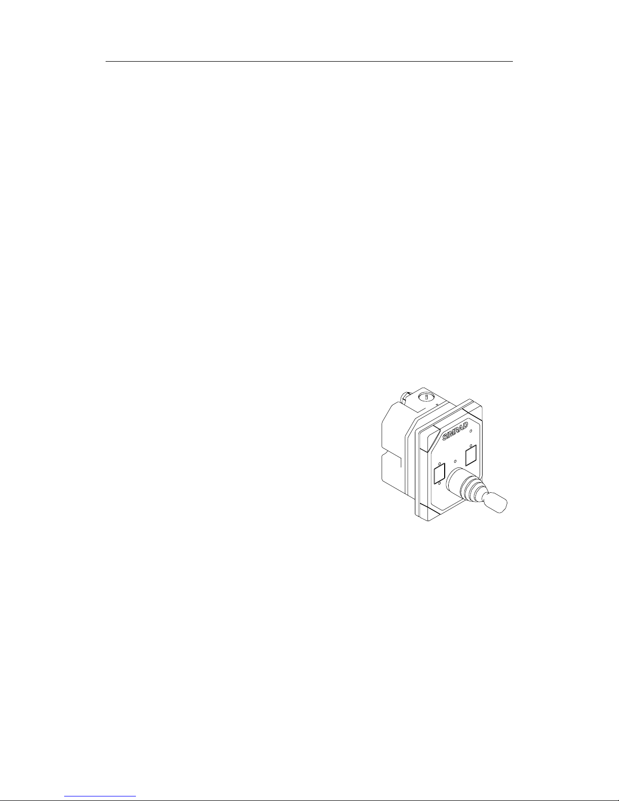
Optional back cover
For mounting in exposed
environments, the QS50 can be
supplied with an optional back
cover. See page
20 for depth of unit.
The optional back cover has a cable
gland at the bottom. The cable gland
can also be mounted on side of the
back cover.
Page 13
Installation
20222246 / Rev. A 13
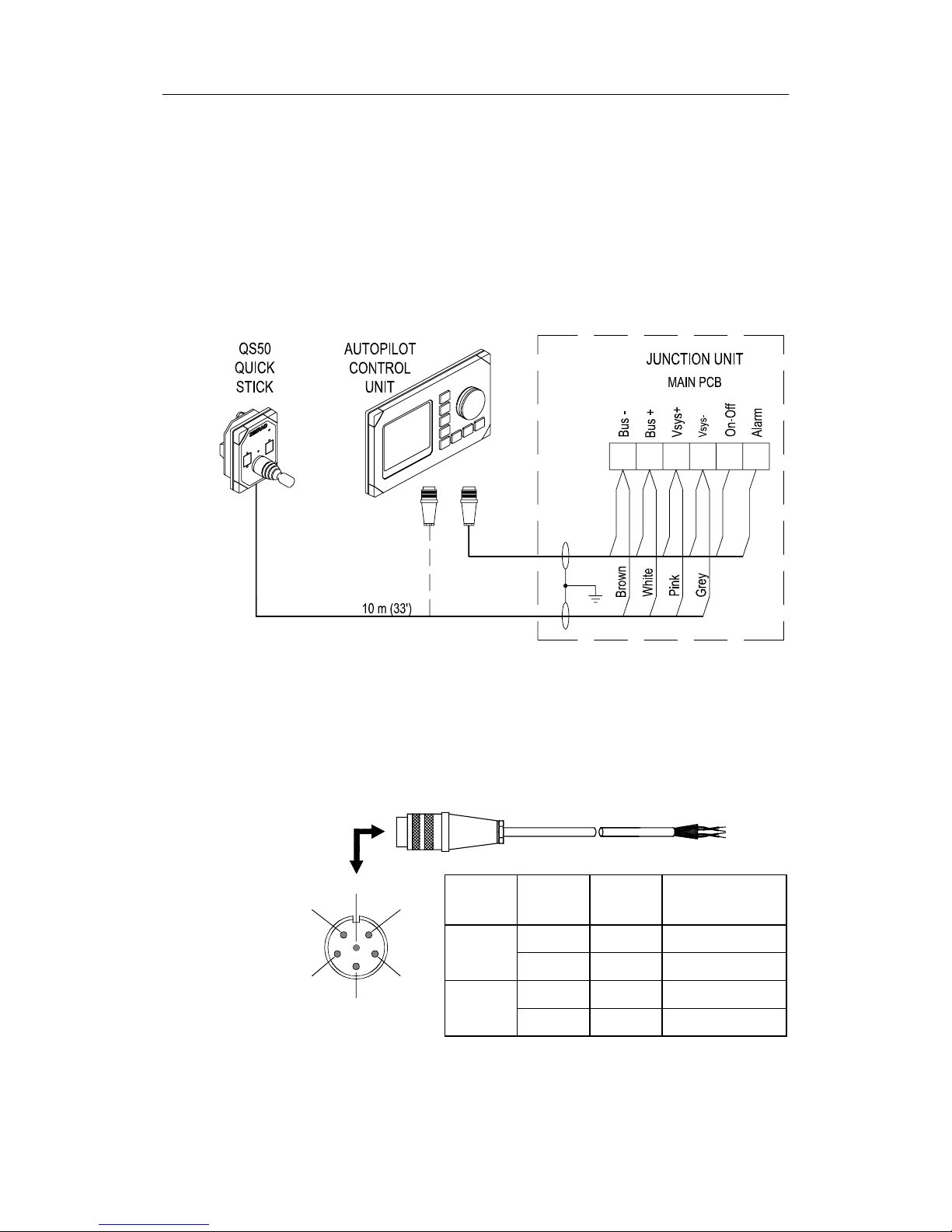
3.2 QS50 connection
The QS50 is supplied with 10 m (33’) cable with one open end.
The QS50 is hard wired to the autopilot junction unit. Strip about
25 mm (1’) of the cable insulation and pull the shield backwards.
Secure the cable the same way as the other cables in the junction
unit and connect the wires in parallel with the cable shown on
Figure 3-1 using the same color code.
Figure 3-1 QS50 connection
Alternatively, a Robnet male connector (P/N 44160844) can be
mounted to the cable and plugged directly into the autopilot
control unit or any other device in the system containing a
Robnet connector. Refer to
Figure 3-2 for pin configuration and
color code of the network cable.
Cable
pairs
Color
code
Pin Signal
1st pair Pink 5 V SYSTEM+
Grey 4 V SYSTEM–
2nd pair Brown 1 Bus–
5
42
1
6
FRONT VIEW
3
White 2 Bus+
Figure 3-2 Robnet Plug Pin Configuration
Page 14

Simrad QS50 Quick Stick
14 20222246 / Rev. A
Internal connection
The unit is opened by removing the four screws on the back
cover. See
Figure 5-2. Inside there is a printed circuit board with
plug-in terminals. The cable is connected to the terminal
according to
Figure 3-3. The cable screen must be connected to
the ground terminal inside the back cover.
Figure 3-3 QS50 Internal connections
Page 15

Maintenance
20222246 / Rev. A 15
4 MAINTENANCE
Under normal use, the joystick will require little maintenance.
If the unit requires any form of cleaning, use fresh water and a
mild soap solution (not a detergent). It is important to avoid
using chemical cleaners and hydrocarbons such as diesel, petrol,
etc.
Page 16

Simrad QS50 Quick Stick
16 20222246 / Rev. A
5 SERVICE
5.1 How to replace a defective joystick
Refer to Figure 5-1 and Figure 6-1.
Figure 5-1 Joystick connections
Page 17

Maintenance
20222246 / Rev. A 17
5.2 How to replace the back cover
Also refer to spare parts list, section 6.
Figure 5-2
Figure 5-3
• Remove the four
countersunk screws (11)
• Remove the back cover (3)
• Disconnect the cable, see
Figure 3-3
• Remove the cable and the
gland (6)
• Insert the cable and the gland (6) on
the optional cover (12) and connect
the cable
• Mount the optional outdoor cover to
the front (1) by means of the 4
supplied screws (13)
Page 18

Simrad QS50 Quick Stick
18 20222246 / Rev. A
6 SPARE PARTS LIST
22089437 1 QS50 Front
22089403 2 QS50 Board Ass’y
22089478 3 QS50 Cover
44171726 4 Joystick 4-position
44171791 Joystick cover
44171734 5 Contact Block
44140796 6 Cable gland, PG7
22084529 7 Cabinet corner
44165181 8 Screw 3,5x19
22089502 9 QS50 Gasket for panel mount
44151272 10 Screw M4x6 PAN
44148898 11 Screw M4x12 Countersunk
22089734 12 QS50 Optional outdoor cover (see
Figure 5-3)
44158129 13 Screw M4x12 (for optional cover)
22089825 Cable, 10 m (33’)
Figure 6-1 Exploded view
Page 19

Technical Specifications
20222246 / Rev. A 19
7 TECHNICAL SPECIFICATIONS
Dimensions:..................................................................................... See Figure 7-1.
Weight: ...................................................................1.0 kg (2.2 lbs) including cable
Material:.............................................................................Epoxy coated aluminum
Supply:..............................................................12-32VDC –10%+30% via Robnet
Power consumption: ...................................................................................... 1.3 W
Environmental protection:...............................................................IP56 from front
With optional back cover .......................................................IP56
Compass safe distance:.....................................................................0.15 m (0.5 ft.)
Temperature:
Operating:..........................................................–25 to +55°C (–13 to +130°F)
Storage: .............................................................–30 to +70°C (–22 to +158°F)
Cable: ....................................10 m (33’) cable with three (3) twisted pairs of wire
The cable runs through a cable gland.
Autopilot interface:..........................................................................Via Robnet bus
Figure 7-1 QS50 Dimensions
Page 20

Simrad QS50 Quick Stick
20 20222246 / Rev. A
Figure 7-2 QS50 with optional cover
 Loading...