

Page 1

Instruction manual
TE CH NO LO GY FO R SUS TA IN AB LE FI SH ER IE S
www.simrad.com
(CD012221-002)
Simrad PI Geometry
Sensor system for trawl and danish seine
Page 2

Page 3

SimradPIGeometry
Instructionmanual
Thisdocumentgivesyouthenecessaryinformationfor
mounting,chargingandmaintainingthePIGeometry
sensor.ItalsoexplainshowtosetupthePI44andPI54catch
monitoringsystemstoreceiveanddisplaytheinformation
providedbythesensor.
322482/B
13.02.2009
Page 4

Documenthistory
KongsbergM a r it imeA S
Strandprom e n a de n5 0
P.O.Bo x1 11
N- 3 1 91H o rten ,N o rway
S im ra d
Teleph on e :+ 4 73 30 34 00 0
Telefa x:+ 473 30 42 98 7
contact@ s im ra d . com
w w w .s im r a d . c o m
Documentnumber:322482/ISBN-13:978-82-8066-102-9/Currentversion:Rev.B
Rev.A15.09.2008
Rev.B
13.02.2009
Firstrelease.
Minorchangestobatterylifetime.
Copyright
©2009KongsbergMaritimeAS
TheinformationcontainedinthisdocumentremainsthesolepropertyofKongsbergMaritimeAS.Nopart
ofthisdocumentmaybecopiedorreproducedinanyformorbyanymeans,andtheinformationcontained
withinitisnottobecommunicatedtoathirdparty ,withoutthepriorwrittenconsentofKongsberg
MaritimeAS.Thedocument,oranypartofit,maynotbetranslatedtoanyotherlanguagewithoutthe
writtenapprovalfromKongsbergMaritimeAS.
Disclaimer
KongsbergMaritimeASendeavourstoensurethatallinformationinthisdocumentiscorrectandfairly
stated,butdoesnotacceptliabilityforanyerrorsoromissions.
Warning
Theequipmenttowhichthismanualappliesmustonlybeusedforthepurposeforwhichitwas
designed.Improperuseormaintenancemaycausedamagetotheequipmentand/orinjuryto
personnel.Theusermustbefamiliarwiththecontentsoftheappropriatemanualsbeforeattempting
toinstall,operateorworkontheequipment.
KongsbergMaritimeASdisclaimsanyresponsibilityfordamageorinjurycausedbyimproper
installation,useormaintenanceoftheequipment.
Support
IfyourequiremaintenanceonyourSimradproductcontactyourlocaldealer.Y oucanalsocontactususing
thefollowingaddress:s
w w . s i m r a d . c o m .Onourwebsiteyouwillalsondalistofourdealersanddistributors.
visitw
i m r a d . s u p p o r t @ s i m r a d . c o m .Ifyouneedinformationaboutourotherproducts,
Page 5

Instructionmanual
Tableofcontents
INTRODUCTION................................................................5
Purposeandapplications..........................................................................................5
Mainpartsidentication...........................................................................................7
Informationonthesensoridenticationlabel..........................................................8
TheSimradMini-Rresponder..................................................................................8
Responder,mainpartsidentication...............................................................9
Informationontheresponderidenticationlabel...........................................10
WhyusethePIGeometrysensorsystem...............................................................10
INSTALLATION...............................................................13
PIGeometrysensorinstallation.............................................................................13
Mini-Rresponderinstallationsonthetrawldoors.................................................15
Adapterinstallation................................................................................................15
Installationprinciples.............................................................................................15
CONFIGURATION............................................................17
Basicconguration.................................................................................................17
CongurationofthePI32.......................................................................................18
CongurationofthePI44andPI54........................................................................18
Aboutsensorconguration....................................................................................20
Defaultcommunicationchannelsandupdaterates.........................................20
Changingacommunicationchannel.............................................................20
Changingtheupdaterate.............................................................................21
PICongurator...........................................................................................22
DISPLAYPRESENTATIONS..............................................23
Numericalpresentation...........................................................................................23
GraphicpresentationonPI32.................................................................................24
GraphicpresentationonPI44andPI54..................................................................24
CHARGINGANDMAINTENANCE......................................27
PIGeometrymaintenance......................................................................................27
PIMini-Rmaintenance..........................................................................................28
PIGeometrycharging.............................................................................................29
PIMini-Rcharging.................................................................................................29
HowtousetheSimradPICharger.........................................................................30
Dailyoperation...........................................................................................30
Indicators...................................................................................................32
Automaticconguration..............................................................................32
HowtousetheSimradPIMiniCharger.................................................................33
DailyoperationofthePIMiniCharger..........................................................33
322482/B
3
Page 6

SimradPIGeometry
PIMiniChargerindicators...........................................................................34
HowtousetheSimradPIMaxiCharger.................................................................34
DailyoperationofthePIMaxiCharger.........................................................35
PIMaxiChargerindicators...........................................................................36
4
322482/B
Page 7

INTRODUCTION
Purposeandapplications
Introduction
Efcientsherywithtrawlandpurseseineassumesprofessional
andadequateinstrumentationonthegear.Thismanualdescribes
installation,useandmaintenanceoftheSimradPIGeometry
sensorwhenputtousewithoneoftheSimradPIcatch
monitoringsystems.
ThepurposeoftheSimradPIGeometrysensorsystemisto
monitorthegeometryofyourtrawlordanishseine.Thisis
achievedbymakingaccuratemeasurementsofthedistances
betweenthecentreoftheheadropeabovethetrawlopening(or
thefootropeatthebottom)andeachofthetrawldoorsorwing
ends.Ifthesedistancesarenotidenticalthetrawl(ordanish
seine)willbeskewedandunbalanced,andthisreducesthecatch
efciency.TheSimradPIGeometrysensorsystemhasbeen
developedtobeusedonbothbottomandpelagictrawls,aswell
aspairtrawlsanddanishseiners.InadditiontothePIGeometry
sensor,thesystemusestwoPIMini-Rtransponders.Theseare
mountedonthetrawldoors(ortrawlwings).
Note
TwoPIGeometrysensorcongurationsareavailable,
thestandardtypeandtheXT .ThestandardPIGeometry
congurationisusedwhenthedistancebetweenthePIGeometry
sensorandthetrawldoorsisbelow300meters,andwillprovide
thebestaccuracyforshorterdistances.ThePIGeometryXT
congurationcanbeusedformaximumdistancesupto600
meters.TheXTcongurationdoesnotprovidethesameaccuracy
asthestandardconguration.Usethisonlyifthestandard
congurationcannotbeused.T ochangeconguration,usethe
PIConguratorapplication.
Theresultsfromthemeasurementsaretransmittedbyacoustic
signalstothePIcatchmonitoringsystemmountedonthevessel,
andifnecessaryyoucantakecorrectiveactions.
322482/B
5
Page 8
SimradPIGeometry
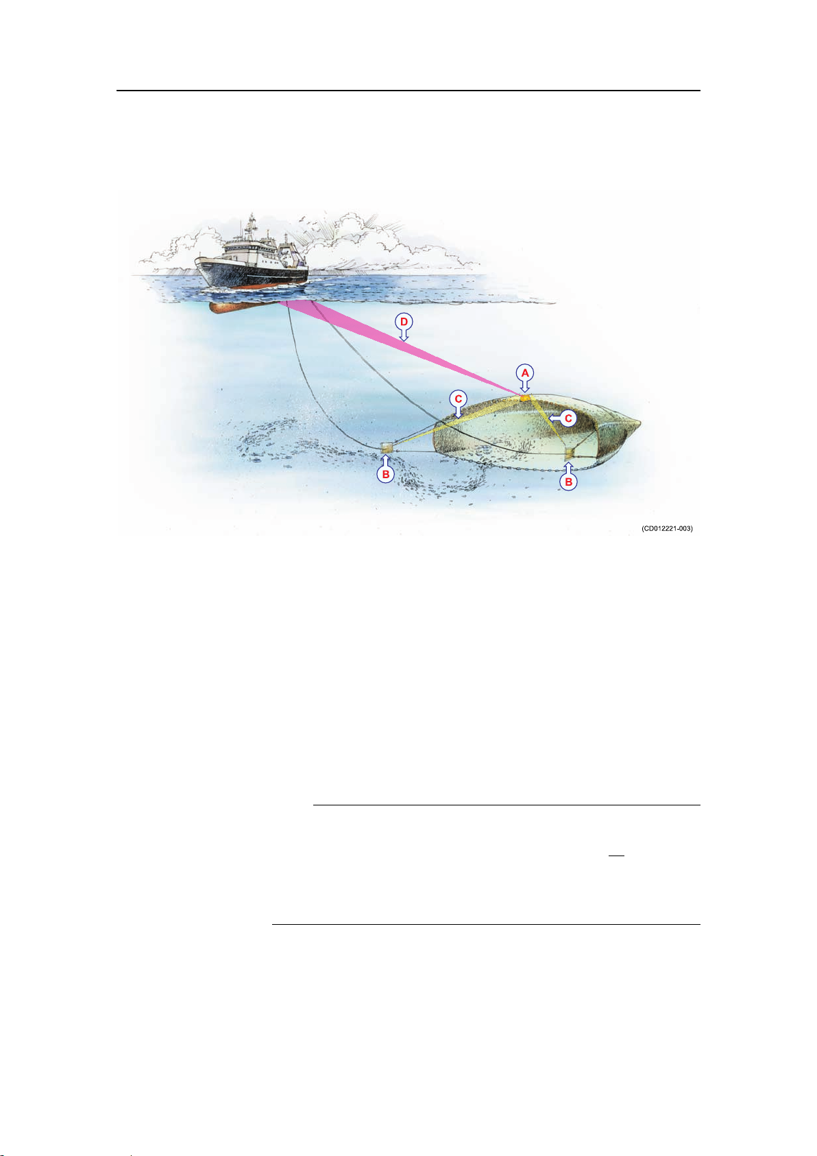
Figure1ThePIGeometrysensorapplication
AThePIGeometrysensorismountedattheexactcentreof
theheadropeorfootrope.
BThetwoMini-Rrespondersaremountedoneachtrawldoor
ortrawlwing.
CEachofthetwoMini-Rresponderscommunicatewiththe
PIGeometrysensortomeasurethedistances.
DThePIGeometrysensorusesanacousticlinktotransmit
theresultsfromthedistancemeasurementstothePIsystem
onthevessel.
TwosetsofPIGeometrysensorswithcorrespondingMini-R
responderscanbeusedsimultaneously.
Note
EachPIGeometrysensorcanbesetuptocommunicatewithone
oftwosetsofMini–Rresponders;number1and3o
r number
2and4.MakesurethatthePIGeometrysensorislabelled
accordingly,andensurethatyouonlyusethesensorwiththe
correctpairofresponders.
Relatedtopics
•Installationprinciplesonpage15
6
322482/B
Page 9
Introduction
Mainpartsidentication
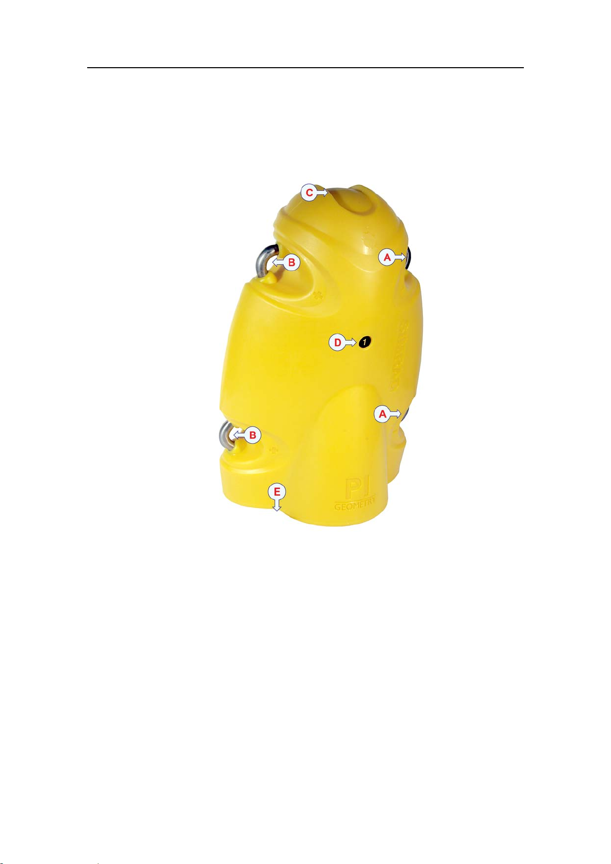
Figure2ThePIGeometrysensor,mainpartsidentication
ANegativechargingandfasteninglug.
BPositivechargingandfasteninglug.
CCommunicationlinktothevesselandtotheresponders.
DGeometrysetidentication.
ELocationofwaterswitchandsensoridenticationlabel.
322482/B
7
Page 10
SimradPIGeometry
Informationonthesensoridenticationlabel
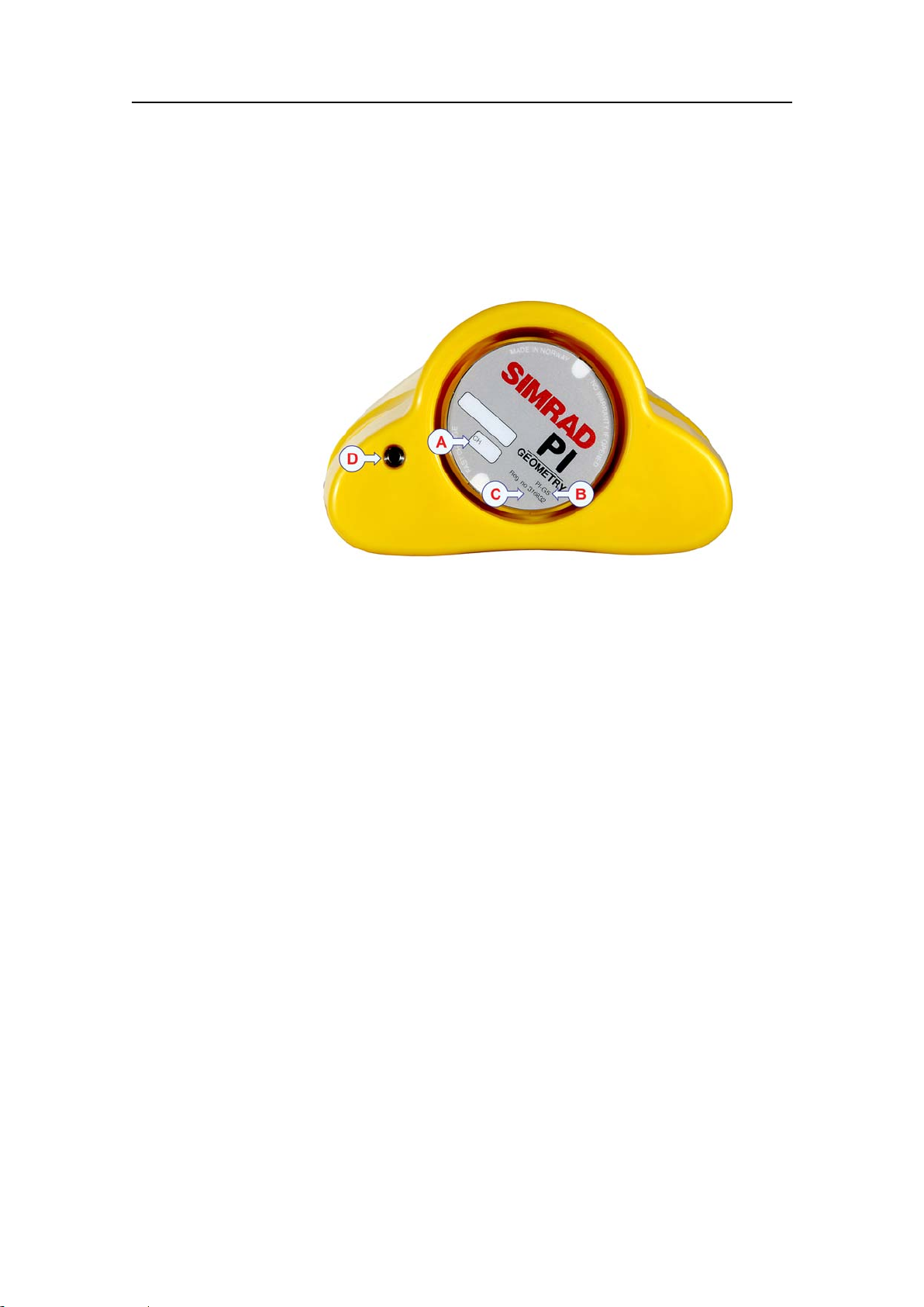
ThesensorPIGeometrylabelprovidesthefollowinginformation.
Figure3ThePIGeometrysensorlabel
TheSimradMini-Rresponder
AChannelidentication.Youmustwritedownthechannel
currentlyusedbythesensortocommunicatewiththePI
system.
BThisinformationidentiesthesensortype.
COrdernumber.
DWaterswitch.Thisisasacricialbolt.Theboltwill
graduallybewornout.Checkitfromtimetotimetoremove
corrosion,orreplaceitifnecessary .
EachPIGeometrysensorneedstwoMini-Rresponders,oneon
eachtrawldoororwing.Thetworespondersmustbeinstalled
withtheexactsamedistancesfromthePIGeometrysensor.The
communicationtransducernexttotheidenticationlabeloneach
respondermustpointtowardsthePIGeometrysensoronthe
middleoftheheadropeorfootrope.
Thetworespondersarettedwithlabelsidentifyingtheir
physicallocations:
•Redcolourisusedfortheporttrawldoor(orwing)
•Greencolourisusedforthestarboardtrawldoor(orwing)
8
322482/B
Page 11
Responder,mainpartsidentication
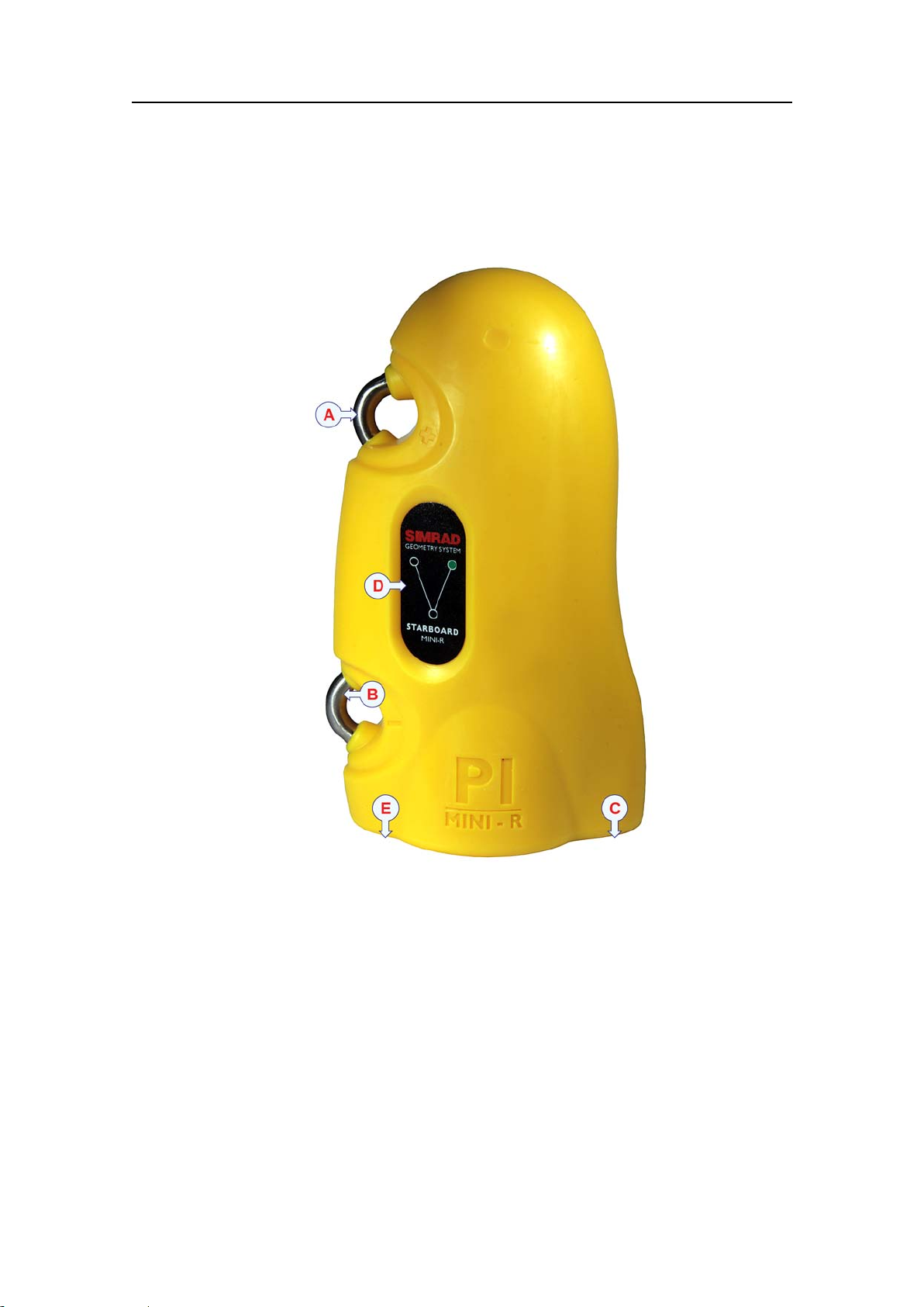
Figure4PIMini-Rresponder ,mainpartsidentication
Introduction
ANegativechargingandfasteninglug.
BPositivechargingandfasteninglug.
CCommunicationlinktothePIGeometrysensor
DResponderidentication(portorstarboard)
ELocationofwaterswitchandsensoridenticationlabel.
322482/B
9
Page 12

SimradPIGeometry
Informationontheresponderidentication
label
TheSimradPIMini-Rresponderlabelprovidesthefollowing
information.
Figure5PIMini-Rresponder ,informationonthesensor
identicationlabel
APositionidentication.Redcolouridentiestheport
responder,whilegreencolouridentiesthestarboard
responder.
BThisinformationidentiesthesensortype.
COrdernumber.
DWaterswitch.Thisisasacricialbolt.Theboltwill
graduallybewornout.Checkitfromtimetotimetoremove
corrosion,orreplaceitifnecessary .
ETransducerforcommunicationwiththePIGeometrysensor.
WhyusethePIGeometrysensorsystem
Inordertomaximizetheperformanceandthecatchefciency,
thetrawlandthewarpsmustbeadjustedproperly .Thisis
essentialtoensureasquaretrawlandminimumskew.Thisis
alsoimportantfordanishseines,astheropesmusthaveidentical
length.
Anydisturbancetothetrawlmovementsmayhaveanegative
effectonthecatch.Thisisparticularlyimportantonabottom
trawl.Askewedbottomtrawlwillresultinunstablebottom
contact,andcreateescaperoutesforshbelowthegearand
throughthesidepanels.Onpelagictrawlsanddanishseinesa
10
322482/B
Page 13

Introduction
A
A
B
B
C
C
(CD012221-008)
skewednetwillmakethegearunstable,andthecatchbereduced.
Optimaltrawlgeometryisthereforevitalformaintainingthe
catchefciency.
Atrawlordanishseinemaybeskewedforseveralreasons.Some
ofthesereasonsare:
•Incorrectriggingoftrawl,sweeplinesortrawldoors
•Misadjustedwarplengths
•Sidecurrent
•Towinginsteeporslopededges
Figure6Askewedtrawl
Onthelefttrawl,distance“A”ontheportsideislongerthan
distance“B”onthestarboardside.Thetrawlisunbalanced.On
therighttrawl,thedistancesareidentical.Measuringthedoor
spread(“C”)willnotdetectadistortedtrawlgeometry.
Iftheriggingofthetrawliscorrect,youcaneasilycompensate
forskewbyadjustingeitherportorstarboardwirelength.
ThePIGeometrysensorsystemisbasedonthefactthata
correctriggedtrawlanddanishseinehasexactlythesame
distancemeasuredfromthecentreoftheheadropeorfootrope
toeitherdoorortrawlwing.Thesedistancesmustbeidentical
independentofweatherconditions,seastateorwatercurrents.
322482/B
11
Page 14

SimradPIGeometry
Advantagesinsummary
•Bottomandpelagictrawls:
–Measuresifthetrawlisskewed.
–Allowsyoutocorrectthetrawlgeometrybyadjustingthe
warplengths.
•Danishseine:
–Detectsvariationsinthedistancefromthecentreofthe
headrope(orfootrope)toeitherwingoftheseine.
–Detectsdifferencesintheropelengthswhentheseineis
closed(distancesbetweenthewingsshouldthenbeclose
tozero).
12
322482/B
Page 15

INSTALLATION
PIGeometrysensorinstallation
Installation
ThePIGeometrysensorismountedattheexactcentreofthe
trawlordanishseineopening,eitherattheheadropeatthetopof
theopening,oratthefootropeatthebottom.Inbothlocations
itmustbemountedwiththecommunicationtransducersfacing
o r w a r d .ThetwoMini-Rrespondersarenormallyinstalledon
f
thetrawldoorsortrawlwings.Fromthisposition,theywill
communicatewiththePIGeometrysensor.
ThePIGeometrysensormustbemountedattheexactcentreof
thetrawlordanishseineopening.Themostcommonlocationis
attheheadropeatthetopoftheopening.Itmayhoweveralso
beplaceatthefootrope.
Note
Ensurethatyoumountthesensorwiththetransduceropening
facingforward.Theremustbeaclearlineofsightbetweenthe
transduceronthePIGeometrysensorandthetransducersonthe
Mini-Rresponders.TheSIMRADprintonthesensor(C)must
pointuptowardsthewatersurface!
322482/B
13
Page 16

SimradPIGeometry
Figure7PIGeometrysensorinstallation
AForwardfasteninglugswithsnaphooksandrope
BAftfasteninglugswithsnaphooksandrubberbands
CPIGeometrysensor,top
Recommendedprocedure
1Assembleabagofne-meshednet,andtiethisbagtothe
trawlatthemiddleoftheheadrope.
2Placethesensorinsidethisbag.
3Securethetwoforwardfasteninglugs(A)onthesensor
usingtwosnaphooksandrope.
4Securethetwoaftfasteninglugs(B)onthesensorusing
snaphooksandstrongrubberbands.
Thismountingplacesthesensorinacradlesupportedon
allfoursides.
5Ensurethatthesensorisproperlymounted.Checkthatitis
notpermittedtomovesidewaysduringtheshingoperation,
asthismayleadtoacommunicationfailure.
6Makesurethatyouhavebestpossiblefreeviewbetweenthe
PIGeometrysensorandtheMini-Rrespondersonthetrawl
doors,andbetweenthesensorandthevessel.
14
322482/B
Page 17

Mini-Rresponderinstallationsonthetrawldoors
WerecommendthatthetwoMini-Rrespondersaremountedin
dedicatedadaptersoneachtrawldoor.Theseadaptersmustbe
installedbeforehand.Detailedinformationonhowtoinstallthe
adaptersareprovidedwiththeinstallationkit.Youmayalso
mounttherespondersusingothermethodsprovidedthattheyare
properlysecuredandfacingthecorrectdirections.
Note
Itisessentialthatthereisaclearlineofsightbetweenthe
communicationtransducernexttotheidenticationlabelon
eachofthetwoMini–RrespondersandthePIGeometrysensor
mountedatthetop(orbottom)ofthetrawlopening.
Eachrespondermustalwaysbeinstalledinsuchawaythat
its“rearend”withtheidenticationlabelandcommunication
transducerpointsdirectlytowardsthePIGeometrysensorat
thetoporbottomofthetrawlopening.Thecorrectangleof
installationmustbechosentomatchtheangleofthetrawldoor
duringnormaltow.Therecommendedresponderinstallation
angleforatrawldoorwithangleofattack37degreesis
approximately15degrees.Y oumusthoweveradjustthisangle
dependingonthelengthofthechainsbetweenthetrawldoorand
thetrawl,andtheoperationalpropertiesofthetrawldoor.Ifin
doubt,consultthetrawldoormanufacturer.
Installation
Adapterinstallation
Installationprinciples
Thetworubberinsertsprovidedatthebottomofeachsensor
adaptermustnotbereplacedwithanyothertypesordesigns.
Itisessentialthattheseinsertsprovideasecurecradleforthe
sensors,buttheymustalsoallowforfreewatercirculationto
allowthesensor’swaterswitchtoengage.Also,thedesignof
theinsertsallowssandandmudtoowoutwhenthetrawldoors
arepulledupfromthewater.
Theinstallationofthesensoradaptersisdescribedinthe
dedicatedinstructionmanualprovidedwiththeadapters.The
documentcanalsobedownloadedfromh
BymeasuringthedistancesbetweenthePIGeometrysensor
andeachofthetwoMini-Rresponders,thesensorsystem
cancomparethem.Thetwodistances“x”and“y”musthave
identicallength.Ifthelengthof“x”or“y”changes,thetrawl
inunbalanced,andthemessagefromthePIGeometrysensor
tothePIsystemonthebridgewillprovidethisinformation
immediately.
t t p : / / w w w . s i m r a d . c o m .
322482/B
15
Page 18

SimradPIGeometry
0000000
0000000
0000000
0000000
A
B B
C C
D
x
y
Figure8Installationprinciples
AThePIGeometrysensorismountedbehindtheheadropeat
thetopofthetrawlopening,orbehindthefootropeatthe
bottom.
BThetwoMini-Rrespondersarenormallymountedin
dedicatedadaptersonthetwotrawldoors.Theymayalso
bemountedonthetrawlwings.
CCommunicationlinksbetweenthePIGeometrysensorand
twoMini-Rresponders.
DCommunicationlinkbetweenthePIGeometrysensorand
thePIhydrophonebelowthevesselhull.
16
322482/B
Page 19

Conguration
CONFIGURATION
InordertoallowtheinformationfromthePIGeometrysensorto
beacceptedandunderstoodbythePIcatchmonitoringsystem,
thePIreceivermustbesetupcorrectly.Thismeansthatyou
musttellthereceiverthatthesensorexistsbyenteringthe
sensortype,communicationchannelsandupdaterate.Formore
detailedinformationaboutthesettingsandparameters,referto
therelevantoperatorand/orreferencemanuals.
Upondelivery,allPIGeometrysensorsaresetupwithfactory
defaultchannelsandupdaterates.Refertothetableinsection
Aboutsensorcongurationonpage20.
Note
ThesensorandthePIsystemsetupmustcorrespond,otherwise
thecommunicationwillnotwork.Tochangethesensorsetup
(channelselectionandupdaterate),usethePICongurator
utility.SeePIConguratoronpage22.
Basicconguration
Basicsettings
•WhenyouputthePIGeometrytouse,youmustsetitup
withoneuniquesensornumberwithtwomeasurements.
Onlyoneupdateratecanbechosen,thisiscommonforboth
measurements.Thechannelnumbersaredenedindividually
forthetwomeasurements.Boththeupdaterateandthe
channelnumbersmustbechosenaccordingtothesensor’s
conguration.Writedownthiscongurationforfuture
reference.Fordefaultsettings,refertothetableinsection
Aboutsensorcongurationonpage20.
•IfyourPIsystemisttedwithMMIsoftwareversion0.50
andDSPsoftwareversion1.11.(orlater),usethefollowing
recommendedreceiversettings:
–Interferencelter:On
–Interferencelterlevel:8
–Sensorlter:Light
–Catch/Bottomsensorlter:Light
–AGC:Off
–Manualgain:20dB
–Multipathlter:On
–W aterprole:Salt
–Detectionthreshold(DT):8dB
–Maximumshootingspeed:1knot
322482/B
17
Page 20

SimradPIGeometry
•IfyourPIsystemisttedwitho l d e r softwareversionsthan
Note
TheMultipathltermustbesettoOn.
CongurationofthePI32
ThePIGeometrysensorcannotbeusedontheSimradPI32
catchmonitoringsystem.
0.50,usethefollowingrecommendations:
–Onthereceiver,theInterferenceltermustbeswitchedon.
SetittoLevel9ifyouhavenoiseproblemsfromother
hydroacousticsources.Notethatthislterswillinuence
thesignalspectrumshownintheStatusdisplay.
–W erecommendthatyousetthesensorltertoLight.
CongurationofthePI44andPI54
ThisprocedureexplainshowtosetupthePI44andPI54catch
monitoringsystemstoaccesstheinformationprovidedbythe
PIGeometrysensor.Formoredetailedinformationaboutthe
settingsandparameters,refertotherelevantoperatorand/or
referencemanual(s).
Note
InordertosetupthePI44andPI54systems,yourPIoperator
unitmustbeprovidedwithMMIsoftwareversion0.50orlater
anddigitalsignalprocessor(DSP)softwareversion1.11orlater .
Ifindoubt,checkyoursoftwareversionsontheStatusdisplay.
Werecommendthatyouusetheformatthebeginningofthe
PI44orPI54operatorand/orreferencemanualtowritedownthe
sensorsyouhaveandtheirrespectivecommunicationchannels
andupdaterates.
Note
InordertosetupthePIsystemyoumustknowwhatkindof
sensorsyouhave,whichcommunicationchannelstheyuse,and
howoftentheycommunicate(theupdaterate).Y ouneedthis
informationb
e f o r e youstartthesetupprocess.
Donotcarryoutsensorsetupunlessabsolutelynecessary.
18
322482/B
Page 21

Figure9PIGeometrycongurationexample
ThisexampleshowshowthePI44(orPI54)issetuptoreceive
informationfromaPIGeometrysensor .Notethattwochannels
areused.Standardcommunicationchannelsandupdaterates
arealsoshown.
Conguration
HowtoaccesstheSetupmenu
1PresstheMENUbuttontoopenthemainmenu.
2OntheSetupmenu,selectSensorsetup.
3PresstheENTbuttontoallowforchanges,andthenthe
samebuttononemoretimetoacceptthewarning.
Howtosetupthegeometryreadings
1Toresettheunit,setallsixsensorstodefaultsensortype
None.
2ChoosethesensorinputyouwishtouseforthePIGeometry
sensor;1to6.
3Denethesensortype(bydefaultNone)toDual.
4SetUpdatetothecorrectupdaterate.
5SetMeasure1tothechosensensortypeGeometry(0to300
m)orGeometryXT(0to600m).
6SetthecommunicationChanneltoitscorrectvalue.
7SetMeasure2tothechosensensortypeGeometryor
GeometryXT.
Note
Measure1andMeasure2mustbesettothesamesensortype!
8SetthecommunicationChanneltoitscorrectvalue.
9PresstheENTbuttontosavethechangesandexit.
322482/B
19
Page 22

SimradPIGeometry
Allsensorsareprovidedwithdefaultcommunicationchannels
andupdaterates.RefertothetableinsectionAboutsensor
congurationonpage20.
Aboutsensorconguration
AllsensorsareprovidedfromSimradwithpredened
communicationchannelsandupdaterates.
Defaultcommunicationchannelsand updaterates
Seethetablebelowfortheinitialvaluesforthecommunication
channelsandupdateratesforthevarioussensors.
Table1Defaultcommunicationchannelsandupdaterates
SensorCom.channel(s)
PIBottomContact
PICatch
PIDepthDepth300M:16
PIHeight14Fast
PIRemote/Depth
PISpread
PISpread/Depth
PITwinSpread
PITemperature8Fast
PIGeometry
PISeineSounder
6Normal
4Normal
Depth600M:12
Depth1000M:10
Depth300M:11
Depth600M:15
Depth1000M:13
2Fast
Depth300M:16
Depth600M:12
Depth1000M:10
Spread:2
2and7Fast
1and5Fast
Depth300M:5
Depth600M:9
Depth1000M:1
Height:14
Updaterate
Fast
Fast
Fast
Fast
Changingacommunicationchannel
Itmayberequiredtochangeoneormorecommunication
channels,andtheremaybemanyreasonsforthis.
•Youhavemorethanoneofeachsensor.Forexample,ifyou
havethreetemperaturesensors,theyMUSTcommunicate
onthreedifferentchannels.
20
322482/B
Page 23

Conguration
•OthervesselsnearyourusethesamePIcatchmonitoring
system(orasimilar),andtheyhaveoneormoreoftheir
sensorssetuptothesamecommunicationchannelsasyou
have.Thiswillcreateinterference,asyouwill"read"each
otherssensors.
•Ifyoursensorsaresetuptousecommunicationchannelstoo
closetoeachother(forexample,youhavechosenchannels4,
5and6),thiswilllimitthevessel’sspeed.Thereasonforthis
istheDopplereffect.Ifthespeedistoohigh,theDopplerwill
causethetransmissionfrequenciestochangesomuchthat
theyoverlap,andthiswillcreateinterference.ThePIcatch
monitoringsystemwillprovideawarningifthisisaboutto
happen!Y oumusttheneitherchangetoothercommunication
channelsfurtherapart,orreducethemaximumshootingspeed.
•Ifyouoperateatthemaximumrangeofthesensors,you
maybeabletoincreasethisrangeslightlyifyouuse
lowercommunicationchannels.Thisisbecausethelower
communicationchannelsuselowertransmissionfrequencies.
AllsensorsareprovidedfromSimradwithadefault
communicationchannel.Insomecasesyoumayndthatthe
chosenchanneldoesnotsuityouroperationalneeds,forexample
ifyouhavemorethanonesensorofanygiventype.Thisisa
decisionyouhavetomakedependingonhowmanysensorsyou
use,andhowmanyofthesethatareidentical.
Changingtheupdaterate
Itmayberequiredtochangetheupdaterateonasensor,thatis
howoftenitsendsinformationbacktothePIcatchmonitoring
system.Ahighupdateratewillgivefrequentinformation
updates,butthesensorwillusemorebatterypower.Ifyouneed
yourbatteriestolastaslongaspossible,youmustconsider
loweringtheupdaterate.
•Alowupdateratewillprovideyouwithfewerinformation
updates,butthebatterywilllastverylong.
•Ahighupdateratewillgiveyoufrequentinformationupdates,
butthebatterywillrunoutfaster.
AllsensorsareprovidedfromSimradwithadefaultupdaterate
setting.Insomecasesyoumayndthatthisupdateratedoesnot
suityouroperationalneeds.Thisisadecisionyouhavetomake
dependingonthelocalshingconditions.
322482/B
21
Page 24

SimradPIGeometry
PICongurator
Simradhasdevelopedadedicatedcomputerutilitytochange
thesensorcongurations.Bymeansofanordinarydesktop
computerandafewspecialcablesyoucandothisjobyourself.If
youdonotrequirefrequentcongurations,youcanalsocontact
youlocaldealerforassistance.Contactyourdealerformore
information.
22
322482/B
Page 25

Displaypresentations
1
X1[m]
143.
5
q
1
X2[m]
143.
5
q
(CD012221-007)
A
B
C
I
E
D
F
H
G
1
1
DISPLAYPRESENTATIONS
TheinformationprovidedbythePIGeometrysensorisshown
onthePIcatchmonitoringsystem’scolourdisplay.Two
presentationsareavailable:
•Numericalpresentation
•Graphicalpresentationwithorwithoutechogram
Numericalpresentation
ThenumericalpresentationofthePIGeometrydatais
automaticallyshownintherelevantdisplaymodes.Sincethisis
a“dual”sensortwoyellowrectanglesareusedtoindicatewhich
twonumericaldisplaysthatprovideinformationfromthesame
sensor.
Figure10Numericalpresentation,example
ASensoridentication
BUnitofmeasurement
CDistance
DDistancechangesperminute
EArrowspointing“out”meansthatthedistanceisincreasing,
arrowspointing“in”meansthatdistanceisdecreasing
FVisualalarm
GSensortransmissionindicator
HInterferencewarning
IDualsensoridentication
OnthePIdisplay,youmustusetwochannelstoreceivethe
322482/B
informationfromthePIGeometrysensor.Thetwodistance
measurementsarethenshowninthenumericdisplay.Ifthe
distanceisincreasingordecreasing,thisisshownwiththearrows
andthevariationinmetersperminute.Youcanalsoseethe
distancechangesasafunctionoftimeinagraphicalpresentation.
23
Page 26

SimradPIGeometry
17.5 12.5
10
7.5
5
2.5
15
min
38kHz 1000W MEDIUM
T22.5 C
o
S7.2kn DK1050m
(CD012106-001)
S1[m]
X2[m]
69.
5
147.
0
0.5
2
X3[m]
147.
0
0
50
100
150
200
250
0.5
Whenthereadingsarestable,thedigitsareshowninblack
colour.Ifthecontactislost,thecharacters***areshowningrey.
Ifthedistanceisoutofrange,thedisplayshows:???.
GraphicpresentationonPI32
TheSimradPI32doesnotsupportthePIGeometrysensor.
GraphicpresentationonPI44andPI54
ThissectionexplainshowyoucansetupthePI44andPI54to
showyouagraphicpresentationofthePIGeometryinformation.
Thesensorprovidesthedistancesbetweenthecentreofthetrawl
openingandthetwotrawldoors(ortoanyotherpositionwhere
theMini-Rrespondersaremounted).
Figure11GraphicpresentationonPI44/PI54
24
ThisexampleshowsagraphicdisplaywithPISpreadandPI
Geometrysensorsconnected.Thetoplineshowsthedistance
betweenthetrawldoors.Itiscurrently69,5meters,andthe
distanceisincreasingwith2metersperminute.ThePIGeometry
sensordetectsthatthedistancesbetweenthecentreofthetrawl
openingandthetwotrawldoorsarecurrentlyidenticaland
147,0meters.Thedistancesarechangingwith0,5meterper
minute.Thegraphicpresentationfurtherpresentsthehistoric
valuesfromwithinthepast17,5minutes.
322482/B
Page 27

Displaypresentations
Howtosetupthegraphicdisplay
1Identifythesensoryouwishtouse,andmakesurethat
thesensorisconnectedtothePIsystemwithcorrect
communicationchannelsandupdaterates.
2Ensurethatyouhaveagraphicpresentationactiveonyour
PIsystem.
3PresstheADJbuttontoopentheGraphicsetupmenu.
4PresstheGAIN+buttonrepeatedlytoreachtheMarkerline
dialogue.
5Observethelistofsensorsthatappear.Onlythosesensors
thatcanprovideamarkerlinearelisted.
6Foreverysensor,setAutoDelaytoOn.
•ThisallowsthePIsystemtousetheTrawlCalculator
toestimatethecorrecttimedelay.Thiswillplacethe
markercorrectlyonthetimelinedependingonthecurrent
locationofthetrawl.(Thisisnotapplicableforpurse
seiners.)
•Ifyouwishtocalculatethedelayyourself,setAutoto
Off.Y oumustthenenterthecalculatedvalueintothe
Delaycolumn.
•ThisfunctionisnotimportantwhenyouusethePI
Geometrysensor.W erecommendthatyouchoosethe
defaultvalue.
7EnterrequestedvalueforWidth.
•Usethisparametertocontrolthethickness(inpixels)
ofthemarkerline(s).
8Foreverymarkerline,setShowtoOn.
9Ifyouwishtoseethemarkerlinesintheexpandedviews
(bottomexpansion,zoomandphasedrange),setSensor
markerinexpansiontoOn.
10IfyouwishthePIsystemtodrawathinwhitelineoverand
underthemarkerlines,settMarkerwhitezonetoOn.
11PresstheENTbuttontosavethechosenparametersand
returntothegraphicalpresentation.
Howtoextractthedifferencebetweenthetwo
geometrymeasurements
Aspecialfunctionisavailabletocalculateanddisplaythe
differencebetweenthetwogeometrymeasurements.Oncethis
functionisactivated,thedifferencebetweenthetwogeometry
sensorareshownonthelefthandssideinthegraphicaldisplay.
ObservetheTSvaluedisplayed.Witha“perfect”trawlordanish
seinesituation,thisvalueshouldbe0.0meters.
322482/B
25
Page 28

SimradPIGeometry
1Fromthegraphicalpresentation,accessthemenusystem
andlocatetheT rawlinfomenu.
2SetClumpsensortoGeometry1.
3SetDoorsensortoGeometry2.
4SetT rawldatainadditionalwindowtoOn.
5SetT ypeoftrawldatatoSpread.
6PresstheENTbuttontosavethechosenparametersand
returntothegraphicalpresentation.
26
322482/B
Page 29

CHARGINGANDMAINTENANCE
PIGeometrymaintenance
Chargingandmaintenance
ThischapterexplainshowyoushallrechargethebatteryinthePI
Geometrysensor,andhowtobestmaintainthesensor.
Onceinstalledandputtouse,thesensorwillautomaticallybe
switchedononcethewaterswitchisactivated.Afteraninitial
start-up,thesensorstartstransmissionofthemeasureddatait
collects.
Whenthesensorisnotinuse,checkthatthesensorlampisnot
ashing,asthisindicatesthatthesensorisactiveanddischarging
itsbatteries.Inthiscase,washthesensorinfreshwater.Y oucan
alsoapplyathinlayerofsiliconegreasetothesensorsurfaceto
disruptanyresiduesofsaltthatmayhavebuiltup.
Waterswitchinspectionandreplacement
Allsensorsareequippedwithawaterswitch,andtwodifferent
typesareused.Ifyoursensorisequippedwithasacricialbrass
screw,observethefollowingprocedureforreplacement.
1Turnthesensorupsidedown,andlocatethebrassscrew.
2Inspectthescrewforwearandtear.
3Iftheheadofthescrewiscorroded,trytoremovethiswith
asharpobjecttoachievemaximumelectricalcontactwith
theseawater.
4Ifreplacementisrequired,locateanewscrew.
Beforeanewscrewisinserted,AquaShield(orasimilar
underwaterlubricant)mustbeapplied.Duetothephysical
sizeofthetube,werecommendthatthegreaseisapplied
fromasyringe.
5ApplyAquaShieldtothescrewthreads.
6Insertthescrew,mountrmly,butnottoohard.Use
maximumtorque1.5NM
ApackwithtenscrewsandatubeofAquaShieldcanbe
orderedfromSimradasasparepartskit.
AquaShieldismanufacturedbyD.A.Stuart,Warrenville,
Illinois,USA.
Visitw
Noothermaintenanceofthesensorisrequired.
322482/B
w w . d - a - s t u a r t . c o m .
27
Page 30

SimradPIGeometry
Note
Youmustn e v e r attempttoopenthesensor.Therearenouser
serviceablepartsinside,andyoumayeasilycausealeak.
PIMini-Rmaintenance
Onceinstalledandputtouse,thesensorwillautomaticallybe
switchedononcethewaterswitchisactivated.Afteraninitial
start-up,thesensorstartstransmissionofthemeasureddatait
collects.
Whenthesensorisnotinuse,checkthatthesensorlampisnot
ashing,asthisindicatesthatthesensorisactiveanddischarging
itsbatteries.Inthiscase,washthesensorinfreshwater.Y oucan
alsoapplyathinlayerofsiliconegreasetothesensorsurfaceto
disruptanyresiduesofsaltthatmayhavebuiltup.
Waterswitchinspectionandreplacement
Allsensorsareequippedwithawaterswitch,andtwodifferent
typesareused.Ifyoursensorisequippedwithasacricialbrass
screw,observethefollowingprocedureforreplacement.
1Turnthesensorupsidedown,andlocatethebrassscrew.
2Inspectthescrewforwearandtear.
3Iftheheadofthescrewiscorroded,trytoremovethiswith
asharpobjecttoachievemaximumelectricalcontactwith
theseawater.
4Ifreplacementisrequired,locateanewscrew.
Beforeanewscrewisinserted,AquaShield(orasimilar
underwaterlubricant)mustbeapplied.Duetothephysical
sizeofthetube,werecommendthatthegreaseisapplied
fromasyringe.
5ApplyAquaShieldtothescrewthreads.
6Insertthescrew,mountrmly,butnottoohard.Use
maximumtorque1.5NM
ApackwithtenscrewsandatubeofAquaShieldcanbe
orderedfromSimradasasparepartskit.
AquaShieldismanufacturedbyD.A.Stuart,Warrenville,
Illinois,USA.
Visitw
w w . d - a - s t u a r t . c o m .
Noothermaintenanceofthesensorisrequired.
28
322482/B
Page 31

PIGeometrycharging
Chargingandmaintenance
Note
Youmustn e v e r attempttoopenthesensor.Therearenouser
serviceablepartsinside,andyoumayeasilycausealeak.
ThePIGeometrysensormustbechargedbetweenoperation.
Thebatterylifetimedependsontheupdaterateyouhavechosen.
Note
TochargethePIGeometrysensor ,usetheSimradPICharger
ortheSimradPIMaxiCharger .
Table2BatterylifetimeforthePIGeometrysensor
PIMini-Rcharging
Updaterate
Fast40hours
Normal60hours
Slow
Approximatelifetimebetweencharging
Notrecommended
Optimalsensorchargingtemperatureisfrom+10to+25°C.
Note
Chargingsensorsatsubzerotemperaturescancreateexplosive
gasses.KongsbergMaritimeASassumesnoliabilityfor
improperchargingofsensors,ortheuseofchargersnotspecied
inoursensororchargerdocumentation.
ThePIMini-Rrespondermustbechargedbetweenoperation.
Thebatterylifetimedependsontheupdaterateyouhavechosen.
Note
TochargethePIMini-RResponder ,usetheSimradPICharger
ortheSimradPIMiniCharger.D
o n o t u s e t h e P I M a x i C h a r g e r !
Table3BatterylifetimeforthePIMini-Rresponder
Updaterate
Fast40hours
Normal60hours
Slow
322482/B
Approximatelifetimebetweencharging
Notrecommended
29
Page 32

SimradPIGeometry
Optimalsensorchargingtemperatureisfrom+10to+25°C.
Note
Chargingsensorsatsubzerotemperaturescancreateexplosive
gasses.KongsbergMaritimeASassumesnoliabilityfor
improperchargingofsensors,ortheuseofchargersnotspecied
inoursensororchargerdocumentation.
HowtousetheSimradPICharger
TheSimradPIChargerisanintelligentbatterychargerforfast
andsecurechargingofa
automaticallysetupthecorrectchargingcurrentdependingon
thesensortypeandthebatterytemperature.A“fuelmeter”
showsthestatusofthebatteryduringthecharge.
l l PSandPIsensors.Thechargerwill
Figure12ThePIChargersetuptochargeaPIsensor
EventhoughthePIChargerisdesignedforfastchargingofthe
PIsensors,itcanalsochargethePSsensors,butonlyatnormal
chargerate.
Dailyoperation
1Attachthechargingclampstothesensorasfollows:
30
322482/B
Page 33

Chargingandmaintenance
•Redclamp:Positive(+)fasteninglug
•Blackclamp:Negative(–)fasteninglug
•Oneverysensorthepolarityofthefasteninglugsare
engravedonthesensorbodyusing+and–characters.
2Ensurethatmountingmaterialsdonotshortcircuitthe
charginglugs.
•Thismayberopes,wires,chainsorotheritemsthat
obstructorshortcircuittheelectricalconnections.
3Whenthechargerisconnectedtothesensor,checkthe
chargerlamps.
•Onceconnected,thechargerwillidentifywhetherthe
sensorconnectedcanbefastchargedornot.Thisis
shownbytheyellowlamps.Ifthetoplampashes
rapidly,thesensorisfastcharged.
•Ifyoursensorcanbefastcharged,thechargerwill
alsochecktheinternaltemperatureofthesensor.The
temperatureisshownonthe“thermometer”onthe
charger’sfrontpanel.Ifyouchargeasensorthatcannot
befastcharged,this“thermometer”doesnotwork.
4Observethechargetimesandtemperaturelimitations!
•Fastcharge:ThePIChargerwillrstrechargethe
sensorbatteryforapproximatelyonehourtoreach70%
batterycapacity ,thenapproximatelythreehourstoreach
100%capacity.Oncefullycharged,aconstanttrickle
chargewillcompensateforselfdischarging.
Note
FastchargingonlyappliestoPIsensors!
•Normalcharge:ThePIChargerwillrstrechargethe
sensorbatteryfor16hoursforfullbatterycapacity.This
modeappliesforchargingPIsensorsoutsidespecied
temperaturerange,andforallPSsensors.
•Chargingmustonlytakeplacewithinthespecied
temperaturerange.Forbestresults,keeptheambient
temperaturebetween+10and+25°C.
Note
Donotchargesensorsintemperaturesabove+50°Cor
below0°C!
322482/B
31
Page 34

SimradPIGeometry
A
B
C
WARNING
Chargingasensoratsubzerotemperaturemight
developexplosivegasesrepresentingapotential
danger.Simradassumesnoliabilityforimproper
charging,ortheuseofotherchargersthanthose
approvedbyus.
Indicators
A+12to32Vdcconnected
B“Fuelmeter”,thenumberofLEDsilluminatedshowsthe
currentchargingstatus.
Acompletechargingcycleisindicatedwithall“full”
battery.Chargingisindicatedasfollows:
•Fastashing:Fastcharginginprogress
•Slowashing:Normalcharginginprogress
•On/offeveryfourseconds:Tricklecharginginprogress
CBatterytemperatureindicatorsduringfastchargingofPI
sensors:
•Green:Batterytemperaturebetween+5and+40°C.Fast
chargeisenabled.
•GreenandBlue:Batterytemperaturebetween0and
+5°C.Fastchargeisdisabled,normalchargeisused.
•GreenandRed:Batterytemperaturebetween+40and
+50°C.Fastchargedisabled,normalchargeisused.
•Blue:Batterytemperatureisbelow0°C.Nocharging
takesplace.
•Red:Batterytemperatureisabove+50°C.Nocharging
takesplace.
Automaticconguration
Thechargercommunicateswiththesensoratregularintervals.
Thefastchargecycleiscontrolledbydataexchangedbetween
thePIsensorandthecharger,andaseriesofsafetymechanisms
controlstheterminationofthefastchargingcurrent.
ThePSsensorsdonotcommunicatewiththecharger.Aconstant
chargecurrentof58mAisthensetupbythechargerregardless
ofthebatterytemperature.
32
322482/B
Page 35

HowtousetheSimradPIMiniCharger
Chargingandmaintenance
TheSimradPIMiniChargerisaplainbatterychargertobeused
withtheS-TypePIsensors.Theseare:
•PIBottomContact
•PICatch
•PIDepth
•PITemperature
•PIRemote(smallversion)
•PIMini-Rresponder
WARNING
Chargingasensoratsubzerotemperaturemight
developexplosivegasesrepresentingapotential
danger.Simradassumesnoliabilityforimproper
charging,ortheuseofotherchargersthanthose
approvedbyus.
Figure13SimradPIMiniCharger
Caution
TheSimradPIMiniChargerisdesignedtochargethe
S-Typesensors.YoumaychargetheL-Typesensors
too,butduetothesmallchargecurrent,thiswillnot
beefcient.
TheSimradPIMiniChargerisprovidedwithasmallbooklet
fromthemanufacturer(Mascot).Readthisbookletbeforeyou
putthechargertowork!
DailyoperationofthePIMiniCharger
1Connectthechargerto230Vac,andcheckthatthecharger
lampislitinyellow.
2Ensurethatmountingmaterialsdonotshortcircuitthe
charginglugs.
322482/B
33
Page 36

SimradPIGeometry
•Thismayberopes,wires,chainsorotheritemsthat
obstructorshortcircuittheelectricalconnections.
3Attachthechargingclampstothesensorasfollows:
•Redclamp:Positive(+)fasteninglug
•Blackclamp:Negative(–)fasteninglug
•Oneverysensorthepolarityofthefasteninglugsare
engravedonthesensorbodyusing+and–characters.
4Whenthechargerisconnectedtothesensor,checkthe
chargerlamps.
•Afterafewseconds,thelamponthechargerwillchange
fromyellowtoorange/red.Thismeansthatfastcharging
isinprogress.
•Whenthebatteryinthesensorhasreached90%capacity
thelampwillchangefromorange/redtogreenwith
shortyellowashes.Thismeansthattopchargingisin
progress.
HowtousetheSimradPIMaxiCharger
•Whenthebatteryisfullycharged,thelampturnssteady
green.Tricklechargingisnowactive.Youcansafely
allowtricklechargingforlongperiodsoftime.
PIMiniChargerindicators
Thechargerisonlyequippedwithasingleindicatorlamp,this
lampwillhoweverchangecolourtoshowthestatusofthe
chargingprocess.
•Yellow:Thechargerisconnectedto230V ac,ithasnotbeen
connectedtothesensor,anditisreadyforuse.
•Orange/Red:Thechargerisconnectedtoasensor,andfast
chargingisinprogress.
•Greenwithshortyellowashes:Topchargingisinprogress.
•Green:Tricklechargingisinprogress.
TheSimradPIMaxiChargerisaplainbatterychargertobeused
withlargePIsensors.Theseare:
•PISpread
•PIHeight
•PISeineSounder
•PISpread/Depth
•PIRemote/Depth
•PIGeometry
34
322482/B
Page 37

Chargingandmaintenance
WARNING
D o n o t usethePIMaxiChargeronanyotherPI
orPSsensorsthanthoselistedhere!Thelarge
chargingcurrentmaydamagethebattery!
Figure14SimradPIMaxiCharger
TheSimradPIMaxiChargerisprovidedwithasmallbooklet
fromthemanufacturer(Mascot).Readthisbookletbeforeyou
putthechargertowork!
WARNING
Chargingasensoratsubzerotemperaturemight
developexplosivegasesrepresentingapotential
danger.Simradassumesnoliabilityforimproper
charging,ortheuseofotherchargersthanthose
approvedbyus.
DailyoperationofthePIMaxiCharger
1Connectthechargerto230Vac,andcheckthatthecharger
lampislitinyellow.
2Ensurethatmountingmaterialsdonotshortcircuitthe
charginglugs.
•Thismayberopes,wires,chainsorotheritemsthat
obstructorshortcircuittheelectricalconnections.
3Attachthechargingclampstothesensorasfollows:
•Redclamp:Positive(+)fasteninglug
•Blackclamp:Negative(–)fasteninglug
•Oneverysensorthepolarityofthefasteninglugsare
engravedonthesensorbodyusing+and–characters.
4Whenthechargerisconnectedtothesensor,checkthe
chargerlamps.
322482/B
35
Page 38

SimradPIGeometry
•Afterafewseconds,thelamponthechargerwillchange
fromyellowtoorange/red.Thismeansthatfastcharging
isinprogress.
•Whenthebatteryinthesensorhasreached90%capacity
thelampwillchangefromorange/redtogreenwith
shortyellowashes.Thismeansthattopchargingisin
progress.
•Whenthebatteryisfullycharged,thelampturnssteady
green.Tricklechargingisnowactive.Youcansafely
allowtricklechargingforlongperiodsoftime.
PIMaxiChargerindicators
Thechargerisonlyequippedwithasingleindicatorlamp,this
lampwillhoweverchangecolourtoshowthestatusofthe
chargingprocess.
•Yellow:Thechargerisconnectedto230V ac,ithasnotbeen
connectedtothesensor,anditisreadyforuse.
•Orange/Red:Thechargerisconnectedtoasensor,andfast
chargingisinprogress.
•Greenwithshortyellowashes:Topchargingisinprogress.
•Green:Tricklechargingisinprogress.
36
322482/B
Page 39

Index
Index
A
Adapter
installation,15
Applications,5
C
Changing
communication
channels,20
updaterate,21
Charging,27
Mini-R,29
PIGeometry,29
Communicationchannel
changing,20
Communicationchannels
defaultvalues,20
Conguration,17
basic,17
PI32,18
PI44,18
PI54,18
sensor,20
D
Default
communication
channels,20
updaterate,20
Displaypresentation
numerical,23
Displaypresentations,23
G
Graphicalpresentation
PI32,24
PI44,24
PI54,24
I
Identication
mainparts,7
Identicationlabel
information,8
Information
label,8
Installation,13
adapter,15
principles,15
responder,15
sensor,13
Introduction,5
L
Label
sensor,8
M
Mainparts
identication,7
Mini-Rresponder,9
Maintenance,27
PIGeometry,27
PIMini-R,28
Mini-R
mainparts,9
responder,8
Modifying
communication
channels,20
updaterate,21
N
Numerical
presentation,23
P
Parts
identication,7
Mini-Rresponder,9
PICharger
use,30
PICongurator
description,22
PIGeometry
purpose,5
PIGeometrysensor
whyuse,10
PIMaxiCharger
use,34
PIMiniCharger
use,33
PI32
conguration,18
graphicalpresentation,24
PI44
conguration,18
graphicalpresentation,24
PI54
conguration,18
graphicalpresentation,24
Presentations,23
Principles
installation,15
Procedure
congurationofPI32,18
congurationofPI44,18
congurationofPI54,18
sensorinstallation,14
Purpose,5
R
Receiversettings
recommended,17
Responder
installation,15
Mini-R,8
S
Sensor
conguration,20
installation,13
U
Updaterate
changing,21
defaultvalues,20
W
Whyuse
PIGeometrysensor,10
322482/B
37
Page 40

ISBN-13:978-82-8066-102-9
KongsbergM a r it imeA S
Strandprom e n a de n5 0
P.O.Bo x1 11
N- 3 1 91H o rten ,N o rway
S im ra d
Teleph on e :+ 4 73 30 34 00 0
Telefa x:+ 473 30 42 98 7
contact@ s im ra d . com
w w w .s im r a d . c o m
©
2009KongsbergMaritimeAS
 Loading...