

Page 1
The system below is configured for use with trawls and purse seines. It may
also be employed with Danish purses, pelagic trawls or other types of gear that
require depth, temperature, bottom contact and catch monitoring.
of sensors attached to towed gear should be toward the mother
vessel. Coverage is optimized when the tops of the sensors are oriented toward
the hydrophone mounted on the vessel’s hull.
will normally change status until the quantity of fish caught
is reasonably large. Once the cod-end fills, its natural tendendcy to become “pear
losing or generating unstable communication. This phenomenon is often
experienced just before the next proceeding catch sensor is activated.
Mounting -
and protection of sensors is very important. Sensors attached to
head- or footropes are best protected when sewn in bags designed for that
purpose. Sensors attached to trawling gear should be firmly secured at their
forward ends and drawn aft so that they lay horizontally when towed. Sensors
attached to towed purse seining gear should be allowed to hang as freely as
possible and point vertically when pursing.
of the fishing operation is achieved with three sensors
marked correspondingly with D1, D2 or D3 and attached to the purse seine as
illustrated. Make sure that the attachment locations chosen will not subject the
when sensors pass through the powerblock.
Tuna purse -
attach sen-
to the Instruction manual
for details.
D3
D1
D2
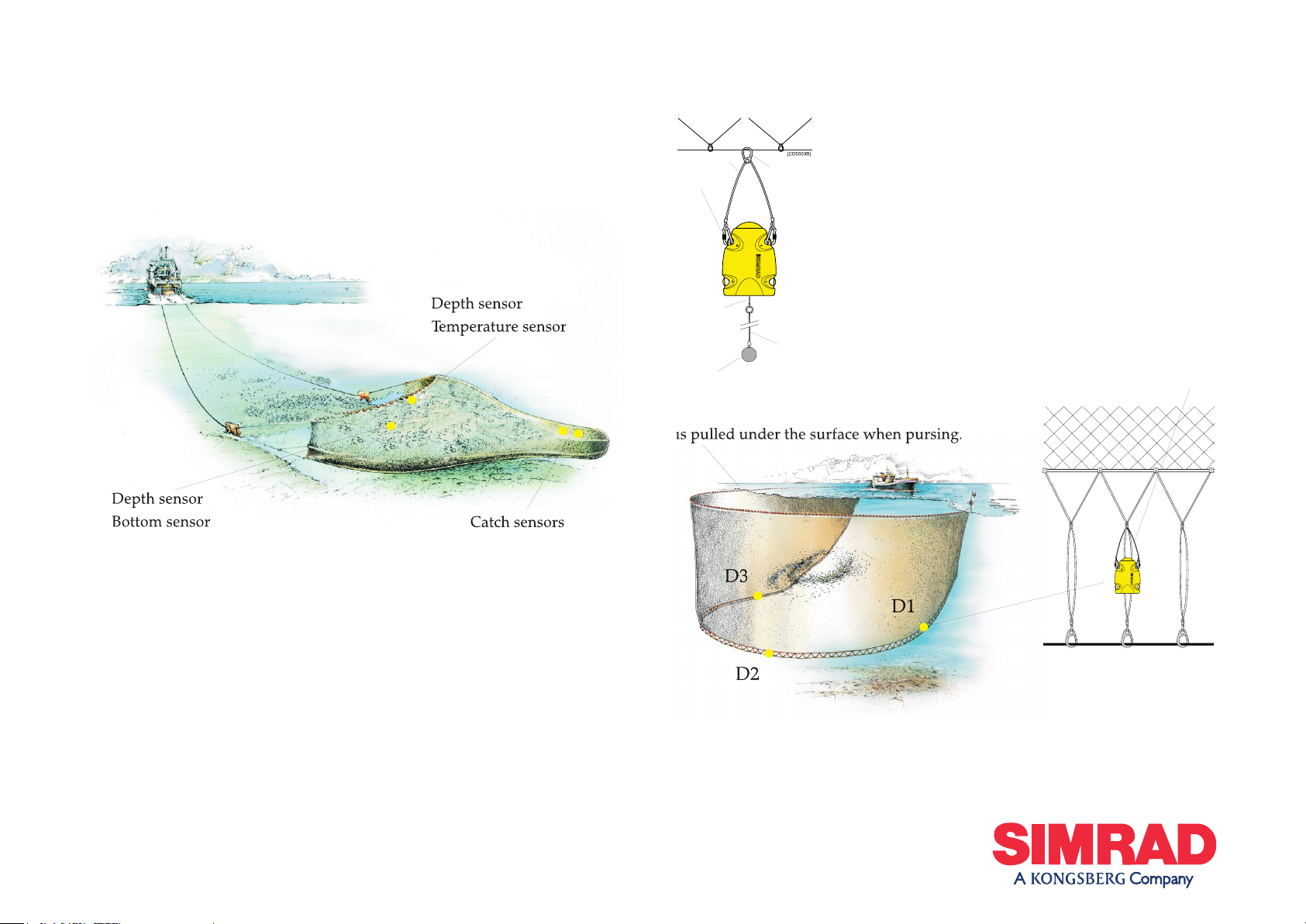
Depth sensor
Temperature sensor
Depth sensor
Bottom sensor
Monitoring
- sensors are preferably attached to the purse
wire with a purse ring or alternatively, as show here, to
the bridle. Sensors must be allowed to hang as freely as
possible so that they point vertically when pursing.
Sensors can be attached to the headwire to warn if it
is pulled under the surface when pursing.
Bottom sensors -
are attached to the purse wire using a
purse ring, wire strop and two karabiners. A weight of
approximately 4.5 kg (or another purse ring) is attached
to the sensors’ detector wire with a flexible, thin rope. The
total length of the strop, sensor, detector wire and rope
thread the weight on the ring needle (but not
around the purse wire) so that the bottom sensor will
be deployed first. The weight must hang freely and sink
clear of other gear so that it may activate the sensor when
bottom contact is made.
Weight
Detector
wire
Rope
Strop
Karabiner
Purse
ring
Page 2

cm in length that will securely hold the bottom sensor in a stable position.
2.) Bend the penetration ring for the detection wire about 30 cm below the footrope as illustrated. Attach
the bottom sensor and check that its detection wire passes through the centre of the penetration ring.
Remove the netting on the inside of the penetration ring.
3.) Attach the rubber strops so that the bottom sensor is held horizontally when towed.
torn off during fishing operations. The sensor’s detection wire must always be allowed to pass freely
through the centre of the penetration ring when it is deployed.
bottom sensors can detect bottom contact with a
precision of just a few centimeters when correct stay and
mance requires that these lengths are configured with regard
to both each other and the gear in use (the standard delivery includes a 63 cm stay and 39 cm detection chain
for use with 14 to 16 inch bobbins or rock hoppers).
the desired bottom detection distance is relative to the diameter of the rock hoppers,
bobbins or other gear in use. This relationship can be determined and precise stay and detection chain
length adjustments made as described below.
- lay the bottom sensor on an elevated surface and observe detection wire movement while simulating
bottom contact by raising the weight. Adjust the detection chain length as necessary. Tilt the weight
approximately 25°(
α
is due to drag through the water) opposite the towed direction and adjust the stay
length so that it begins to be taught. Avoid extra links at the weight ends when shorting chains.
before they transit the drum when hauling to prevent damage.
attach the sensor at the top of the cod-end, closest to where
the catch is to be monitored. As the cod-end fills the net’s mesh will
become taught and activate the catch sensor.
Attachment -
the catch sensor’s orientation toward the mother vessel is
maintained by the steel/nylon attachment rings, strops and karabiners
bent to the net. The number of mesh squares the sensor is supported
between must be restricted to avaoid unnecessary stress on the gear
when the net is filled to maximum capacity. Note that both steel
attachment rings must be located on the same side of the sensor.
is determined by the number of mesh squares separating
the two rubber strops (a larger number increases sensitivity, a smaller
reduces it). Simulate sensor activation by stretching the net’s mesh to
approximate the load generated by a full catch. Experiment accordingly
to determine the correct attachment points and then permanently
mark their locations for future reference.
are subject to heavy loading/wear; they should be
changed at regular intervals and checked before shooting. Strops with
cracks or visible signs of damage should be change immediately.
to a net with an approximate mesh size of 140
mm is illustrated below. The distance between the anchor points for
the attachment rings and rubber strops will vary according to mesh
Vessel
Karibiner and
Nylon
attachment rings,
bent to the netting
attachment rings,
bent to the netting
Rubber strop
Karabiner
Detector wires
Rock hopper,
bobbins, etc.
Attachment ring for the
stay bent securely to the
Karabiners are bent securely to the “top” of the footrope. If the bottom sensor is
attached to the wings, the length of the lashings must be adjusted so that the sensor
points toward the mother vessel when towed.
Penetration ring for
the detection wire.
Weight and stay hang
freely under the trawl.
Touch Down
Detection
wire
Detection
chain
Weight
Stay
Rock hopper
30 cm
Bottom
End link
Note 1
Note 1
Note 1:
The stay can also be attached to the steel spacer between the bobbins/rock
hopper if the footrope is held fairly stable relative to the gear.
 Loading...