

Page 1
NAC-2/NAC-3
Commissioning Manual
ENGLISH
www.bandg.com | www.simrad-yachting.com
Page 2

Page 3

Preface
Disclaimer
As Navico is continuously improving this product, we retain the
right to make changes to the product at any time which may not be
reflected in this version of the manual. Please contact your nearest
distributor if you require any further assistance.
It is the owner’s sole responsibility to install and use the equipment
in a manner that will not cause accidents, personal injury or
property damage. The user of this product is solely responsible for
observing safe boating practices.
NAVICO HOLDING AS AND ITS SUBSIDIARIES, BRANCHES AND
AFFILIATES DISCLAIM ALL LIABILITY FOR ANY USE OF THIS PRODUCT
IN A WAY THAT MAY CAUSE ACCIDENTS, DAMAGE OR THAT MAY
VIOLATE THE LAW.
Governing Language: This statement, any instruction manuals, user
guides and other information relating to the product
(Documentation) may be translated to, or has been translated from,
another language (Translation). In the event of any conflict between
any Translation of the Documentation, the English language version
of the Documentation will be the official version of the
Documentation.
This manual represents the product as at the time of printing.
Navico Holding AS and its subsidiaries, branches and affiliates
reserve the right to make changes to specifications without notice.
Trademarks
NMEA® and NMEA 2000® are registered trademarks of the National
Marine Electronics Association.
Copyright
Copyright © 2016 Navico Holding AS.
Warranty
The warranty card is supplied as a separate document.
In case of any queries, refer to the product's web site on
www.simrad-yachting.com or www.bandg.com.
Preface | NAC-2/NAC-3 Commissioning Manual
3
Page 4

Compliance statements
This equipment complies with:
• CE under EMC directive 2014/30/EU
• The requirements of level 2 devices of Radiocommunications
(Electromagnetic Compatibility) standard
The relevant Declaration of conformity is available in the product's
section on www.simrad-yachting.com or www.bandg.com.
About this manual
The manual assumes that the user has basic knowledge of
navigation, nautical terminology and practices.
Important text that requires special attention from the reader is
emphasized as follows:
Note: Used to draw the reader’s attention to a comment or
Ú
some important information.
Warning: Used when it is necessary to warn
personnel that they should proceed carefully to
prevent risk of injury and/or damage to equipment/
personnel.
Manual version
This manual is written for software version 1.0. The manual is
continually updated to match new software releases. The latest
available manual version can be downloaded from the product site
on www.simrad-yachting.com or www.bandg.com.
4
Preface | NAC-2/NAC-3 Commissioning Manual
Page 5

Contents
7 Introduction
7 NAC-2 and NAC-3 autopilot computers
7 Autopilot controllers
7 Autopilot computer setup
10 Dockside setup
10 Data source selection
10 Boat characteristics
10 Drive configuration
13 Rudder setup
16 Sea trial
16 Compass setup
17 Transition speed
18 Set rudder zero position
18 Set turn rate
18 Tuning the autopilot
23 User settings
23 Steering profile settings
24 Sailing parameters
25 Turn pattern settings
29 Installation verification
29 Checklist
29 Boat specific settings
32 Maintenance
32 Preventive maintenance
32 Checking the connectors
32 Software update
32 Resetting the autopilot computer
34 Technical specifications
34 NAC-2
35 NAC-3
Contents | NAC-2/NAC-3 Commissioning Manual
5
Page 6

37 Dimensional drawings
37 NAC-2
37 NAC-3
38 Supported data
38 NMEA 2000 PGNs
41 NMEA 0183 sentences
42 NMEA 2000 PGN description
6
Contents | NAC-2/NAC-3 Commissioning Manual
Page 7

1
Introduction
NAC-2 and NAC-3 autopilot computers
The NAC-2 and NAC-3 autopilot computers contain the electronics
needed to operate a hydraulic steering pump or mechanical drive
unit, while also interfacing with rudder feedback units and NMEA
2000 devices.
The NAC-2 is designed for boats up to 10 metres (33 feet) in length
and is suitable for low-current pumps, mechanical drive units, or
solenoid valves (8 amps continuous/16 amps peak).
The NAC-3 is designed for boats 10 metres (33 feet) or greater in
length and is rated to operate high-current pumps, mechanical
drive units, and solenoid valves (30 amps continuous/50 amps
peak).
Autopilot controllers
The NAC-2 and NAC-3 autopilot computers can be controlled by
various Simrad and B&G control units. This can be dedicated
autopilot controllers (e.g. AP44), Multifunction displays (MFDs) and
autopilot remote controllers (e.g. OP12) used in combination with
instrument systems, or any combination of the above.
Autopilot functions
NAC-2 and NAC-3 include a large range of functions, but not all
autopilot controllers have access to all options. E.g. autopilot
systems including only an autopilot remote controller (without
display unit) do not have access to turn patterns.
The user interface
The autopilot functions are presented slightly different on the
different displays.
This manual shows screen examples from both MFDs and AP44.
Autopilot computer setup
When the autopilot installation is completed, the setup of the
autopilot computer must be performed. Failure in setting up the
autopilot correctly may prohibit the autopilot from functioning
properly.
Introduction | NAC-2/NAC-3 Commissioning Manual
7
Page 8

The setup of the autopilot computer is divided in three main steps:
• Installation settings
- Including dockside and seatrial commissioning. See "Dockside
setup" on page 10 and "Sea trial" on page 16
• User adjustment of autopilot settings
- Manual fine-tuning for various operational conditions and user
preferences. See "User settings" on page 23
Note: The Installation settings can only be accessed when the
Ú
autopilot is in Standby mode. Some systems require a
dedicated physical standby key to perform installation
procedures. This key can be a key on the autopilot controller, on
an autopilot remote controller, or it can be a separate standby
key.
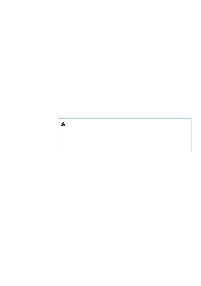
Warning: When the autopilot is delivered from
factory and any time after an autopilot reset has been
performed, the installation settings are all reset to
factory preset (default) values. A notification will be
displayed, and a complete setup has to be made.
Failure to do so correctly may prohibit the autopilot
from functioning properly!
8
Introduction | NAC-2/NAC-3 Commissioning Manual
Page 9
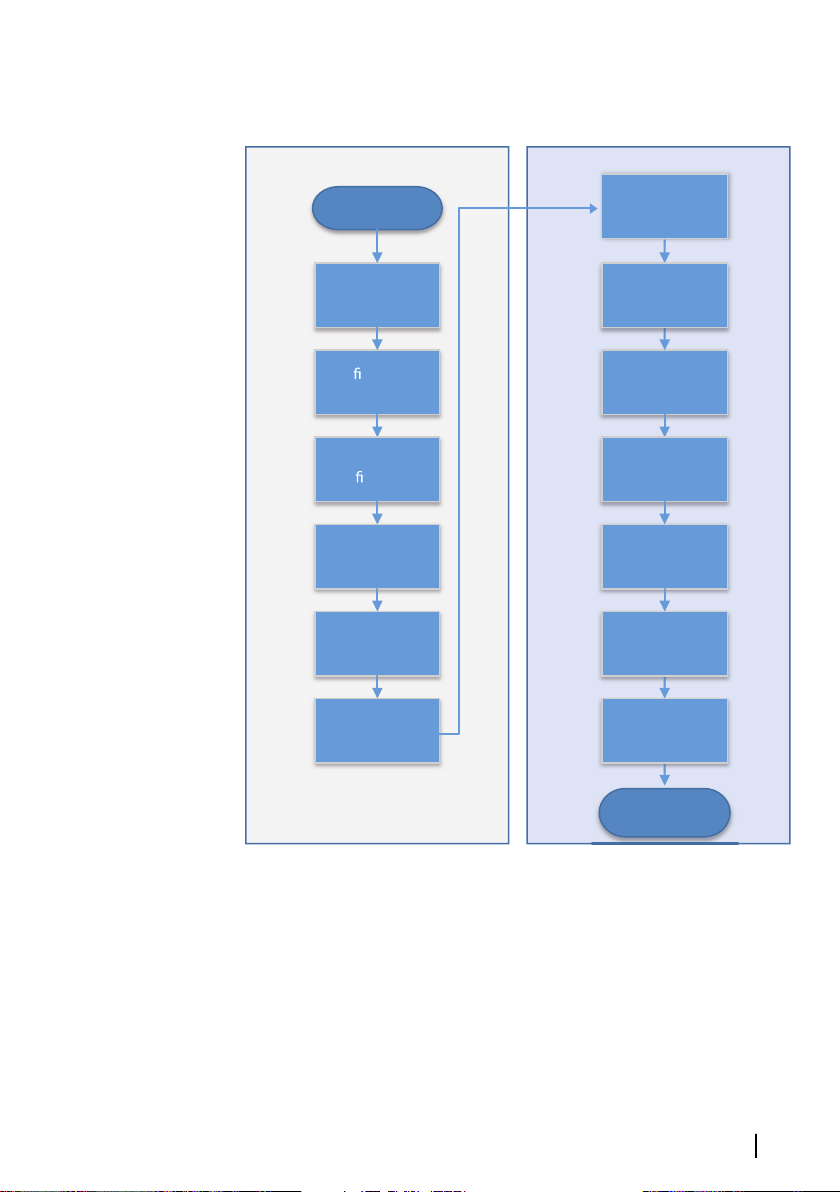
Installation setup workflow
Con gure boat
settings
Drive
con guration
Check rudder
feedback source
selection
Rudder feedback
calibration
Rudder test
Select data
sources
Set transition
speed
Set turn rate low
speed
Tune steering
parameters low
speed
Calibrate compass
Set rudder zero
Power up
Operational
autopilot system
Set turn rate high
speed
Tune steering
Dockside Sea trial
Introduction | NAC-2/NAC-3 Commissioning Manual
9
Page 10

2
Dockside setup
Data source selection
Before commencing with autopilot computer setup the data
sources must be available and configured.
Data sources selection is required on initial start-up of the system, if
any part of the network has been changed or replaced, or if an
alternative source is made available for a given data type and this
source has not been selected automatically.
You can let the system automatically select your sources, or set up
each source manually. Refer to documentation for the autopilot
controller or for the display unit for details about how to perform
the data source selection.
Boat characteristics
Boat type
Affects steering parameters as well as available autopilot features.
The following options are available:
• Sail
• Displacement
• Planing
10
Note: If the boat type is set to Sail, Virtual Rudder Feedback is
Ú
not available.
Boat length
Used by the autopilot system to calculate steering parameters.
Cruising speed
Used if no speed info is available. It is used by the autopilot system
to calculate steering parameters.
Drive configuration
The drive configuration controls how the autopilot computer
operates the steering system.
Refer to your drive unit documentation for relevant specifications.
Dockside setup | NAC-2/NAC-3 Commissioning Manual
Page 11
Control method
Used for setting the appropriate control ouput for your drive.
The following options are available:
• Solenoid
For on/off steering of hydraulic valves. Gives fixed rudder speed.
• Reversible motor
For variable speed pumps/drives.
Drive voltage
Nominal drive voltage specified for your drive unit.
• Options: 12 V and 24 V.
Note: 24 V output is only available with 24 V supply.
Ú
The setting must match the spec of the solenoids/pump/motor.
Warning: Selection of improper voltage level for your
drive unit may damage both the drive unit and the
autopilot computer even if the protection circuits are
activated.
Drive engage
Defines how the Engage output is used.
The following options are available:
• Clutch
If your drive unit/motor/pump needs clutch to engage the
actuator, it shall be connected to the "engage" output. Configure
the "Drive engage" as clutch. The clutch will be activated when
autopilot computer is controlling the rudder. In standby, the
clutch is released to allow manual steering. Check specification of
your drive unit to determine whether clutch is required.
• Auto
Output activated when autopilot computer is in Auto, NoDrift or
Navigation modes. For manual rudder control (Standby, NFU and
FU) the output is not activated. Typically used to switch between
two rudder speeds on a continuous running pump, used when
Dockside setup | NAC-2/NAC-3 Commissioning Manual
11
Page 12

different rudder speeds are required for automatic and Followup/Non-Follow-up steering.
Minimum rudder
Some boats may have a tendency to not respond to small rudder
commands around the “course keeping” position because of a small
rudder, whirls/disturbance of the water-stream passing the rudder,
or it is a single nozzle water jet boat. By increasing the Minimum
rudder parameter you may improve the course keeping
performance on some boats. However, this will increase the rudder
activity.
Note: Only set a value for minimum rudder if it proves to give a
Ú
better course keeping performance in calm sea. It should be set
after the autopilot steering parameters have been optimised/
tuned.
Rudder deadband
Prevents the rudder from hunting induced by mechanical play in
the steering gear or rudder.
The following options are available
• Auto
(Recommended).
The rudder deadband is adaptive and is continuously operative. It
will also optimize the deadband to the pressure on the rudder
12
• Manual
If the Auto setting doesn’t perform properly due to extreme
rudder speed and/or overshoot, it can be adjusted manually. Can
also be used to reduce the rudder activity. Rudder commands
smaller than the size of the dead band will be ignored
Find the lowest possible value that will prevent the rudder from
continuous hunting. A wide deadband will cause inaccurate
steering. It is recommended to check rudder stability in AUTO mode
at cruising speed to get pressure on the rudder. (Slight hunting
observed dockside may disappear at cruising speed.)
Dockside setup | NAC-2/NAC-3 Commissioning Manual
Page 13
Rudder setup
Warning: During the rudder calibration and test the
autopilot computer issues a series of rudder
commands. Stand clear of the helm and do not
attempt to take manual control of the rudder during
this test!
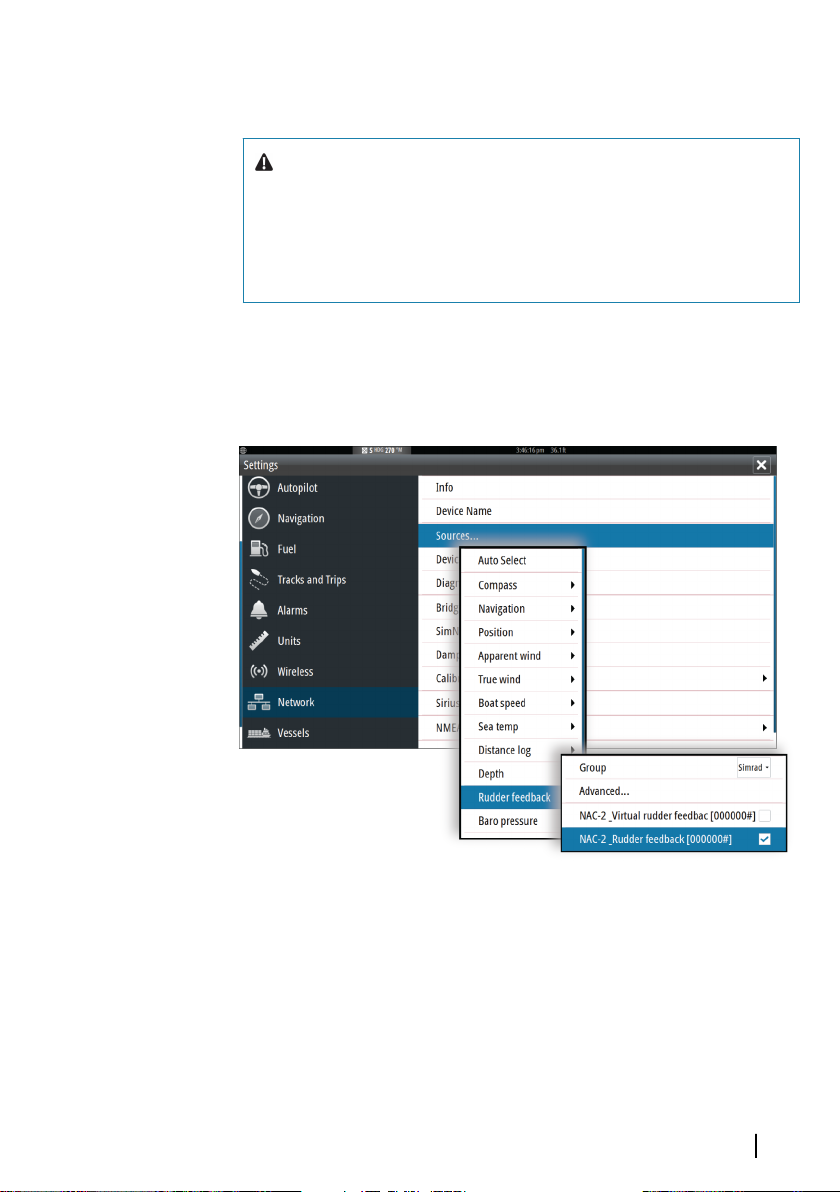
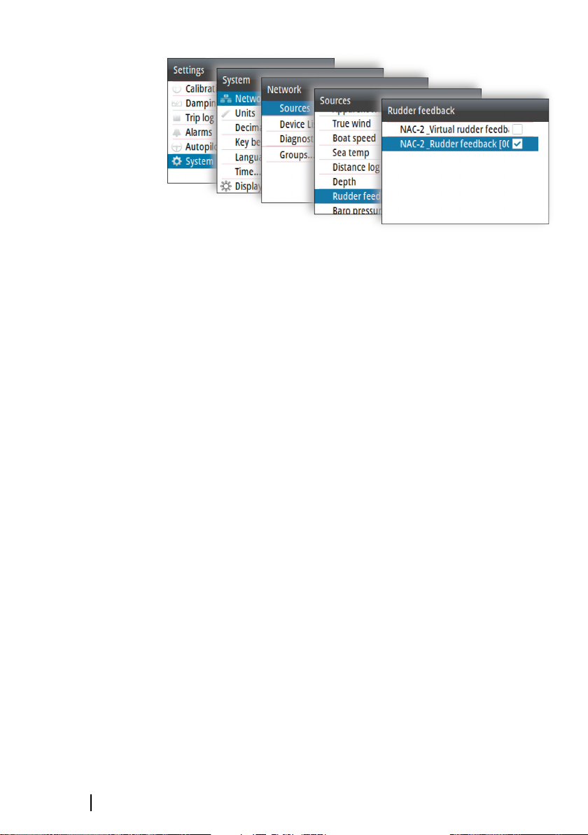
Rudder source
The correct rudder source has to be selected before the rudder
feedback calibration can be performed.
Rudder source selection, MFDs
Dockside setup | NAC-2/NAC-3 Commissioning Manual
13
Page 14
Rudder source selection, AP44
Note: Virtual Rudder Feedback (VRF) should only be used if no
Ú
rudder feedback is available. Installing a feedback unit will
enhance the performance of an autopilot and provide an
accurate rudder angle indicator on the autopilot display.
Note: VRF is not available if boat type is set to Sail.
Ú
Rudder feedback calibration
Note: Only available if you have a rudder feedback unit installed
Ú
and selected as rudder source.
The rudder feedback calibration determines the rudder feedback's
direction.
• Follow the on-screen guided steps until the rudder calibration is
completed.
Rudder test
This rudder test verifies the drive direction. It detects minimum
power to drive the rudder and reduces the rudder speed if it
exceeds the maximum preferred speed for autopilot operation.
Note: If the boat uses power assisted steering, it is important
Ú
that the engine or electric motor used to enable the power
assist steering is turned on prior to this test.
14
• Run the rudder test as described in the on-screen instructions
- Rudder should make a small movement within 10 seconds,
then follow up with travelling both directions
Dockside setup | NAC-2/NAC-3 Commissioning Manual
Page 15

Failure to complete test will result in an alarm.
VRF calibration
Note: Only available if the rudder source is set to a virtual
Ú
rudder feedback.
VRF calibration determines the direction of rudder movement, the
minimum output required to move the rudder and the voltage to
rudder speed ratio.
To perform the VRF calibration you must be able to view the
movement of the rudder.
• Follow the on-screen guided steps until the VRF calibration is
completed.
Dockside setup | NAC-2/NAC-3 Commissioning Manual
15
Page 16
3
Sea trial
A seatrial can only be performed after the dockside settings are
completed.
Note: The seatrial must always be performed in calm
Ú
conditions, in open waters and at a safe distance from other
traffic!
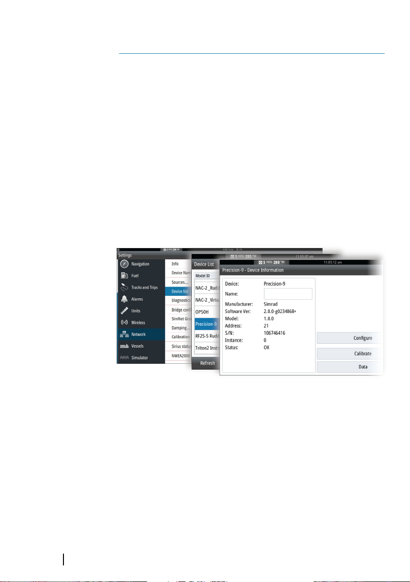
Compass setup
To achieve the best possible performance, the compass should be
calibrated, and any offsets should be compensated for.
The setup needs to be done from an appropriate display unit.
Depending on the unit, access to the compass setup is available
from the compass’s device dialog, or from a dedicated Calibration
option in the unit’s Settings menu.
16
Device dialog, MFDs
Sea trial | NAC-2/NAC-3 Commissioning Manual
Page 17

Calibration option, AP44
Note: The setup of the compass should be done in calm sea
Ú
conditions and with minimal wind and current to obtain good
results. Ensure that there is enough open water around the
vessel to make a full turn.
Refer to your heading sensor's documentation for further details for
your unit.
Transition speed
The transition speed is the speed at which the system automatically
changes between Low speed and High speed steering profiles.
The steering profiles are used to accommodate the boats' tendency
to exhibit different steering characteristics at different speeds. You
may also have different preferences about the steering performance
of your boat required at low and high speeds.
On power boats it is recommended that you set a value that
represents the speed where the boat's steering characteristics
change. For instance the planing threshold (recommended), or at
the speed you want the autopilot to change behavior.
There is a 2 knots hysteresis to prevent oscillation of high/low
settings when the vessel is travelling at or near the transition speed.
Example
The transition speed is set to 9 knots.
• The system changes from Low profile to High profile when the
speed increases to 10 knots (= Transition speed plus 1 knot)
• The system changes from High profile to Low profile when the
speed decreases to 8 knots (= Transition speed minus 1 knot)
Sea trial | NAC-2/NAC-3 Commissioning Manual
17
Page 18

The active profile ('Low' or 'High') is shown in the autopilot page
(e.g. AP44) and in the autopilot pop-up (MFDs):
AP44 page MFD Autopilot pop-up
Set rudder zero position
Used to correct the rudder zero position found during dockside
commissioning if the boat needs a small rudder offset in order to
steer straight.
Note: Setting rudder zero position should always be done in
Ú
calm conditions, where steering is not affected by wind and/or
current.
• Bring the rudder to the position where the boat steers straight,
then activate the Set rudder zero option to save the rudder
zero parameter.
Note: On dual engine boats, verify that the engine RPM is equal
Ú
on both engines so that the thrust from both propellers is
equal. Otherwise, the zero rudder position might be set wrong.
18
Set turn rate
Used for setting the preferred turn rate of the boat.
• Bring the boat into a turn with the preferred safe and
comfortable turn rate, then activate the Set turn rate option to
save the turn rate parameters.
Note: The captured turn rate will be stored in the active
Ú
steering profile. This setting must therefore be repeated for
each steering profile.
Tuning the autopilot
Note: Tuning of the autopilot must be done separately for low
Ú
and high speed profiles.
Sea trial | NAC-2/NAC-3 Commissioning Manual
Page 19

Both Autotune and manual tuning should be performed in
calm or moderate sea conditions.
Providing you have entered correct vessel type, length and cruising
speed, you may not have to perform further manual or automatic
tuning.
Proceed as follows to verify satisfactorily steering:
1. Stabilize the vessel on a heading, and then select AUTO mode
2. Observe course keeping and rudder commands
- The autopilot should keep the vessel on the set heading
within an average of +/-1 degree, providing calm sea and
wind
3. Make some small and bigger heading changes to port and
starboard and observe how the vessel settles on the new
heading
- The vessel should have a minimum of overshoot. See "Rudder
gain" on page 21 and "Counter rudder" on page 21.
If the autopilot is not keeping the heading satisfactorily or not
making the turns satisfactorily, you may now either try the Autotune
function or go directly to manual tuning.
Note: If the vessel is more than approximately 30 m/100 ft or
Ú
has a very high cruising speed it may be unpractical to perform
Autotune. It is then suggested to proceed with manual tuning.
Autotuning
When performing an autotune, the vessel will automatically be
taken through a number of S-turns. Based on the vessel behavior,
the autopilot will automatically set the most important steering
parameters (Rudder gain and Counter rudder).
• Stabilize the vessel on a heading and set the speed as close to
cruising speed as possible, then activate the Autotune function.
- The autopilot will now switch to AUTO mode and take control
of the vessel.
Note: Autotuning can be stopped at any time by pressing the
Ú
STBY key on the autopilot controller.
The autotuning takes approximately 3 minutes to complete. When
completed the autopilot automatically switches to Standby mode,
and the rudder must be controlled manually.
Sea trial | NAC-2/NAC-3 Commissioning Manual
19
Page 20

Note: All parameters that are set during autotuning can be
Ú
manually adjusted. For optimal steering performance it is
recommended to manually adjust the steering parameters after
running the autotune.
Manual tuning
Rudder gain and Counter rudder can be manually adjusted.
• Stabilize the vessel on a heading and set the speed in the middle
of the profile range (well clear of the transition speed) to avoid
profile switching during tuning. Then activate the Rudder gain
option. Adjust the value according to the descriptions below.
• If required, adjust slightly the Counter rudder option.
20
Tuning parameters, MFDs
Sea trial | NAC-2/NAC-3 Commissioning Manual
Page 21

Tuning parameters, AP44
A
B
Rudder gain
This parameter determines the ratio between commanded rudder
and the heading error. The higher rudder gain value the more
rudder is applied. If the value is too small it will take a long time to
compensate for a heading error, and the autopilot will fail to keep a
steady course. If the value is set too high the overshoot will increase
and the steering will be unstable.
A The value is set too high. Steering becomes unstable and
often the overshoot will increase
B The value is set too low. It will take a long time to
compensate for a heading error, and the autopilot will fail to
keep a steady course
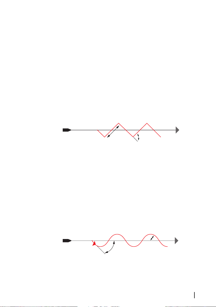
Counter rudder
Counter rudder is the amount of counteracting (opposite) rudder
applied to stop the turn at the end of a major course change. The
settings depend on vessel’s characteristics, inertia, hull shape and
rudder efficiency.
Sea trial | NAC-2/NAC-3 Commissioning Manual
21
Page 22

• If the vessel has good dynamic stability, a relatively small value
A B C
will be sufficient
• An unstable vessel will require high value
• The greater the vessel’s inertia, the greater value will be required
Increasing counter rudder value may result in some higher rudder
activity also when steering a straight course, particularly in high
waves.
The best way of checking the value of the Counter rudder setting is
when making turns. The figures illustrate the effects of various
Counter Rudder settings.
A Counter rudder value too low; overshoot response
B Counter rudder value is too high; sluggish and creeping
response
C Correct setting of Counter rudder; ideal response
Perform various course changes and observe how the boat settles
on the new heading. Start with small changes, 10-20 degrees, and
proceed with bigger changes, 60-90 degrees. Adjust Counter rudder
value to obtain best possible response as in illustration C.
Note: As many boats turns differently to port versus starboard
Ú
(due to propeller rotation direction), do the course changes in
both directions. You may end up with a compromise setting of
Counter rudder that gives a little overshoot to one side and a
bit creeping response to the other.
22
Sea trial | NAC-2/NAC-3 Commissioning Manual
Page 23

4
User settings
The user settings can be configured differently between the
different profiles, depending on boat steering characteristics and
user preferences.
Steering profile settings
The NAC-2 and NAC-3 include two steering profiles (High and Low),
used for high and low boat speed.
The initial parameters are automatically assigned when you select
your vessel type. During the seatrial the parameters will be tuned for
optimized steering performance. See "Tuning the autopilot" on page 18.
The options listed in the next pages are available for both High and
Low speed profiles.
For Rudder gain and Counter rudder, see "Rudder gain" on page 21 and
"Counter rudder" on page 21.
Turn rate
Used for manually setting the turn rate defined during seatrials (Set
turn rate option).
Autotrim
Controls how fast the autopilot will apply rudder to compensate for
a constant heading offset, e.g. when external forces such as wind or
current affects the heading. Lower autotrim will give faster
elimination of a constant heading offset
Note: In VRF mode this parameter controls the time constant of
Ú
the rudder estimate. A lower value makes the rudder estimate
faster, i.e. that it will more quickly catch up with the boat's
movements.
Init rudder
Defines how the system moves the rudder when switching from
power steering to an automatic mode.
The following options are available:
• Center
Moves the rudder to zero position
User settings | NAC-2/NAC-3 Commissioning Manual
23
Page 24

• Actual
Maintains the rudder angle, and assumes that the current rudder
angle is the trim required to maintain a steady heading.
Rudder limit
Determines the dynamic range of the rudder before its movement
is restricted and alarm is triggered. Typical usage is to limit the
amount of rudder action caused by yawing in following sea.
Note: Rudder limit is not a hard limitation of the rudder range,
Ú
only around the current setpoint.
This Rudder limit does not affect Non-Follow-up or Follow Up
steering.
Off heading limit angle
Sets the limit for the off heading alarm.
When the alarm option is activated an alarm occurs when the actual
heading deviates from the set heading more than the selected limit.
Track response
Defines how aggressively the autopilot should steer towards the
active route's leg.
24
Track approach angle
This setting is a limit to prevent approaching the track too steeply.
Approaching the track at shallower angles is permitted depending
on the cross track distance (XTD) and track response setting.
This setting is used both when you start navigating and whenever
the autopilot is working the boat towards the route.
Course change confirm angle
Defines the limit for automatic course change to next waypoint in a
route when the autopilot is following a route (NAV mode).
If the course change is greater than this set limit, you are prompted
to verify that the upcoming course change is acceptable.
Sailing parameters
Note: Only available if the boat type is set to SAIL.
Ú
User settings | NAC-2/NAC-3 Commissioning Manual
Page 25

Wind mode
Select what wind angle the autopilot will steer towards.
The following options are available:
• Auto
If True Wind Angle (TWA) is <70º: Wind mode will steer towards
Apparant Wind Angle (AWA)
If TWA is ≥70º: Wind mode will steer towards TWA
• Apparent
Steers towards AWA
• True
Steers towards TWA
Tack time
Controls how fast the autopilot tacks in wind mode.
Tack angle
Controls the angle that the boat will tack to in AUTO mode.
Manual speed
If neither boat speed nor SOG data are available and/or deemed
unreliable, a manual value for speed can be entered and used by
the autopilot to aid steering calculations.
Turn pattern settings
The autopilot computer supports a number of automatic turn
steering features when the autopilot is in AUTO mode.
Note: Turn pattern steering is not available if the boat type is
Ú
set to Sail.
All turn patters, except the U-turn, have associated turn pattern
settings. Depending on the autopilot controller these turn pattern
settings can be adjusted before you start the turn or during the turn.
User settings | NAC-2/NAC-3 Commissioning Manual
25
Page 26

Turn pattern settings, MFD
Turn pattern settings, AP44
Note: Not all autopilot controllers include turn pattern steering.
Ú
Refer to your autopilot controller for more information.
C-turn (Continuous turn)
Steers the vessel in a circle.
• Turn variable:
- Rate of turn. Increasing the value makes the vessel turn a
smaller circle.
26
U-turn
Changes the current set heading to be 180° in the opposite
direction.
User settings | NAC-2/NAC-3 Commissioning Manual
Page 27
Spiral turn
B A
D
C
Makes the vessel turn in a spiral with a decreasing or increasing
radius.
• Turn variables:
- Initial radius
- Change/turn. If this value is set to zero, the boat will turn in a
circle. Negative values indicate decreasing radius while positive
values indicate increasing radius.
Zigzag turn
Steers the vessel in a zigzag pattern.
• Turn variables:
- Course change (A)
- Leg distance (B)
Square turn
Makes the vessel automatically turn 90° after having travelled a
defined leg distance.
• Turn variable:
- Leg distance
Lazy-S turn
Makes the vessel yaw around the main heading.
• Turn variables:
- Course change (C)
- Turn radius (D)
Depth contour tracking (DCT)
Makes the autopilot follow a depth contour.
User settings | NAC-2/NAC-3 Commissioning Manual
27
Page 28

Note: DCT turn pattern is only available if the system has a valid
Ú
depth input.
• Turn variables:
- Depth gain. This parameter determines the ratio between
commanded rudder and the deviation from the selected depth
contour. The higher depth gain value the more rudder is
applied. If the value is too small it will take a long time to
compensate for drifting off the set depth contour, and the
autopilot will fail to keep the boat on the selected depth. If the
value is set too high the overshoot will increase and the
steering will be unstable.
- CCA. The CCA is an angle that is added to or subtracted from
the set course. With this parameter you can make the boat yaw
around the reference depth with lazy-s movements. The larger
the CCA the bigger yawing will be allowed. If the CCA is set to
zero there is no S-ing.
- Ref. depth. This is the reference depth for the DCT function.
When DCT is initiated the autopilot reads the current depth
and set this as the reference depth. The reference depth can be
changed when the function is running.
Note: If depth data is lost during DCT the autopilot will
Ú
automatically switch to AUTO mode.
It is recommended to turn ON the AP Depth Data Missing alarm
when using DCT. When this alarm is activated an alarm will be
raised if the depth data is lost during DCT.
28
User settings | NAC-2/NAC-3 Commissioning Manual
Page 29

5
Installation verification
When all units in the autopilot system are installed, external
equipment connected and the software configured according to
the previous chapters, the installation should be verified according
to the checklist. The boat specific settings should be noted down in
the relevant tables included this chapter.
Checklist
Description Reference
Units mounted and secured
according to instructions
Network powered and
terminated according to
instructions
Sources selected
Vessel configured "Boat characteristics" on page 10
Drive units configured and
calibrated
Compass calibrated "Compass setup" on page 16
Seatrial completed (manual or
autotune)
Installation instructions for the
units
Wiring instructions for the units
Autopilot control unit
documentation
"Drive configuration" on page 10
"Sea trial" on page 16
Boat specific settings
Boat
Settings
Boat type
Boat length
Cruising speed
Transition sped
Installation verification | NAC-2/NAC-3 Commissioning Manual
29
Page 30

Drives
Settings
Drive type
Drive control method
Nominal drive voltage
Drive engage
Minimum rudder
Rudder deadband
Manual deadband
Minimum output
Maximum output
Sailing parameters
Settings
Wind mode
Tack time
Tack angle
Manual speed
30
Steering profiles
Settings Low Speed High Speed
Turn Rate
Rudder gain
Counter rudder
Autotrim
Init rudder
Rudder limit
Installation verification | NAC-2/NAC-3 Commissioning Manual
Page 31

Settings Low Speed High Speed
Off heading limit
Track response
Track approach
angle
Course change
confirm angle
Turn Pattern settings
Settings
Continuous
Rate of turn
Spiral
Initial radius
Change/turn
Zigzag
Course change
Leg distance
Square
Leg distance
Lazy-S
Course change
Turn radius
Depth contour
Depth gain
CCA
Installation verification | NAC-2/NAC-3 Commissioning Manual
31
Page 32
6
Maintenance
Preventive maintenance
The unit does not contain any field serviceable components.
Therefore, the operator is required to perform only a very limited
amount of preventative maintenance.
Checking the connectors
The connectors should be checked by visual inspection only.
Push the connector plugs into the connector. If the connector plugs
are equipped with a lock, ensure that it is in the correct position.
Software update
You can update the software for the autopilot computer from a
display unit connected to the network.
You can check the autopilot computer's software version from the
display unit's Device list.
The latest software is available for download from the product
website on www.simrad-yachting and www.bandg.com.
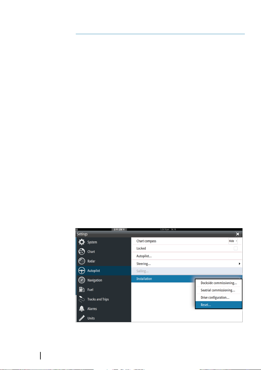
Resetting the autopilot computer
You can reset the autopilot to factory default settings.
32
Reset autopilot computer, MFDs
Maintenance | NAC-2/NAC-3 Commissioning Manual
Page 33

Reset autopilot computer, AP44
The first time the autopilot computer is started after reset, it will run
through the automatic setup-procedure.
Note: Unless you need to clear all values set during the
Ú
installation set-up procedure, you should not perform a reset of
the autopilot computer.
Maintenance | NAC-2/NAC-3 Commissioning Manual
33
Page 34

Technical specifications
NAC-2
7
Approvals
Compliance EMC directive 2014/30/EU
Electrical
Supply voltage 9-31.2 V DC
Power consumption - Max 500 W
Power consumption - Typical As required to drive rudder
actuator. See pump/motor
power ratings
Recommended fuse rating 20 A
Environmental
Operating temperature -25°C to +55°C (-13°F to 131°F)
Storage temperature -30°C to +70°C (-22°F to 158°F)
Waterproof rating IPx5
Humidity 100%
Shock and vibration Acc to EN60945
Connectivity
NMEA 2000 1 Micro-C port, 1 LEN
Drive 12/24 V DC, min 10 mA, max 3 A
Rudder Feedback Variable voltage/resistive 0‐5 V
NMEA 2000 PGNs See "NMEA 2000 PGNs" on page 38
Physical
Dimensions See "NAC-2" on page 37
Weight 0.6 kg (1.3 lbs)
Compass Safe Distance 500 mm (20 inches)
Warranty 2 years
34
Technical specifications | NAC-2/NAC-3 Commissioning Manual
Page 35

NAC-3
Approvals
Compliance EMC directive 2014/30/EU
Electrical
Supply voltage 12/24 V DC +/- 10-30%
Power consumption - Max 750 W
Power consumption - Typical As required to drive rudder
actuator. See pump/motor
power ratings
Recommended fuse rating 30 A
Environmental
Operating temperature -25°C - +55°C (-13°F - 131°F)
Storage temperature -30° - +70°C (-22°F - 158°F)
Waterproof rating IPx5
Humidity 100%
Shock and vibration Acc to EN60945
Connectivity
NMEA 2000 1 Micro-C port, 1 LEN
NMEA 0183 1 port IN/OUT. 4.8, 9.6,
19.2 & 38.4 kbaud
Drive • Reversible motor control
of rudder.
Max continuous load 30
A, peak 50 A for 1s
or
• On/off
solenoid control of rudder.
12/24 V DC,
common, load range 10
mA to 10 A, off current <1 mA
Engage Output for bypass/clutch. 12/24
V DC, min 10 mA, max 3 A
Technical specifications | NAC-2/NAC-3 Commissioning Manual
35
Page 36

Rudder Rudder angle, frequency input.
15 V, 1.4 to 5 kHz, resol. 20 Hz/°
Remote • Input: External open/
close contact for remote
controller
• Output: High/Low mode
indicator signal
Mode External open/close
or pulse contact for autopilot
disengage
Alarm External alarm output for
buzzer/relay. Max 100 mA,
voltage level as local supply
Physical
Dimensions See "NAC-3" on page 37
Weight 0.7 kg (1.6 lbs)
Compass Safe Distance 500 mm (20 inches)
Warranty 2 years
36
Technical specifications | NAC-2/NAC-3 Commissioning Manual
Page 37

204.0 mm (8.1”)
183.0 mm (7.2”)
57.0 mm (2.2”)
180.0 mm (7.1”)
190.0 mm (7.5”)
169.0 mm (6.63”)
91.0 mm (3.6”)
211.0 mm (8.31”)
195.0 mm (7.68”)
65.5 mm (2.58”)
92.0 mm (3.62”)
196.0 mm (7.72”)
8
Dimensional drawings
NAC-2
NAC-3
Dimensional drawings | NAC-2/NAC-3 Commissioning Manual
37
Page 38

Supported data
NMEA 2000 PGNs
9
NAC-2
• MD: Main Device
• RF: Rudder Feedback
• VRF: Virtual Rudder Feedback
MD RF VRF
TX RX TX RX TX RX
59392 x x x x x x
59904 x x x x x x
60160 x x x x x x
60416 x x x x x x
60928 x x x x x x
65240 x x x
65305 x x
65323 x x
65341 x
65342 x x
126208 x x x x x x
126996 x x x x
127237 x x
127245 x x x x
127250 x
127251 x
127257 x
127258 x
128259 x
128267 x
129025 x
38
Supported data | NAC-2/NAC-3 Commissioning Manual
Page 39

MD RF VRF
TX RX TX RX TX RX
129026 x
129029 x
129283 x
129284 x
130306 x
130577 x
130821 x
130840 x x
130845 x x x x
130846 x x x x
130850 x x x x
130851 x x x x
130856 x x
130860 x
Supported data | NAC-2/NAC-3 Commissioning Manual
39
Page 40

NAC-3
• MD: Main Device
• RF: Rudder Feedback
• VRF: Virtual Rudder Feedback
• NM: NMEA 0183
• CD: Control Device
MD RF VRF NM CD
TX RX TX RX TX RX TX RX TX RX
59392 x x x x x x x x x x
59904 x x x x x x x x x x
60160 x x x x x x x x x x
60416 x x x x x x x x x x
60928 x x x x x x x x x x
65240 x x x x x
65305 x x x
65323 x x
65341 x
65342 x x
126208 x x x x x x x x x x
126996 x x x x x x
127237 x x x
127245 x x x x x x
127250 x x
127251 x x
127257 x x
127258 x x
128259 x x
128267 x x
129025 x x
129026 x x
129029 x x
40
Supported data | NAC-2/NAC-3 Commissioning Manual
Page 41

MD RF VRF NM CD
TX RX TX RX TX RX TX RX TX RX
129283 x x
129284 x x
130306 x x
130577 x
130821 x
130840 x x
130845 x x x x x x
130846 x x x x x x
130850 x x x x x
130851 x x x x x
130856 x x
130860 x
NMEA 0183 sentences
In Out NMEA 2000 PGN
AAM x 129284
ACK x 130850
129283
APB x
BOD x 129284
BWC x 129284
DPT x 128267
GGA x
GLL x
HDG x 10* 127250
Supported data | NAC-2/NAC-3 Commissioning Manual
129284
129285
129025
129029
129025
129029
41
Page 42

In Out NMEA 2000 PGN
HDT x 10** 127250
HSC x 127237
129025
RMA x
RMB x
RMC x
ROT x 127251
RSA 5 127245
THS x 127250
VBW x 128259
VHW x
VLW x 129026
VTG x 129026
ZDA x 129033
129026
127258
129283
129284
127258
129025
129026
129033
127250
128259
42
* When magnetic heading source.
** When true heading source.
NMEA 2000 PGN description
59392 ISO Acknowledgement
59904 ISO Request
60160 ISO Transport protocol, Data transfer
60416 ISO Transport protocol, Connection management, RTS
group function
60928 ISO Address claim
65240 ISO Commanded address
Supported data | NAC-2/NAC-3 Commissioning Manual
Page 43

126208 ISO Command group function
126996 Product information
127237 Heading/Track control
127245 Rudder
127250 Vessel heading
127251 Rate of turn
127257 Attitude
127258 Magnetic variation
128259 Speed, Water referenced
128267 Water depth
129025 Position, Rapid update
129026 COG & SOG, Rapid update
129029 GNSS Position data
129283 Cross Track Error
129284 Navigation data
129283 Cross Track Error
129284 Navigation data
130306 Wind data
130577 Direction data
Supported data | NAC-2/NAC-3 Commissioning Manual
43
Page 44

44
Supported data | NAC-2/NAC-3 Commissioning Manual
Page 45

Index
A
About
NAC-2 and NAC-3 7
User interface 7
Autopilot
Autotuning 19
Controllers 7
Functions 7
Manual tuning 20
Reset 32
Setup 7
Tuning 18
B
Boat
Cruising speed 10
Length 10
Transition speed 17
turn rate 18
Type 10
C
Characteristics
Boat 10
Checklist
Boat characteristic
settings 29
Boat specific settings 29
Description
Reference 29
Drive Settings 30
Installation verification 29
Sailing parameters 30
Steering profile settings 30
Turn pattern settings 31
Commissioning
Sea Trial 16
Compliance
Compatibility standard 4
D
Data source selection 10
Drawings
NAC-2 Dimensions 37
NAC-3 dimensions 37
Drive
Configuration 10
Engage, Clutch, Auto 11
Settings, Solenoid,
Reversible motor 11
Voltage 11
F
Factory default settings 32
I
Installation setup workflow 9
M
Manual
About 4
Software, Version,
download 4
N
NMEA 0183 sentences 41
NMEA 2000 PGNs 38, 40
NMEA 2000
PGN description 42
R
Rudder
Counter values 21
deadband, Auto,
Manual 12
Page 46

feedback, calibration 14
Gain, ratio 21
Init, center, actual 23
Limit 24
minimum, activity 12
setup 13
source, VRF 13
Test 14
VRF, calibration 15
Zero position 18
S
Settings
Autotrim 23
Off heading limit angle 24
Sea trial 16
Steering profiles 23
Track response 24
Turn Rate 23
User 23
Setting
Course change confirm
angle, NAV mode 24
Manual speed 25
Sailing parameters 24
Tack angle 25
Tack time 25
Track approach angle 24
Turn patterns 25
Wind mode
Auto
Apparent
True 25
Setup
Compass, Device dialog,
Calibration option 16
Dockside 10
Supported data
NMEA 0183 sentences 41
NMEA 2000 PGNs NAC-3 40
NMEA 2000 PGNs,
NAC-2 38
T
Technical Specifications
NAC-2
Warranty 34, 35
NAC-3
Turn Patterns
C-turn 26
Depth countour tracking,
depth gain, CCA 27
Lazy-S turn 27
Spiral turn 27
Square turn 27
U-turn 26
Zigzag turn 27
U
Unit
Checking the
connectors 32
Preventive
maintenance 32
Update
Software, NAC-2 and
NAC-3 32
Page 47

Page 48

*988-11233-001*
 Loading...