

Simrad MX521,MX521A,MX521B User Manual

www.simrad-yachting.com A brand by Navico - Leader in Marine Electronics
Manual
Simrad MX521/MX521A/MX521B
GPS/DGPS Sensor
English


Manual
Simrad MX521/MX521A/MX521B
GPS/DGPS Sensor
English
To the best of our knowledge, the content in this
publication was correct at the time of printing.
As we are continuously improving our products we
retain the right to make changes to the product and
the documentation at any time. Updated manuals are
available from our website www.navico.com/commercial
or www.simrad-yachting.com, and are free to download.
© Copyright 2016 by Navico Holding AS.
Document no: 727052
Revision: C
Date: July 2016
The original language for this document is English. In the
event of any discrepancy between translated versions
and the English version of this document, the English
document will be the official version.

2 | Simrad MX521/MX521A/MX521B
IMPORTANT NOTICE!
THE MX521 GPS/DGPS SENSOR IS AN AID TO
NAVIGATION ONLY. Under no circumstances should
it be used in lieu of authorized government charts.
Its accuracy can be affected by many factors such
as equipment defects, environmental conditions, or
improper operation. The user is responsible for safe
navigation of the vessel. This includes consulting
authorized government charts and exercising common
prudence and navigational judgement at all times.
Disclaimer
As Navico is continuously improving this product, we
retain the right to make changes to the product at any
time which may not be reflected in this version of the
manual. Please contact your nearest distributor if you
require any further assistance.
It is the owner’s sole responsibility to install and use the
equipment in a manner that will not cause accidents,
personal injury or property damage. The user of this
product is solely responsible for observing safe boating
practices.
NAVICO HOLDING AS AND ITS SUBSIDIARIES,
BRANCHES AND AFFILIATES DISCLAIM ALL LIABILITY
FOR ANY USE OF THIS PRODUCT IN A WAY THAT MAY
CAUSE ACCIDENTS, DAMAGE OR THAT MAY VIOLATE THE
LAW.
Governing Language: This statement, any instruction
manuals, user guides and other information relating
to the product (Documentation) may be translated
to, or has been translated from, another language
(Translation). In the event of any conflict between any
Translation of the Documentation, the English language
version of the Documentation will be the official version
of the Documentation.
This manual represents the product as at the time of
printing. Navico Holding AS and its subsidiaries, branches
and affiliates reserve the right to make changes to
specifications without notice.

Simrad MX521/MX521A/MX521B | 3
Copyright
Copyright © 2016 Navico Holding AS.
Warranty
The warranty card is supplied as a separate document.
In case of any queries, refer to the our website:
www.navico.com/commercial or
www.simrad-yachting.com

4 | Simrad MX521/MX521A/MX521B
Contents
1 General ....................................................... 6
Supplied Equipment ......................................7
2 Operation ................................................... 8
General .......................................................8
Satellite Based Augmentation System (SBAS) ...8
Receiver Autonomous Integrity Monitoring
(RAIM) ........................................................9
GLONASS Overview (MX521B only) .......... 9
Space Segment ..................................... 9
GPS and GLONASS .............................. 10
3 Installation ............................................... 11
MX521 Antenna Mounting Guidelines ............. 11
MX521 Connector ........................................ 12
Antenna Mounting ....................................... 13
Bracket Mount .................................... 13
Surface Mount .................................... 13
Antenna Cable Selection .............................. 15
Power Requirement ..................................... 16
Antenna Cable Assembly .............................. 16
MX521 Connector Conguration .................... 17
Data Interface to MX420/2 or MK12 CDU ........ 18
Data Interface to MX420/8 or MX420/AIS CDU 19
Data Interface to PC or Other Navigation
Systems .................................................... 20
MX521 Programming Cable ........................... 21
Data Interface to MX5xx CDU ....................... 22

Simrad MX521/MX521A/MX521B | 5
Data Interface to MX61x Junction Box ............ 23
4 Specications ........................................... 25
GPS Receiver ..................................... 25
Beacon Receiver (MX521A DGPS model
only) ................................................. 25
MX521B D/GNSS Receiver .................... 27
5 Data Output .............................................. 31
NMEA 0183 Data Output Sentences ....... 31
List of abbreviations ............................ 37

General | 6
1 General
This manual describes the operation and installation of
the MX521 antenna sensor.
They were designed to work either interactively with MX
Control and Display Unit (MX CDU) or as a stand-alone
positioning device for other non-MX applications.
The MX521 smart DGPS antennas can achieve better
than 2-meter DGPS accuracy in areas with good beacon
differential coverage and autonomous GPS accuracy
better than 5 meters.
When connected to an MX-CDU (i.e. MX61x or MX51x),
the MX521 can be controlled to function in several
modes, namely;
• GPS only
• Differential correction search mode in Auto, Database
or Manual
• WAAS* (Wide Area Augmentation System-US system)
• EGNOS* (European Geostationary Overlay System)
• RAIM (Receiver Autonomous Integrity Monitoring)
The MX521 sensors were designed to be used as:
• Source of GPS/DGPS positioning for MX CDUs
including MX61x & MX51x series CDUs
• Retrofit of IMO compliant GPS and AIS installation
• Source of position for ECDIS and other charting
software
Before installing the MX521 smart antenna, please read
this manual carefully to ensure proper installation and
operation of the unit.
*Not yet recognized by IMO as official differential correction
system
General | 7
Supplied Equipment
The following items are supplied with the MX521 Kit:
Description Part Number
MX521B GPS smart antenna
with GLONASS 000-11641-001
or,
MX521B DGPS smart antenna
with GLONASS 000-11640-001
The antenna cable assembly is not included and must
be ordered separately. Please specify the cable length
required. Below are available lengths in stock:
20 meters 3508 102 70170
40 meters 3508 102 70180
60 meters 3508 102 70640
80 meters 3508 102 70185
MX521 Kit

Operation | 8
2 Operation
General
This manual covers the MX521, MX521A and MX521B
antenna models and will be generally called MX521. The
MX521 and MX521A antenna models are D/GPS smart
antenna sensor while the MX521B is a combined DGPS/
GLONASS smart antenna sensor. They are fully automatic
and do not require initialization or user intervention. They
will automatically search for available satellites and make a
position fix shortly after power is applied.
The internal 2-channel beacon receiver, in the DGPS
version, initiates an Auto-matic Beacon Search (ABS) on
power on. The primary channel will lock-on to the nearest
beacon station, while the second channel searches for
other available beacon signals. Should it find a superior
signal, it will automatically switch the primary channel to
the new station.
The beacon receiver can be controlled by a Control Display
Unit (CDU) like the MX420, MX500, MX51x, GN70 or MX61x
series, to operate in Automatic Beacon Search, Manual
Tune or Database modes. The Database mode allows the
beacon receiver to store the almanac of 10 stations that
are closest to its present position. This feature complies
with the IEC 61108-4 specifications. The combined
performance of the high-precision GPS and GPS/GLONASS
receivers and 2-channel smart beacon receiver provides a
more accurate position fix, usually within 1 meter or less.
Satellite Based Augmentation System
(SBAS)
In areas where land-based Coast Guard beacon stations
are not available, the MX521 can be controlled to track
the Satellite Based Augmentation Systems (SBAS) like
the WAAS (US), EGNOS (European) and MSAS (Japan)
satellites. These satellites transmit DGPS correction data
(just like the Coast Guard stations) using the same GPS
frequency of 1575.00 MHz. Refer to the MX CDU Operator
Manual for more details. Turning this feature on in the
MX CDU will initiate the MX521 to listen for and track any

Operation | 9
SBAS satellites that are in view.
Receiver Autonomous Integrity
Monitoring (RAIM)
RAIM is a special software algorithm in the MX521
program which gives the operator timely warnings
when the GPS system accuracy is questionable. This
feature requires a minimum of five GPS satellites to
operate properly. If the position solution error exceeds
a preset limit a “RAIM Unsafe (R-)” or ”RAIM Caution
(R?) alarm will be indicated in the MX CDU. This means
that the accuracy of the position cannot be guaranteed
to be very accurate. The operator is advised to use the
GPS cautiously for navigation until the RAIM indicator
switches to (R+) denoting safe RAIM condition. Position
errors may be caused by unhealthy satellites, incorrect
pseudoranges, poor satellite geometry, excessive
atmospheric interference and problems at particular
reference stations.
GLONASS Overview (MX521B only)
GLONASS is a global satellite navigation system
developed by the Soviet Union, providing real-time
position and velocity determination for military and
civilian users. The GLONASS satellites are located
in orbits at 25,510 km altitude with a 64.8 degree
inclination. GLONASS’ orbit makes it especially suited
for use in high latitudes (north or south), where getting
a GPS signal can be problematic. The constellation
operates in three orbital planes, with 8 evenly spaced
satellites on each plane. A fully operational constellation
with global coverage consists of 24 satellites. To get a
position fix the receiver must be in the range of at least
four satellites.
Space Segment
There are 21 satellites that are being used for navigation
with 3 spare satellites. All GLONASS satellites are
operating using the same code but on slightly different
frequencies (L1 signals at 1598.0625 to 1609.3825
while the L2 at 1242.9375-1251.6875 MHz). This is
10 | Operation
a modulation technique known as FDMA (Frequency
Deviation Multiple Access). They have the same
polarization as the GPS signals and have comparable
signal strength.
The signal of the GLONASS satellite includes the Satellite
ID, Positioning, velocity, acceleration, satellite health,
time and time offset and almanac of all GLONASS
satellites.
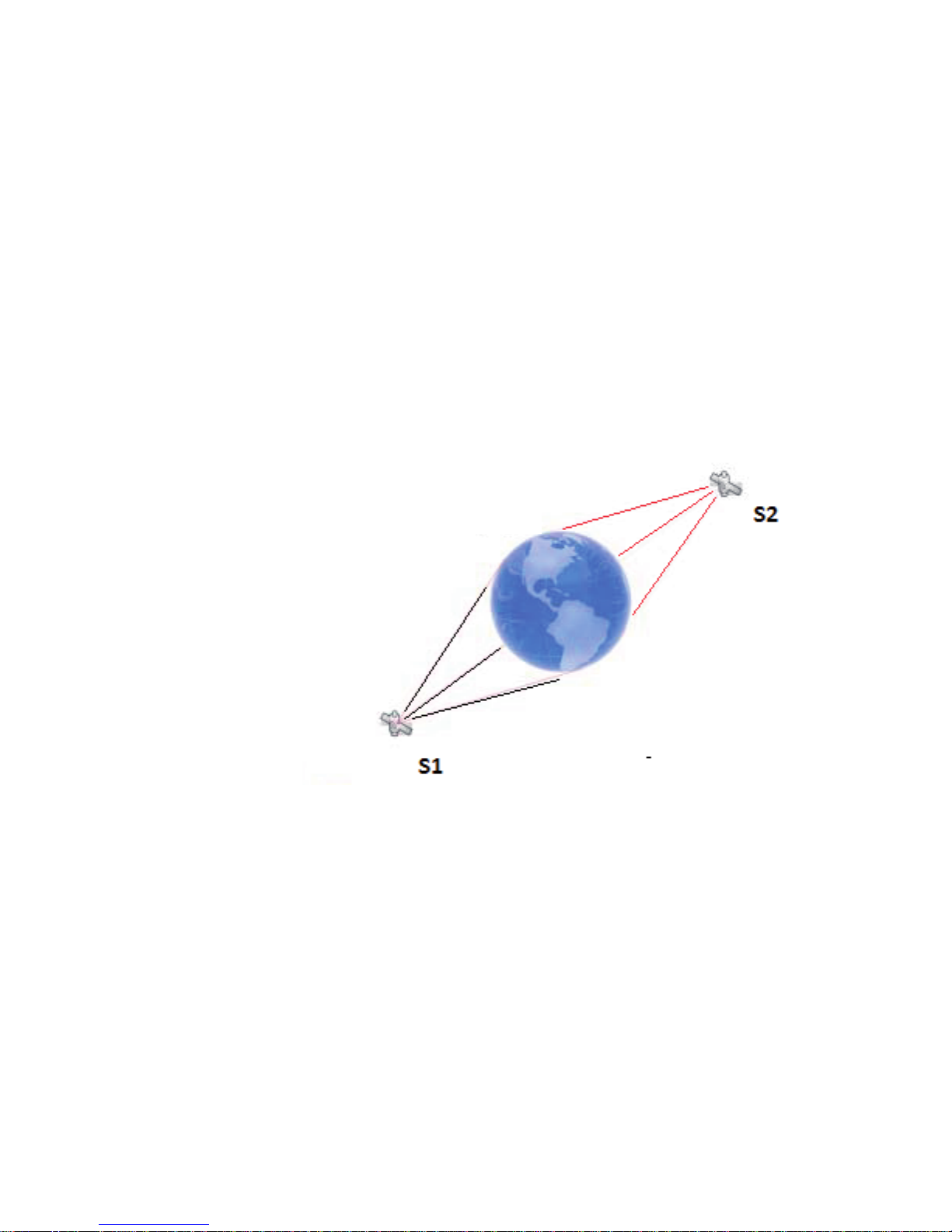
The GLONASS system is based on 24 satellites using
12 different frequencies. This was made possible by
using the same frequency on antipodal satellites. These
are satellites that are in the same orbital plane but are
separated by 180°.
Antipodal Satellites
Both satellites are transmitting
on the same frequency
GPS and GLONASS
Combining the GPS and GLONASS system provides the
following advantages:
• Better signal acquisition times
• Better position and time accuracy
• Reduces the physical blocking of signal in urban cities
where tall buildings are the norms
• Better satellite geometry resulting in better HDOP
 Loading...