

Simrad ITI TRAWL SYSTEM - SERIAL DATA COMMUNICATION REV A,ITI TRAWL SYSTEM Instruction Manual
Simrad ITI Trawl System
Serial data communication and
NMEA 0183 message description
111110 10 00101 0101 010
010101001 00010100011
010101010 00101010100
10101001100001111.................
Instruction manual


Simrad ITI Trawl system
Serial data communication and
NMEA 0183 message description
Instruction manual
857--164777 / Rev.A

Note
Simrad AS makes every effort to ensure that the information contained within this
document is correct. However, our equipment is continuously being improved and
updated, so we cannot assume liability for any errors which may occur.
Warning
The equipment to which this manual applies must only be used for the purpose for which
it was designed. Improper use or maintenance may cause damage to the equipment or
injury to personnel. The user must be familiar with the contents of the appropriate manuals
before attempting to operate or work on the equipment.
Simrad AS disclaims any responsibility for damage or injury caused by improper
installation, use or maintenance of the equipment.
Copyright
E 2003 Simrad AS
ISBN 82-8066-013-5
The information contained within this document remains the sole property of Simrad AS.
No part of this document may be copied or reproduced in any form or by any means, and
the information contained within is not to be communicated to a third party, without the
prior written consent of Simrad AS.
Support
For support on your Simrad equipment, consult your local dealer, visit www.simrad.com,
or contact us directly at support.fish@simrad.com.
Simrad AS
Strandpromenaden 50
Box 111
N-3191 Horten
Telephone: +47 33 03 40 00
Facsimile: +47 33 04 29 87
A L W A Y S A T T H E F O R E F R O N T O F T E C H N O L O G Y
Instruction manual
I
857-164777 / A
Sections
This book is the Instruction manual manual for the ITI system.
1INTRODUCTION
2
ITI TRAWL SYSTEM, BASIC PRINCIPLE
3
ITI GEOMETRY FOR TWIN RIG
4 RESPONSIBILITY
5 SERIAL LINES
6 NMEA 0183 MESSAGES, DEFINITIONS
7NMEA–
ABBREVIATIONS, ITI AUX MENU SELECTIONS
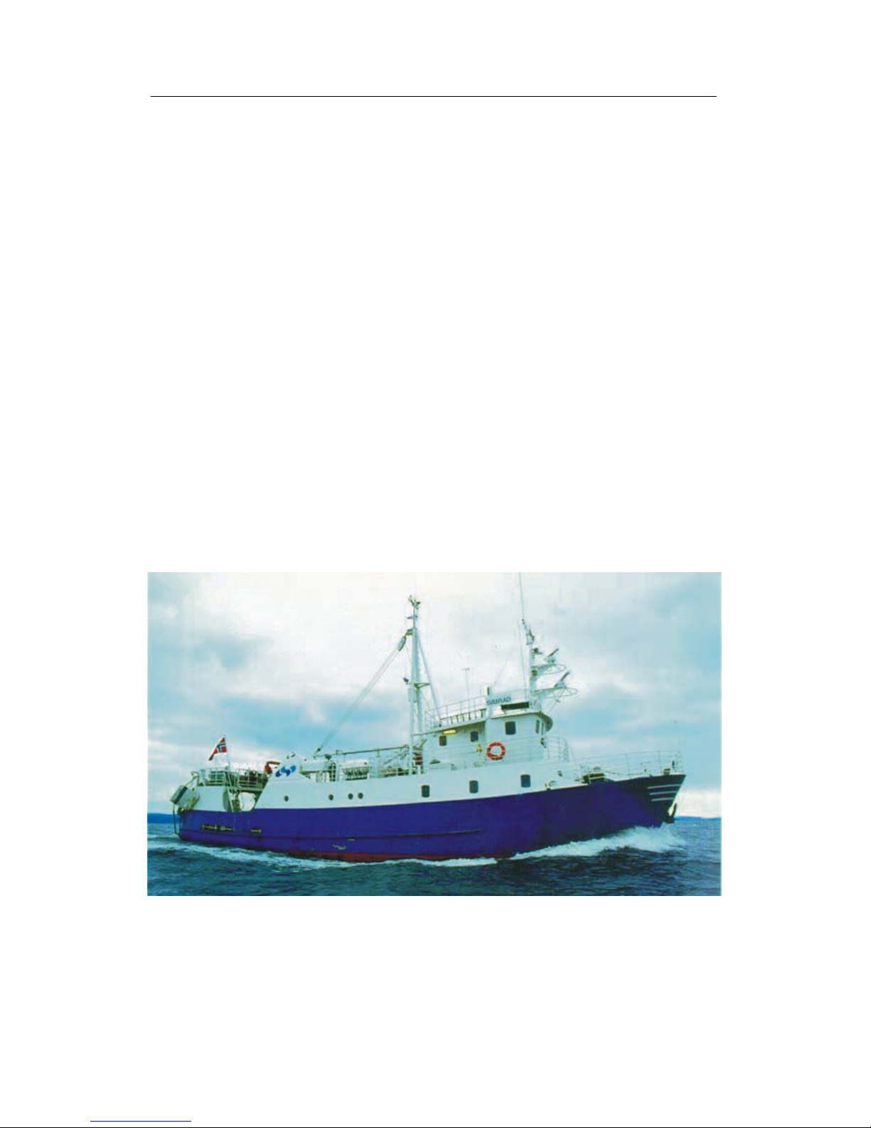
(Cd6911)
M/S simrad Echo, our research and demonstration vessel

Simrad ITI
II
857-164777 / A
Remarks
References
Further information about the ITI system supplied may befound in the following manuals:
• ITI Installation manual
• ITI Trawl Eye Instruction manual

Instruction manual
III
857-164777 / A
Contents
1INTRODUCTION 1..........................................
2 ITI TRAWL SYSTEM, BASIC PRINCIPLE 2................
3ITIGEOMETRYFORTWINRIG 3..........................
4 RESPONSIBILITY 5........................................
5 SERIAL LINES 6............................................
Transmitted messages 6..........................................
Received message 8.............................................
Serial line configuration and pin allocations 9.........................
Serial port pin assignments 10......................................
6 NMEA 0183 MESSAGES, DEFINITIONS 11.................
Message description 11............................................
NMEA output from ITI 12.........................................
NMEA Input to ITI 23.............................................
Telegram from Winch Syncro 2020 25...........................
7 NMEA – ABBREVIATIONS, ITI AUX MENU SELECTIONS 26
Simrad ITI
IV
857-164777 / A
Document logistics
Rev Date Written Checked Approved
A 23.09.03 GM KRA KRA
B
C
D
(The original signatures are recorded in the company’s logistic database.)
Rev Comments
A Original issue.
B
C
D
To assist us in making improvem ents to the product and tothis manual, we would welcome
comments and constructive criticism. Please send all such - in writing or by e-mail - to:
Simrad AS
Documentation Department
P .O.Box 111
N-3191 Horten
Norway
or e-mail:
simrad.documentation@simrad.com

Instruction manual
1
857-164777 / A
1INTRODUCTION
Note This document is inte nded for software engeneers. It is to be used
for writing codes in order to communicate with the ITI system.
With the rapid development of marine electronic devices, it has
become necessary to develop a standardised interface protocol for
exchanging data between devices regardless of the device
manufacturer. The NMEA 0183 standard protocol for interfacing
electronicmarinedeviceshas been implemented inthe ITI system.
The most common way of connecting electronic equipment is to
use serial lines.
A more powerful way of integrating, is the Ethernet standard with
highersignalling capacity.The softwarerequiredto communicate
over the Ethernet is included in theITI system, however astandard
ITI does not include the hardware required.
A dedicated interface/display board containing the Ethernet
hardware must be installed.
→ Please refer to the Simrad ITI Installation Manual, Appendix 1
page 3 – 17 for more details.
The ITI system has four serial lines available for external
equipment connection.
→ Please refer to page 6 for more details.
Simrad ITI
2
857-164777 / A
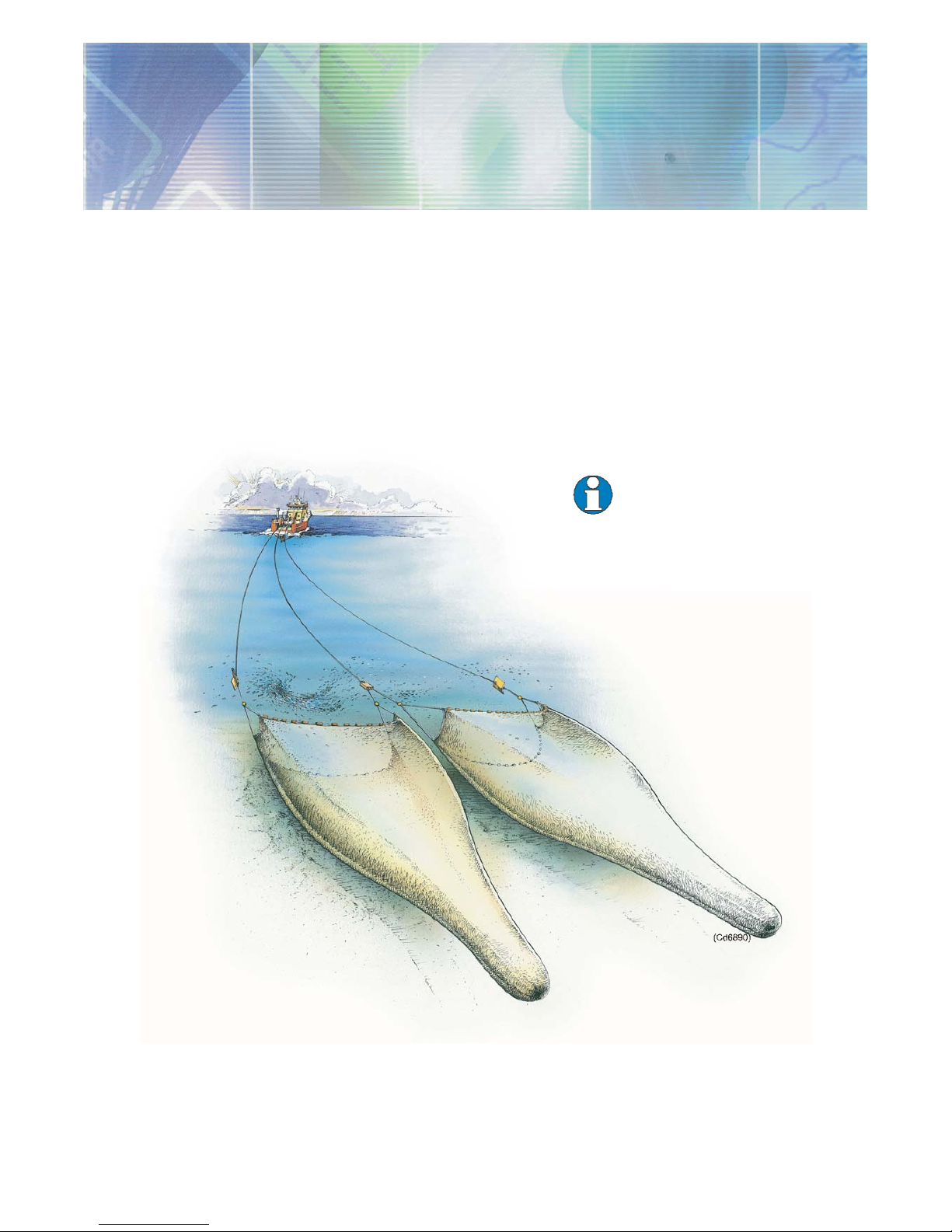
2 ITI TRAWL SYSTEM, BASIC PRINCIPLE
The Simrad ITI wireless trawl positioning and monitoring system
is designedto improvecontrol andefficienc y inpelagic andbottom
trawling. Small robust battery powered sensors mounted on the
trawl, transmit important information to the vessel on request.
• The ITI providesthe skipper with exact position ofthe gear and
what is happening in and around the trawl. It also provides all
crucial information for an effective, profitable and responsible
fishing.
• The ITI is a modular system. From a basic unit of one sensor,
the ITI system can be extended to a complete and advanced
instrument package according to the customers requirements.
Distance and
Speed sensor
Trawl Eye
Depth and
Temperature Sensor
Catch Sensor
Simrad’s philosophyis to reduce integration costsand increase the
benefit of our products to let data from the ITI be available for
integration with external equipment like chart plotters, winch
control systems etc.
Instruction manual
3
857-164777 / A
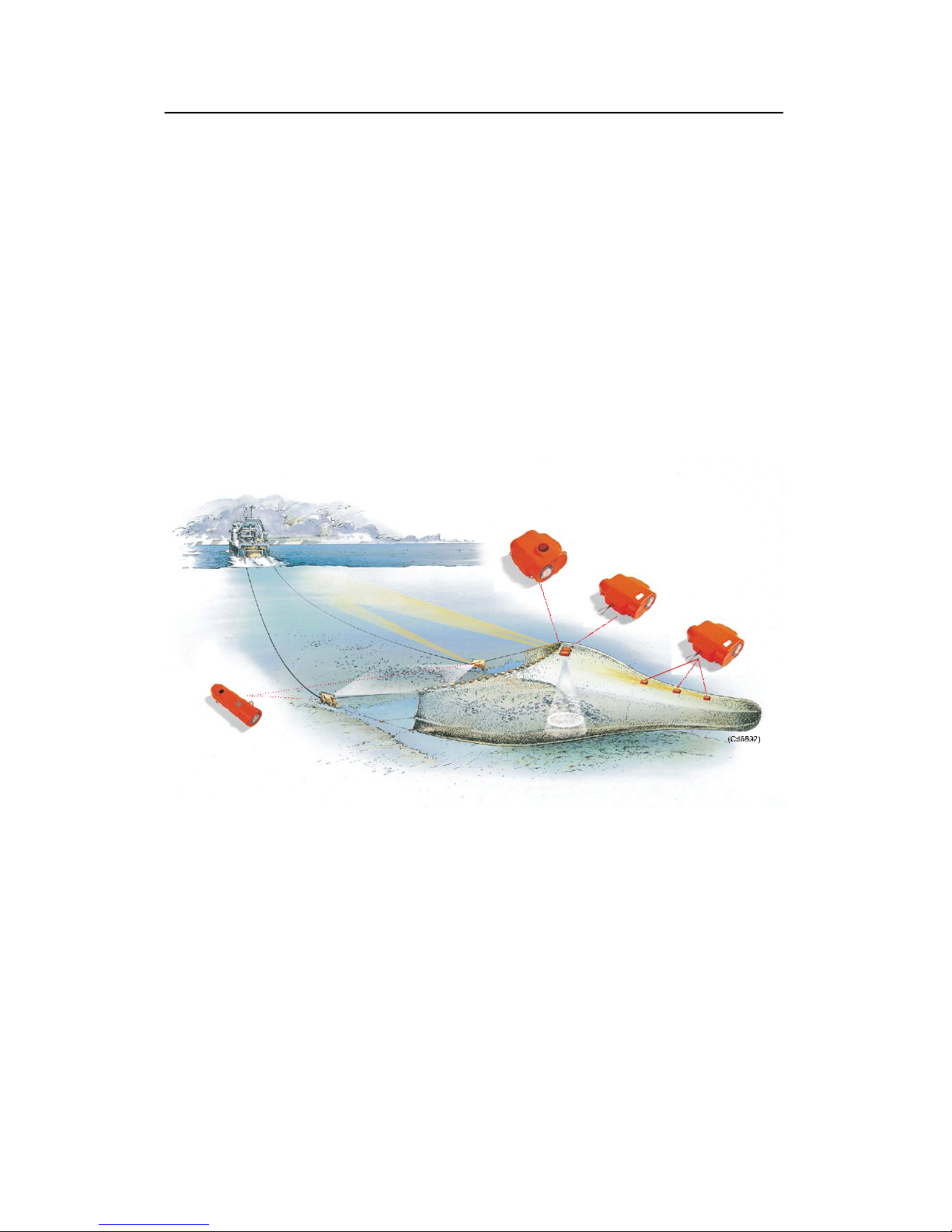
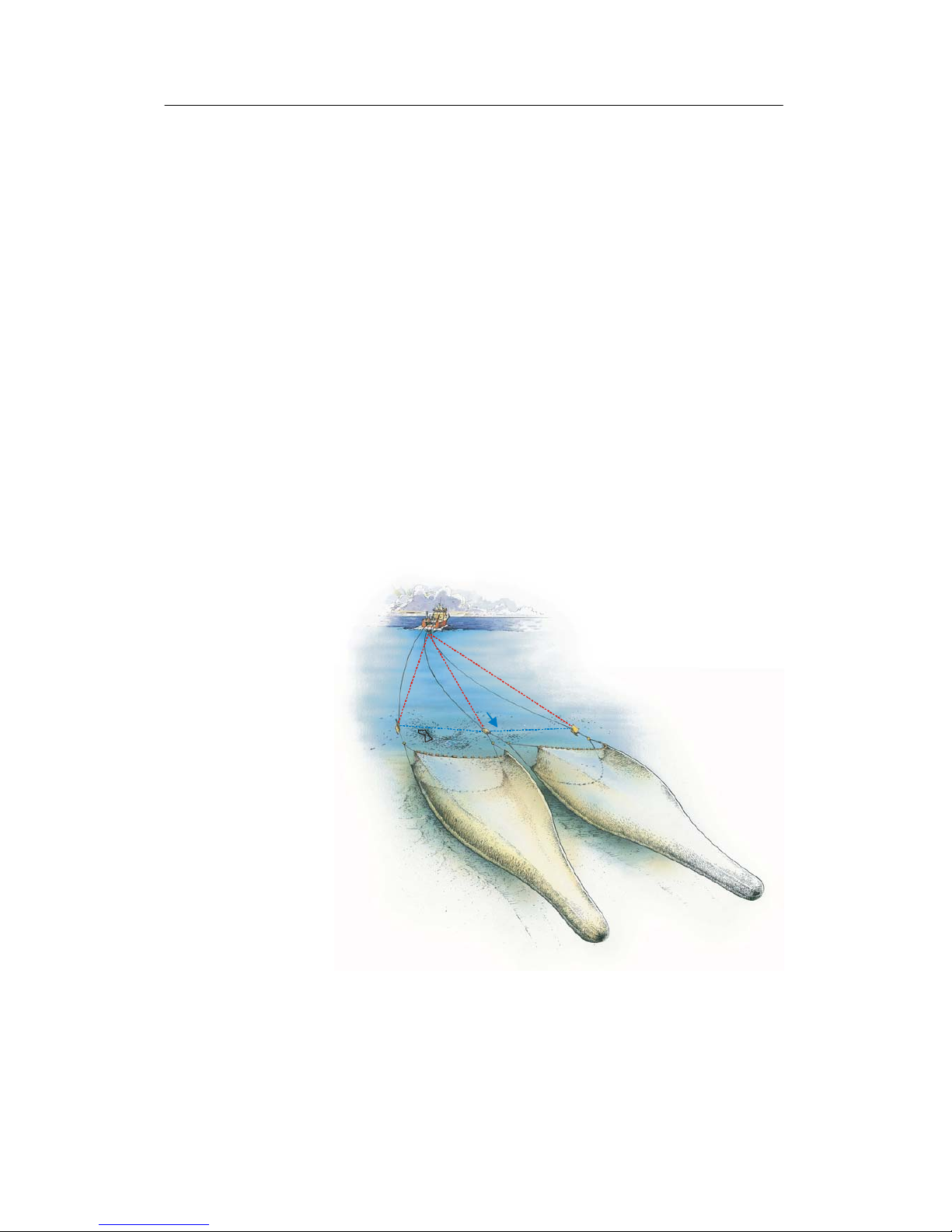
3 ITI GEOMETRY FOR TWIN RIG
Settingup a three wire TwinRig system isa question of findingthe
balance point between a number of f orces. The adjustment of the
centre warp is very critical. This is one of the reason for the
positioning of the clump, and hence the balance of forces between
the doors and the warp and sweeps being so critical to get a square
tow.
• The ITI Geometry System provides the skipper with crucial
information toadjustthe Twin Rig correctlyand henceoptimise
the efficiency of both trawls during the tow.
The ITI Geometry System is based on measurements of the
distance from the vessel to both trawl doors and to the clump. In
addition, the distances between each door and the clump are
measured based on transponders attached to the clump. Based on
these range measurements, the geometry of the Twin Rig is
calculated with high accuracy since all measurements are relative
to each other.
1.3
30
28
310 307 309
(Cd6891)
Theclump positionrelative toa straightline betweenthe doorswill
affect the geometryof the trawl. To get a square tow, the deviation
from the straight line position should be close to zero.
This is a focus point for the ITI Geometry System. In a ddition, the
angle between the true course over ground (VTG) and the straight
line between the doors are calculated and displayed.
 Loading...