

Page 1
Instruction manual
Simrad ITI Trawl System
Serial data communication and
NMEA 0183 message description
111110 10 00101 0101 010
010101001 00010100011
010101010 00101010100
10101001100001111.................
Page 2

Page 3

Simrad ITI Trawl system
Serial data communication and
NMEA 0183 message description
Instruction manual
857--164777 / Rev.A
Page 4

Note
Simrad AS makes every effort to ensure that the information contained within this
document is correct. However, our equipment is continuously being improved and
updated, so we cannot assume liability for any errors which may occur.
Warning
The equipment to which this manual applies must only be used for the purpose for which
it was designed. Improper use or maintenance may cause damage to the equipment or
injury to personnel. The user must be familiar with the contents of the appropriate manuals
before attempting to operate or work on the equipment.
Simrad AS disclaims any responsibility for damage or injury caused by improper
installation, use or maintenance of the equipment.
Copyright
E 2003 Simrad AS
ISBN 82-8066-013-5
The information contained within this document remains the sole property of Simrad AS.
No part of this document may be copied or reproduced in any form or by any means, and
the information contained within is not to be communicated to a third party, without the
prior written consent of Simrad AS.
Support
For support on your Simrad equipment, consult your local dealer, visit www.simrad.com,
or contact us directly at support.fish@simrad.com.
Simrad AS
Strandpromenaden 50
Box 111
N-3191 Horten
Telephone: +47 33 03 40 00
Facsimile: +47 33 04 29 87
A L W A Y S A T T H E F O R E F R O N T O F T E C H N O L O G Y
Page 5
Sections
This book is the Instruction manual manual for the ITI system.
1INTRODUCTION
Instruction manual
2
3
ITI TRAWL SYSTEM, BASIC PRINCIPLE
ITI GEOMETRY FOR TWIN RIG
4 RESPONSIBILITY
5 SERIAL LINES
6 NMEA 0183 MESSAGES, DEFINITIONS
7NMEA–
ABBREVIATIONS, ITI AUX MENU SELECTIONS
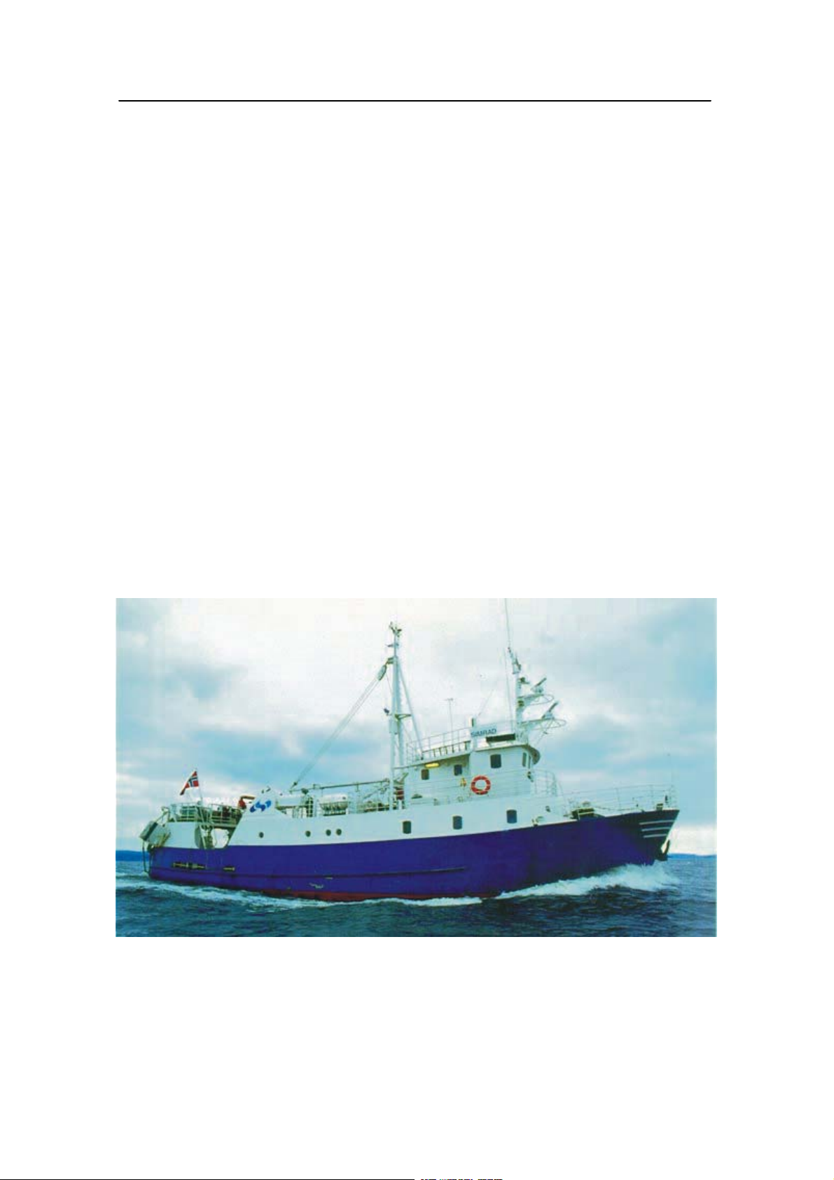
(Cd6911)
M/S simrad Echo, our research and demonstration vessel
857-164777 / A
I
Page 6

Simrad ITI
Remarks
References
Further information about the ITI system supplied may befound in the following manual s:
• ITI Installation manual
• ITI Trawl Eye Instruction manual
II
857-164777 / A
Page 7

Instruction manual
Contents
1INTRODUCTION 1..........................................
2 ITI TRAWL SYSTEM, BASIC PRINCIPLE 2................
3ITIGEOMETRYFORTWINRIG 3..........................
4 RESPONSIBILITY 5........................................
5 SERIAL LINES 6............................................
Transmitted messages 6..........................................
Received message 8.............................................
Serial line configuration and pin allocations 9.........................
Serial port pin assignments 10......................................
6 NMEA 0183 MESSAGES, DEFINITIONS 11.................
Message description 11............................................
NMEA output from ITI 12.........................................
NMEA Input to ITI 23.............................................
Telegram from Winch Syncro 2020 25...........................
7 NMEA – ABBREVIATIONS, ITI AUX MENU SELECTIONS 26
857-164777 / A
III
Page 8

Simrad ITI
Document logistics
Rev Date Written Checked A pproved
A 23.09.03 GM KRA KRA
B
C
D
(The original signatures are recorded in the company’s logistic database.)
Rev Comments
A Original issue.
B
C
D
To assist us i n making improvements to the product and to this manual, we would welcome
comments and constructive criticism. Please send all such - in writing or by e-mail - to:
Simrad AS
Documentation Department
P.O.Box 111
N-3191 Horten
Norway
IV
or e-mail:
simrad.documentation@simrad.com
857-164777 / A
Page 9

Instruction manual
1INTRODUCTION
Note This document is intended for software engeneers. It is to be used
for writing codes in order to communicate with the ITI system.
With the rapid development of marine electronic devices, it has
become necessary to develop a standardised interface protocol for
exchanging data between devices regardless of the device
manufacturer. The NMEA 0183 standard protocol for interfacing
electronicmarinedeviceshas been implementedin the ITIsystem.
The most common way of connecting electronic equipment is to
use serial lines.
A more powerful way of integrating, is the Ethernet standard with
highersignalling capacity. The softwarerequired to communicate
over the Ethernet is includedi n the ITI system, however a standard
ITI does not include the hardware required.
A dedicated interface/display board containing the Ethernet
hardwa re must be installed.
→ Please refer to the Simrad ITI Installation Manual, Appendix 1
page 3 – 17 for more details.
The ITI system has four serial lines available for external
equipment connection.
→ Please refer to page 6 for more details.
857-164777 / A
1
Page 10
Simrad ITI
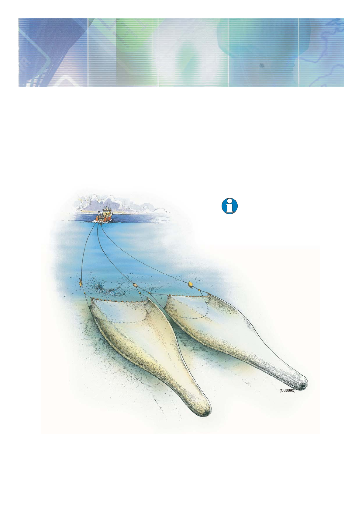
2 ITI TRAWL SYSTEM, BASIC PRINCIPLE
The Simrad ITI wireless trawl positioning and monitoring system
is designedto improvecontrol andefficiency inpelagic andbottom
trawling. Small robust battery powered sensors mounted on the
trawl, transmit important information to the vessel on request.
• The ITI provides the skipper with exact position of the gear and
what is happening in and around the trawl. It also provides all
crucial information for an effective, profitable and responsible
fishing.
• The ITI is a modular system. From a basic unit of one sensor,
the ITI system can be extended to a complete and advanced
instrument package according to the customers requirements.
Trawl Eye
Distance and
Speed sensor
Depth and
Temperature Sensor
Catch Sensor
Simrad’s philosophy is to reduce integration costs and increase the
benefit of our products to let data from the ITI be available for
integration with external equipment like chart plotters, winch
control systems etc.
2
857-164777 / A
Page 11
3 ITI GEOMETRY FOR TWIN RIG
Settingup a three wire Twin Rig system is a questionof findingthe
balance point between a number of forces. The adjustment of the
centre warp is very critical. This is one of the reason for the
positioning of the clum p, and hence the balance of forces between
the doors and the warp and sweeps being so critical to get a square
tow.
• The ITI Geometry System provides the skipper with crucial
informationto adjustthe Twin Rig correctlyand henceoptimise
the efficiency of both trawls during the tow.
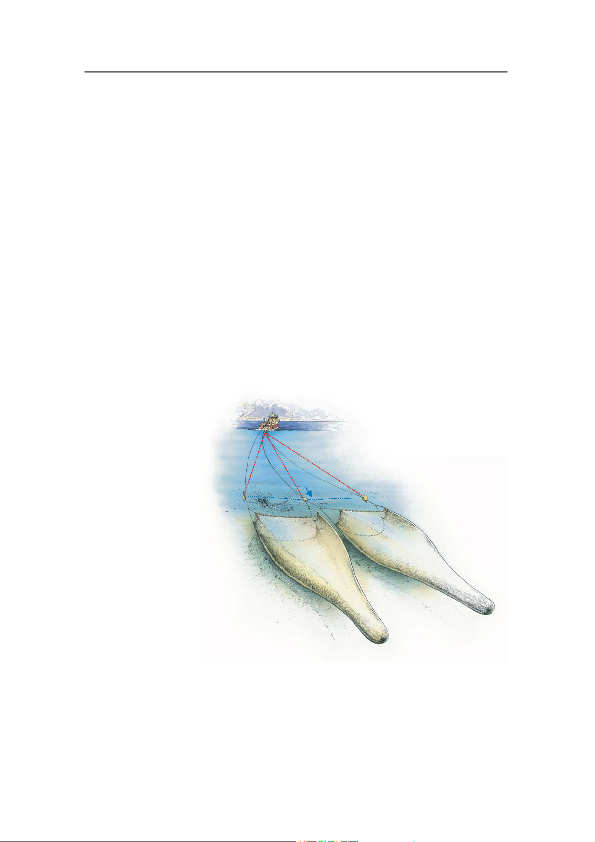
The ITI Geometry System is based on measurements of the
distance from the vessel to both trawl doors and to the clump. In
addition, the distances between each door and the clump are
measured based on transponders attached to the clump. Based on
these range measurements, the geometry of the Twin Rig is
calculated with high accuracy since all measurementsare relative
to each other.
Instruction manual
310 307 309
28
1.3
30
(Cd6891)
Theclump positionrelative to a straightline betweenthedoorswil l
affect the geometry of the trawl.Toget a square tow, the deviation
from the straight line position should be close to zero.
This is a focus point for the ITI Geometry System. In addition, the
angle between the true course over ground (VTG) and the straight
line between the doors are calculated and displayed.
857-164777 / A
3
Page 12

Simrad ITI
The figure above shows tha t the trawl is 3_ off port side. The doors
and the clump are not lined up correctly with door/clump distances
of 28 and 30 meter. The distances to the trawl doors are 310 and
309 meter and distance to the clump is 307 meters. In order to
obtain maximum door spread and a square tow, the middle wire
should be paid out 1.3 meter.
Note The trawl geometry is comparedto the course over ground showing
_
with 90_being optimum.
94
Both trawl heights are 3,2 meter and the Trawl Eye echogram
shows that the port trawl has good bottom contact but for the
moment , with a few fishes in the opening. One Catch Sensor is
mounted on the port cod end. The trawl is 6:20 min. behind the
vessel, the clump has a light bottom contact ascending 0,4 m/min.
Depth below the vessel is 120 meter and the temperature at the
trawl is 5,8_ C. In addition, heading, speed and Lat./Long. are
displayed.
The ITI Geometry for Twin Rig will be implemented in the ITI
topside software, ve rsion 5.20 or above.
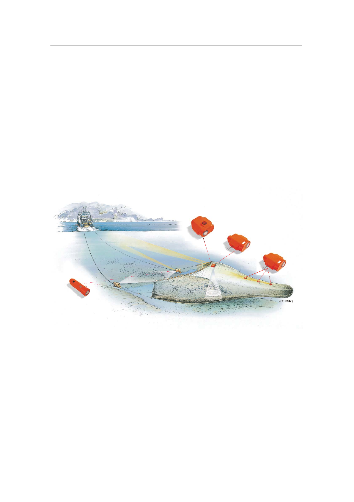
(Cd6 893)
The picture shows a Twin Rig trawl with the Trawl Eye echogram
showing the trawl opening.
4
857-164777 / A
Page 13

4 RESPONSIBILITY
Simrad’s philosophy is to let data from our ITI Trawl System be
available for integration with external equipment like chart
plotters, winch control systems etc. Weare convinced that thiswill
increase the benefit of the product and lead to reduced integration
costs.
The quality of the transmission data depends on:
• sea condition
• dept h
• temperature layers
• multipath
• most important - the noise level from the propeller becauseyou
are receiving the signals from astern.
Compared to serial line data communication channel, the
hydroacoustic transmission channel is far more unstable with data
errors and intermittent interruption of the data transmission as a
result.
Instruction manual
Theappropriatefilteringanddisplayalgorithm usedby Simradfor
displaying the data on a CRT, might not be the optimum for
applic ations, which are using the data as part of input parameters
for controlling or regulating winches etc.
Simrad will therefore emphasise, to any one who are using the ITI
data, to design an application specific filtering and adding
”artificial intelligence” to the use of- and interpreting the data
received.
We will not involve ourselves in applications using our data but
any user will have access to the data from the ITI as described in
this manual. If special agreements are made,Simradcan supply log
files recorded during actual towings for test and simulation
purposes.Beyond that, Simrad have limitedcapacity to assist users
of the ITI data in their application.
The use of the ITI data is t he users responsibility and Simrad
disclai m responsibility for any consequences of using data from
the ITI.
857-164777 / A
5
Page 14

Simrad ITI
5 SERIAL LINES
The ITI system has four (female) serial ports, A, B C and D. All
message transferred via these serial lines are basedon the NMEA
0183 format protocol.
ETHERNE T REMOTE CONTROL MONITO R
B
(Cd4346)
C
D
TD-L TD-R
A
230 V mains supply
CE NTRO NIX
Gyro-compass,
l og, etc.
Port A, C and D have the following dedicated functions:
• Port A for connection to an echo sounder
• Port C to a sonar
• Port D to a navigator.
Port B is dedicated for:
• Auxiliaryequipment like Winch control system, Track plotter,
data l ogger etc.
If port C is not used by the sonar the port might be used for optional
output of the Trawl position (GLL) to an auxiliary plotter. PortA,
B and C have two-way communication while port Donl y has input
data. All four serial lines can receive telegrams without being
activated from the menu.
Ports A, B and C must be activated from the menu before any
messages being transmitted.
Transmitted messages
A NMEA telegram will be transmitted when its data has been
updated. Each individual parameter available on the serial line B
(AUX) can be turned ON or OFF from the menu.
Individual param eters can not be set ON or OFF on serial lines A
and C. These two serial lines have been allocated for interfacing
to Echo sounder and Sonar respectively, and al l parameters on any
of these two lines are either activated or not activated.
No parameters are transmitted out on serial port D.
6
857-164777 / A
Page 15

Instruction manual
Serial line D
Navigator
Serial line A
Echosounder
$IIDBS
@IIHFB
@IIHB2
$IIZDL
Serial line B
Aux
@IITDS
@IITS2
@IIHFB
$IIMTW
@IITFI
@IITPT
@IITPC
@IITTS
$IIGLL
$IIVTG
$SDDBS
$IIDBS
@IIHB2
@IIDAD
$PSIMT
$PSIMTH
$PSIMMW
$PSIMS1
$PSIMS2
$IIZDA
$PSIMH1
$PSIMH2
$PSIMG1
$PSIMG2
$PSIMCA
$PSIMDE
$PSIMTM
Serial line C
Sonar
@IITDS
@IITS2
@IIHFB
$IIMTW
@IITFI
@IITPT
@IITPR
$IIDBS
@IIDAD
@IIHB2
Ethernet
Aux
@IITDS
@IITS2
@IIHFB
$IIMTW
@IITFI
@IITPT
$IIGLL
@IIDAD
@IIHB2
@IITPC
857-164777 / A
Table 1 Transmitted messages
Table 1 shows the different parameters that can be transmitted by
ITI when activated in the menu.In addition,all messagesreceived
on serial line B can be transferred out on Ethernet.
This transfer facility is activated from the command:
NMEA TRANSFER.
Optiona lly $IIGLL (trawl posit ion) is available on Port C. This
require the parameter TEST2 to be set to 8 (Menu /
SYSTEMSETUP / TRAWL EYE), and is then independent on
whether SONAR OUTPUT has been activated.
7
Page 16

Simrad ITI
Received message
All messages listed in table 2 can be received at any time without
acti vating them from the menu. As described above, by settingthe
NMEA TRANSFER command to ON, all messages received on
Ethernet will be transmitted out on serial port B, and vice versa.“-
-” means any character will be accepted.
Serial line D
Navigator
$----GLL
$----VTG
$----ZDA
Serial line A
Echosounder
$SDDBS
$----DBT
Serial line B
Aux
$----GLL
$----VTG
$SDDBS
$----DBT
$----HDT
$----HDM
$----HDG
$----ZDA
@SSTPP
@TAWWL
@TAWWT
$WMSYN
Serial line C
Sonar
$----HDT
$----HDM
$----HDG
@SSTPP
Table 2 Received messages
Ethernet
Aux
$----GLL
$----VTG
$SDDBS
$----DBT
$----HDT
$----HDM
$----HDG
$----ZDA
@SSTPP
@TAWWL
@TAWWT
$WMSYN
8
857-164777 / A
Page 17

Instruction manual
Serial line configuration and pin allocations
→ Refer to drawing no. 824-108590, ITI Installation manual.
The four seri al port (fe male) connectors are found on the
transceiver unit plug panel, located in the bottom of the cabinet.
The serial lines can be configured electrically as follows:
• Port A can be configured as RS-232 or RS-422.
• Ports B and C are standard RS-232 serial lines only.
• Port D can be configured as RS-232, RS-422 or current loop.
Table 3 gives an overview of the different ways of configuring the
serial lines electrically, and the dedicated use of each line.
Port
Possible
ITI port allocation Format
configurations
A RS-232 Echo sounder NMEA 0183
B RS-422 - Winch control
NMEA 0183
- Track plotte r
- Data logge r
C RS-232 Sonar NMEA 0183
D - RS-232
-- RS-422
-- 20 mA Current loop
Navigator NMEA 0183
Table 3 Possible serial port configurations and allocations
→ Refer to the ITI installation manual for further information
regarding configuration port A and D.
857-164777 / A
9
Page 18

Simrad ITI
Serial port pin assignments
The ITI system is designed to communicate over serial interfaces
where control signals are not required. The connectors in the
cabinetare femaleand requirea maleconnectorfor the serialcable.
Table 4 shows the pin assignments for port B (and C) available on
the ITI transceiver cabinet.
Pin
Name Description
1
2
3
RX DA2
TX DA2
Receive data RS-232 NMEA RX A
Transmit data RS-232 NMEA TX A
4
5
GND
Signal ground RS-232 NMEA RX/TX B
6
7
8
RT SA2
CT SA2
Request to send RS-232
Clear to send RS-232
9
Table 4 Pin assignments - ports B and C
Note The RS-232 inputs of port A-D do not meet the optoisolation
requirements of the NMEA standard and precautions should be
taken thereafter.
→ Refer to the ITI Installation manual for pin assignments of port A
and D.
10
857-164777 / A
Page 19

Instruction manual
6 NMEA 0183 MESSAGES, DEFINITIONS
Messages transmitted and received on serial lines or Ethernet are
all base d on the NMEA 0183 data format protocol.
The main characteristics are as follows:
• RS-422A asynchronous serial line
• 4800 baud
• 8 data bits
• No parity
• One or more stop bits
• All data coded in ASCII code
• Optional ”X-OR” checksum
All messages start with either; “$” or “@”.
Telegram s starting with “$” do fully comply with the NMEA 0183
data form at protocol.
• All other telegrams are in accordance with an old proprietary
“Simrad standard.” They start with @, but otherwise they
follow the main characteristics listed below.
• The next two letters (Talker identifier) indicate which system
is transmitting the messages. Simrad ITI System uses II as a
talker identifier.
• The next three lettersindicate the type of message. The telegram
may consist of many data fields separated by commas. A field
may be empty, and then only the separating commas are
transmitted, also called nullfields.
• Each message ends with <cr>(Carriage Return) and <lf> (Line
Feed). For all message starting with ”$” the checksum *hh is
included in compliance with version 2.20 of the NMEA 0183
standard, - no checksum on ”@” sentences.
Throughout this document, all telegrams with II as the Talker
identifier, and telegrams with the proprietary code PSIM,are
originated by ITI and transmitted to other equipment. All
telegrams with other Talker identifiers are received by ITI from
external equipment.
Message description
Below you will find the message description for IT I topside
software version 5.30 or above. The different types of telegrams
are not listed in consecutive order.
Note The *hh check sum, <cr> carriage return and <lf> line feed are
not described for each sentence.
857-164777 / A
11
Page 20

Simrad ITI
NMEA output from ITI
$IIVTG,,,xxx,M,yy.y,N,,*hh<cr><lf>Ve ssel course and speed
→ requires input from a nav. Receiver.
VTG represents the Vessel Track over t he Ground.
xxx,M is the track be aring, in degre es magnetic.
yy.y,N is the speed i n knots relative to ground.
$IIZDA,hhmmss.ss,dd,MM,yyyy,xx,xx*hh<cr><lf> Time & Date of ITI
→ equals UTC±5 seconds if GPS connected.
hh is the hours
mm is the minutes
ss.ss is the seconds and par ts of seconds
dd is the day’s date
MM is the month
yyyy is the year
xx,xx is the local time zone (hh,mm)positive offset east ofGreenwich.
@IITPT,xxxx,M,y,P,zzzz.z,M<cr><lf> Trawl Position True vessel
TPT represents the True Trawl Position relative to the vessel.
xxxx,M is the horizonta l range in metres to the target (0 - 4000 m).
- requires an active depth sensor on the trawl or manual set
depth, if not the slant range will be presented.
yyy,P Is the true bearing to the target (i.e. relative to north).
(Resolution 1°.)
- requires gyro input for reliable data.
zzzz.z,M is the depth in metres of trawl below the surface (0 - 2000 m).
- requires an active depth sensor on the trawl or manual set
depth, if not the depth field will be empty.
12
857-164777 / A
Page 21

Instruction manual
@IITPC,x,M,y,M,z,M<c r><lf>Trawl Position in Cartesian co-ordinates
TPC represents the Trawl Position in Cartesian co-ordinates.
x,M isthe horizontal distancein metresfrom vesselcentre line.Value
is positive if trawl is on starboard side, negative if on port side.
- requires an active depth sensor on the trawl or manual set
depth, if not the slant range will be presented.
y,M is the horizontal distance in metres from the transducer to the
trawl along the vessel’s centre line. The value will normally be
positive as the trawl is usually behind the vessel.
- requires an active depth sensor on the trawl or manual set
depth, if not the slant range will be presented.
z,M is the depth of the trawl in metres below the surface. the value is
normally positive.
- requires an active depth sensor on the trawl or manual set
depth, if not the depth field will be empty.
$IIGLL,ddmm.hhh,N,dddmm.hhh,W ,hhmmss.ss,A*hh<cr><lf>
Trawl Position in Latitude and Longitude
GLL represents the trawls Geographical Latitude and Longitude.
- requires GLL input from a nav. Receiver.
ddmm.hhh,N is t he Latitude, Deg.Min.Hundredths, N=North, S=South.
dddmm.hhh,W is the longitude, Deg.Min.Hundredths, W=West, E=East.
hhmmss.ss UTC of position (time stamp, fraction of seconds void).
- requires ZDA input from GPS for accurate timestamp.
A valid
- never invalid, terminates output after one minute without
GLL input from a nav. Receiver.
$IIDBS,,,xxxx.x,M,,*hh<cr><lf>Depth of trawl Below Surface
DBS represents Depth of the trawl Below the Surface.
857-164777 / A
xxxx.x,M i s the depth in metres (0 - 2000). The fields for depth in feet and
fathoms are empty.
- requires an a ctive depth sensor on the trawl.
13
Page 22

Simrad ITI
$IIMTW,-xx.x,C*hh<cr><lf> Water t emperature at the trawl
MTW represents the Meteorological Temperature in the Water.
xx.x is the water temperature (° C) measured at the trawl.
(Sign prefix only if minus.) Range from -5° Cto+30° C.
C means the value is in ° Celsius.
- requires an a ctive temperature sensor on the trawl.
@IIHFB,x.x,M,y.y,M <cr><lf>
Trawl Headrope to Footrope and Bottom (Trawl Eye/Height sensor 1)
HFB represents the distances from the Headrope to the Footrope and
Bottom.
x.x,M i s the distance in metres from headrope to footrope (0 - 100 m).
y.y,M is the distance in metres from headrope to bottom (0 - 100 m).
@IIHB2,x.x,M,y.y,M<cr><lf>
Trawl Headrope to Footrope and Bottom (Height sensor 2)
HB2 representsthe distances from the Headrope to the Footrope and
Bottom.
x.x,M isthe distance in metres from headrope to footrope (0 -- 100m).
y.y,M is the distance in metres from headrope to bottom (0 -- 100 m).
@IITDS,x.x,M<cr><lf> Trawl Door Spread 1
TDS represents the Trawl Door Spread 1 distance.
x.x,M i s the spread distance in metres (0 - 300 m)
- if invalid, nullfields will be transmitted
- filtered values if sensorfilter is on.
@IITS2,x.x,M<cr><lf> Trawl Door Spread 2
TS2 represents the Trawl Door Spread 2 distance.
x.x,M i s the spread distance in metres (0 -300 m)
- if invalid, nullfields will be transmitted
- filtered values if sensorfilter is on.
14
857-164777 / A
Page 23

Instruction manual
$PSIMTH,x.x,M,y.y,M*hh<cr><lf>
Trawl Headrope to Footrope and Bottom (Trawl Eye/Height sensor 1)
TH represents the distances from the Headrope to the Footrope and
Bottom.
x.x,M i s the distance in metres from headrope to footrope (0 - 100 m).
y.y,M is the distance in metres from headrope to bottom (0 - 100 m).
$PSIMTE,xx%y,xx%y,xx%y,xx%y,xx%y,xx%y,xx%y,xx%y,xx%y,xx%y,a,x.x,M,
Gx,gx,Vx.x *hh<cr><lf> Trawl Eye, Echo telegram, fish detection
TE carries the echo readings from fish detection and the sensor set
up parame ters (type of trawl, range gain etc).
x.x% per cent of samples above threshold for the 10 echo cells.
y average level (1-7) of the xx %. Data skipped if cell is empty or
not avai lable.
a B/P Bottom/Pelagic 10 cells. b/p: bottom/pelagic 5 cells.
x.x,M total range, 2,5 – 50 m of fish detection range.
Gx Gain setting, coarse.
gx g1 – g7 gain setting fine.
Vx.x Version of Trawl Eye Sensor software.
857-164777 / A
15
Page 24

Simrad ITI
$PSIMSn,xxxx,M,xxxx,M,yyy.y,T,xxx.x,M,hhmmss*hh<cr><lf>
nn=1Spread1 (port trawl door when Twin Rig)
n=2 Spread2 (starboard trawl door when Twin Rig)
xxx,M slant range in m etres to sensor
- filtered values
- decimals not used.
xxx,M horizontal range in metres to sensor
- unfiltered values
- nullfields if depth-sensor not activated (will calculate
horizontal range with manual set de pth)
- decimals not used.
yyy.y,T true bearing (deg.rel.north) to sensor
- requires gyro input for reliable data.
xxx.x,M spread measurement in metres (door to door or door to middle
weight)
- if invalid values nullfields will be transmitted
- filtered values if sensorfilter is on.
hhmmss time of transmission (time of Spread interrogation)
- requires ZDA input from GPS for accurate timestam.
$PSIMHn,xxxx,M,xxxx,M,yyy.y,T,zz.z,M,zz.z,M,hhmmss*hh<CR> <LF>
n -n=1height 1 sensor or trawl eye
-n=2height 2 sensor
xxxx,M Slant range in meters to sensor
- filtered values
- decimals not used.
xxxx,M horizontal range in m etres to sensor
- unfiltered values
- nullfields if depth-sensor not activated (will calculate
horizonta l range with manual set depth
- decimals not used.
yyy.y,T true bearing (deg.re l.north) to sensor
16
- requires gyro input for reliable data.
zz.z,M height in metres from headrope to footrope, 0 - 50 m.
zz.z,M height in metres from headrope to bottom, 0 - 100 m
- if invalid values nullfields will be transmitted.
857-164777 / A
Page 25

$PSIMGn,xxxx,M,xxxx,M,yyy.y,T,yz.z,D,hhmmss*hh<CR><LF>
n n=1 grid 1 sensor
n=2 grid 2 sensor
xxxx,M slant range in metres to sensor
- filtered values
- decimals not used.
xxxx,M horizontal range in m etres to sensor
- unfiltered values
- nullfields if depth-sensor not activated (will calculate
horizonta l range with manual set depth
- decimals not used.
yyy.y,T true bearing (deg.re l.north) to sensor
- requires gyro input for reliable data.
Instruction manual
zz.z,D angle of grid, 0-90 degrees
- if invalid values nullfields will be transmitted.
$PSIMCA,xxxx,M,xxxx,M,yyy.y,T,x,y,z ,hhmmss*hh<CR><LF>
CA catch sensor (bearing and range only to activated sensor with
lowest number).
xxxx,M slant range in m etres to sensor
- filtered values
- decimals not used.
xxxx,M horizontal range in metres to sensor
- unfiltered values
- nullfields if depth-sensor not activated (will calculate
horizonta l range with manual set depth
- decimals not used.
yyy.y,T true bearing (deg.rel.north) to sensor
- requires gyro input for reliable data.
x catch1 sensor: 0=off, 1=on, 2=not a ctivated/no answer.
857-164777 / A
y catch2 sensor: 0=off, 1=on, 2=not a ctivated/no answer.
z catch3 sensor: 0=off, 1=on, 2=not activated/no answer.
17
Page 26

Simrad ITI
$PSIMDE,xxxx,M,xxxx,M,yyy.y,T,zzzz.z,M,a,hhmmss*hh<CR> <LF>
DE depth sensor
x.x,M slant range in m etres to sensor
- filtered values
- decimals not used.
x.x,M horizontal range in metres to sensor
- unfiltered values
- nullfields if depth-sensor not activated (will calculate
horizonta l range with manual set depth
- decimals not used.
y.y,T true bearing (deg.rel.north) to sensor
- requires gyro input for reliable data.
zzzz.z,M water depth in metres, 0-2000 metres
- if invalid values nullfields will be transmitted.
a Indicate the menu selected position of the sensor
a=p port , a=c centre, a=s starboard.
$PSIMTM,xxxx,M,xxxx,M,yyy.y,T,zz.z,C,a,hhmmss*hh<CR><LF>
TM temperature sensor
xxxx,M slant range in m etres to sensor
- filtered values
- decimals not used.
xxxx,M horizontal range in metres to sensor
- unfiltered values
- nullfields if depthsensor not activated(will calculate
horizonta l range with manual set depth
- decimals not used.
yyy.y,T true bearing (deg.rel.north) to sensor
- requires gyro input for reliable data.
zz.z,C water temperature in -5 to 30 degrees Celsius
- if invalid values nullfields will be transmitted.
18
a Indicate the menu selected position of the sensor
a=p port, a=c centre, a=s starboard.
Ac ombi sensor (depth/temperature) will generate boththe DE and
TM sentences. The temperature, depth or combi sensor must be
used to show the range t o the remote spread sensor if the geometry
of the trawl system shall be calculated.
857-164777 / A
Page 27

Instruction manual
$PSIMMW,xxxx.x,M,xxxx.x,M,yyy.y,T,z.z,M,y.y,D,c,hhmmss*hh<cr><lf>
xxxx.x,M slant range in m etres to middle weight (clump)
- filtered values.
xxxx.x,M horizontal range in metres to middle weight
- unfiltered values
- nullfields if depth-sensor not activated (will calculate
horizonta l range with manual set depth).
yyy.y,T true bearing (deg.rel.north) to middle weight
- requires gyro input for reliable data.
z.z,M signed deviation in metres (if deviation positive, then middle
weight further out than door-door line)
- an offset to the deviation may be set in the trawlsetup in order
toget the deviationnearzero whenthetrawlgeometryis ideal.
A positive offset will shorten the mid weight wire
- a mid weight filter, filtering the signed deviation, is found in
the trawl setup.
About the mid weight filter:
- the mw filter calculates from unfiltered horizontal ranges for
mw filter setting of 1 to 5 and if active depth sensor on trawl
- the mw filter calculates from filtered horizontal ranges for
mw filter setting of 6 to 10 and active depth sensor on trawl
- the mw filter calculates from filtered slant ranges if no active
depth sensor on trawl.
y.y,D “starboard angle” between true GPS course (or heading if no
GPS) and the “Door-Door Line” of the trawl (0° < y.y < 180°).
c status of data, primarily middle weight deviation status
A: OK
B: OK but ambiguous
(± on deviation, presented range complies with positive
deviation, i.e. the larger range possibility)
C: Uncertain (angle based calculations)
D: Uncertain and ambiguous
E: Invalid data, require d sensors not active
V: Invalid data, throw away
857-164777 / A
W: Invalid and ambiguous.
hhmmss time of transmission
(time of Middle weight deviation calculations)
- requires ZDA input from GPS for accurate timestamP.
19
Page 28

Simrad ITI
Note $PSIMMW will be sent when clumppositionundated, only.Update
of the new angle parameter due only to change of course, is not
supported!
@IITFI,x,y,z<cr><lf> Trawl Filling
TFI represents Trawl Filling.
x,y,z are the catch 1, 2 and 3 messages
(off = 0, on = 1, no answer = 2).
@IITTS,x,M,y,P,z,M<cr><lf> Trawl To Shoal distance
TTS represents the Trawl To Shoal distance.
x,M is the horizontal distance i n metres from the trawl to the shoal in
a direction normal to the vessel’s centre line. The value will be
positive if the shoal is on the starboard side of the trawl,
otherwise negative.
y,M is the horizontal distance in metres from the trawl to the shoal is
thedirectionof the vessel’s centre line. The value willbepositive
if the shoal is ahead of the trawl, negative if the shoal is behind
the trawl.
z,M is the vertical distance in metres from the tra wl to the shoal. The
value will be positive if the trawl is above the shoal, negative if
the tra wl is below the shoal. The sign will be shown only if the
value is negative.
Note This sentence requires the @SSTPP sente n ce from a scanning
sonar, an active depth sensor on the trawl and gyro input on both
sonar and ITI.
$SDDBS,x.x,f,y.y,M,z.z,F*hh<cr><lf> Sounder Depth Below Surface
SD represents Sounder Depth.
DBS represents Depth of water Below Surface.
x.x,f is the depth in feet.
y.y,M is the depth in metres.
20
z.z,F is the depth in fathoms
- only depth in meters will be transmitted
- this is a filtered copy of external echosounders depth.
857-164777 / A
Page 29

Instruction manual
@IIDAD,x.x,M,x.x,M<cr><lf> Depth of trawl Ascend/Descend
DAD represents Depth Ascend Descend.
x.x,M represents Depth of trawl in metres.
x.x,M represents change of depth in metres per minute, negative
number if a scending.
Note This sentence requires an active depth sensor on the trawl.
$IIZDL,hhmmss.ss,x.x,a*hh<cr><lf> Time and Distance to Variable Point
→ The point is here the position sensor on the trawl which normally
is the mid weight sensor on double traw l.
hhmmss.ss Time t o point, 00 to 99 hours minutes and seconds.
x.x distance to point in nautical miles.
a type of point.
C: Collision
T: Turning point
R: Reference/general -usedbyITI
W: Wheelover
857-164777 / A
21
Page 30

Simrad ITI
An example of NMEA output from port B:
@IITPT,3089,M,175,P,0375.5,M
@IITPC,00162,M,3085,M,0375,M
@IIHFB,007.6,M,012.0,M
$PSIMTH,007.6,M,012.0,M*19
$IIGLL,5924.462,N,01030.048,E,062216,A*38
@IITTS,-0154,M,03256,M,-0121,M
$IIVTG,,,358,M,03.7,N,,*62
$IIZDA,062216.00,02,01,1999,01,00*7B
@IIHB2,008.7,M,008.8,M
@IITDS,105.5,M
$PSIMS1,3021,M,2998,M,177.0,T,105.5,M,062217*5A
@IITS2,118.9,M
$PSIMS2,3021,M,2998,M,172.6,T,118.9,M,062218*55
@IITFI,1,1,0
@IIDAD,0375.6,M,-001.9,M
$IIMTW,03.5,C*15
$PSIMMW,3018.3,M,2996.3,M,174.9,T,0000.8,M,A,062220*7C
$SDDBS,,,0187.5,M,,*1A
$IIDBS,,,0375.6,M,,*01
$PSIMTE,,29%4,60%3,98%7,97%7,,97%6,97%4,97%2,46%1,B,8.0,M,G1,g7,V3.08*52
$PSIMH1,1557,M,1512,M,189.9,T,008.1,M,015.0,M,143842*25
$PSIMH2,1557,M,1512,M,189.9,T,007.0,M,015.0,M,143843*29
$PSIMS1,1556,M,1511,M,193.1,T,090.2,M,143844*5C
$PSIMDE,1557,M,1512,M,189.9,T,0372.0,M,c,143847*4F
$PSIMTM,1558,M,1513,M,189.9,T,03.9,C,s,143849*45
22
857-164777 / A
Page 31

Instruction manual
NMEA Input to ITI
$SDDBS,x.x,f,y.y,M,z.z,F*hh<cr><lf> Sounder Depth Below Surface
SD represents Sounder Depth.
DBS represents Depth of water Below Surface.
x.x,f is the depth in feet.
y.y,M is the depth in metres.
z.z,F is the depth in fathoms.
Note Only one of the depth values is required.
$--DBT,,,y.y,M,,*hh<cr><lf> Sounder Depth Below Transducer
-- Means: accept any combination.
DBT represents the Depth of water Below the Transducer.
x.x,M is the depth in metres.
@SSTPP,x,M,y,P,z,M,nn*hh<cr><lf> Position of target or marker
SS represents Receive from Scanning Sonar.
TPP represents Target Position in Polar co-ordinates.
x,M is the horizontal range in metres to the target.
y,P is the bearing to the target relative to the vessel’s heading
- requires gyro input on both Sonar and ITI for reliable data.
z,M is the target’s depth in metres below the surface.
nn is the target identificationcode: 0 means echo target tracked, 10
means position tracked.
$--GLL,ddmm.hh,N,dddmm.hh,W*hh<cr><lf> Geographical position
-- is the code for the type of system used. -- will be OM if Omega,
LC if Loran-C, GP if GPS, DE if decca etc.
GLL represents Geographical Lat itude, Longitude.ddmm.hh,N is the
latitude position in Deg.Min.Hundredths, N=North, S=South.
dddmm.hh,W is the longitude position, Deg.Min.Hundredths, W=West,
E=East.
Note The ITI system will only use the ZDA sentence for time input.
857-164777 / A
23
Page 32

Simrad ITI
$--VTG,,,x.x,M,y.y,N,,*hh<cr><lf> Vessel course and speed
-- is the code for the type of system used. -- will be OM if Omega,
LC if Loran-C etc.
VTG is the abbreviation for Vessel Track Ground.
x.x,M is the track be aring, in degre es magnetic.
y.y,N is the speed, with resolution 0.1 knots.
@TAWWL,x,M,y,M<cr> <lf> Winch Wire Length
TA is the identification code.
WWL represents Winch Wire Length.
x,M is the wire lengt h to starboard trawl door, resolution 1 m.
y,M is the wire length to the port trawl door, resolution 1 m.
@TAWWT,x.x,T,y.y,T<cr><lf> Winch Wire Tension
TA is the identification code.
WWT represents Winch Wire Tension.
x.x,T is the starboard wire tension, resolution 0.1 ton.
y.y,T is the port wire tension, resolution 0.1 ton.
$--ZDA,hhmmss.ss,dd,MM,yyyy,xx,xx*hh<cr><lf>Time & Date
hh is the hours.
mm is the minutes.
ss is the se conds and parts of seconds.
dd is the day’s date.
MM is the month.
yyyy is the year.
xx is the local time zone etc. (not used by ITI).
Note The ITI system will not use other sentences than the ZDA sentence
for time input.
$--HDM,x.x,M*hh<cr><lf> Heading, Magnetic
x.x,M is the heading i n degrees magne tic.
24
857-164777 / A
Page 33

Instruction manual
$--HDT,x.x,T*hh<cr><lf> Heading, True
x.x,T is the hea ding in degrees relative to true north.
$--HDG,x.x,,,,*hh<cr><lf> Heading, Deviation & Variation
x.x this is the magnetic sensor hea ding, in degrees.
Telegram from Winch Syncro 2020
This telegram carries the length of trawl wires as measured at the
winches.
Though the sentence is not an approved NMEA 0183 sentence, its
format complies with most of the “NMEA rules”.
$WMSYN,xxx.x,c,xxx.x,c,xxx.x,c,xx.x,T,xx.x,T,xx.x,T*hh<cr><lf>
Port Wire Tension [tons]
Mid Wire Tension [tons]
Starboard Wire Tension
[tons]
m - meter, F - Fathom, f - feet
Port Wire Length
Mid Wire Length
Starboard Wire Length
(Cd6887 )
Sentence identifier
Note The ITI will not present the mid wire tension and mid wire length
References:
National Marine Electronic Association NMEA0183.
Standard for interfacing marine electronic devices.
Version 2.20, January 1, 1997.
857-164777 / A
25
Page 34

Simrad ITI
7 NMEA – ABBREVIATIONS, ITI AUX MENU
SELECTIONS
In the AUX menu sel ections only the NMEA start code are
indicated.
The different codes with comments are as follows:
IIZDA
IIGLL Geographical position of trawl
IITPT Trawl position true vessel
IIMTV Water temperature at the trawl
IIHFB Distance trawl headrope to footrope and bottom,
PSIMTH Distance tr awl headrope to footrope and bottom, Trawl Eye,
IIHB2 Height 2
IITDS +IITS2 Trawl door spread Sensor1 and Sensor2
PSIMS1 +
PSIMS2
IITFI Trawl filling
IITPC Trawl position in Cartesian coordinates
IITTS Trawl to shoal distance
IIVTG Vessel course over ground and speed
Time & date of ITI system
Height Sensor 2
Height Sensor 1
Range, bearing and distance Spread 1 and Spread 2
IIDBS Depth of trawl below surface
IIDAD Depth Ascend / Descend
SDDBS Sounder depth below surface
PSIMTE Trawl Eye, echo readings and sensor setup
PSIMMV Range, bearing, signed deviation and status Middle weight
26
857-164777 / A
Page 35

Page 36

E 2003 Simrad AS
ISBN 82-8066-013-5
Simrad AS
Strandpromenaden 50
Box 111
N-3191 Horten
Telephone: +47 33 03 40 00
Facsimile: +47 33 04 29 87
A L W A Y S A T T H E F O R E F R O N T O F T E C H N O L O G Y
 Loading...