

Page 1

IS35
Color Display
User Manual
ENGLISH
simrad-yachting.com
Page 2

Preface
Navico is continuously improving this product,
therefore we retain the right to make changes to the
product at any time which may not be re ected in this
version of the manual. Please contact your nearest
Simrad dealer if you require any further assistance. It
is the owner’s sole responsibility to install and use the
equipment in a manner that will not cause accidents,
personal injury or property damage. The user of
this product is solely responsible for observing safe
boating practices.
NAVICO AND ITS SUBSIDIARIES, BRANCHES AND
AFFILIATES DISCLAIM ALL LIABILITY FOR ANY USE
OF THIS PRODUCT IN A WAY THAT MAY CAUSE
ACCIDENTS, DAMAGE OR THAT MAY VIOLATE THE LAW.
Governing Language: This statement, any instruction
manuals, user guides and other information relating
to the product (Documentation) may be translated
to, or has been translated from, another language
(Translation). In the event of any con ict between
any Translation of the Documentation, the English
language version of the Documentation will be the
o cial version of the Documentation.
This manual represents the product at the time
of printing. Navico and its subsidiaries, branches
and a liates reserve the right to make changes to
speci cations without notice.
Copyright
Copyright © 2015 Navico Holding AS
Preface | Simrad IS35 User manual
| 1
Page 3

Warranty
The warranty card is supplied as a separate document.
In case of any queries, refer to the brand website of
your gauge or system.
Declaration of Conformity
This equipment is intended for use in international
waters as coastal sea area administered by countries of
the E.U. and E.E.A.
This gauge complies with the following regulations:
• CE under EMC directive 2004/108/EC
• Level 2 devices of the Radio communications
(Electromagnetic Compatibility) standard 2008
The Declaration of conformity is available from www.
simrad-yachting.com
2 |
Preface | Simrad IS35 User manual
Page 4

Introduction
This manual is a reference guide for operating the
Simrad IS35 Color Display.
Important text that requires special attention is
emphasized as follows:
Note: Used to draw attention to a comment or
important information.
Warning: Used when it is necessary to warn
personnel that they should proceed carefully
to prevent risk of injury and/or damage to
equipment/personnel.
Software
This manual is written for: Simrad IS35 Color Display
software version 1.0
Please check www.simrad-yachting.com for details on
release version.
Introduction | Simrad IS35 User manual
| 3
Page 5

Contents
Introduction 3
Software 3
Simrad IS35 Color Display 7
Display and keys 7
Default display pages 8
Page transition 8
Operation 9
Menu operation 9
Page menu 9
Settings 9
Backlight 10
Display group 11
Level 11
Night mode 11
Night mode color 11
Pages 12
Static gauge 12
Default xed data pages 13
Additional xed data pages 16
Template pages 18
Enabling / disabling a page 19
Replacing / adding a page 19
Con guring page data 20
AutoScroll 21
Trip log 22
Start / Stop Trip Log 22
Reset Trip Log 22
Refuelling 23
Adding fuel for the rst time 23
Adding fuel 24
Fuel used 24
Fuel used reset 25
Contents | Simrad IS35 User manual
| 5
Page 6

Settings 26
Engine alarms 26
System alarms 27
Enabling an alarm (alarm On/O ) 27
Alarms setting status 28
Alarm limits 28
Alarm indication 29
Acknowledging an alarm 29
Active alarms 29
Alarm history 30
Engine alarm settings 31
Alarm siren 31
Damping 32
System 32
Network 32
Con gure 34
Units 34
Decimal places 35
Language 35
Time 35
Simulate 36
Restore defaults 36
Forced factory reset 36
Installation 37
Vessel setup 37
Engine display setup 38
Gauge limits 38
Pop-Up setup 39
Files 40
Connecting a Micro-USB device 40
Export system settings 41
Import system settings 41
6 |
Software 42
Remote device software upgrade 42
IS35 Color Display software upgrade 43
Maintenance 44
Speci cations 45
Contents | Simrad IS35 User manual
Page 7
Simrad IS35 Color Display
1
The Simrad IS35 Color Display is a networked gauge
which displays the vessel’s engine data and fuel
tank information. It can also display instrument data
including speed, depth, heading, position, wind and
environmental data measured by optional sensors and
other equipment connected to the network.
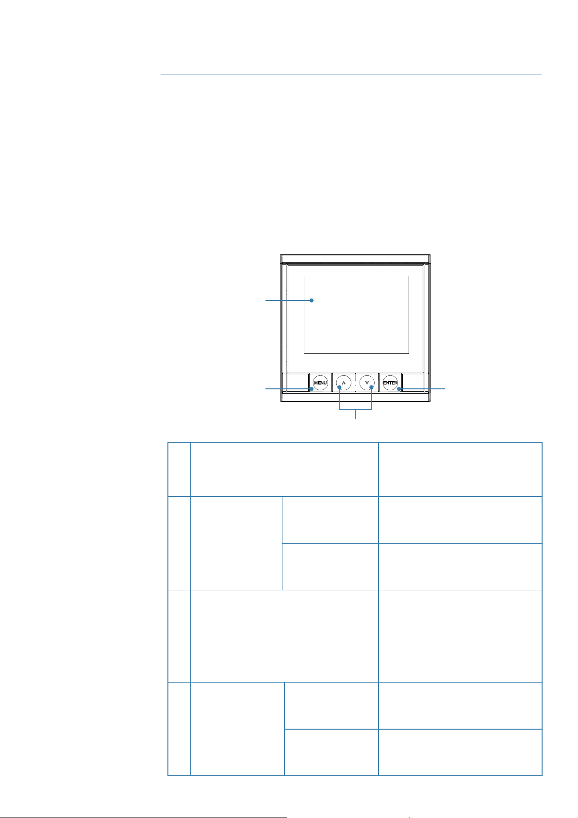
Display and keys
1
2
DISPLAY
1
Short press
2 MENU key
Long press
3 UP/DOWN key
4
3
3.5” Color LCD
320 x 240 Resolution
Page menu / Return
to previous menu
Shortcut to Standby
and Display setup
Scrolls up / down
through menu / set
values / active page
transition
Enter sub menu /
Short press
Con rm selection
4 ENTER key
Shortcut to Enabled
Long press
pages
Simrad IS35 Color Display | Simrad IS35 User manual
| 7
Page 8
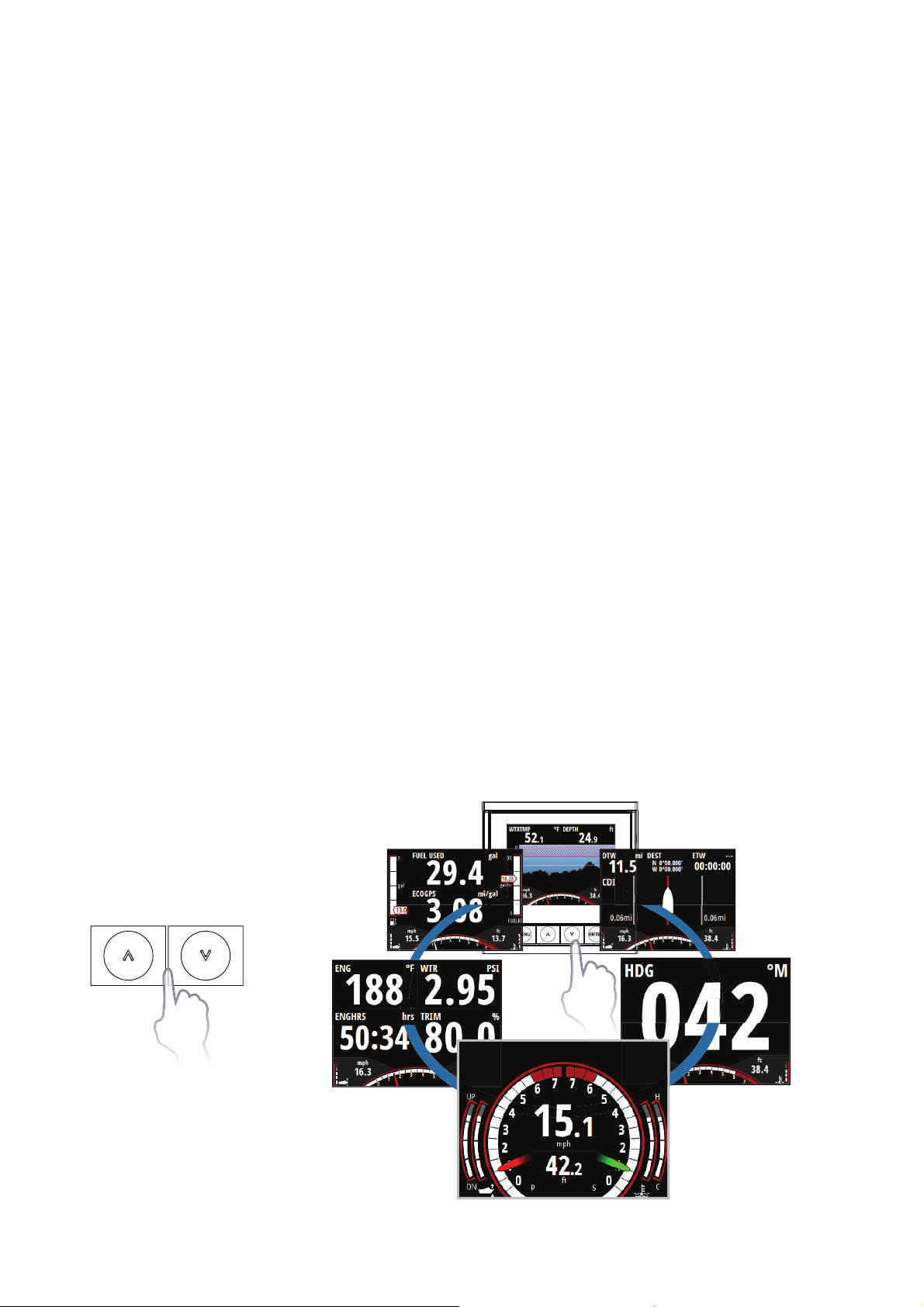
Default display pages
When starting for the rst time, the gauge is set
with ve default pages showing engine and system
information. It is possible to add pages via the Pages
menu and to change the template pages via the
template page sub menu.
The information displayed on xed data pages cannot
be edited by the user. The type of information shown
depends on what devices are connected on the
network.
Note: Data elds are prioritized automatically. Adding
or removing devices from the network may change
which data types are displayed on the gauge.
See the Pages section of this manual for more
information on page setup and con guration.
Page transition
Use the UP/DOWN keys to scroll through the active
pages.
8 |
Simrad IS35 Color Display | Simrad IS35 User manual
Page 9

2
Operation
Menu operation
Page menu
The Page menu options vary from page to page.
Pressing the MENU key once on any page will show
the available menu options.
Note: All page menus have a settings option. Any other
option refers to the current page.
Settings
The Settings menu is where display options, display
settings, system settings, source selection and
calibration can be accessed.
Operation | Simrad IS35 User manual
| 9
Page 10
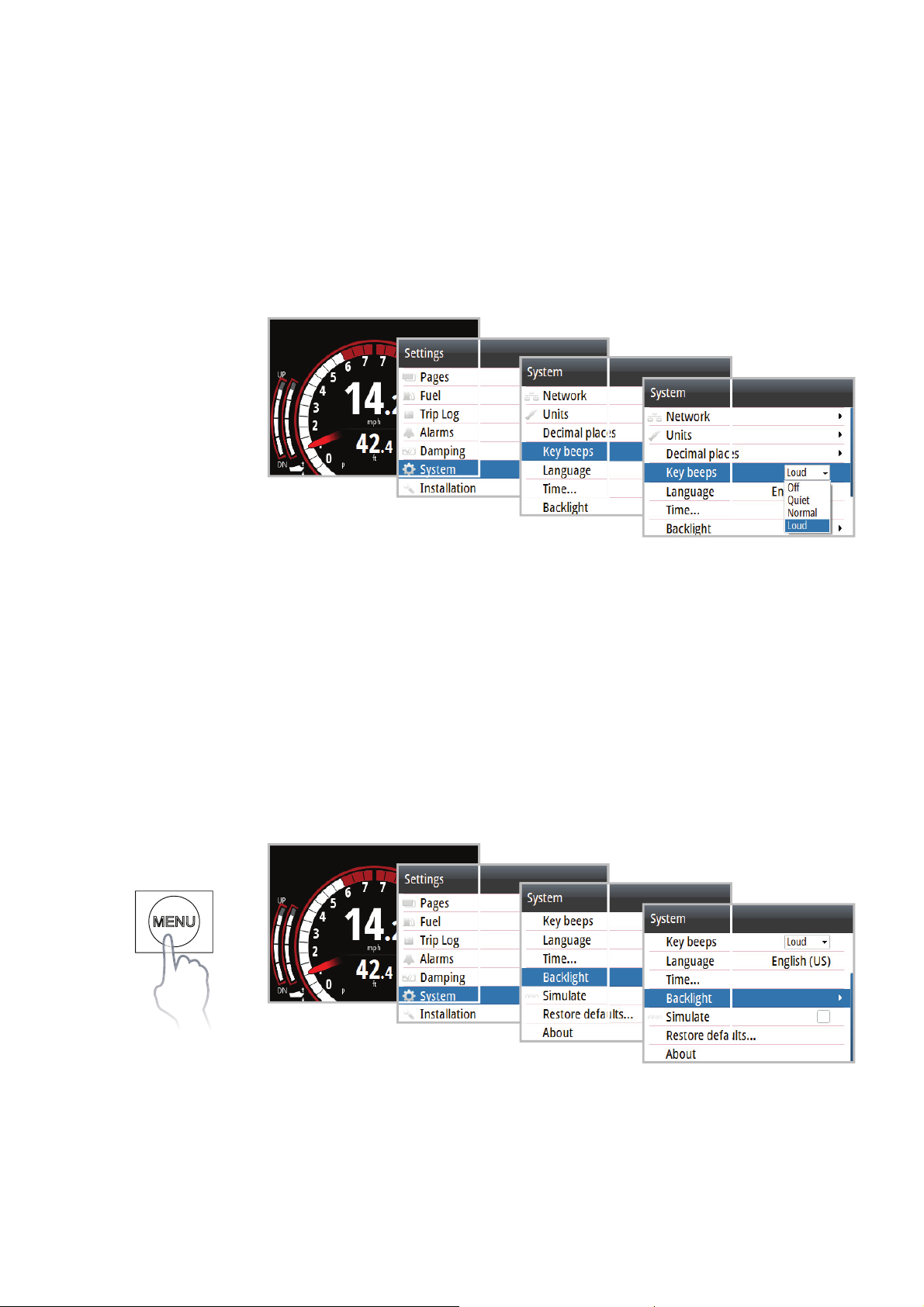
Example menu structure
1. Press the MENU key
2. Use the UP/DOWN and ENTER keys to select and
navigate through the menu options
Example: Access Key beeps dialog via the settings
menu.
Note: Pressing the MENU key once returns you to the
previous menu.
Backlight
There are two methods of adjusting the gauge
backlight.
1. Via the Menu
10 |
Operation | Simrad IS35 User manual
Page 11
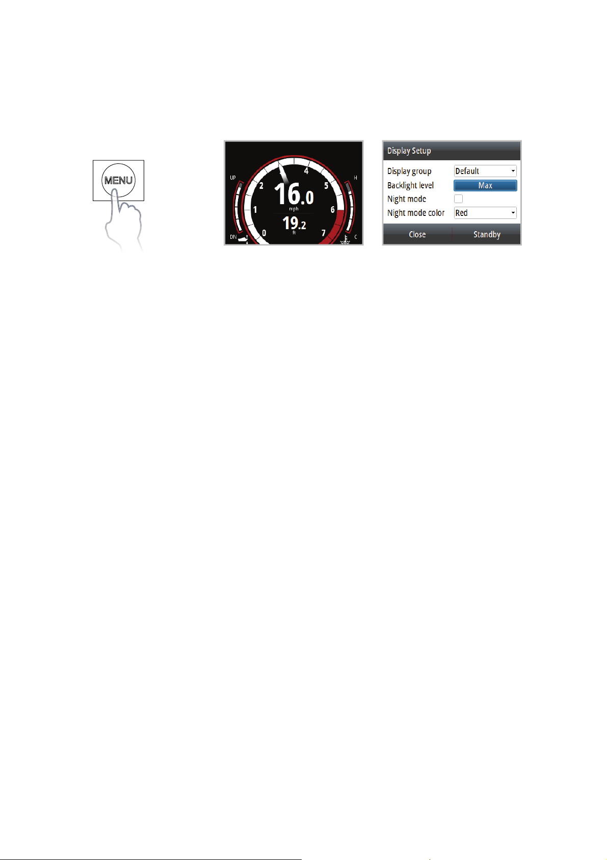
2. Via the Display setup shortcut
Press and hold the MENU key for three seconds to
open the Display setup.
3 secs
Display group
All units in the selected Display group will mirror each
others light settings.
Level
Adjusts the backlight level from Min (10%) to Max
(100%) in 10% increments.
Night mode
Changes the gauge to Night Mode color palette. All
gauges in the selected Display group will also change
to Night Mode.
Note: Gauge night mode cannot be changed via a
Multi-Function Display.
Night mode color
Changes the Night Mode color palette.
Operation | Simrad IS35 User manual
| 11
Page 12
Pages
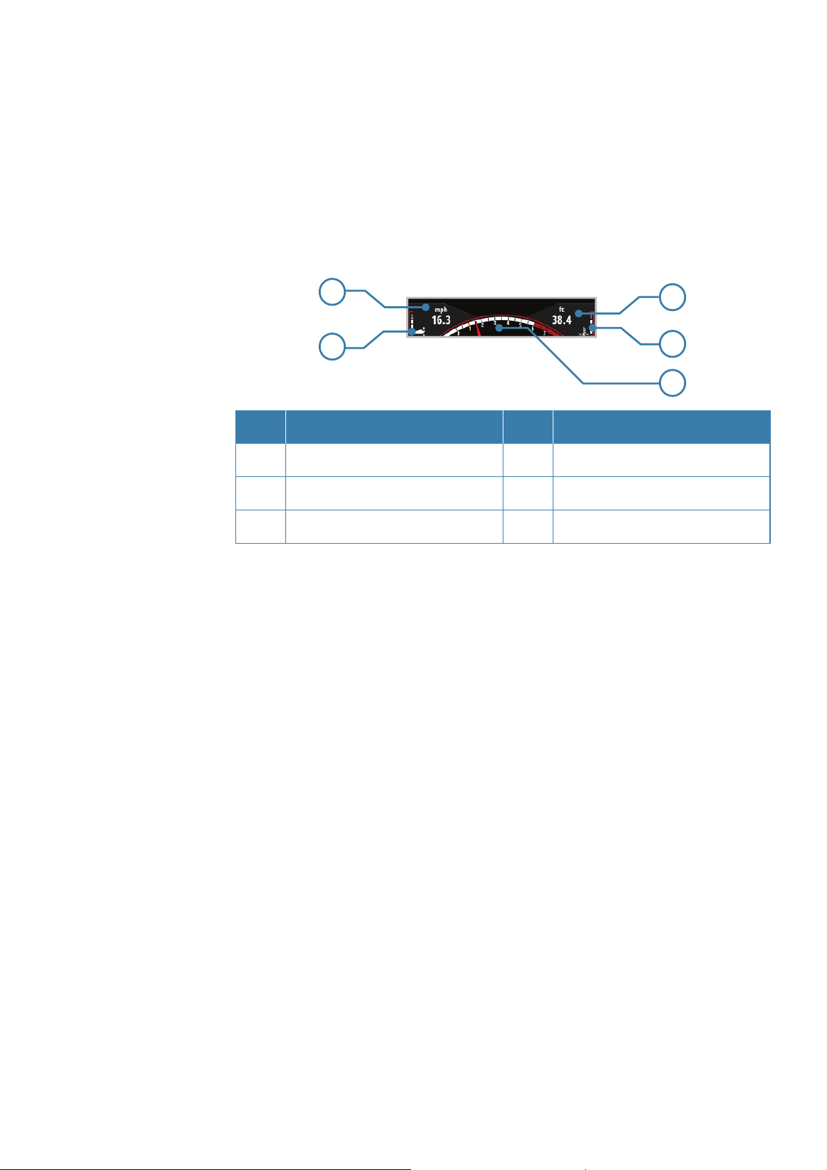
Static gauge
Some pages have a static gauge at the bottom of the
display showing two pieces of dynamic data, engine
trim, temperature and an RPM dial.
1
2
No. Description No. Description
Dynamic data eld 4 Engine temperature
1
2 Engine trim 5 RPM Dial
3 Dynamic data eld
Note: Dynamic data elds on the gauge pages and the
static gauge automatically populate and the data type
shown depends on what devices are on the network.
Static gauge dynamic data eld priority order
3
4
5
1. Speed (Speed Over Ground preferred. Requires GPS,
paddle wheel, Pitot)
2. Depth (Requires depth data on the network)
3. RPM
4. Fuel economy
5. Fuel ow
Note: When data from two engines is displayed, only
RPM, Engine trim and Engine temperature are shown.
12 |
Operation | Simrad IS35 User manual
Page 13
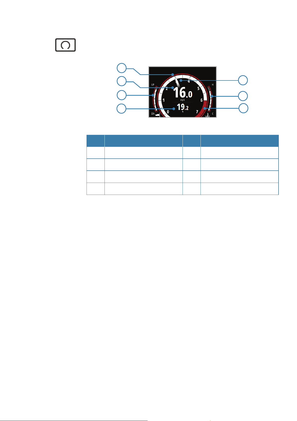
Default xed data pages
Motoring
1
2
3
4
5
6
7
No. Description No. Description
RPM Dial 5 RPM Needle
1
2 Dynamic data eld 6 Engine temp
3 Engine trim 7 RPM Limit
4 Dynamic data eld
Motoring dynamic data eld priority order
1. Speed (Speed Over Ground preferred. Requires GPS,
paddle wheel, Pitot) Depth (Requires depth data on the
network)
2. Vessel fuel economy
3. Vessel fuel rate
Operation | Simrad IS35 User manual
| 13
Page 14
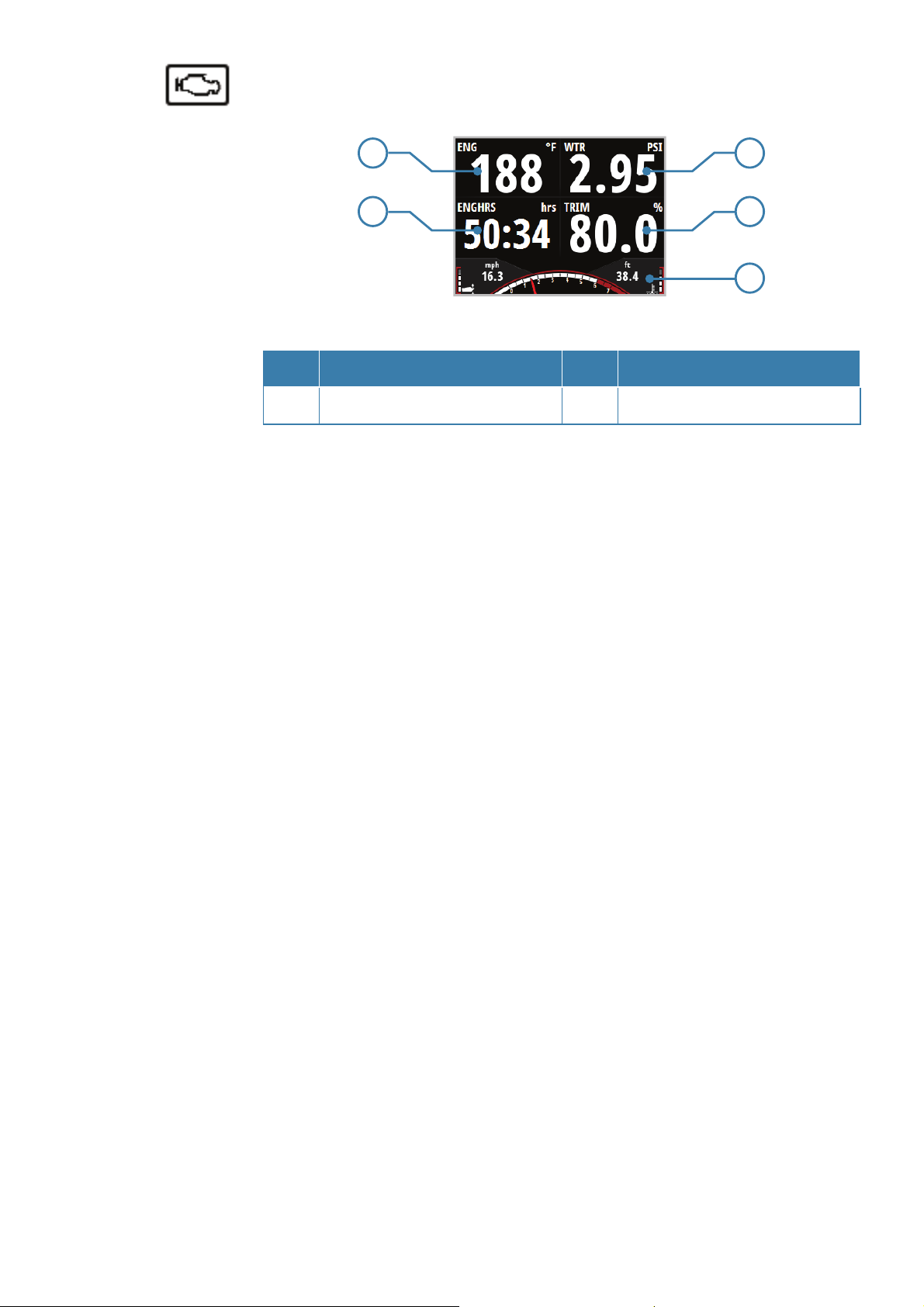
Engine
1
3
42
5
No. Description No. Description
1-4
Dynamic data elds 5 Static gauge
Engine dynamic data eld priority order
1. Alternator voltage
2. Engine temp
3. Engine water pressure (Requires a pressure sensor on
the network)
4. Engine hours
5. Engine trim.
14 |
Operation | Simrad IS35 User manual
Page 15

Fuel economy
1
2
3
4
5
No. Description No. Description
1
Vessel fuel remaining 4 Fuel rate
2 Dynamic data eld 5 Static gauge
3 Fuel used
Fuel dynamic data eld priority order
1. Vessel fuel economy (GPS)
2. Vessel fuel economy (water)
3. Vessel fuel (rate)
Note: Vessel Fuel Remaining will only be shown when
fuel ow data is available and a fuel storage device
such as an EP-85R is on the network.
Operation | Simrad IS35 User manual
| 15
Page 16

Additional xed data pages
Depth history
Note: Requires depth data on the network
1
3
4
2
5
No. Description No. Description
Water temperature 4 Depth alarm limits
1
2 Depth histogram 5 Static gauge
3 Dynamic data eld
Motor steer
Note: Requires a Chartplotter on the network.
1
4
2
5
3
6
7
No. Description No. Description
1
Waypoint position 5 Vessel indicator
2 Distance to waypoint 6 Cross track error limit
3 Cross track error limit 7 Static gauge
4 Estimated time to waypoint
16 |
Operation | Simrad IS35 User manual
Page 17

If the vessel moves out of the cross track error limit,
the gauge will change to show the direction and
distance that the vessel is o course.
Operation | Simrad IS35 User manual
| 17
Page 18

Template pages
Icon Description Page
Single gauge
(with RPM)
2x2 grid
(with RPM)
2x1 grid
(with RPM)
2x2 (bars) grid
(with RPM)
Quad bars
(with RPM)
Single gauge
(full screen)
2x1 grid
(full screen)
18 |
2x2 grid
(full screen)
Operation | Simrad IS35 User manual
Page 19

Enabling / disabling a page
To Enable/Disable a page you need to rst ensure it
has been added to the pages list shown in Replacing/
Adding a page.
1. Press the ENTER key on the desired page to open the
Enabled/Replace dialog
2. Press ENTER to toggle On/O .
Replacing / adding a page
1. Select the page you want to add / replace
2. Press the ENTER key to open the Enabled/Replace
dialog
Operation | Simrad IS35 User manual
| 19
Page 20

3. Select the desired page from the Replace page list
The selected page is shown in the active pages list.
Con guring page data
Once selected a template page can be con gured to
show any available system data.
Note: A template page cannot be edited until it has
been selected and enabled as one of the active display
pages.
1. Select a page that can be changed. I.e. 2x1 grid
2. Press MENU
3. Select Change data
4. Select the desired eld
5. Select the desired data type from the menu options.
20 |
Once selected, a tick appears in the check box and the
gauge will revert to the page.
Operation | Simrad IS35 User manual
Page 21

The desired data now appears in the selected eld.
Before opting to save you can populate other blank
elds by repeating steps 4 and 5.
6. Press MENU
7. Select Save
Note: If a data type is selected but there is no sensor
information on the network, the gauge will show as ---.
AutoScroll
Select AutoScroll from the pages menu.
AutoScroll time can be set between 1 and 10 seconds.
Operation | Simrad IS35 User manual
| 21
Page 22

Trip log
The Trip Log shows trip duration, distance, average
speed and max speed from the time the Trip Log was
started / reset.
Note: Trip information is calculated using GPS or
the paddlewheel if GPS is not present. No Trip Log
information is recorded while the Trip Log is stopped.
Start / Stop Trip Log
Starts / Stops the trip log recording
Reset Trip Log
Resets all trip log information to zero.
22 |
Operation | Simrad IS35 User manual
Page 23

3
Refuelling
Adding fuel for the rst time
To accurately calculate fuel capacity, ll the tank and
select Set to full in the Vessel refuel dialog. Estimating
existing fuel level incorrectly could result in inaccurate
fuel remaining and fuel range calculations.
1. Make sure the vessel setup is complete and the
number of tanks and total fuel capacity is set to the
correct value.
Note: The number of tanks and fuel capacity can
be updated using the vessel setup dialog in the
installation menu, or by using the rst-time start-up
wizard.
2. Go to the Refuel dialog via the Settings menu
Refuelling | Simrad IS35 User manual
| 23
Page 24

Adding fuel
1. Make sure the vessel setup is complete and the
number of tanks and total fuel capacity is set to the
correct value.
2. Enter the amount of fuel added to the tank into the
Amount added section, or select Set to full when
lling the tank to its maximum capacity
Fuel used
The fuel Used dialog shows how much fuel has been
used since last ll, from trip reset and seasonal usage
(continuous recording).
Note: If more than one engine is on the network, then
the Fuel Used data shown is the total for all engines. It
also lists the data for each engine.
24 |
Refuelling | Simrad IS35 User manual
Page 25

Fuel used reset
To access reset to zero options, select Reset at the
bottom of the Fuel Used page. Then select the desired
reset option from the list.
Note: You can reset the total for one engine or all
engines.
Reset option Description
None Returns to Fuel Used page
Trip Reset Trip fuel used only
Seasonal Reset Seasonal fuel used only
Both Reset Trip and Seasonal fuel used
Refuelling | Simrad IS35 User manual
| 25
Page 26

4
Settings
Engine alarms
For engine-speci c alarms, an icon will appear on the
display and remain on while that alarm instance is still
valid.
Note: For dual engines, the alarm icon appears on the
side of the display that the engine is con gured.
Icon Alarm description
Power / Charge indicator
Check engine / General engine faults /
Engine or its related system faults
High engine temperature
Warning - Engine malfunction - Check
26 |
active alarms for available information
Water in fuel
Settings | Simrad IS35 User manual
Page 27

System alarms
If a sensor is connected to the network, you can
enab;e alarms by selecting them from the list in the
Alarm settings menu.
Enabling an alarm (alarm On/O )
Turns an alarm on or o via the Alarm Settings menu.
Settings | Simrad IS35 User manual
| 27
Page 28

Alarms setting status
When an alarm option is highlighted, the Enabled
dialog at the bottom of the page will show the alarm
settings status and alarm limit.
Note: The relevant sensor must be on the network for
the alarm to be enabled.
Check box Description
Alarm disabled
Alarm enabled
Alarm group (multiple alarms). At least
one but not all alarms in the group are
enabled
There is a sub menu with other alarm
groups. Select the next level down in the
menu to show the alarm status
Alarm limits
Some alarms may feature an adjustable limit. Select
the alarm and set the limit in the Alarm Settings menu.
28 |
Settings | Simrad IS35 User manual
Page 29

Alarm indication
The alarm is triggered if any settings are exceeded.
Alarms are indicated with an alarm text and an audible
alarm (optional).
Acknowledging an alarm
An alarm is acknowledged by pressing the ENTER key.
This removes the alarm noti cation and silences the
alarm. In some cases the alarm icon remains on the
gauge until the fault is resolved.
Active alarms
Lists active alarms on the network. These alarms will
be present until the alarm instance is cleared.
Settings | Simrad IS35 User manual
| 29
Page 30

Alarm history
The alarm history can be accessed via the Alarm
History menu. This stores alarm messages until they
are manually cleared.
Alarm details
Select an alarm instance to show more details of that
speci c occurrence and the action taken.
Clear Alarm History
1. Open Alarm History list
2. Press ENTER
3. Select Clear all
30 |
Settings | Simrad IS35 User manual
Page 31

Engine alarm settings
Set all Engine Alarms on or o . If multiple engines are
in use, Custom Setting can be used to select which
engines alarms are on or o .
Setting Description
O All alarms for all engines are o
All All alarms for all engine are on
Individually select which engines
Custom
alarms will be all on or all o
Alarm siren
When enabled, an audible alarm sounds when an
instance is triggered.
Settings | Simrad IS35 User manual
| 31
Page 32

Damping
Damping rate a ects how frequently the data is
updated; the greater the damping value, the smoother
the number change will be, but the change will also
be slower..
System
From the System menu there are several display and
system options available.
Network
Before the system can be used, the data sources need
to be con gured.
32 |
Sources
A data source can be a sensor or a device connected to
the network that provide information and commands
to other networked devices. The data sources are
normally con gured the rst time the system is turned
on. It should only be necessary to update this data if
Settings | Simrad IS35 User manual
Page 33

a new source is added, data is missing or removed, a
source has been enabled/disabled, a sensor replaced
or after a network reset.
Auto Select
The Auto Select option looks for all sources connected
to the network. If more than one source is available for
each item, the gauge automatically selects from the
internal device priority list.
Device list
Shows a list of all devices connected to the Network.
Selecting a device in this list brings up additional
details and actions.
Settings | Simrad IS35 User manual
| 33
Page 34

Con gure
All units come pre-con gured but they can be
modi ed once connected to the network. The
example below shows how to con gure the engine
location.
Note: Con guring the engine location correctly is
important when more than one engine is on the
network.
Some devices show additional options speci c to
the device. For example the Calibrate option, to
allow easy setup of a device. Calibration options vary
depending on the device.
Diagnostics
NMEA2000 Bus diagnostic data on the network.
Units
Set the unit of measurement for how you want the
data to be displayed.
34 |
Settings | Simrad IS35 User manual
Page 35

Decimal places
Set the number of decimal places for the boat speed
and sea temperature display.
Language
Set the preferred language for the gauge.
Note: This is not a network function. You need to
change all gauges separately.
Note: The unit automatically restarts once the
language is selected.
Time
Set the preferred time / date format and the local time
o set.
Settings | Simrad IS35 User manual
| 35
Page 36

Simulate
Sends simulated data to the gauge.
Note: All other gauges on the network continue to
display the current boat data and do not change to
simulate mode. A simulate warning box ashes on and
o at the top of the display.
Restore defaults
Restore all system settings of the gauge to factory
defaults.
Note: This is not a network function. This only resets
and deletes history on the individual gauges selected.
36 |
Forced factory reset
If the gauge does not respond to the normal restore
procedures, press and hold the UP / DOWN keys while
powering the unit on. A beep signi es the reset has
been completed.
Settings | Simrad IS35 User manual
Page 37

Installation
Via the Installation menu, access Vessel Setup, Engine
Display Setup, Gauge limits and Pop-ups setup
dialogs. Save and restore user data, upgrade the
gauge and remote units software via the Files dialog.
Vessel setup
Set the number of engines, fuel tanks and total fuel
capacity.
Note: These settings are applied to all devices on the
network.
Settings | Simrad IS35 User manual
| 37
Page 38

Engine display setup
A maximum of two engine’s data can be shown on
each gauge. If the number of engines is set to two or
more in the Vessel Setup, select which engine’s data
should be displayed via the Engine Display Setup.
Gauge limits
Set the RPM and vessel fuel rate limits.
Note: These limits are a visual guide on the display and
do not set alarms.
38 |
Settings | Simrad IS35 User manual
Page 39

Example below shows rev limit start line set to 6000
RPM.
Pop-Up setup
Set the threshold and duration that pop-up
information will be displayed when the engine trim,
transmission and lever control is adjusted.
Pop-ups appear when the gauge sees a change in
data that is greater than the set threshold.
Settings | Simrad IS35 User manual
| 39
Page 40

Files
Access an attached USB device, import/export system
settings, template page, vessel setup. Upgrade the
software on the engine gauge and remote devices.
Note: Each gauge on the network needs to be
upgraded individually.
Connecting a Micro-USB device
1. Remove USB cover from the rear of the gauge
2. Insert a USB Micro USB adaptor and mass storage
device
40 |
Settings | Simrad IS35 User manual
Page 41

Export system settings
1. Insert a USB Micro USB adaptor and mass storage
device
2. Go to the Files menu
3. Select System Settings
4. Press ENTER to export system settings to the USB mass
storage device
Import system settings
1. Insert a USB Micro USB adaptor and mass storage
device
2. Go to the Files menu
3. Select the Settings.iset le from the USB memory,
the details dialog will appear. Press ENTER to con rm
import
Warning: Importing system settings
overwrites all existing system settings and
restarts the gauge!
Settings | Simrad IS35 User manual
| 41
Page 42

Software
About
Shows the device information and current software
version installed on the gauge. Press the MENU key to
exit.
To show the current version of software on a remote
device go to the Device List and select the relevant
device.
Remote device software upgrade
Update the software for NMEA 2000 sensors.
1. Verify software version via the Device List
42 |
2. Save the update le to a USB mass storage device
3. Connect portable storage device to micro USB slot
4. Select the update le from the USB memory
5. When the details dialog appears, press ENTER
6. Press ENTER again to con rm upgrade
Settings | Simrad IS35 User manual
Page 43

7. The upgrade progress dialog will appear. Press ENTER
once upgrade is complete
IS35 Color Display software upgrade
1. Verify software version via the About dialog
2. Save the latest .upd le to a USB mass storage device
3. Ensure the gauge power is o
4. Insert USB mass storage device via the USB adaptor
5. Turn the power on. The gauge will automatically begin
the upgrade procedure
6. A message will appear on the gauge once the update
is complete
7. Remove the USB device and replace the USB cover
Warning: Do not remove the USB storage
device until prompted to do so once
the update is complete. Removing the
USB storage device before the update is
complete may cause the gauge to become
unresponsive or require repair!
Settings | Simrad IS35 User manual
| 43
Page 44

Maintenance
5
If the gauge needs to be cleaned, use fresh water and
a mild soap solution (not a detergent). Avoid using
chemical cleaners and hydrocarbons, such as diesel,
petrol etc.
Checking the keys
Make sure that none of the keys are stuck in the down
position.
Checking the connector
The connector should be checked by visual inspection
only. Ensure that the cable is connected correctly and
the USB port cover is in place.
44 |
Maintenance | Simrad IS35 User manual
Page 45

6
Speci cations
Weight 0.28 kg (0.60 lbs)
Power
consumption
Network load
Color Black
Display
Size 3.5” (Diagonal) 4:3 Aspect ratio
Type Transmissive TFT-LCD
Resolution 320 x 240 pixels
Illumination White (day mode)
Red / Green / Blue (night mode)
Environmental
Protection
Maximum 10 gauges
White LED back-light
130 mA at 13.5V
LEN 3
IPX7
Safe distance to
0.3 m (1.0 ft.)
compass
Temperature
Operating
Storage -25 to +65 ºC (-13 to +149 ºF)
-15C to +55 ºC (+5 to +131 ºF)
Speci cations | Simrad IS35 User manual
| 45
Page 46

*988-10712-001*
www.simrad-yachting.com
 Loading...