

Page 1
ENGLISH
HS70
User Manual
www.simrad-yachting.com
Page 2

Page 3

| i
Preface | HS70 User Manual
Preface
Disclaimer
As Navico is continuously improving this product, we retain the right to make changes to the
product at any time which may not be refl ected in this version of the manual. Please contact
your nearest distributor if you require any further assistance.
It is the owner’s sole responsibility to install and use the instrument and transducers in a
manner that will not cause accidents, personal injury or property damage. The user of this
product is solely responsible for observing safe boating practices.
NAVICO HOLDING AS AND ITS SUBSIDIARIES, BRANCHES AND AFFILIATES DISCLAIM ALL
LIABILITY FOR ANY USE OF THIS PRODUCT IN A WAY THAT MAY CAUSE ACCIDENTS, DAMAGE
OR THAT MAY VIOLATE THE LAW.
Governing Language: This statement, any instruction manuals, user guides and other
information relating to the product (Documentation) may be translated to, or has been
translated from, another language (Translation). In the event of any confl ict between any
Translation of the Documentation, the English language version of the Documentation will be
the offi cial version of the Documentation.
This manual represents the product as at the time of printing. Navico Holding AS and its
subsidiaries, branches and affi liates reserve the right to make changes to specifi cations
without notice.
Compliance
The HS70 complies with the following regulations:
• FCC Part 15, Subpart B
• CE compliant with R&TTE directive
For further compliance information please refer to our website: www.simrad-yachting.com
Copyright
Copyright © 2011 Navico Holding AS.
Warranty
The warranty card is supplied as a separate document.
In case of any queries, refer to the our website: www.simrad-yachting.com
About this manual
This manual is a reference guide for installing and using the Simrad HS70.
Important text that requires special attention from the reader is emphasized as follows:
Note: Used to draw the reader’s attention to a comment or some important information.
Warning: Used when it is necessary to warn personnel that they
should proceed carefully to prevent risk of injury and/or damage to
equipment/personnel.
Page 4

ii |
Contents | HS70 User Manual
Contents
1 Introduction
1 Overview
1 Parts
2 Installation
2 Mounting Location
2 Mounting Orientation
3 Mounting Options
5 Connecting the cable
5 Ports
7 Default Parameters
8 Operation
8 GPS Overview
8 HS70 Overview
10 Troubleshooting
11 Parts list
11 Included in package
11 Access o r i e s
11 Spare parts
12 Speci cations
12 TGPS sensor specifi cations
12 Communication specifi cations
13 Power specifi cations
13 Me chan ical sp e cifi cati ons
13 Environmental specifi cations
14 HS70 Dimensions
15 PGNs with the HS70 in NMEA 2000 mode
18 NMEA 0183 messages
Page 5

| 1
Introduction | HS70 User Manual
Introduction
Overview
The HS70 is a complete GPS compass and positioning system in a single enclosure that
requires only one power/data cable connection. With its NMEA 2000 and NMEA 0183 support
and ease of installation, the HS70 is the perfect solution for marine applications.
The HS70 is an integrated system that houses the following:
• Dual integrated GPS antennas
• Power supply
• Single axis gyro
• Tilt sensor on each axis (X and Y axes)
• Standard NMEA 2000 port (cable to be ordered separately)
• Standard NMEA 0183 port (cable to be ordered separately)
The gyro and tilt sensors are present to improve system performance and to provide backup
heading information in the event that a GPS heading is not available due to signal blockage.
The HS70’s GPS antennas are separated by 27.5 cm between their phase centers, resulting
in better than 0.75° rms heading performance. The HS70 provides heading and positioning
updates of up to 20 Hz and delivers positioning accuracy of better than 1.0 m 95% of the time
when using diff erential GPS corrections from Space Based Augmentation Systems (SBAS).
Parts
An HS70 installation requires the following parts:
Part Name Qty
HS70 receiver 1
NMEA 2000 or NMEA 0183 cable (not included, must be ordered separately) 1
4 fastening bolts and washers, M8 for fi xed or pole mount (not included) 4
Plastic wraps for cable securing (not included) -
1
Page 6
2 |
Installation | HS70 User Manual
Installation
Mounting Location
This section provides information on determining the best location for the HS70.
GPS Reception
When considering where to mount the HS70, consider the following GPS reception
recommendations:
• Consider GPS (and hence SBAS) reception, ensuring there is a clear view of the sky available
to the HS70 so the GPS and SBAS satellites are not masked by obstructions that may reduce
system performance
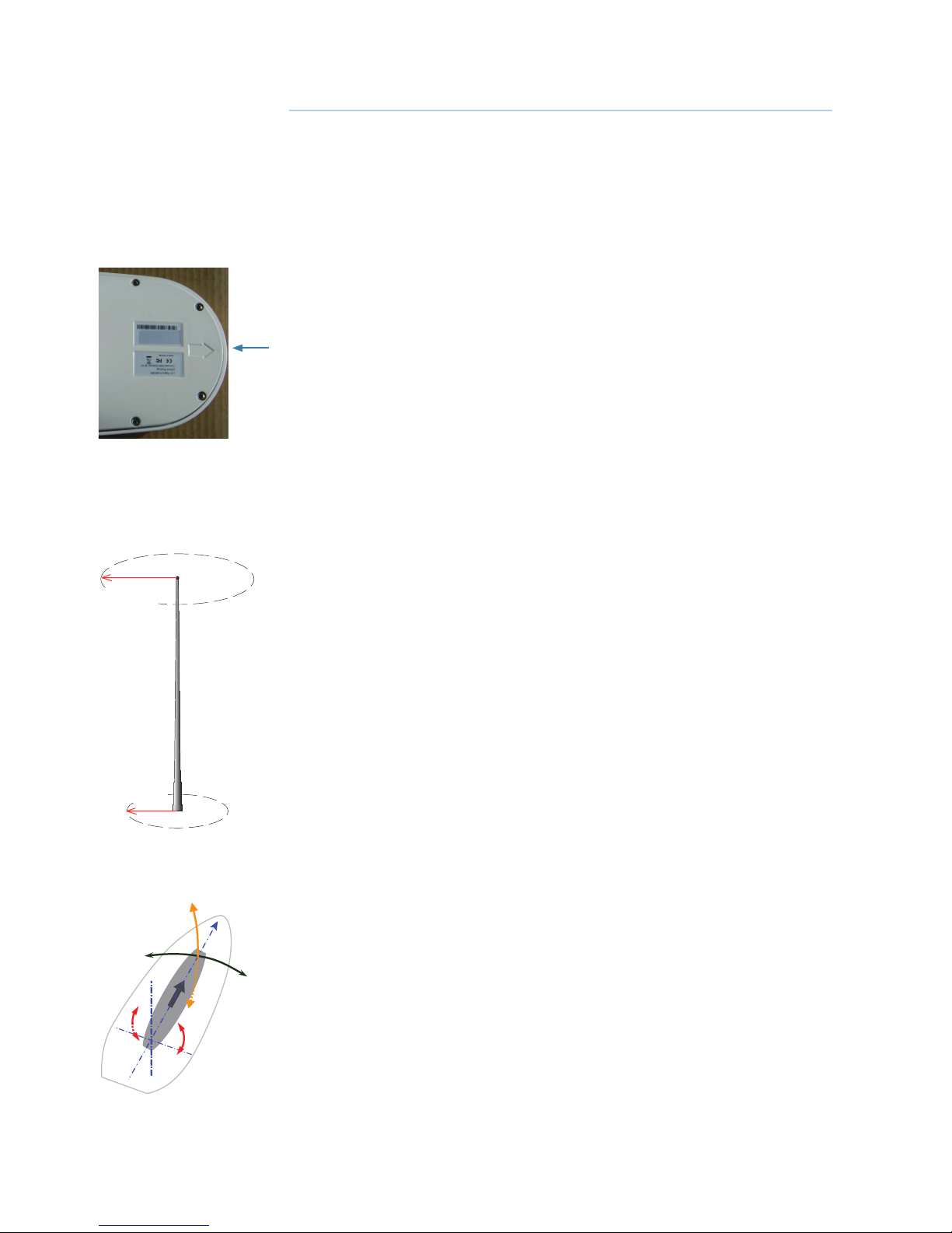
• Since the HS70 computes a position based on the internal primary GPS antenna element,
mount the HS70 where you desire a position with respect to the primary GPS antenna
(located on the end opposite the recessed arrow on the underside of the enclosure)
• Locate any transmitting antennas away from the HS70 (refer illustration below) to ensure
tracking performance is not compromised, giving you the best performance possible
• Make sure there is enough cable length to route into the vessel to reach a breakout box,
terminal strip or NMEA 2000 T-connector
• Do not locate the antenna where environmental conditions exceed those specifi ed in
“Specifi cations” on page 12.
VHF Interference
VHF interference from such devices as cellular phones and radio transmitters may interfere
with GPS operation. For example, if installing the HS70 near marine radios consider the
following:
• VHF marine radio working frequencies (Channels 1 to 28 and 84 to 88) range from 156.05 to
157.40 MHz. The L1 GPS working center frequency is 1575.42 MHz. The bandwidth is +/- 2 MHz
to +/- 10 MHz, which is dependent on the GPS antenna and receiver design
• VHF marine radios emit strong harmonics. The 10th harmonic of VHF radio, in some channels,
falls into the GPS working frequency band, which may cause the SNR of GPS to degrade
signifi cantly
• The radiated harmonic signal strength of diff erent brands/models varies
• Follow VHF radio manufacturers’ recommendations on how to mount their radios and what
devices to keep a safe distance away
• Handheld 5 W VHF radios may not provide suitable fi ltering and may interfere with the HS70’s
operation if too close
Ensure there are no nearby devices that may cause VHF interference. Use minimum distances
from nearby VHF antenna as shown on the illustration.
Mounting Orientation
The HS70 outputs heading, pitch, and roll readings. However, the relation of the antennas
to the boat’s axis determines whether you will need to enter a heading off set. The primary
antenna is used for positioning and the primary and secondary antennas, working in
conjunction, output heading, pitch, and roll values.
Mount the HS70 parallel to, and along the centerline of, the axis of the boat. This provides a
true heading. In this orientation:
• You can enter a heading off set in a Simrad compatible head unit (AP24, AP28, AP70, AP80, IS20
Graphic/Combi) to calibrate the physical heading to the true heading of the vessel
• You will have an off set in the pitch/roll output if the unit is not installed in a horizontal plane
The fi gure shows recommended orientation and resulting signs of heading (H), pitch (P) and
roll (R) values.
1.5 m (4.9 ft
radius
at top
1.0 m (3.3 ft)
radius
at base
+H
+R
-R
-H
-P
+P
P
S
2
Page 7

| 3
Installation | HS70 User Manual
HS70 Alignment
The top of the HS70 enclosure incorporates sight design features to help you align the
enclosure with respect to your vessel.
To use the sights, center the small post on the opposite side of the enclosure from you, within
the channel made in the medallion located in the center of the enclosure top as shown in the
fi gures below.
Alignment accuracy when
looking through the long site is
approximately +/- 1°
Alignment through the short
site is approximately +/- 2.5°
Mounting Options
The HS70 allows for two diff erent mounting options: fi xed mount and pole mount. Refer
“HS70 Dimensions” on page 14.
• Flush mount - The bottom of the HS70 contains four M8 holes for fl ush mounting the unit to
a fl at surface
• Pole mount - The bottom of the HS70 contains a mounting hole (1” thread, 0.9” depth) for
easy pole mounting. Hand tighten until snug (do not overtighten). The set screws on the long
sides of the base allow you to secure the HS70 in place (3/16” Allen wrench not included)
Note: Mounting accessories not included.
Cable mounting considerations
Before mounting the HS70 consider the following regarding power/data cable routing:
• Cable must reach an appropriate power source
• Cable may connect to a data storage device, computer, or other device that accepts GPS data
• Avoid running the cable in areas of excessive heat
• Keep cable away from corrosive chemicals
• Do not run the cable through door or window jams
• Keep cable away from rotating machinery
• Do not crimp or excessively bend the cable
• Avoid placing tension on the cable
• Remove unwanted slack from the cable at the HS70 end
• Secure along the cable route using plastic wraps
Warning: Improperly installed cable near machinery can be dangerous.
Fixed Mount
The bottom of the HS70 contains four holes for fl ush mounting the unit to a fl at surface. See
fi gure below. The fl at surface may be something you fabricate per your installation, an off -theshelf item (such as a radar mounting plate), or an existing surface on your vessel.
Note: HS70 does not include the mounting surface hardware. You must supply the appropri-
ate fastening hardware required to complete the installation of the HS70.
Page 8

4 |
Installation | HS70 User Manual
Note: You do not necessarily need to orient the antenna precisely as you can enter a software
off set to accommodate for any off set in heading measurement due to installation.
Before x mounting the HS70
• Choose a location that meets the mounting location requirements
• Use the mounting template, mark and drill the mounting holes as necessary for the mounting
surface
• Attach the cable to the HS70 and secure the cable
Fix mounting the HS70
1. Mark the mounting hole centers on the mounting surface.
2. Place the HS70 over the marks to ensure the planned hole centers align with the true hole centers
(adjusting as necessary).
3. Use a center punch to mark the hole centers.
4. Drill the mounting holes with a 9 mm bit appropriate for the surface.
5. Place the HS70 over the mounting holes and insert the mounting screws through the bottom of the
mounting surface and into the HS70.
Warning: When installing the HS70, hand tighten only. Damage resulting from
overtightening is not covered by the warranty.
Pole Mount
Keep the following in mind when using a pole mount:
• Mounting hole is 1” thread, 0.9” depth
• Hand tighten until snug (do not overtighten) while ensuring correct orientation
• Use the set screws on the long sides of the base to secure the HS70 in place (3/16” Allen
wrench not included)
Warning: Overtightening may damage the system. This is not covered under
warranty.
Before pole mounting the HS70
• Install the HS70 parallel with the vessel’s axis.
• Choose a location that meets the mounting location requirements.
• Attach the cable to the HS70 and secure the cable.
Page 9

| 5
Installation | HS70 User Manual
Connecting the cable
1. Align the cable connector keyway or the NMEA 2000 adapter with the HS70 connector key
2. Rotate the cable ring clockwise until it locks. The locking action is fi rm, but you will feel a positive “click”
when it has locked
3. Securing the cable
Ports
NMEA 2000 Port
Powering the HS70 when used in a NMEA 2000 installation
To power the unit via NMEA 2000 connection, follow the standard procedure for powering of
a NMEA 2000 network.
Connecting the HS70 to External Devices
For connecting NMEA 2000 devices, plug the serial-to-NMEA 2000 adapter into the HS70 and
then attach a standard NMEA 2000 dropline cable to the adapter.
Insert the 12-pin connector of the adapter into the male end of the 12-pin connector on the
HS70 by aligning the keys. Secure the adapter to the unit using the supplied screws (machine,
8-32, ½”, PPHC, SS) and washer (washer, fl at, #8, SS).
Refer “PGNs with the HS70 in NMEA 2000 mode” on page 15.
NMEA 0183
The HS70 off ers position, heading, rate of turn, time COG and SOG data, via NMEA 0183 port.
In addition to outputting data, these ports are used for fi rmware upgrades.
Refer “NMEA 0183 messages” on page 18.
Powering the HS70 when used in a NMEA 0183 installation
For best performance use a clean and continuous power supply. The HS70 power supply
features reverse polarity protection but will not operate with reverse polarity.
See “Power specifi cations” on page 13 for complete power specifi cations.
Before you power up the HS70 you must terminate the wires of the power cable as required.
There are a variety of power connectors and terminals on the market from which to choose,
depending on your specifi c requirements.
Warning: Do not apply a voltage higher than 36 VDC. This will damage the receiver
and void the warranty.
To interface the HS70 power cable to the power source:
• Connect the red wire of the cable’s power input to DC positive (+)
• Connect the black wire of the cable’s power input to DC negative (-)
The HS70 will start when an acceptable voltage is applied to the power leads of the extension
cable.
The HS70’s power supply is isolated from the communication lines and the PC-ABS plastic
enclosure isolates the electronics mechanically from the vessel (addressing the issue of vessel
hull electrolysis).
Page 10
6 |
Installation | HS70 User Manual
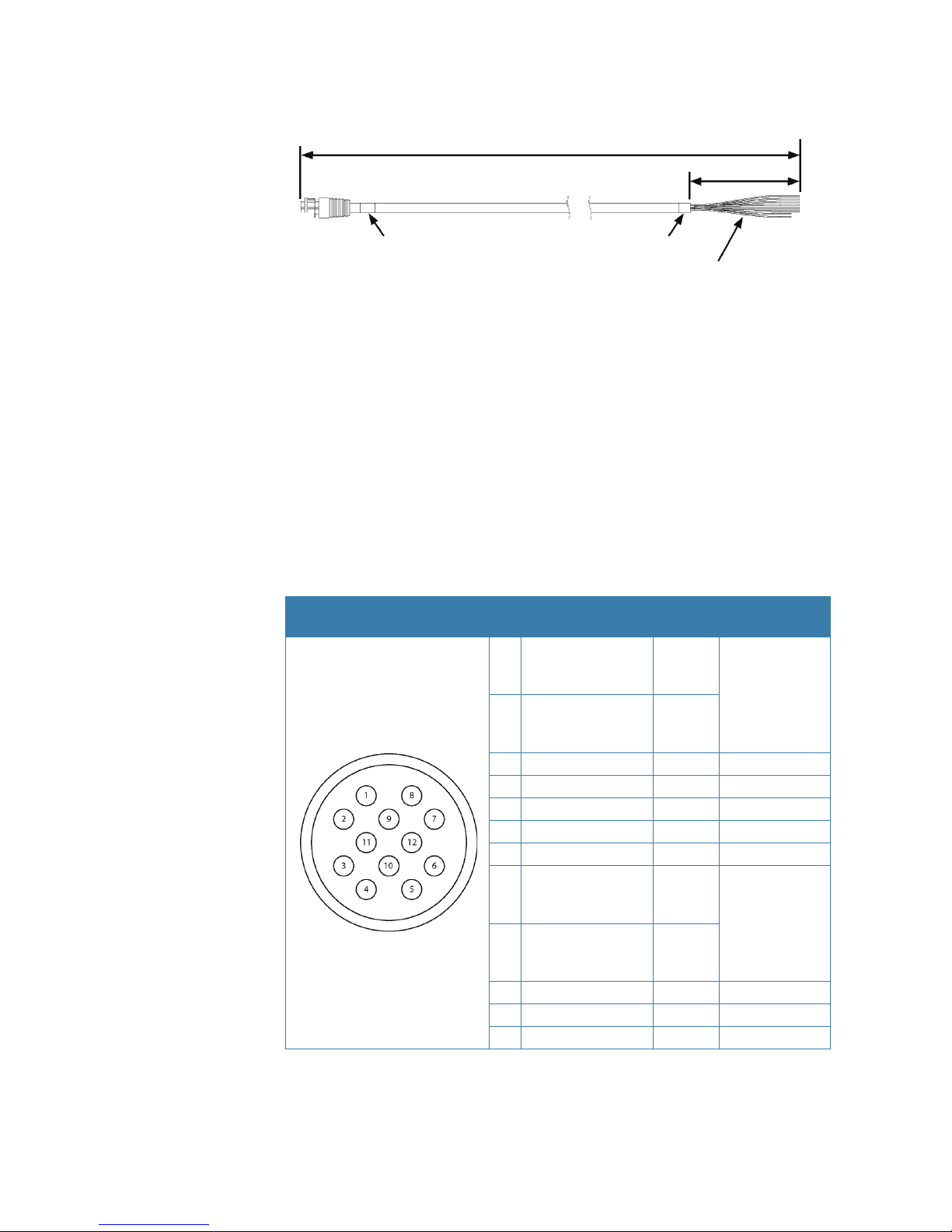
Power/Data Cable Considerations
The HS70 uses a single 15 m (49 ft) cable for power and data input/output.
The receiver end of the cable is terminated with an environmentally sealed 12-pin connection
while the opposite end is unterminated and requires fi eld stripping and tinning.
Depending on the application and installation needs, you may need to shorten this cable.
However, if you require a longer cable run than 15 m, you can bring the cable into a break-out
box that incorporates terminal strips, within the vessel.
When lengthening the cable keep the following in mind:
• To lengthen the serial lines inside the vessel, use 20-gauge twisted pairs and minimize the
additional wire length.
• When lengthening the power input leads to the HS70, ensure the additional voltage drop
is small enough that your power system can continue to power the system above the
minimum voltage of the system. Wire of 18-gauge or larger should also be used.
• Minimize RS-232 cable length to ensure reliable communication
Power/Data Cable Pinout Speci cations
Pin
Function Wire
Color
Comments
1
Port C, RS-232
female DB9 pin 2,
device out
White
NMEA 2000 only
2
Port C, RS-232
female DB9 pin 3,
device in
Green
3 N/C N/C
4 N/C N/C
5 Power input Red
6 N/C N/C
7 Signal ground Yellow
8
Port A, RS-232
female DB9 pin 3,
device in
Brown
NMEA 0183 only
9
Port A, RS-232
female DB9 pin 2,
device out
Blue
10 Power ground Black
11 CH_GND Drain
12 N/C N/C
Page 11

| 7
Installation | HS70 User Manual
Default Parameters
The table below provides details on the default port settings, available baud rates, diff erential
age, elevation mask, and default diff erential mode.
Port Baud Rate NMEA Messages
Port A
(NMEA 0183)
4800 GGA, HDT, ROT, VTG, ZDA
Port C
(RS-232)
57600 None, used for serial to NMEA 2000 adapter
Power
RED (+)
BLK (-)
6 - 36 V DC
Page 12

8 |
Operation | HS70 User Manual
Operation
GPS Overview
For your convenience, both the GPS and SBAS operation of the HS70 features automatic
operational algorithms. When powered for the fi rst time, the HS70 performs a “cold start,”
which involves acquiring the available GPS satellites in view and the SBAS diff erential service.
GPS Operation
The GPS receiver is always operating, regardless of the DGPS mode of operation. The following
sections describe the general operation of the HS70’s internal GPS receiver.
Note: Diff erential source and status have no impact on heading, pitch, or roll. They only have
an impact on positioning and heave.
Automatic Tracking
The HS70’s internal GPS receiver automatically searches for GPS satellites, acquires the signals,
and manages the navigation information required for positioning and tracking.
Receiver Performance
The HS70 works by fi nding four or more GPS satellites in the visible sky. It uses information
from the satellites to compute a position within 4.0 m. Since there is some error in the
GPS data calculations, the HS70 also tracks a diff erential correction. The HS70 uses these
corrections to improve its position accuracy to better than 1.0 m.
There are two main aspects of GPS receiver performance:
• Satellite acquisition
• Positioning and heading calculation
When the HS70 is properly positioned, the satellites transmit coded information to the
antennas on a specifi c frequency. This allows the receiver to calculate a range to each
satellite from both antennas. GPS is essentially a timing system. The ranges are calculated
by timing how long it takes for the signal to reach the GPS antenna. The GPS receiver uses a
complex algorithm incorporating satellite locations and ranges to each satellite to calculate
the geographic location and heading. Reception of any four or more GPS signals allows the
receiver to compute three-dimensional coordinates and a valid heading.
Di erential Operation
The purpose of diff erential GPS (DGPS) is to remove the eff ects of atmospheric errors, timing
errors, and satellite orbit errors, while enhancing system integrity. Autonomous positioning
capabilities of the HS70 will result in positioning accuracies of 4.0 m 95% of the time. In order
to improve positioning quality to better than 1.0 m 95%, the HS70 is able to use diff erential
corrections received through the internal SBAS demodulator.
Automatic SBAS Tracking
The HS70 automatically scans and tracks SBAS signals without the need to tune the receiver.
The HS70 features two-channel tracking that provides an enhanced ability to maintain a lock
on an SBAS satellite when more than one satellite is in view. This redundant tracking approach
results in more consistent tracking of an SBAS signal in areas where signal blockage of a
satellite is possible.
HS70 Overview
The HS70 provides accurate and reliable heading and position information at high update
rates. To accomplish this task, the HS70 uses a high performance GPS receiver and two
antennas for GPS signal processing. One antenna is designated as the primary GPS antenna
and the other is the secondary GPS antenna. Positions computed by the HS70 are referenced
to the phase center of the primary GPS antenna. Heading data references the vector formed
from the primary GPS antenna phase center to the secondary GPS antenna phase center.
3
Page 13

| 9
Operation | HS70 User Manual
The heading arrow located on the bottom of the HS70 enclosure defi nes system orientation.
The arrow points in the direction the heading measurement is computed (when the antenna
is installed parallel to the fore-aft line of the vessel). The secondary antenna is directly above
the arrow.
Note: The HS70 moving base station algorithm only uses GPS to calculate heading. Diff eren-
tial corrections are not used in this calculation and will not aff ect heading accuracy.
Supplemental Sensors
The HS70 has an integrated gyro and two tilt sensors. The gyro and tilt sensors are enabled
by default. Each supplemental sensor may be individually enabled or disabled. Both
supplemental sensors are mounted on the printed circuit board inside the HS70.
The sensors act to reduce the startup and re-acquisition times. This improves the reliability
and accuracy of selecting the correct heading solution by eliminating other possible,
erroneous solutions. The table below provides a sensor operation summary.
Feature Normal Operation Coasting (no GPS)
Heading GPS Gyro
Heave GPS None
Pitch GPS Inertial sensor
Roll Inertial sensor Inertial sensor
Page 14

10 |
Troubleshooting | HS70 User Manual
Troubleshooting
Sympton Possible Solution
Receiver fails to
power
• Verify polarity of power leads
• Check integrity of power cable connectors
• Check power input voltage (6 to 36 VDC)
• Check current restrictions imposed by power source (minimum
available should be > 1.0 A)
No data from HS70 • Check receiver power status to ensure the receiver is powered
(an ammeter can be used for this)
• Ensure the baud rate (4800) of the HS70 matches that of the
receiving device
• Check integrity and connectivity of power and data cable
connections
Random data from
HS70
• Ensure the baud rate of the HS70 matches that of the remote
device
No GPS lock • Verify the HS70 has a clear view of the sky
• Verify the lock status of GPS satellites in the Simrad compatible
head unit (refer separate documentation)
No SBAS lock • Verify the HS70 has a clear view of the sky
Note: SBAS lock is only possible if you are in an appropriate SBAS
region; currently, there is limited SBAS availability in the southern
hemisphere.
No heading or
incorrect heading
value
• Heading is from primary GPS antenna to secondary GPS
antenna, so the arrow on the underside of the HS70 should be
directed to the bow side
• Monitor the number of satellites and SNR values for both
antennas in the Simrad head unit — at least four satellites
should have strong SNR values
4
Page 15

| 11
Parts list | HS70 User Manual
Parts list
Included in package
Description
HS70 Receiver
Serial to NMEA 2000 adapter
User manual
Mounting template
Accessories
Part no Description
Refer Simrad price list NMEA 2000 cables
000-10640-001 HS70 Power/NMEA 0183 cable, 15 m (49,2 ft)
Spare parts
There are no spare parts available for the HS70.
5
Page 16

12 |
Speci cations | HS70 User Manual
Speci cations
TGPS sensor speci cations
Item Specifi cation
Receiver type L1, C/A code with carrier phase smoothing
Channels Two 12-channel, parallel tracking
(Two 10-channel when tracking SBAS)
SBAS tracking 2-channel, parallel tracking
Update rate Standard 10 Hz, optional 20 Hz (position and heading)
Horizontal accuracy
< 1.0 m 95% confi dence (DGPS1)
< 4.0 m 95% confi dence (autonomous, no SA2)
Heading accuracy < 0.75° rms
Normal operation: GPS
Coasting (no GPS): Gyro
Heave accuracy
< 30 cm rms
5
Normal operation: GPS
Coasting (no GPS): None
Pitch accuracy < 1.5° rms
Normal operation: GPS
Coasting (no GPS): Inertial sensor
Roll accuracy < 1.5° rms using accelerometer
Normal operation: Inertial sensor
Coasting (no GPS): Inertial sensor
Rate of turn 90°/s maximum
Cold start < 60 s typical (no almanac or RTC)
Warm start < 20 s typical (almanac and RTC)
Hot start < 1 s typical (almanac, RTC, and position)
Heading fi x < 10 s typical (valid position)
Compass safe distance
30 cm (11.8 in)
4
Maximum speed 1,850 kph (999 kts)
Maximum altitude 18,288 m (60,000 ft)
Communication speci cations
Item Specifi cation
Serial ports 2 full-duplex RS-232
Baud rates
4800, 9600, 19200, 38400, 57600, 115200 (with programming
cable - Simrad dealers only)
Correction I/O protocol RTCM SC-104
Data I/O protocol NMEA 0183, NMEA 2000
6
Page 17

| 13
Speci cations | HS70 User Manual
Power speci cations
Item Specifi cation
Input voltage NMEA 0183: 6 to 36 VDC
NMEA 2000: 12V DC
Power consumption ~ 3 W nominal
Current consumption 320 mA @ 9 VDC
240 mA @ 12 VDC (NMEA 2000, LEN 5)
180 mA @ 16 VDC
Power isolation Isolated to enclosure
Reverse polarity
protection
Yes
Mechanical speci cations
Item Specifi cation
Enclosure UV resistant, white plastic, AES HW 600G, non-corrosive, self
extinguishing
Dimensions
(not including
mounts)
41.7 L x 15.8 W x 6.9 H (cm)
16.4 L x 6.2 W x 2.7 H (in)
Weight ~ 1.50 kg (3.3 lb)
Environmental speci cations
Item Specifi cation
Operating
temperature
-30°C to +70°C (-22°F to +158°F)
Storage temperature -40°C to +85°C (-40°F to +185°F)
Humidity 100% non-condensing
Vibration IEC 60945
Compliance FCC Part 15, Subpart B; CE compliant with R&TTE directive
Weather IEC 60945, exposed
1
Depends on multipath environment, number of satellites in view, satellite geometry,
ionospheric activity, and use of SBAS
2
Depends on multipath environment, number of satellites in view, satellite geometry, and
ionospheric activity
3
IEC 60945 Standard
4
Based on a 40 second time constant
Page 18

14 |
Speci cations | HS70 User Manual
HS70 Dimensions
Max and Min Threads
158 mm
(6.21”)
67 mm
(2.63”)
417 mm
(16.41”)
MAX
15 mm
(0.59”)
MIN
8 mm
(0.31”)
Page 19

| 15
Speci cations | HS70 User Manual
PGNs with the HS70 in NMEA 2000 mode
Received messages based on a request
PG No.
(PGN)
Description Level Default
Update Rate
(msec)
Freq (Hz)
059392 ISO Acknowledgement
Used to acknowledge the status of certain
requests addressed to a specifi c ECU.
B On Request On
Request
059904 ISO Request
Request the transmission of a specifi c PGN,
addressed or broadcast.
B On Request On
Request
060928 ISO Address Claim
Used to identify to other ECUs the address
claimed by an ECU
B On Request On
Request
126996 Production Information
NMEA 2000 database version supported,
manufacturer’s product code, NMEA
2000 certifi cation level, Load Equivalency
number, and other product-specifi c
information.
B On Request On
Request
126464 Receive/Transmit PGNs group function
The Transmit / Receive PGN List Group
type of function is defi ned by fi rst fi eld. The
message will be a Transmit or Receive PGN
List group function.
B On Request On
Request
129538 GNSS Control Status
GNSS common satellite receiver parameter
status.
B On Request On
Request
129545 GNSS RAIM Output
Used to provide the output from a GNSS
receiver’s Receiver Autonomous Integrity
Monitoring (RAIM) process. The Integrity
fi eld value is based on the parameters set
in PGN 129546 GNSS RAIM Settings.
B On Request On
Request
129546 GNSS RAIM Settings
Used to report the control parameters for
a GNSS Receiver Autonomous Integrity
Monitoring (RAIM) process.
B On Request On
Request
Page 20

16 |
Speci cations | HS70 User Manual
Transmitted messages
PG No.
(PGN)
Description Level Default
Update Rate
(msec)
Freq (Hz)
126992 System Time
The purpose of this PGN is twofold: To
provide a regular transmission of UTC
time and date. To provide synchronism for
measurement data.
B 1000 1
127250 Vessel Heading
Heading sensor value with a fl ag for True or
Magnetic. If the sensor value is Magnetic,
the deviation fi eld can be used to produce
a Magnetic heading, and the variation
fi eld can be used to correct the Magnetic
heading to produce a True heading.
B 100 10
127251 Rate of Turn
Rate of change of the Heading.
B 100 10
127257 Attitude
Provides a single transmission that describes
the position of a vessel relative to both
horizontal and vertical planes. This would
typically be used for vessel stabilization,
vessel control and onboard platform
stabilization.
B 1000 1
127258 Magnetic Variation
Message for transmitting variation. The
message contains a sequence number to
allow synchronization of other messages
such as Heading or Course over Ground.
The quality of service and age of service are
provided to enable recipients to determine
an appropriate level of service if multiple
transmissions exist.
1000 1
129025 Position, Rapid Update
Provides latitude and longitude referenced
to WGS84. Being defi ned as single frame
message, as opposed to other PGNs that
include latitude and longitude and are
defi ned as fast or multi-packet, this PGN
lends itself to being transmitted more
frequently without using up excessive
bandwidth on the bus for the benefi t of
receiving equipment that may require rapid
position updates.
B 100 10
129026 COG & SOG, Rapid Update
Single frame PGN that provides Course Over
Ground (COG) and Speed Over Ground
(SOG).
B 250 4
Page 21

| 17
Speci cations | HS70 User Manual
PG No.
(PGN)
Description Level Default
Update Rate
(msec)
Freq (Hz)
129027 Position Delta, High Precision Rapid Update
The “Position Delta, High Precision Rapid
Update” Parameter Group is intended for
applications where very high precision
and very fast update rates are needed for
position data. This PGN can provide delta
position changes down to 1 mm with a
delta time period accurate to 5 msec.
B 100 10
B 100 10
129028 Altitude Delta, High Precision Rapid Update
The “Altitude Delta, High Precision Rapid
Update” Parameter Group is intended for
applications where very high precision and
very fast update rates are needed for altitude
and course over ground data. This PG can
provide delta altitude changes down to 1
millimeter, a change in direction as small
as 0.0057°, and with a delta time period
accurate to 5 msec.
B 100 10
129029 GNSS Position Data
Conveys a comprehensive set of Global
Navigation Satellite System (GNSS)
parameters, including position information.
B 1000 1
129033 Time & Date
Single transmission that provides UTC time,
UTC Date, and Local Off set.
B 1000 1
129539 GNSS DOPs
Provides a single transmission containing
GNSS status and dilution of precision
components (DOP) that indicate the
contribution of satellite geometry to the
overall positioning error. There are three DOP
parameters reported: horizontal (HDOP),
Vertical (VDOP), and time ( TDOP).
B 1000 1
129540 GNSS Sats in View
GNSS information on current satellites in
view tagged by sequence ID. Information
includes PRN, elevation, azimuth, SNR,
defi nes the number of satellites; defi nes the
satellite number and the information.
B 1000 1
Page 22

18 |
Speci cations | HS70 User Manual
NMEA 0183 messages
Message Info Type Description
IEC Approved
Message
Freq (Hz)
$GPGGA P GPS position and fi x data Yes 1
$GPHDG H
Magnetic variation for calculating
magnetic or true heading
Yes 1
$GPHDT H GPS-derived true heading Yes 10
$GPROT H GPS-derived rate of turn (ROT) Yes 1
$GPVTG V COG and ground speed Yes 1
$GPZDA V Time and date Yes 1
Page 23

Page 24

www.simrad-yachting.com
*988-10147-001*
 Loading...