

Page 1
Halo® Pulse
Compression Radar
Installation Manual
ENGLISH
simrad-yachting.com
Page 2

Page 3

Preface
As Navico is continuously improving this product, we retain the right to make changes to the
product at any time which may not be reected in this version of the manual. Please contact
your nearest distributor if you require any further assistance.
It is the owner’s sole responsibility to install and use the instrument and transducers in a manner
that will not cause accidents, personal injury or property damage. The user of this product is
solely responsible for observing safe boating practices.
NAVICO HOLDING AS AND ITS SUBSIDIARIES, BRANCHES AND AFFILIATES DISCLAIM ALL
LIABILITY FOR ANY USE OF THIS PRODUCT IN A WAY THAT MAY CAUSE ACCIDENTS, DAMAGE
OR THAT MAY VIOLATE THE LAW.
Governing Language: This statement, any instruction manuals, user guides and other
information relating to the product (Documentation) may be translated to, or has been
translated from, another language (Translation). In the event of any conict between any
Translation of the Documentation, the English language version of the Documentation will be
the ocial version of the Documentation.
This manual represents the product as at the time of printing. Navico Holding AS and its
subsidiaries, branches and aliates reserve the right to make changes to specications without
notice.
Copyright
Copyright © 2015 Navico Holding AS.
Warranty
The warranty card is supplied as a separate document.
In case of any queries, refer to the brand web site of your display or system:
www.simrad-yachting.com
Declarations and conformance
This equipment is intended for use in international waters as well as coastal sea areas
administered by countries of the E.U. and E.E.A.
Compliance Statements
The Simrad Halo® pulse compression radar,
* Comply with CE under R&TTE directive 1999/5/EC.
* The relevant Declaration of Conformity is available in the following website under model
documentation section:
www.simrad-yachting.com
FCC Warning Statement
FCC Part 15.19 Warning Statement
THIS DEVICE COMPLIES WITH PART 15 OF THE FCC RULES. OPERATION IS SUBJECT TO THE
FOLLOWING TWO CONDITIONS: (1) THIS DEVICE MAY NOT CAUSE HARMFUL INTERFERENCE,
AND (2) THIS DEVICE MUST ACCEPT ANY INTERFERENCE RECEIVED, INCLUDING INTERFERENCE
THAT MAY CAUSE UNDESIRED OPERATION.
FCC Part 15.21 Warning Statement
NOTE: NAVICO INC. IS NOT RESPONSIBLE FOR ANY CHANGES OR MODIFICATIONS NOT
EXPRESSLY APPROVED BY THE PARTY RESPONSIBLE FOR COMPLIANCE. SUCH MODIFICATIONS
COULD VOID THE USER’S AUTHORITY TO OPERATE THE EQUIPMENT.
FCC Part 15.105(b) Warning Statement
NOTE: This equipment has been tested and found to comply with the limits for a Class B digital
device, pursuant to part 15 of the FCC Rules. These limits are designed to provide reasonable
protection against harmful interference in a residential installation. This equipment generates,
uses and can radiate radio frequency energy and, if not installed and used in accordance with
the instructions, may cause harmful interference to radio communications. However, there
Preface | Halo pulse compression radar installation manual
| 3
Page 4

is no guarantee that interference will not occur in a particular installation. If this equipment
does cause harmful interference to radio or television reception, which can be determined by
turning the equipment o and on, the user is encouraged to try to correct the interference by
one or more of the following measures:
- Reorient or relocate the receiving antenna.
- Increase the separation between the equipment and receiver.
-Connect the equipment into an outlet on a circuit dierent from that to which the receiver is
connected.
-Consult the dealer or an experienced radio/TV technician for help.
INDUSTRY CANADA WARNING STATEMENTS:
IC RSS-GEN, Sec 7.1.3 Warning Statement
ENGLISH:
This device complies with Industry Canada license-exempt RSS standard(s). Operation is subject
to the following two conditions: (1) this device may not cause interference, and (2) this device
must accept any interference, including interference that may cause undesired operation of
the device.
FRENCH:
Le présent appareil est conforme aux CNR d’Industrie Canada applicables aux appareils
radio exempts de licence. L’exploitation est autorisée aux deux conditions suivantes : (1)
l’appareil ne doit pas produire de brouillage, et (2) l’utilisateur de l’appareil doit accepter tout
brouillage radioélectrique subi, même si le brouillage est susceptible d’en compromettre le
fonctionnement.
IC RSS-GEN, Sec 7.1.2 Warning Statement
ENGLISH:
Under Industry Canada regulations, this radio transmitter may only operate using an antenna of
a type and maximum (or lesser) gain approved for the transmitter by Industry Canada. To reduce
potential radio interference to other users, the antenna type and its gain should be so chosen that
the equivalent isotropically radiated power (e.i.r.p.) is not more than that necessary for successful
communication.
FRENCH:
Conformément à la réglementation d’Industrie Canada, le présent émetteur radio peut fonctionner
avec une antenne d’un type et d’un gain maximal (ou inférieur) approuvé pour l’émetteur par
Industrie Canada. Dans le but de réduire les risques de brouillage radioélectrique à l’intention
des autres utilisateurs, il faut choisir le type d’antenne et son gain de sorte que la puissance
isotrope rayonnée quivalente (p.i.r.e.) ne dépassepas l’intensité nécessaire à l’établissement d’une
communication satisfaisante.
IC RSS-GEN, Sec 7.1.2 Warning Statement
ENGLISH:
This radio transmitter – Halo™ Pulse Compression Radar – (4697A-HALO) has been approved by
Industry Canada to operate with the antenna types listed below with the maximum permissible gain
and required antenna impedance for each antenna type indicated. Antenna types not included in
this list, having a gain greater than the maximum gain indicated for that type, are strictly prohibited
for use with this device.
FRENCH:
Le présent émetteur radio – Halo™ Pulse Compression Radar – (4697A-HALO) a été approuvé par
Industrie Canada pour fonctionner avec les types d’antenne énumérés ci-dessous et ayant un gain
admissible maximal et l’impédance requise pour chaque type d’antenne. Les types d’antenne non
inclus dans cette liste, ou dont le gain est supérieur au gain maximal indiqué, sont strictement
interdits pour l’exploitation de l’émetteur.
4 |
Halo Antennas: Description:
Max. permissible
antenna gain (dBi):
Impedance:
000-11464-001 Antenna, 3ft, Halo 26 50 Ohm (WR-90 Waveguide)
000-11465-001 Antenna, 4ft, Halo 27.2 50 Ohm (WR-90 Waveguide)
000-11466-001 Antenna, 6ft, Halo 29 50 Ohm (WR-90 Waveguide)
Preface |Halo pulse compression radar installation manual
Page 5

!
CE Compliance Statement
Countries of intended use in
the EU:
AT - Austria
BE - Belgium
BG - Bulgaria
CY - Cyprus
CZ - Czech Republic
DK - Denmark
EE - Estonia
FI - Finland
FR - France
DE - Germany
GR - Greece
HU - Hungary
IS - Iceland
IE - Ireland
IT - Italy
¼ Note: Most countries accept that RF power density levels below 100 W/m2 cause no signi-
cant RF hazard.
LI - Liechtenstein
LV - Latvia
LT - Lithuania
LU - Luxembourg
MT - Malta
NL - Netherlands
NO - Norway
PL - Poland
PT - Portugal
RO - Romania
SK - Slovakia
SI - Slovenia
ES - Spain
SE - Sweden
CH - Switzerland
TR - Turkey
UK - United Kingdom
Radio Frequency (RF) Exposure Information
Calculations for radar systems in table below show that the safe distance (for a rotating antenna)
is within the antenna’s turning circle. Irrespective, users should stay well outside the turning
circle of the antenna to avoid injury through impact as it spins
System 100 W /m2 Occupational safe distance 10 W /m2 Public safe distance
All Halo™ Radars 0 cm (0 ft) 28 cm (0.92 ft)
Trademarks
• NMEA 2000 is a registered trademark of the National Marine Electronics Association
• Simrad is a trademark of Kongsberg Maritime AS Company registered in the US and other
countries and is being used under license
• B&G, Lowrance, StructureScan, Navico, SonicHub, SimNet, Skimmer, InsightHD, Halo Pulse
Compression Radar, Broadband Radar and Broadband Sonar are trademarks of Navico,
registered in the US and other countries
About this manual
This manual is a reference guide for installing the Simrad Halo pulse compression radar.
The manual does not cover basic background information about how equipment such as
radars, echosounders and AIS work. Such information is available from our web site:
www.support.simrad-yachting.com
Important text that requires special attention from the reader is emphasized as follows:
¼ Note: Used to draw the reader’s attention to a comment or some important information.
Warning: Used when it is necessary to warn personnel that they should proceed
carefully to prevent risk of injury and/or damage to equipment/personnel.
.
Preface | Halo pulse compression radar installation manual
| 5
Page 6

6 |
Preface |Halo pulse compression radar installation manual
Page 7

Contents
8 Introduction
9 Check the parts
9 Pedestal
10 Antenna
10 RI-12 Radar interface module
11 Tools required
12 Installation Guidelines
13 Compass safe distance
13 Multi-radar installations
13 Power boat installations
14 Considerations for direct roof mounting
15 Hardware mounting
15 Install the RI-12 radar Interface module
16 Install the pedestal
20 Fitting the antenna to the pedestal
21 Wiring
22 RI-12 connections
23 LED Indicator lights
23 Pedestal Interconnection cable
26 Grounding requirements
27 Remote power control
28 Network
29 NMEA 2000
30 NMEA 0183
30 RI-12 heading source selection:
30 Antenna park
32 Setup and conguration
32 Entering radar setup on your display
32 Select the antenna length
32 Adjust antenna height...
33 Adjust bearing alignment...
34 Sector blanking
34 Adjust open array park angle
34 Sidelobe suppression...
35 Radar Status
35 Reset Radar to factory defaults
36 Control pedestal accent lighting
37 Specications
39 Drawings
39 RI-12
40 Pedestal and antennas
42 Spare Parts
43 Third party mounting options
Contents | Halo pulse compression radar installation manual
| 7
Page 8
!
!
!
!
1
Introduction
This manual explains how to install the Halo® Pulse Compression Radar system. This manual
should be used in conjunction with the installation manual provided with the display.
This manual is written for professional marine technicians, installation technicians, and service
technicians. Dealers may use information contained in this document.
The Halo® Pulse Compression Radar combines the best characteristics of traditional pulse and
FMCW broadband radar systems, our Halo™ Radar uses Pulse Compression technology to
provide an unprecedented mix of long and short detection range, high target denition, and
minimal clutter. Solid State technology means minimal warm-up time and maximum oceangoing reliability, while compliance with upcoming Low Emission standards makes Halo Radar
safe to run in anchorages and marinas
The radar system consists of a pedestal, antenna, RI-12 radar interface and connection cables.
An Ethernet network cable is used to connect the RI-12 radar interface module to the navigation
Ethernet network and is intended for use in a marine environment.
¼ Note: Antennas are available in three sizes 3 ft, 4 ft and 6 ft to suit customer requirements.
¼ Note: At the time of release the Halo radar will only work with Simrad NSSevo2 and NSOevo2
systems
¼ Note: The radar should be installed by a qualied radar technician.
Warnings
Warning: Use the radar at your own risk. Your radar is designed as a navigation aid.
Always compare the navigation information received from your radar with data from other
navigation aids and sources. When a conict arises between the navigation data from
your radar and data from other navigation aids, make sure you resolve the conict before
proceeding with navigation.
A CAREFUL NAVIGATOR NEVER RELIES ON ONLY ONE METHOD TO OBTAIN NAVIGATION
INFORMATION.
International Regulations for Preventing Collisions at Sea mandate that when radar is on
a vessel, the radar must be used at all times, regardless of weather conditions or visibility.
Numerous court decisions have ruled that the radar must be used, and the radar operator
must know all operational aspects of radar performance. Otherwise they will face a greater
risk of liability if an accident occurs.
Warning: High Current, Stored and Microwave Energy Hazard. Technicians must
exercise extreme care when working inside the unit. ALWAYS remove power before removing
the cover. Some capacitors may take several minutes to discharge, even after switching o
the radar. Before touching any high voltage components, ground them with a clip lead.
Warning: Halo™ Pulse Compression Radar’s blue 4 level static accent pedestal lighting
may not be approved for use in your boating location. Please check your local boating
regulations before turning the blue accent lights ON.
Warning: The microwave energy radiated by a radar antenna is harmful to humans,
especially to the eyes. NEVER look directly into an open waveguide or into the path of
radiation from an enclosed antenna. Remove power or use the Safety switch on the rear
of the Pedestal to turn o the radar whenever it is necessary to work on the antenna unit or
other equipment in the beam of the radar.
8 |
Introduction |Halo pulse compression radar installation manual
Page 9

2
Check the parts
Pedestal
1 2 3 4
e
d
c
b
a
5
6
7
1 Radar pedestal
2 Interconnection cable 20 m (65 ft) (other lengths available)
3 Lifting strap
4 Blanking plug (used when interconnection cable connected underneath the
pedestal. Blanking plug is tted underneath when shipped)
5 Anti-seize grease
6 Mounting Bolts and washers
a) Bolts, hex head, M12 x 35 mm, 316 s/s x 4
b) Bolts, hex head , M12 x 50 mm, 316 s/s x4
c) Flat washer, M12 x 36 x 3, 316 s/s x4
d) Spring washer, M12, 316 s/s x4
e) Isolating washer, M12 x 38 x8
7
8
Drill template
This manual
8
Check the parts | Halo pulse compression radar installation manual
| 9
Page 10
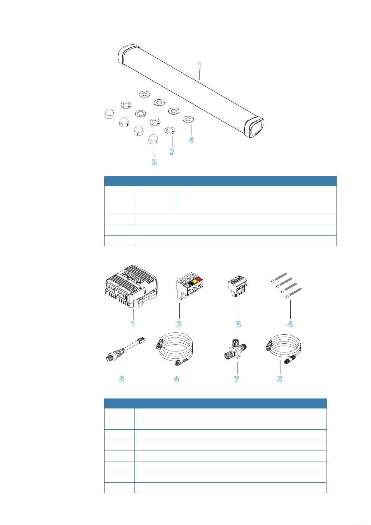
Antenna
2
No. Description
1
2
3
4
Radar antenna 3 ft (3.70 ft Antenna 1127 mm (44.37”))
Dome nuts, M8, 316 s/s
Spring washer, M8, 316 s/s
Flat washer, M8 x16x1.2, 316 s/s
1
4
3
4 ft (4.70 ft Antenna 1431 mm (56.34”))
6 ft (6.69 ft Antenna 2038 mm (80.24”))
RI-12 Radar interface module
1 2 3 4
5 6 7 8
No. Description
1
2
3
4
5
6
7
8
RI-12 Radar interface module
Connector for the pedestal interconnection cable
Connector for Aux In (NMEA 0183, remote power and park brake)
Mounting hard ware
Ethernet adapter. RJ45 male to 5 pin female 150 mm (5.9”)
Ethernet cable 1.8 m (6 ft)
Micro-C T Joiner
Micro-C drop cable 1.8 m (6 ft)
10 |
Check the parts |Halo pulse compression radar installation manual
Page 11
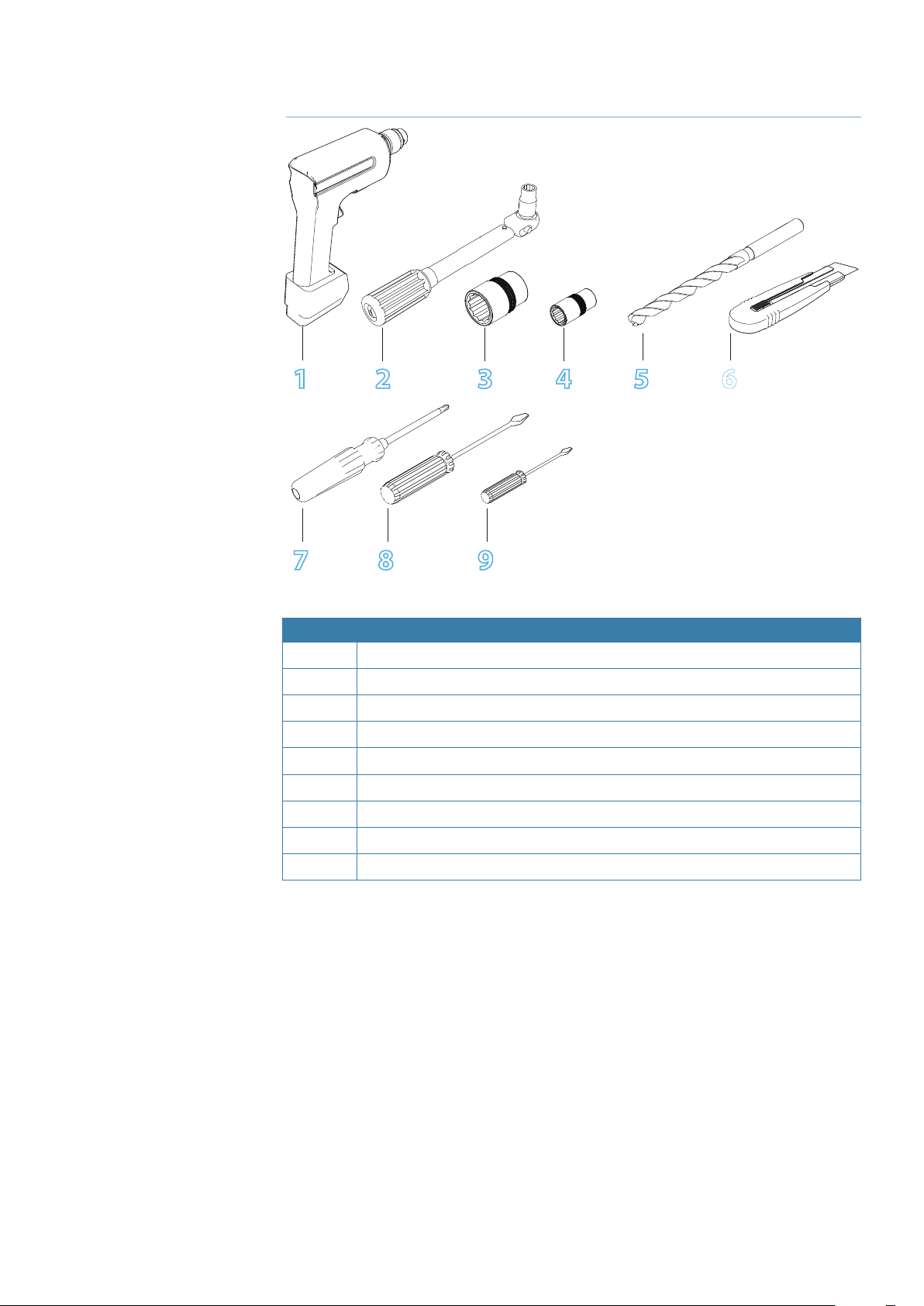
2
Tools required
1
2 3 4 5 6
7 8 9
No. Description
1
2
3
4
5
6
7
8
9
Drill
Torque wrench
19 mm socket
13 mm socket
Drill bit 12.5 mm (1/2")
Sharp Knife
Screw driver (pozidrive)
Screw driver (at blade)
Screw driver (at blade, small)
Tools required | Halo pulse compression radar installation manual
| 11
Page 12

!
!
3
Installation Guidelines
Warning: A radar unit should only be installed by a qualied marine technician, as
improper installation poses risks to the installer, the public, and to the safety of the vessel.
Warning: Before commencing any installation or maintenance on the Halo radar make
sure the safety switch on the rear of the pedestal is set to OFF
There is a transmit interlock that prevents radar transmissions if the scanner is not rotating.
However, a high voltage remains for a period of time after the system is turned o. If you are
not familiar with this type of electronics, consult with a trained service or installation technician
before attempting to service any part of the equipment.
Installation includes:
• mechanical mounting
• electrical wiring
• conguring the display or network system to work with the radar
• adjusting the radar for proper performance
The radar’s ability to detect targets depends greatly on the position of its scanner. The ideal
location for the scanner is high above the vessel’s keel line where there are no obstacles.
A higher installation position increases the radar ranging distance, but it also increases the
minimum range around the vessel where targets cannot be detected and increases seaclutter
pick up
When you’re deciding on the location, please consider:
• The length of the 20 m (66 ft) interconnection cable supplied with the radar is usually sucient.
A longer 30 m (98 ft) cable is available. 30 m (98 ft) is the longest the cable that can be used.
• If the roof of the wheelhouse is the highest existing location, consider installing a radar mast or
tower on which you can mount the radar. You may also need to construct a working platform
for your own safety during installation and servicing work.
• If you locate the scanner on the mast, position it on the forward side so that there is a clear view
to the front of the vessel.
• It is preferable to install the scanner parallel to the line of the keel.
DO NOT DO THIS!
• DO NOT install the scanner too high up, where its weight will alter the stability of the vessel and
cause degrade the radar picture over short ranges.
• DO NOT install the scanner close to lamps or exhaust outlets. The heat emissions may cause the
equipment to break down. Soot and smoke will degrade the performance of the radar.
• DO NOT install the scanner close to the antennas of other equipment such as direction nders,
VHF antennas, GPS equipment etc, as it may cause interference.
• DO NOT install the scanner where a large obstruction (such as an exhaust stack) is at the same
level as the beam. The obstruction is likely to generate false echoes and/or shadow zones. If
no other alternative location use the sector blanking feature in the radar software. (see “” on
page 33)
• DO NOT install the scanner where it will be subjected to strong vibrations because the
vibrations could degrade the performance of the radar.
• DO NOT install an open array close to halyards or ags because the wind could wrap these
around the antenna and jam it.
12 |
Installation Guidelines |Halo pulse compression radar installation manual
Page 13
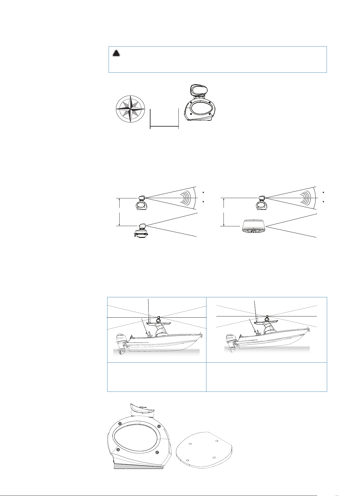
Compass safe distance
!
STD 1.0 m (3.3 ft)
Steer 0.5 m(1.6 ft)
Compass
N
EW
S
Warning: Do not install the scanner inside of the recommended compass safe distances
of any navigation instruments such as the magnetic compass and the chronometer. The
compass safe distances are as follows:
Minimum distance to install near the ships compass is 1.0m (3.3 ft).
Multi-radar installations
Vertical Separation
Pulse Compression Radar
2 m (6 ft)
Pulse Radar
TX
STBY
12.5
Pulse Compression Radar
12.5
3 m (9.8 ft)
3G / 4G Radar
TX
12.5
12.5
STBY
Do not install the Halo® pulse compression radar on the same beam plane as a conventional
pulse radar. A pulse radar must be set to STBY or OFF any time the Halo® radar is being operated.
¼ Note: Possible interference could be reduced by using the sector blanking feature (see “” on
page 33)
Power boat installations
If possible ensure that the location site
provides the scanner with a clear view all
round the vessel.
Installations on power boats that have a steep
planing angle, it is recommended to tilt the
scanner angle down at the front. (Beam angle is
12.5° either side of center).
¼ Note: Optional 4 degree wedge available from third party suppliers such as SeaView RW4-7
Installation Guidelines | Halo pulse compression radar installation manual
| 13
Page 14
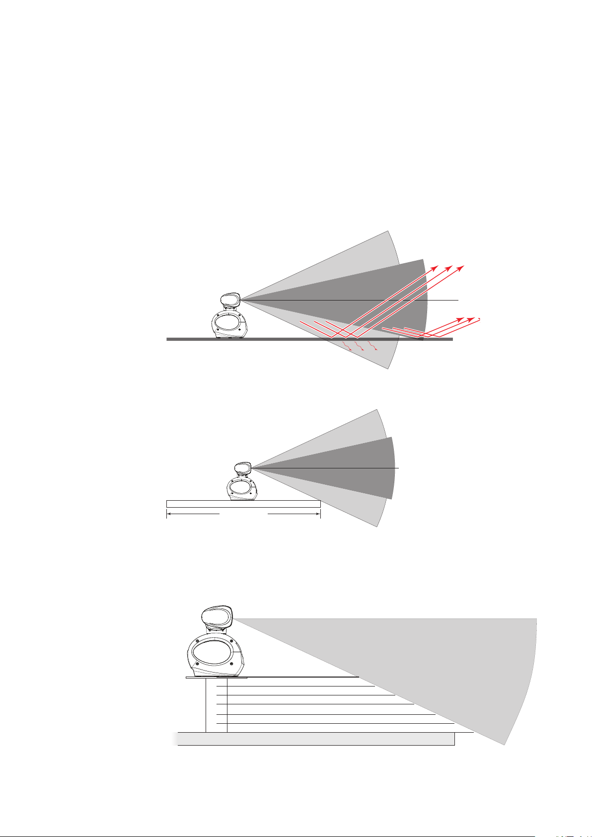
Considerations for direct roof mounting
Elevation of pedestal
When deciding a suitable mounting location for the Halo® Pulse Compression Radar be aware
that the vertical radar beam extends to 25° either side of horizontal. With 50% of the power
projecting in a beam 12.5° o horizontal. If the radar beams cannot clear the roof line, this will
decrease performance of the radar. Depending on the size of the hard top of the vessel, it is
recommended to elevate the antenna to allow the radar beams to clear the roof line. Below are
guide lines on heights above the hard top.
The below illustrates an installation with the Halo® Pulse Compression Radar mounted directly
on to a large hard top. This installation could suer decreased performance as the radar energy
is either reected or absorbed by the hard top.
¼ Note: Where the mounting surface is constructed of any form of metal you must elevate the
dome so that the beam has complete clearance, else performance will be severely impaired.
25°
25% of power
50% power
12.5°
12.5°
25°
For best performance, the radar should be positioned to allow the beams to clear the
superstructure of the boat.
25% of power
50% of power
25% of power
1.8 m (6ft)
Hard top width
Below is a guide to determine the antenna height in relation to a vessels hard top overall width.
Every Increase of 200 mm (7.9”) of hard top total width over 1.8m wide: Increase the height of
the antenna by 46 mm (1.8”)
14 |
Optimum performance
1.8 m (6 ft)
2.0 m (6.5 ft)
2.2 m (7.2 ft)
25°
2.4 m (7.8 ft)
2.6 m (8.5 ft)
2.8 m (9.1 ft)
3.0 m (9.8 ft)
46 mm
92 mm
138 mm
184 mm
230 mm
276 mm
(1.81")
(3.62")
(5.43")
(7.24")
(9.06")
(9.69")
Direct hard top mount
Total hard top width
There are many radar mounting options available from third party vendors such as Seaview,
Scanstrut and Edson. (see “Third party mounting options” on page 43)
Installation Guidelines |Halo pulse compression radar installation manual
Page 15

4
Hardware mounting
Install the RI-12 radar Interface module
Install the RI-12 in a dry location away from spray, rain, drips and condensation or excessive
heat. The mounting position should be easily accessible.
Always mount the RI-12 vertically, with the cable entry points facing downwards. This is to assist
in cooling and to assist stopping any possible water ingress though the cable grommets.
The RI-12 must be located where it can be easily connected to the ship’s ground, the pedestal
interconnection cable, the power cable and the NMEA 2000 network. Check that these cables
and the ship’s ground can easily reach the radar processor BEFORE you drill.
Use fasteners suited to the mounting surface material. If the material is too thin for self tappers,
reinforce it, or mount the RI-12 with machine screws nuts and washers. Use only 304 or 316
stainless steel fasteners. Mark the screw locations using RI-12 box as a template, and drill pilot
holes.
Hardware mounting | Halo pulse compression radar installation manual
| 15
Page 16

4 x M12 x 50 mm
For steel boats use the supplied
isolating washers
Isolating washer
Steel
Isolating washer
Install the pedestal
The eight hex head bolts supplied are suitable for surfaces up to 25 mm (1”) in thickness.
Use the 4 x M12 x 35 mm for a surface thickness from 5 mm (0.2”) up to 13 mm (1/2")
Use the 4 x M12 x 50 mm for surface thickness from 13 mm (1/2”) up to 25 mm (1”)
If using longer bolts make sure they are of marine grade stainless steel and allow for minimum
of 12 mm (0.3”) and maximum of 20 mm (0.7”) of thread contact.
20 mm (0.7")
5.0 mm (0.2") min
25.4 mm (1.0") max
Surface thickness from 5 mm (0.2”) up to 13 mm (1/2") Use Bolt
4 x M12 x 35 mm
Surface thickness from 13 mm (1/2”) up to 25 mm (1”) Use Bolt
1. Run the interconnection cable between the pedestal and the location of the RI-12 Interface
module. The 14 pin connector end of the interconnection cable connects to the pedestal.
¼ Note: Protect the connectors especially the RJ45 connector when pulling cable through the
boat and avoid putting strain on to the connectors
¼ Note: The interconnection cable is 9 mm in diameter. A 14 mm hole will be required in order
for the RJ45 connector end to pass through to the RI-12 or 24 mm for the 14 pin connector to
pass through to the pedestal..
2. Stick down the mounting template in the desired installation location, observing correct
orientation. (Minor deviation can be compensated for in the radar software).
16 |
Hardware mounting |Halo pulse compression radar installation manual
Page 17

3. Drill pilot holes, Then use a 12.5 mm (1/2”) drill bit to drill the four holes where shown on the
!
mounting template.
4. Remove the mounting template .
5. Lift the pedestal into position using the supplied lifting strap.
Warning: Do not lift the pedestal with the antenna attached
Hardware mounting | Halo pulse compression radar installation manual
| 17
Page 18

Surface mount: Rear cable connection
1. Position the scanner carefully over the bolt holes so that they are aligned.
2. Place a at washer and spring washer onto each bolt, as shown.
3. Insert bolts into the drilled holes and locate into the pedestals threaded mounting holes and
tighten securely.
¼ Note: The torque settings for the mounting bolts are 30 N.m – 40 N.m (22.1 ft·lbf – 39.5 ft·lbf).
18 |
4. Connect the 14 pin end of the interconnection cable. Take care to align the connector correctly
to avoid bending the pins. Secure the locking collar by rotating clockwise until it clicks.
Hardware mounting |Halo pulse compression radar installation manual
Page 19

Pole or tower mount: Discreet cable connection
The interconnection cable can be optionally connected discreetly underneath the pedestal by
moving the 14 pin connector at the rear of the pedestal to a bracket underneath the pedestal.
1. Remove the retaining nut and pull back the connector and y lead.
2. Fit the supplied blanking plug where the connector used to be.
¼ Note: The blanking plug is attached the bracket underneath the pedestal.
3. Re-route the internal y lead to the bracket and secure with the nut.
4. Connect the interconnection cable. Take care to align the connector correctly to avoid bending
the pins. Secure the locking collar by rotating clockwise until it clicks.
5. Lower the pedestal carefully over the bolt holes so that they are aligned.
6. Place a at washer and spring washer onto each bolt, as shown.
7. Insert bolts into the drilled holes and locate into the pedestals threaded mounting holes and
tighten securely.
Hardware mounting | Halo pulse compression radar installation manual
| 19
Page 20

Fitting the antenna to the pedestal
!
1. Remove the protective cap from the pedestal and the protective label on the antenna that
protects the wave guide.
Warning: Do not operate the radar without the antenna connected.
¼ Note: The protection label and waveguide cover is in place to prevent contaminants from
entering the waveguide. These covers MUST BE REMOVED IMMEDIATELY PRIOR TO INSTALLING THE ANTENNA TO THE PEDESTAL.
¼ Note: An antenna Sealing Ring is located under this label in the antenna waveguide chamber.
Ensure the Sealing Ring remains in place prior to installing the antenna to the pedestal.
3. Carefully lower the antenna on to the pedestal. The antenna can only t one way
20 |
x4
4. Place a at washer then a split washer followed by a dome nut on to each of the four antenna
studs. Tighten the dome nuts using socket and torque wrench to 15 N.m (11 ft·lbf)
¼ Note: A socket wrench is recommended to minimise risk of chipping the powder coated
surface of the pedestal
Hardware mounting |Halo pulse compression radar installation manual
Page 21

!
5
Wiring
Warning: SAFETY SWITCH. The pedestal unit has a safety switch, which removes power
from the radar and disables the antenna rotating during maintenance and service. Make sure
switch is set to o before commencing installation and back to ON after completion
All wiring connections are made inside the RI-12 interface box. It is necessary to remove the lid
to gain access to the connections
1. Remove the lid by unscrewing the six retaining screws
2. Remove the grommet retaining clip
3. Remove the rubber grommets
4. Pass the cables through the rubber grommets and into the RI-12. Use a sharp knife to cut a slit
the grommet.
Wiring | Halo pulse compression radar installation manual
| 21
Page 22

RI-12 connections
12 3
4 5
6 7
No. Name Description
1
2
3
4
5
6
7
8
9
10 NETWORK/MFD RJ45: Connects the radar to the navigation Ethernet
8 9 10
FUSE 25 Amp blade fuse
Power control: REMOTE Remote power control activation jumper. Move to
REMOTE position so radar power state is controlled
by a multifunction display or switch (see “Remote
power control” on page 27)
Power control: AUTO Radar will turn on when power is applied to the
main power connector. Remote power wire on AUX
IN port is ignored
SCANNER POWER Large green connector: Provides 36 V DC up to the
pedestal and power for the park brake. Connect the
four wires of the interconnection cable matching
the color coded sticker on the connector
NMEA 2000 Micro-C: NMEA 2000 network connection
SCREEN Alternative chassis ground connection (see
“Grounding requirements” on page 26)
- SUPPLY+ 12 or 24 V DC input
AUX IN Small connector: NMEA 0183 data input, remote
power on and DC input for the antenna park brake
SCANNER RJ45: Ethernet data from the pedestal. Connect the
RJ45 connector of the interconnection cable
network
22 |
Wiring |Halo pulse compression radar installation manual
Page 23

LED Indicator lights
LED Color Indication
Power Green steady Power is applied and the radar is turned on (by either
remote power on or power control jumper set to Auto).
Comms Green fast ashing NMEA 2000 trac present
Green slow ashing RI-12 with pedestal communication active
O No NMEA 2000 data and no communication with the
pedestal
Status Green steady Radar is transmitting
Orange Radar is in standby
Red Low input voltage < 10 V DC (RI-12 has stopped sending
power to the pedestal
Red ashing Power supply fault
Ethernet Green fast ashing Successful communications with an MFD
Green steady Physical connection to an Ethernet device exists but
there is no communication with any MFD
O No connection to any other active Ethernet device
Pedestal Interconnection cable
The interconnection cable connects the radar pedestal to the RI-12 Interface module. The cable
connects to the pedestal using a 14 pin connector. The pedestal 14 pin connector can be set
to either rear exit or discrete exit underneath the pedestal. (see “Pole or tower mount: Discreet
cable connection” on page 19)
¼ Note: Protect the connectors especially the RJ45 connector when pulling cable through the
boat and avoid putting strain on to the connectors.
The interconnection cable is 9 mm in diameter. A 14 mm hole will be required in order for the
RJ45 (Interface module end) to pass through bulkheads or 24 mm hole for the 14 pin connector
(pedestal end) to pass though.
Run the interconnection cable between the pedestal and the location of the RI-12 Interface
module.
Wiring | Halo pulse compression radar installation manual
| 23
Page 24

Cable connector
P1P8
Scanner connector
Diameter = 23 mm
RJ45 Connector pinout
Required to complete
Pin-
Wire color
out
1 Black Pedestal power DC (-)
2 Red Pedestal power DC (+)
3 Yellow Park angle retention
4 Drain Tinned wire
5 N/A N/A
6 Blue RJ45 Pin 4
7 White / Blue RJ45 Pin 5
8 White / Brown RJ45 Pin 7
9 Brown RJ45 Pin 8
10 White / Green RJ45 Pin 3
11 N/A N/A
12 White / Orange RJ45 Pin 1
13 Green RJ45 Pin 6
14 Orange RJ45 Pin 2
Pin Color
1 White/Orange
2 Orange
3 White/Green
4 Blue
5 White/Blue
6 Green
7 White/Brown
8 Brown
24 |
RJ45 Connector RJ45 Crimping tool
Connect the power cable
Power for the radar is connected to the RI-12 Interface module. The radar requires either a 12
or 24 V DC supply capable of delivering 15A for 12V system and 8A for 24V system continuous.
The RI-12 is protected against reverse polarity, over and under voltage. The RI-12 must be
connected to a dedicated fuse/circuit breaker. The fuse/circuit breaker should be labeled
accordingly.
Voltage Cable length
2 m (6.6 ft) 5 m (16.4 ft) 10 m (32 ft) 20 m (66 ft)
12 V DC 2.1 mm (12-AWG) 3.3 mm (8-AWG) 4.1 mm (6-AWG) N/A
24 V DC 1.3 mm (14-AWG) 2.1 mm (12-AWG) 3.3 mm (8-AWG) 4.1 mm (6-AWG)
¼ Note: Above values in mm=diameter of the cable conductor
¼ Note: The RI-12 has an optional remote power control mode that can enable a compatible
multifunction display or ignition switch to control the power state of the radar (see “Remote
power control” on page 27)
Wiring |Halo pulse compression radar installation manual
Page 25

Connecting power
1. Strip away approximately 10 mm (0.4” ) of the insulation at the end of each core of the power
cable
2. Unscrew the retention screw from the positive input connector (identied by the + sign) on the
radar processor
3. Insert the bare end of the positive wire into the positive power cable input connector to make
a connection
4. Tighten the holding screw to hold the positive wire in place. Gently pull on the positive wire to
ensure that it is secured
5. Repeat this process to connect the negative wire to the negative power cable input connector
(identied by the – sign)
_
+
12 or 24 V DC
Wiring | Halo pulse compression radar installation manual
| 25
Page 26

Grounding requirements
The RI-12 has a chassis ground terminal on the underside of the case. The chassis ground is DC
isolated from power (–ve) to eliminate the risk of galvanic corrosion.
It is recommended that the RI-12 ground is connected to the vessels bonded ground or a non
bonded RF ground at the closest possible location, using 12 AWG wire (or thicker):
26 |
Wiring |Halo pulse compression radar installation manual
Page 27

Remote power control
Remote power control is a feature that allows the power state of the radar to be controlled
either from a switch or when a compatible multifunction display is powered on or o.
¼ Note: The power control jumper must be moved from AUTO to REMOTE for the radar to use
the remote power on function.
¼ Note: +V DC (5 V DC - 32 V DC) from either a multifunction display set as power control mas-
ter or a switch can be applied to the REMOTE port of the AUX IN connector for the remote
power on to function.
Connect the yellow wire to external wake up of a compatible multifunction display to the
remote input. The radar will turn on when the display is turned on. The display must be set to
‘Master’ under Power Control. (Please refer to the displays user manual)
¼ Note: If the radar is turned o via remote power control while transmitting, The radar will auto
park the antenna before shutting down.
¼ Note: There must be a common batt -ve for all devices on power control bus.
No. Description
1
2
Halo® RI-12 Interface module
NSO evo2 or other multifunction display (one or more multifunction display needs
to be set to power control master)
3
4
5
Other Simrad device with remote power control
Power control bus
DC Power
1
2
POWER
TRANSDUCER 1
TRANSDUCER 2
SPEED
33
4
_
+
5
TEMPERATURE 1 TEMPERATURE 2
Wiring | Halo pulse compression radar installation manual
| 27
Page 28

Network
An Ethernet network is used to distribute the radar data to compatible multi-function displays.
The RI-12 is connected to the Ethernet network using a standard Simrad Ethernet cable and the
supplied adapter cable. The RI-12 can be connected either directly to any Simrad compatible
MFD or to a network switch such as an NEP-2 or SonarHub.
NETWORK /MFD
4
6
1
2
6
3
5
4
No. Description
1
2
3
4
5
6 Ethernet cables. Supplied with a 1.8 m (6 ft). The RI-12 can connect either directly
Halo® pulse compression radar pedestal and antenna
Multi-function displays
RI-12 interface module
RJ45 to 5 pin yellow Ethernet adapter (p/n 000-11246-001)
NEP-2 or device with a built in Ethernet switch
to a multifunction display or to other an Ethernet switch such as NEP2 or SonarHub
28 |
Wiring |Halo pulse compression radar installation manual
Page 29

NMEA 2000
The RI-12 can be connected to a Micro-C NMEA 2000 network to receive heading and position
information.
A heading sensor is required for the following functionality;
• MARPA : heading at 10 Hz or faster is required for the radar to calculate MARPA tracking. Heading
must also be connected to the display.
• Radar Chart overlay and North-up: Heading is required by the multi-function display
For heading sensors that output NMEA 0183 (see “NMEA 0183” on page 30)
For magnetic heading sensors, heading calibration should be performed before using MARPA
or Chart Overlay, and repeated annually, and after any major structural changes to the vessel.
1
43
5
_
12 V DC
5
+
6
T
7
No. Description
1
2
3
4
5
6 Network power 12 V DC
7 Micro-C backbone (NMEA 2000) with terminators
Halo® radar pedestal and antenna
RI-12 interface modules
NMEA 2000 compliant heading sensor
Compatible multifunction display
Micro-C drop cables
2
T
Wiring | Halo pulse compression radar installation manual
| 29
Page 30

NMEA 0183
The RI-12 has one NMEA 0183 (RS422) to accept heading and position information. The NMEA
0183 port is auto sensing and can accept 4800, 9600, 19200 or 38400 baud rates.
Sentences used HDG, HDT, HDM, GGA, GLL, RMC, VTG. Heading should be at a minium of 10
Hz update rate.
NMEA 0183 RX_A
NMEA 0183 RX_B
RI-12 heading source selection:
The RI-12 receives heading via the NMEA 2000 network and transmits this data to the radar,
where MARPA processing is performed.
For Simrad installations with more than one heading source the RI-12 will use the Simrad group
source. The source used by the Simrad group can be viewed or changed via the multifunction
display in the Settings>Network>Sources… menu.
¼ Note: If an NMEA 0183 heading source is connected the RI-12 will use this. It will ignore a
NMEA 2000 heading source.
Antenna park
The Halo® Pulse Compression Radar has the ability to stop rotating the antenna and hold it at
a predetermined angle in relation to the ships heading line. The park angle is set in the display
(see “Adjust open array park angle” on page 34). In conjunction with this setting there is a
park angle retention feature which is a very low current electromagnetic brake that will provide
resistance for the antenna to maintain a parked angle against wind and movement. The park
brake requires a continuous low current DC supply (10-32 V DC). This draws less than 100uA.
30 |
_
+
12 -24 V DC
Wiring |Halo pulse compression radar installation manual
Page 31

When all connections have been made and checked the safety switch on the rear of the
pedestal can be set to the ON position
Wiring | Halo pulse compression radar installation manual
| 31
Page 32

6
Setup and conguration
Setup and conguration of the Halo® radar has been simplied compared to traditional pulse
radars. There is no zero range adjustment (time delay), no warm up time, and no burn in
required.
Source
On the radar page, choose the radar to be setup using the source drop down. MENU>SOURCE
When setting up the Halo Pulse Compression radar choose either Halo-A or Halo-B
¼ Note: Following settings require the radar to be in Transmit mode. MENU>TRANSMIT
Entering radar setup on your display
Enter radar installation by pressing MENU > SETTINGS > RADAR > INSTALLATION.
There are three essential steps to setup the Halo® radar:
• Set antenna length
• Set antenna height
• Set bearing alignment
Select the antenna length
Select the correct length of antenna. Select Save to exit back to the radar installation page.
Adjust antenna height...
Set the radar scanner height. Use the slider control or the “+” or “-” buttons to set the value then
SAVE.
32 |
¼ Note: The antenna height is the height of the antenna above the water line. It is very impor-
tant to set the antenna height congured correctly as this will aect the sea clutter function.
Do not set the height to 0.
Setup and conguration |Halo pulse compression radar installation manual
Page 33

Adjust bearing alignment...
Adjust the heading marker. This is to align with the heading marker on the screen with the
center line of the vessel, this will compensate for any slight misalignment of the pedestal during
installation. Any inaccuracy will be evident when using MARPA or chart overlay.
Point the boat towards a stationary isolated object. Adjust the bearing alignment so the
heading line touches the end of the same object.
Use the slider control or the “+” or “-” buttons to set the value then SAVE
Setup and conguration | Halo pulse compression radar installation manual
| 33
Page 34

Sector blanking
0˚
On vessels where the radar is installed in close proximity to a mast or structure that could cause
unwanted reections or interference to appear on the radar image. Use the sector blanking
feature to stop the radar from transmitting in the direction up to four sectors.
¼ Note: Sectors are setup relative to the heading line of the radar. The bearing of the sector is
measured from the front of the vessel to the center line of the sector.
Adjust open array park angle
The park angle is the nal resting position of the antenna relative to the heading line of the
radar when the radar is set to standby. The antenna will stop rotating at the desired oset.
Optionally the antenna can be held in place against wind by connecting the antenna park wire
(see “Antenna park” on page 30).
¼ Note: When entering standby the antenna may rotate multiple times before coming to rest
Fwd.
90˚
Sidelobe suppression...
¼ Note: This control should only be adjusted by experienced radar users. Target loss in harbour
environments may occur if this control is not adjusted correctly.
Occasionally false target returns can occur adjacent to strong target returns such as large ships
or container ports.
This occurs because not all of the transmitted radar energy can be focused into a single beam
by the radar antenna, a small amount energy is transmitted in other directions.
This energy is referred to as sidelobe energy and occurs in all radar systems.
The returns caused by sidelobes tend to appear as arcs:
When the radar is mounted where there are metallic objects near the radar, sidelobe energy
increases because the beam focus is degraded. The increased sidelobe returns can be eliminated
using the Sidelobe Suppression control in the Radar installation menu.
By default this control is set to Auto, and normally should not need to be adjusted. However
if there is signicant metallic clutter around the radar, sidelobe suppression may need to be
increased. The control should be adjusted as follows:
34 |
Setup and conguration |Halo pulse compression radar installation manual
Page 35

1. Set radar range to between 1/2 nm to 1 nm and Sidelobe Suppression to Auto
2. Take the vessel to a location where sidelobe returns are likely to be seen. Typically this would be
near a large ship, container port, or metal bridge
3. Traverse the area until the strongest sidelobe returns are seen
4. Change Auto sidelobe suppression to OFF then select and adjust the sidelobe suppression
control until the sidelobe returns are just eliminated. You may need to monitor 5-10 radar
sweeps to be sure they have been eliminated
5. Traverse the area again and readjust if sidelobes returns still occur
6. Exit the installation menu
Radar Status
Provides information on the radar such as Software version, Serial number, and operating hours
Reset Radar to factory defaults
Reset to factory defaults function will only reset radar control settings, not installation settings.
Setup and conguration | Halo pulse compression radar installation manual
| 35
Page 36

Control pedestal accent lighting
!
The Halo™ Pulse Compression Radar pedestal has a blue accent light. The LED accent light has
four light levels controlled from the radar menu.
¼ Note: The accent light can only be adjusted when the radar is in standby
Halo™ Pulse Compression Radar’s blue 4 level static accent pedestal lighting may not be
approved for use in your boating location. Please check your local boating regulations before
turning the blue accent lights ON.
36 |
Setup and conguration |Halo pulse compression radar installation manual
Page 37

7
Specications
Description 25 W Halo® Pulse Compression Radar System
System consists of radar pedestal, antenna, Interconnection
cable and RI-12 Interface Module.
Type of emission FCC/IC/R&TTE Type Certication
FCC ID: RAYHALO
IC ID: 4697A-HALO
R&TTE: Emissions compliant to SM1541-4 (including -40
dB/dec future design objectives)
Environmental
Operating Temperature -25°C to +55°C (-13°F - 131°F)
Relative humidity IEC60945 Exposed product
Shock and Vibration IEC60945 Exposed product and 20G, 100,000 cycle
UV IEC60945 Exposed product
Waterproong IPX6
Relative wind velocity 70 knots for 3’, 4’, and 6’ antenna at 48 rpm with RI-12
Power
Power consumption 150 W (peak) at maximum wind velocity
40 W (average) at zero wind velocity
6.5 W (average) for Scanner + RI-12 in Standby mode
DC input R-12: 10.8 V DC to 31.2 V DC (12/24 volt systems)
Pedestal voltage input is 36 V DC nominal generated by RI-12
Power up time 16-25 seconds from POWER OFF to TRANSMIT
Physical
Height
Antenna swing circle diameter
Component weights Pedestal
Antenna
Instrumented range 3 ft model: 48 nm
Transmitter Solid state module with no long term transmitter power
Rotation Approx. 24 to 48 rpm (Min 20 rpm at Max 70 kts).
Beam width 3 ft: 2.4°+/-10% (-3 dB width) – 1.7 deg with Beam
Beam width Vertical 25° +/-20 % (-3 dB width)
Plane of polarization Horizontal Polarization
Sidelobe level 3 ft Below -23 dB max. (within ±10°)
448 mm (17.64”)
3 ft model: 1141 mm (3.5 ft)
4 ft model: 1431 mm (4.5 ft)
6 ft model: 2045 mm (6.5 ft)
18.75 Kg (41.3lb)
Antenna 3 ft
Antenna 4 ft
Antenna 6 ft
RI-12
10 m (33 ft) Cable
20 m (66 ft) Cable
30 m (100 ft) Cable
4 ft model: 64 nm
6 ft model: 72 nm
degradation
Software controlled in modes
sharpening mode ON
4 ft: 1.8°+/-10% (-3 dB width) – 1.3 deg with Beam
sharpening mode ON
6 ft 1.2°+/-10% (-3 dB width) - 0.8 deg with Beam
sharpening mode ON
Below –30 dB max. (outside ±10°)
4.1 Kg (9.0 lb)
4.9 Kg (10.8 lb)
6.5 Kg (14.3 lb)
1.6 Kg ( 3.5 lb)
1.1 Kg (2.4 lb)
2.3 Kg (5.0 lb)
3.4 Kg (7.5 lb)
Specications | Halo pulse compression radar installation manual
| 37
Page 38

Side lobe level 4 ft Below -23 dB max. (within ±10°)
Below –30 dB max. (outside ±10°)
Side lobe level 6 ft Below -23 dB max. (within ±10°)
Below –30 dB max. (outside ±10°)
Transmitter frequency Synthesized - Upper half of X-Band 9.410 - 9.495 GHz
Peak power output 25 W ± 10% under any transmit condition – up to 10%
duty cycle max
Pulse length/PRF and
Compression ratio
Pulse length: 0.04 usec
Chirp length:2-96 usec
Chirp Bandwidth: 2-32 MHz
Up to 1 pulse and 5 chirps in a burst with burst
repetition rate of 500-2000. Range and mode
dependent.
Eective Pulse Compression Ratio less than 150 in all
modes.
SART/RACON Triggering Yes – trigger distance: about 1nm max – weather, sea
state, and SART position dependent
Duplexer Circulator and isolator
Mixer MIC front-end
IF section Center frequency: 28.625 MHz
Bandwidth: 40 MHz max.* A/D; 16 bit 115 MSPS
*Narrower bandwidths dened by signal processing
Noise gure 5 dB (Average) at front-end input.
Compass safe distance STD. 1.0 m (3.3 ft) Steer 0.5 m 1.6 ft)
Other
Communications Ports Ethernet 10/100 Base-T for radar data and control
Micro-C male / NMEA2000 via RI-12
NMEA 2000 PGNS USED
127250 - Vessel Heading
127251 - Rate of Turn
129025 - Position, Rapid Update
129026 - COG & SOG, Rapid Update
129029 - GNSS Position Data
130818 - Proprietary
NMEA 0183 Input via RI-12 ..
Sentenses used by the radar application. HDG, HDT,
HDM, GGA, GLL, RMC, VTG.
Baud rate: Auto sense 4800, 9600, 19200 or 38400
Antenna park
Remote power on
Motor Brushless with solid state commutation with
electromagnetic braking for parking.
Inter-connecting cable Uses the same cable as the 3G/4G radars
Available in:
Ships with (
10 m (33 ft), 20 m (66 ft), 30 m (100 ft) lengths
20 m (66 ft) Max length 30 m (100 ft)
Options for cable to exit from rear of pedestal or pole
mount
38 |
Specications |Halo pulse compression radar installation manual
Page 39

82.7 mm (3.26")
86.2 mm (3.39")
8
Drawings
RI-12
92.5 mm (3.64")
196.5 mm (7.74")
213.0 mm (8.39")
195.0 mm (7.68")
Drawings | Halo pulse compression radar installation manual
| 39
Page 40

Pedestal and antennas
427 mm (16.81")
185 mm (7.28")
135 mm (5.31")
292 mm (11.50")
262 mm (10.31")
210 mm (8.27")
339 mm (13.35")
40 |
3.70 ft Antenna 1127 mm (44.37")
4.70 ft Antenna 1431 mm (56.34")
6.69 ft Antenna 2038 mm (80.24")
6 ft
4 ft
3 ft
Drawings |Halo pulse compression radar installation manual
170 mm (6.69")
324 mm (12.76")
Page 41

Antenna maximum rotation
6 ft
4 ft
2045 mm (80.51")
1431 mm (56.77")
1141 mm (44.92")
3 ft
Drawings | Halo pulse compression radar installation manual
| 41
Page 42

Spare Parts
Part Number Description
9
000-11463-001 Halo pedestal
000-11464-001 3 ft (1127 mm) antenna
000-11465-001 4 ft (1431 mm) antenna
000-11466-001 6 ft (2038 mm) antenna
000-11467-001 RI-12 Radar interface module
AA010211 Broadband scanner interconnection cable
10 m (33 ft)
AA010212 Broadband scanner interconnection cable
20 m (65.6 ft)
AA010213 Broadband scanner interconnection cable
30 m (98.5 ft)
000-11246-001 Adapter cable: yellow Ethernet female to RJ45
male. 150 mm (5.9”)
000-00127-28 Ethernet cable 0.6 m (2 ft)
000-0127-51 Ethernet cable 1.8 m (6 ft)
000-0127-29 Ethernet cable 4.5 m (15 ft)
000-0127-30 Ethernet cable 7.7 m (25 ft)
000-0127-37 Ethernet cable 15.2 m (50 ft)
24005936 AT10 NMEA0183 / NMEA 2000 converter (SimNet connector)
24006694 AT10HD NMEA0183 heading to/ NMEA 2000 converter.
(SimNet connector).
42 |
Spare Parts |Halo pulse compression radar installation manual
Page 43

Third party mounting options
Seaview (www.seaviewglobal.com)
Image Seaview part no. Description
PMF-57-M1 127 mm (5.7”) tall forward
leaning mount
PMA-57-M1 127 mm (5.7”) tall aft leaning
mount
ADA-R1 Top plate
ADA-HALO-3 Adapter plate. Used in
conjunction with ADA-R1
and a mounting tower
RW4-7 4° Angled wedge adapter
ADA-HALO-2 Adapter for replacing 3G/4G,
Raymarine and Garmin radars
with Halo
PMA-DM2-M2 Dual mount. (Not for 6 ft
Halo)
Spare Parts | Halo pulse compression radar installation manual
| 43
Page 44

Scanstrut (www.scanstrut.com)
Image Scanstrut Part No. Description
APT6003 150 mm (6”) Aluminium
PowerTower® for Halo (3 ft,
4 ft, 6ft)
DPT-40-SO3 Dual PowerTower® for 40 cm
satcom plus Halo 3 ft or 4 ft
DPT-60-SO3 Dual PowerTower® for 60 cm
satcom plus Halo 3 ft or 4 ft
44 |
Spare Parts |Halo pulse compression radar installation manual
Page 45

Page 46

*988-10676-001*
www.simrad-yachting.com
0560
 Loading...